EP0516952B1 - Wear-resistant roller to be used in roller crushers, in particular high-pressure roller crushers - Google Patents
Wear-resistant roller to be used in roller crushers, in particular high-pressure roller crushers Download PDFInfo
- Publication number
- EP0516952B1 EP0516952B1 EP92106594A EP92106594A EP0516952B1 EP 0516952 B1 EP0516952 B1 EP 0516952B1 EP 92106594 A EP92106594 A EP 92106594A EP 92106594 A EP92106594 A EP 92106594A EP 0516952 B1 EP0516952 B1 EP 0516952B1
- Authority
- EP
- European Patent Office
- Prior art keywords
- roller
- wear
- roll
- pieces
- material pieces
- Prior art date
- Legal status (The legal status is an assumption and is not a legal conclusion. Google has not performed a legal analysis and makes no representation as to the accuracy of the status listed.)
- Expired - Lifetime
Links
Images
Classifications
-
- B—PERFORMING OPERATIONS; TRANSPORTING
- B02—CRUSHING, PULVERISING, OR DISINTEGRATING; PREPARATORY TREATMENT OF GRAIN FOR MILLING
- B02C—CRUSHING, PULVERISING, OR DISINTEGRATING IN GENERAL; MILLING GRAIN
- B02C4/00—Crushing or disintegrating by roller mills
- B02C4/28—Details
- B02C4/30—Shape or construction of rollers
- B02C4/305—Wear resistant rollers
Definitions
- the invention relates to a wear-resistant grinding roller for use in high-pressure roller presses for material bed comminution of granular material with a large number of material pieces embedded in the roller body in the region of the roller surface.
- EP-A-0 361 172 proposes armoring the rollers of a high-pressure roller press for comminuting granular material by hard-armored layers of a special alloy being successively welded onto the roller base body via corresponding buffer layers, viewed radially from the inside out the hardness of the welded-on armor layers should increase towards the outside.
- the roller shell is composed of individual segments. Radially oriented sheets of softer material are poured into each segment, and the roll shell surface formed in this way is initially smooth cylindrical.
- a corrugated roll surface profile should then result in the course of the roll circumferential direction, which should not improve the wear behavior, but rather the grind feed behavior of the grinding rolls formed in this way.
- the surface of the known grinding roller which is initially smooth on the outside and then gradually corrugated during the operation of the roller, is not able to produce an autogenous, i.e. H. ensure wear protection caused by the grist itself.
- a grinding roller for roller bowl mills is known, with a roller shell which has dovetail-shaped grooves distributed over the circumference, in which strip-shaped wear inserts are embedded are, whose outer contour can be set back in comparison to the contour of the rest of the roll shell, so that seen in the circumferential direction of the roll as a corrugated roll surface arises.
- Autogenous wear protection is not associated with this; on the contrary, it appears from this document that it is important in the case of roller bowl mills that the friction caused by the difference in speed between the grinding bowl and the grinding roller prevents the solidification of caked material.
- roller bowl mill namely in a roller bowl mill from Loesche GmbH for coal grinding, it is known to glue disc-shaped, oxide ceramic material pieces into recesses in the roller shell and to dimension them so that they do not protrude from the roller surface contour, but that their The upper edges are 3 mm behind the surface of the jacket.
- roller bowl mills namely that the friction caused by the difference in speed between the grinding bowl and the grinding roller is intended to prevent solidification of caked material.
- the invention has for its object to provide a grinding roller of the type set forth in the preamble of claim 1 in such a way that an extremely high resistance to wear can be achieved.
- This object is achieved according to the invention with the measures of the characterizing part of claim 1.
- Advantageous configurations are specified in the subclaims.
- the inclusion of pin-shaped pieces of material in the roller material whereby part of the pin-shaped pieces of material protrude in a hedgehog shape from the roller body achieved that in the operation of the roller press - that is to say when carrying out the material bed comminution - the spaces formed between the protruding pin-shaped material pieces are filled with the comminuted material and remain filled.
- the material in the nip is pressed into the spaces between the pin-shaped pieces of material protruding from the roller body, comminuted grain against grain there and compressed into agglomerates of very low porosity or very high density , It is these Gutagglomerate or Gutpreß stresses that then surely remain in the gaps even during the roller revolutions without binder and in this way form a permanent autogenous wear protection for the highly stressed roller surfaces.
- the extremely high pressure load of> 50 MPa pressure or pressing force> 2000 kN / m roll length that occurs during the material bed crushing in the roll gap of a high-pressure roll press and acts on the material to be ground does not only act in a radial direction on the two press rolls and thus on their bearing blocks, but it also acts as a result of the approximately isostatic pressing in the area of the narrowest roll gap in the roll circumferential direction.
- the good material which is pressed into the gap between the above pins in the nip of the high-pressure roller press, is comminuted there well (for example 30% ⁇ 90 ⁇ m) and is more dense to the very dense agglomerates or pressure scales Density is pressed, these Gutagglomerate then remain in the gaps and protect the hedgehog-shaped material pins against breakage (stress in the radial direction of the rollers) and shear (stress in the circumferential direction of the rollers), which was not predictable.
- the high roller press pressure is therefore used simultaneously for two purposes, namely for the high-pressure material bed shredding itself and for the protection of the projecting pin-shaped material pieces, which in turn are the prerequisite for ensuring the ideal autogenous wear protection for the rotating roller surfaces.
- the hard pin-shaped pieces of material can be embedded in the correspondingly shaped recesses in the roller body by gluing or pressing. In this way, a firm connection is made between the brittle, hard, pin-shaped material pieces and the roller body, which is retained due to the elastic nature of the roller body under external loads. According to the invention, however, it is also possible to achieve a firm connection between the pin-shaped material pieces and the roller body by another method, such as, for example, by shrinking, soldering, welding or screwing.
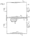
- Fig. 1 shows the high-pressure roller press for crushing granular material, which is fed from above via a feed hopper, not shown in the drawing, the roller gap (15) between the two grinding rollers (10, 11).
- a large number of wear-resistant material pieces designed in the form of pins (13) are embedded in the lateral surface (14) of the driven counter-rotating grinding rollers (10, 11).
- any combination of pieces of material in the form of a pin can also be used with variable dimensions and with variable distances from one another in the outer surface of the grinding roller and in the end face of the grinding roller and firmly connected to them by gluing, pressing, soldering, welding, shrinking, etc.
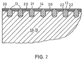
- pin-shaped material pieces (13) in which only a part is embedded in the lateral surface of the roller body (10, 11) and the remaining part is hedgehog-shaped from the roller body (10, 11) protrudes so that this protruding part is frustoconical at its upper end.
- the truncated cone lateral surface (22) advantageously prevents lateral forces which can act on the protruding parts during operation of the grinding roller lead to undesirable torques and thus to the protruding parts of the pin-shaped material pieces breaking off.
- the protruding part can also be hemispherical at its upper end.
- the spaces between the protruding pin-shaped material pieces (13) can be up to the upper edge (21) of the pin-shaped material pieces (13) with another material (20) - this can be, for example, a ceramic mass or, for example, one with ceramic materials Trade plastic - be filled so that a closed roll surface (14) is obtained.
- the gaps can, however, advantageously also initially remain free, so that they fill up granular material with material only when the roller machine is in operation and when the material bed comminution is carried out, and so form a closed roller surface (14).
Abstract
Description
Die Erfindung betrifft eine verschleißfeste Mahlwalze für die Verwendung in Hochdruck-Walzenpressen zur Gutbettzerkleinerung körnigen Gutes mit einer Vielzahl von im Bereich der Walzenoberfläche in den Walzenkörper eingelagerten Werkstoffstücken.The invention relates to a wear-resistant grinding roller for use in high-pressure roller presses for material bed comminution of granular material with a large number of material pieces embedded in the roller body in the region of the roller surface.
Bei Walzenbrechern und Walzenmühlen wird körniges sprödes Mahlgut in den Walzenspalt, durch den die beiden drehbar gelagerten, gegenläufig rotierbaren Mahlwalzen voneinander getrennt sind, eingezogen und dort einer Druckzerkleinerung unterworfen.In the case of roller crushers and roller mills, granular, brittle regrind is drawn into the roller gap, through which the two rotatably mounted, counter-rotating grinding rollers are separated from one another and subjected to pressure comminution there.
Bekannt ist auch die sogenannte Gutbettzerkleinerung im Walzenspalt einer Hochdruck-Walzenpresse, bei der die einzelnen Partikel des eingezogenen Mahlgutes in einem Gutbett, d. h. in einer zwischen den beiden Walzenoberflächen zusammengedrückten Materialschüttung bei Anwendung eines extrem hohen Druckes gegenseitig zerkleinert werden (EP-B-0 084 383). Dabei sind die Walzenoberflächen einer außerordentlich hohen Beanspruchung ausgesetzt, woraus u. a. ein hoher Verschleiß der Walzenoberflächen resultiert. Es ist bekannt, durch besondere Beschichtungen der dem Verschleiß ausgesetzten Walzenoberflächen diesem Verschleiß entgegenzuwirken. So wird in der EP-A-0 361 172 vorgeschlagen, die Walzen einer Hochdruck-Walzenpresse zur Gutbettzerkleinerung körnigen Gutes dadurch zu panzern, indem auf den Walzengrundkörper nacheinander über entsprechende Pufferschichten harte Panzerschichten einer besonderen Legierung aufgeschweißt werden, wobei radial von innen nach außen gesehen die Harte der aufgeschweißten Panzerschichten nach außen hin zunehmen soll.Also known is the so-called material bed comminution in the nip of a high-pressure roller press, in which the individual particles of the ground material drawn in are mutually comminuted in a material bed, that is to say in a bed of material compressed between the two roller surfaces when an extremely high pressure is applied (EP-B-0 084 383). The roller surfaces are exposed to extremely high stress, which results in high wear on the roller surfaces. It is known to counteract this wear by special coatings on the roller surfaces exposed to wear. For example, EP-A-0 361 172 proposes armoring the rollers of a high-pressure roller press for comminuting granular material by hard-armored layers of a special alloy being successively welded onto the roller base body via corresponding buffer layers, viewed radially from the inside out the hardness of the welded-on armor layers should increase towards the outside.
Bei einer den Oberbegriff des Anspruchs 1 bildenden bekannten Mahlwalze für die Verwendung in Hochdruck-Walzenpressen zur Gutbettzerkleinerung körnigen Gutes (EP-A-0 396 897) ist der Walzenmantel aus einzelnen Segmenten zusammengesetzt. In jedes Segment sind radial ausgerichtete Bleche aus weicherem Material eingegossen, und die auf diese Weise ausgebildete Walzenmanteloberfläche ist zunächst glatt zylindrisch. Im Betrieb der Gutbettwalzenmühle soll sich dann im Laufe der Zeit in Walzenumfangsrichtung gesehen eine gewellte Walzenmanteloberflächenprofilierung ergeben, die nicht das Verschleißverhalten, sondern das Mahlgut-Einzugsverhalten der auf diese Weise ausgebildeten Mahlwalzen verbessern soll. Die zunächst außen glatte und während des Walzenbetriebes dann allmählich gewellte Wälzenmanteloberfläche der bekannten Mahlwalze ist nicht in der Lage, einen autogenen, d. h. einen durch festgehaltenes Mahlgut selbst bewirkten Verschleißschutz sicherzustellen.In a known grinding roller forming the preamble of claim 1 for use in high-pressure roller presses for comminuting granular material (EP-A-0 396 897), the roller shell is composed of individual segments. Radially oriented sheets of softer material are poured into each segment, and the roll shell surface formed in this way is initially smooth cylindrical. In operation of the material bed roller mill, a corrugated roll surface profile should then result in the course of the roll circumferential direction, which should not improve the wear behavior, but rather the grind feed behavior of the grinding rolls formed in this way. The surface of the known grinding roller, which is initially smooth on the outside and then gradually corrugated during the operation of the roller, is not able to produce an autogenous, i.e. H. ensure wear protection caused by the grist itself.
Ebenfalls zur Verbesserung des Mahlgut-Einzugsverhaltens ist es aus der EP-B-0 271 336 bekannt, in die Oberfläche einer Brecherwalze, die aus weniger verschleißfestem Material besteht, Längsnuten einzuarbeiten, die mit Abstand um den Walzenumfang verteilt angeordnet sind, und in diese Nuten Blöcke aus verschleißfesterem Material einzubringen. Beim Betrieb eines solchen Walzenbrechers soll dann aufgrund des schnelleren Verschleißes des weniger verschleißfesten Grundmateriales eine gewellte Walzenoberfläche entstehen, wiederum allein zu dem Zweck, den Einzug des Gutmaterials in den Walzenspalt und damit den Gutdurchsatz durch den Walzenbrecher zu erhöhen. Auch dieser Schrift sind keinerlei Maßnahmen zur Verschleißminderung von Walzenoberflächen, insbesondere von Walzen zur Durchführung der Gutbettzerkleinerung körnigen Gutes und/oder Hinweise auf einen autogenen Verschleißschutz der Walzenmanteloberfläche zu entnehmen.Also to improve the regrind feed behavior, it is known from EP-B-0 271 336 to incorporate longitudinal grooves, which are spaced around the circumference of the roller, into the surface of a crusher roller, which is made of less wear-resistant material, and into these grooves Insert blocks made of more wear-resistant material. When such a roller crusher is operated, a corrugated roller surface should then arise due to the faster wear of the less wear-resistant base material, again for the sole purpose of increasing the feed of the good material into the nip and thus the throughput of the material through the roller crusher. This document also does not contain any measures for reducing the wear of roller surfaces, in particular rollers for carrying out the comminution of granular material and / or indications of an autogenous wear protection of the roller shell surface.
Aus der DE-A-26 43 307 ist eine Mahlwalze für Walzenschüsselmühlen bekannt, mit einem Walzenmantel, der über den Umfang verteilt angeordnete schwalbenschwanzförmigen Nuten aufweist, in denen leistenförmige Verschleißeinsätze eingebettet sind, deren äußere Kontur im Vergleich zur Kontur des übrigen Walzenmantels zurückgesetzt sein kann, so daß in Walzenumfangsrichtung gesehen wie derum eine gewellte Walzenoberfläche entsteht. Ein autogener Verchleißschutz ist damit nicht verbunden; ganz im Gegenteil geht aus dieser Schrift hervor, daß es bei Walzenschüsselmühlen darauf ankommt, daß die durch die Differenzgeschwindigkeit zwischen Mahlschüssel und Mahlwalze entstehende Reibung das Festwalzen von anbackendem Gut vermieden wird.From DE-A-26 43 307 a grinding roller for roller bowl mills is known, with a roller shell which has dovetail-shaped grooves distributed over the circumference, in which strip-shaped wear inserts are embedded are, whose outer contour can be set back in comparison to the contour of the rest of the roll shell, so that seen in the circumferential direction of the roll as a corrugated roll surface arises. Autogenous wear protection is not associated with this; on the contrary, it appears from this document that it is important in the case of roller bowl mills that the friction caused by the difference in speed between the grinding bowl and the grinding roller prevents the solidification of caked material.
Ebenfalls bei einer Walzenschüsselmühle, und zwar bei einer Walzenschüsselmühle der Fa. Loesche GmbH zur Kohlemahlung ist es bekannt, in Ausnehmungen des Walzenmantels scheibenförmige, aus Oxyd-Keramik bestehende Werkstoffstücke einzukleben und so zu dimensionieren, daß sie von der Walzenoberflächenkontur nicht vorstehen, sondern daß ihre Oberkanten um 3 mm gegenüber der Manteloberfläche zurückliegen. Auch hierzu gilt das vorhin zu Walzenschüsselmühlen Gesagte, nämlich daß durch die infolge der Differenzgeschwindigkeit zwischen Mahlschüssel und Mahlwalze entstehende Reibung ein Festwalzen von anbackendem Gut gerade vermieden werden soll.Also in a roller bowl mill, namely in a roller bowl mill from Loesche GmbH for coal grinding, it is known to glue disc-shaped, oxide ceramic material pieces into recesses in the roller shell and to dimension them so that they do not protrude from the roller surface contour, but that their The upper edges are 3 mm behind the surface of the jacket. Here, too, what has been said about roller bowl mills applies, namely that the friction caused by the difference in speed between the grinding bowl and the grinding roller is intended to prevent solidification of caked material.
Schließlich ist aus der US-A-2,228,480 ein Walzenbrecher bekannt mit Walzen, auf deren Walzenmantel mittels Schraubenbolzen leistenförmige Werkstoffplatten befestigt sind, wobei zwischen benachbarten Werkstoffplatten eine Stufe ausgebildet sein kann. Ein autogener Verschleißschutz ist bei diesem bekannten Walzenbrecher nicht vorgesehen.Finally, from US-A-2,228,480 a roll crusher is known with rolls, on the roll shell of which strip-shaped material plates are fastened by means of screw bolts, it being possible for a step to be formed between adjacent material plates. Autogenous wear protection is not provided in this known roll crusher.
Der Erfindung liegt die Aufgabe zugrunde, eine Mahlwalze der im Oberbegriff des Anspruchs 1 vorgesetzten Art so auszubilden, daß ein extrem hoher Widerstand gegenüber Verschleiß erzielbar ist. Diese Aufgabe wird gemäß der Erfindung mit den Maßnahmen des Kennzeichnungsteils des Anspruchs 1 gelöst. Vorteilhafte Ausgestaltungen sind in den Unteransprüche angegeben.The invention has for its object to provide a grinding roller of the type set forth in the preamble of claim 1 in such a way that an extremely high resistance to wear can be achieved. This object is achieved according to the invention with the measures of the characterizing part of claim 1. Advantageous configurations are specified in the subclaims.
Bei der erfindungsgemäßen verschleißfesten Mahlwalze für die Verwendung in Hochdruck-Walzenpressen zur Gutbettzerkleinerung körnigen Gutes wird durch die Einlagerung von stiftförmig ausgebildeten Werkstoffstücken in das Walzenmaterial, wobei ein Teil der stiftförmigen Werkstoffstücke igelförmig aus dem Walzenkörper herausragt, erreicht, daß im Betrieb der Walzenpresse - also bei Durchführung der Gutbettzerkleinerung - die zwischen den überstehenden stiftförmigen Werkstoffstücken gebildeten Zwischenräume mit dem Zerkleinerungsgut gefüllt sind und gefüllt bleiben. Denn bei der Gutbettzerkleinerung spröder Materialien im Walzenspalt einer Hochdruck-Walzenpresse, beschrieben in der eingangs genannten EP-B-0 084 383, werden die Materialien im Spalt zwischen den Walzen mit einem außerordentlich hohen Druck von > 50 MPa, d. h. umgerechnet mit einer Preßkraft von mehr als 2000 kN/m Walzenlänge gepreßt, was teils zur Partikelzerstörung, teils zur Erzeugung von Anrissen im Partikelinneren führt und was bei diesem extrem hohen Druck zur Bildung von Agglomeraten bzw. Preßschülpen führt, die dann in einer zweiten Verfahrensstufe durch weitere mechanisehe Beanspruchung wieder zerstört bzw. aufgelöst werden müssen.In the wear-resistant grinding roller according to the invention for use in high-pressure roller presses for comminution of granular material, the inclusion of pin-shaped pieces of material in the roller material whereby part of the pin-shaped pieces of material protrude in a hedgehog shape from the roller body, achieved that in the operation of the roller press - that is to say when carrying out the material bed comminution - the spaces formed between the protruding pin-shaped material pieces are filled with the comminuted material and remain filled. This is because in the case of material bed comminution of brittle materials in the nip of a high-pressure roller press, described in the aforementioned EP-B-0 084 383, the materials in the nip between the rollers are subjected to an extraordinarily high pressure of> 50 MPa, ie converted with a pressing force of more than 2000 kN / m roller length pressed, which partly leads to particle destruction, partly to the creation of cracks inside the particles and which at this extremely high pressure leads to the formation of agglomerates or press scales, which are then destroyed again in a second process step by further mechanical stress or must be dissolved.
Bei den erfindungsgemäßen Walzen für eine Hochdruck-Walzenpresse zur Gutbettzerkleinerung körnigen Gutes wird also das Gut im Walzenspalt in die Zwischenräume zwischen den aus dem Walzenkörper igelförmig herausragenden stiftförmigen Werkstoffstücke hineingepreßt, dort Korn gegen Korn gutbettzerkleinert und zu Gutagglomeraten sehr geringer Porosität bzw. sehr hoher Dichte verpreßt, wobei es diese Gutagglomerate bzw. Gutpreßkörper sind, die dann mit Sicherheit auch während der Walzenumdrehungen ohne Bindemittel in den Zwischenräumen liegenbleiben und auf diese Weise einen bleibenden autogenen Verschieißschutz für die hochbeanspruchten Walzenoberflächen bilden.In the case of the rollers according to the invention for a high-pressure roller press for comminuting granular material, the material in the nip is pressed into the spaces between the pin-shaped pieces of material protruding from the roller body, comminuted grain against grain there and compressed into agglomerates of very low porosity or very high density , It is these Gutagglomerate or Gutpreßkörper that then surely remain in the gaps even during the roller revolutions without binder and in this way form a permanent autogenous wear protection for the highly stressed roller surfaces.
Die bei der Gutbettzerkleinerung im Walzenspalt einer Hochdruck-Walzenpresse auftretende und auf das Mahlgut einwirkende extrem hohe Druckbeanspruchung von > 50 MPa Druck bzw. Preßkraft > 2000 kN/m Walzenlänge wirkt nicht nur in radialer Richtung auf die beiden Pressenwalzen und damit auf deren Lagerböcke ein, sondern sie wirkt auch infolge des angenähert isostatischen Pressens im Bereich des engsten Walzenspaltes in Walzenumfangsrichtung. Der mit der Gutbettzerkleinerung vertraute Durchschnittsfachmann wäre auch bei Kenntnis des in der Beschreibungseinleitung geschilderten Standes der Technik nicht auf die Idee gekommen, die Oberfläche solcher Gutbetteerkleinerungs-Preessenwalzen mit nach außen vorstehenden stiftförmig ausgebildeten Werkstoffstücken zu versehen, in der Annahme, daß solche vergleichsweise weit vorspringenden Profile den extrem hohen Druckbelastungen, auch Punktbelastungen sowie auch Scherbelastungen nicht standhalten können und beim Betrieb solcher Gutbettzerkleinerungs-Walzenpressen zerstört werden wurden. Überraschenderweise hat sich aber gezeigt, daß das Gutmaterial, welches im Spalt der Hochdruck-Walzenpresse in die Zwischenräume zwischen den vorstehenden Stiften hineingepreßt wird, dort gutbettzerkleinert (z. B. 30 % < 90 µm) und zu den sehr dichten Gutagglomeraten bzw. Preßschülpen hoher Dichte verpreßt wird, wobei diese Gutagglomerate in den Zwischenräumen dann liegenbleiben und dabei die igelförmig hervorstehenden Werkstoffstifte gegen Bruch (Beanspruchung in radialer Richtung der Walzen) und Abscherung (Beanspruchung in Umfangsrichtung der Walzen) schützen, was nicht vorhersehbar war. Der hohe Walzenpreßdruck wird also gleichzeitig für zwei Ziele ausgenutzt, nämlich für die Hochdruck-Gutbettzerkleinerung selbst sowie für den Schutz der vorspringenden stiftförmigen Werkstoffstücke, welche wiederum die Voraussetzung sind zur Gewährleistung des idealen autogenen Verschleißschutzes für die rotierenden Walzenoberflächen.The extremely high pressure load of> 50 MPa pressure or pressing force> 2000 kN / m roll length that occurs during the material bed crushing in the roll gap of a high-pressure roll press and acts on the material to be ground does not only act in a radial direction on the two press rolls and thus on their bearing blocks, but it also acts as a result of the approximately isostatic pressing in the area of the narrowest roll gap in the roll circumferential direction. The average specialist familiar with material bed crushing would also be familiar with the in the introductory description of the prior art described did not come up with the idea of providing the surface of such good bed reduction press rolls with outwardly projecting pin-shaped material pieces, on the assumption that such comparatively widely protruding profiles do not withstand the extremely high pressure loads, also point loads and also shear loads can and were destroyed during the operation of such material bed crushing roller presses. Surprisingly, however, it has been shown that the good material, which is pressed into the gap between the above pins in the nip of the high-pressure roller press, is comminuted there well (for example 30% <90 μm) and is more dense to the very dense agglomerates or pressure scales Density is pressed, these Gutagglomerate then remain in the gaps and protect the hedgehog-shaped material pins against breakage (stress in the radial direction of the rollers) and shear (stress in the circumferential direction of the rollers), which was not predictable. The high roller press pressure is therefore used simultaneously for two purposes, namely for the high-pressure material bed shredding itself and for the protection of the projecting pin-shaped material pieces, which in turn are the prerequisite for ensuring the ideal autogenous wear protection for the rotating roller surfaces.
Die Einlagerung der harten stiftförmigen Werkstoffstücke in die entsprechend ausgebildeten Ausnehmungen des Walzenkörpers kann durch Kleben oder Einpressen erfolgen. Auf diese Weise wird zwischen den spröden harten stiftförmigen Werkstoffstücken und dem Walzenkörper eine feste Verbindung hergestellt, die aufgrund der elastischen Beschaffenheit des Walzenkörpers bei Belastungen von außen erhalten bleibt. Erfindungsgemäß ist es aber auch möglich, eine feste Verbindung zwischen den stiftförmigen Werkstoffstücken und dem Walzenkörper durch ein anderes Verfahren herbeizuführen wie beispielsweise durch Schrumpfen, Löten, Schweißen oder Schrauben.The hard pin-shaped pieces of material can be embedded in the correspondingly shaped recesses in the roller body by gluing or pressing. In this way, a firm connection is made between the brittle, hard, pin-shaped material pieces and the roller body, which is retained due to the elastic nature of the roller body under external loads. According to the invention, however, it is also possible to achieve a firm connection between the pin-shaped material pieces and the roller body by another method, such as, for example, by shrinking, soldering, welding or screwing.
Die Erfindung und deren weitere Merkmale und Vorteile werden anhand des in den Figuren schematisch dargestellten Ausführungsbeispieles näher erläutert.The invention and its further features and advantages are explained in more detail with reference to the exemplary embodiment shown schematically in the figures.
Es zeigt:
- Fig. 1:
- eine Draufsicht auf die beiden Walzen einer Hochdruck-Walzenpresse zur Gutbettzerkleinerung körnigen Gutes mit bei einer der beiden Walzen teilweise eingezeichneten eingelagerten stiftförmig ausgebildeten Werkstoffstücken, und
- Fig. 2:
- einen Teilschnitt einer Mahlwalze geschnitten in einer Ebene parallel zur Walzenachse.
- Fig. 1:
- a plan view of the two rollers of a high-pressure roller press for material bed comminution of granular material with embedded pin-shaped material pieces partially drawn in on one of the two rollers, and
- Fig. 2:
- a partial section of a grinding roller cut in a plane parallel to the roller axis.
Fig. 1 zeigt die Hochdruck-Walzenpresse zur Druckzerkleinerung körnigen Gutes, welches von oben über einen in der Zeichnung nicht dargestellten Gutaufgabeschacht dem Walzenspalt (15) zwischen den beiden Mahlwalzen (10, 11) zugeführt wird. In die Mantelfläche (14) der angetriebenen gegenläufig drehbaren Mahlwalzen (10, 11) sind eine Vielzahl von stiftförmig (13) ausgebildeten verschleißfesten Werkstoffstücken eingelagert.Fig. 1 shows the high-pressure roller press for crushing granular material, which is fed from above via a feed hopper, not shown in the drawing, the roller gap (15) between the two grinding rollers (10, 11). A large number of wear-resistant material pieces designed in the form of pins (13) are embedded in the lateral surface (14) of the driven counter-rotating grinding rollers (10, 11).
Die in Figur 1 dargestellte Anordnung von stiftförmig ausgebildeten Werkstoffstücken sowie die Abmessungen der einzelnen Werkstoffstücke und die Abstände der Werkstoffstücke voneinander stellen nur ein Beispiel für eine mögliche Ausführung der Einlagerung dar. Es können beispielsweise auch beliebige Kombinationen von stiftförmig ausgebildeten Werkstoffstücken mit variablen Abmessungen und mit variablen Abständen voneinander in die Mantelfläche der Mahlwalze und in die Stirnfläche der Mahlwalze eingelagert und mit diesen durch Kleben, Einpressen, Löten, Schweißen, Schrumpfen etc. fest verbunden werden.The arrangement of pieces of material in the form of a pin, as well as the dimensions of the individual pieces of material and the spacing of the pieces of material from one another, are only one example of a possible embodiment of the embedding. For example, any combination of pieces of material in the form of a pin can also be used with variable dimensions and with variable distances from one another in the outer surface of the grinding roller and in the end face of the grinding roller and firmly connected to them by gluing, pressing, soldering, welding, shrinking, etc.
Nach dem Ausführungsbeispiel der Fig. 2 ist es auch möglich, die stiftförmig ausgebildeten Werkstoffstücke (13), bei denen nur ein Teil in die Mantelfläche des Walzenkörpers (10, 11) eingelagert ist und der restliche Teil igelförmig aus dem Walzenkörper (10, 11) herausragt, so auszuführen dass dieser überstehende Teil an seinem oberen Ende kegelstumpfförmig ausgebildet ist.According to the embodiment of FIG. 2, it is also possible to use the pin-shaped material pieces (13), in which only a part is embedded in the lateral surface of the roller body (10, 11) and the remaining part is hedgehog-shaped from the roller body (10, 11) protrudes so that this protruding part is frustoconical at its upper end.
Die Kegelstumpf-Mantelfläche (22) verhindert vorteilhaft, daß seitliche Kräfte, die beim Betrieb der Mahlwalze an den herausragenden Teilen angreifen können, zu unerwünschten Drehmomenten und somit zu einem Abbrechen der herausragenden Teile der stiftförmig ausgebildeten Werkstoffstücke führen. Aus dem gleichen Grund kann erfindungsgemäß der überstehende Teil an seinem oberen Ende auch halbkugelförmig ausgebildet sein.The truncated cone lateral surface (22) advantageously prevents lateral forces which can act on the protruding parts during operation of the grinding roller lead to undesirable torques and thus to the protruding parts of the pin-shaped material pieces breaking off. For the same reason, according to the invention the protruding part can also be hemispherical at its upper end.
Die Zwischenräume zwischen den überstehenden stiftförmig ausgebildeten Werkstoffstücken (13) können bis zur Oberkante (21) der stiftförmig ausgebildeten Werkstoffstücke (13) mit einem weiteren Werkstoff (20) - es kann sich hierbei beispielsweise um eine keramische Masse oder beispielsweise um einen mit keramischen Materialien versetzten Kunststoff handeln - gefüllt werden, so daß eine geschlossene Walzenmanteloberfläche (14) erhalten wird.The spaces between the protruding pin-shaped material pieces (13) can be up to the upper edge (21) of the pin-shaped material pieces (13) with another material (20) - this can be, for example, a ceramic mass or, for example, one with ceramic materials Trade plastic - be filled so that a closed roll surface (14) is obtained.
Die Zwischenräume können mit Vorteil aber auch zunächst frei bleiben, so daß sie sich erst beim Betrieb der Walzenmaschine, bei Durchführung der Gutbettzerkleinerung körnigen Gutes mit Gutsmaterial auffüllen und so eine geschlossene Walzenmanteloberfläche (14) bilden.The gaps can, however, advantageously also initially remain free, so that they fill up granular material with material only when the roller machine is in operation and when the material bed comminution is carried out, and so form a closed roller surface (14).
Claims (3)
- A wear-resistant crushing roll or roller for use in high-pressure roll or roller crushers or presses for the interparticle crushing of granular material, the roll or roller being provided with a plurality of material pieces (13) embedded in the roll body (10, 11) in the region of the roll surface, characterised by the following features in combination :a) the embedded material pieces (13) are harder then the surrounding material of the roll or roller;b) the material pieces (13) are pin-shaped;c) the embedding of the material pieces (13) in the roll or roller body (10, 11) is such that only a part of the pin-shaped material pieces (13) is embedded in the outer or circumferential surface or shell of the roll or roller body (10, 11) and the remaining part protrudes in a porcupine-like manner from the roll or roller body (10, 11); andd) the spaces between the projecting pin-shaped material pieces (13) are filled during operation of the crusher or press with the material to be crushed which is fed to the crusher or press, thus forming a closed roll sleeve surface (14).
- A wear-resistant crushing roll or roller according to claim 1, characterised in that the upper ends of the projecting pin-shaped material pieces (13) are frustoconical in shape.
- A wear-resistant crushing roll or roller according to claim 1, characterised in that the upper ends of the projecting pin-shaped material pieces (13) are hemispherical in shape.
Applications Claiming Priority (4)
| Application Number | Priority Date | Filing Date | Title |
|---|---|---|---|
| DE4117435 | 1991-05-28 | ||
| DE4117435 | 1991-05-28 | ||
| DE4132474 | 1991-09-30 | ||
| DE4132474A DE4132474A1 (en) | 1991-05-28 | 1991-09-30 | WEAR-RESISTANT GRINDING ROLLER FOR USE IN ROLLING MACHINES, ESPECIALLY IN HIGH PRESSURE ROLLING PRESSES |
Publications (2)
| Publication Number | Publication Date |
|---|---|
| EP0516952A1 EP0516952A1 (en) | 1992-12-09 |
| EP0516952B1 true EP0516952B1 (en) | 1995-09-20 |
Family
ID=25904010
Family Applications (1)
| Application Number | Title | Priority Date | Filing Date |
|---|---|---|---|
| EP92106594A Expired - Lifetime EP0516952B1 (en) | 1991-05-28 | 1992-04-16 | Wear-resistant roller to be used in roller crushers, in particular high-pressure roller crushers |
Country Status (10)
| Country | Link |
|---|---|
| US (1) | US5269477A (en) |
| EP (1) | EP0516952B1 (en) |
| JP (1) | JPH05168960A (en) |
| AT (1) | ATE128044T1 (en) |
| AU (1) | AU655465B2 (en) |
| BR (1) | BR9202010A (en) |
| CA (1) | CA2069591A1 (en) |
| DE (2) | DE4132474A1 (en) |
| DK (1) | DK0516952T3 (en) |
| ES (1) | ES2077278T3 (en) |
Cited By (17)
| Publication number | Priority date | Publication date | Assignee | Title |
|---|---|---|---|---|
| US5755033A (en) * | 1993-07-20 | 1998-05-26 | Maschinenfabrik Koppern Gmbh & Co. Kg | Method of making a crushing roll |
| EP0872280A2 (en) * | 1997-02-22 | 1998-10-21 | KHD Humboldt-Wedag AG | Wear-resistant surface coating for rollers of roller mills for pressure milling of granular material |
| US5860609A (en) * | 1996-09-19 | 1999-01-19 | Deutz Aktiengesellschaft | Wear-resistant surface armoring for the rolls of high-pressure roll presses for the pressure disintegration of granular material |
| EP1077087A1 (en) | 1999-08-14 | 2001-02-21 | KHD Humboldt-Wedag AG | Milling roller and method for its manufacturing |
| DE102004043562A1 (en) * | 2004-09-09 | 2006-03-30 | Khd Humboldt Wedag Gmbh | Press roller ring bandage and method for its production |
| WO2007147474A1 (en) | 2006-06-21 | 2007-12-27 | Polysius Ag | Method for reconditioning a used grinding roll |
| DE102007012102A1 (en) | 2007-03-13 | 2008-09-18 | Polysius Ag | Process for reprocessing a used grinding roller |
| DE102007018090A1 (en) | 2007-04-17 | 2008-10-23 | Polysius Ag | Grinding roller and process for reprocessing |
| WO2010150225A1 (en) | 2009-06-26 | 2010-12-29 | Flsmidth A/S | Wear-Resistant Roller |
| WO2011064685A1 (en) | 2009-11-25 | 2011-06-03 | Flsmidth A/S | Wear -resistant roller for crushing and method for producing the same |
| WO2011128789A2 (en) | 2010-04-16 | 2011-10-20 | Flsmidth A/S | Wear-resistant roller |
| CN102302964A (en) * | 2011-07-21 | 2012-01-04 | 吉林大学 | Cement grinding roller with bionic coupling wear-resistant surface layer and preparation method thereof |
| WO2012175189A2 (en) | 2011-06-21 | 2012-12-27 | Khd Humboldt Wedag Gmbh | Grinding roller comprising hard bodies embedded in the surface |
| DE202011110190U1 (en) | 2011-12-20 | 2013-02-25 | Khd Humboldt Wedag Gmbh | Grinding roller with magnetic surface |
| DE102011120178A1 (en) | 2011-12-06 | 2013-06-06 | Khd Humboldt Wedag Gmbh | Grinding roller with hard bodies inserted into the surface |
| DE102014006427A1 (en) | 2014-05-02 | 2015-11-05 | Khd Humboldt Wedag Gmbh | Roller with wear protection layer for a roller press |
| DE102017128347B3 (en) | 2017-11-30 | 2019-01-31 | Khd Humboldt Wedag Gmbh | Grinding roller for high-pressure roller press with employed hard bodies |
Families Citing this family (65)
| Publication number | Priority date | Publication date | Assignee | Title |
|---|---|---|---|---|
| US5516053A (en) * | 1993-10-07 | 1996-05-14 | Hannu; Donald W. | Welded metal hardfacing pattern for cone crusher surfaces |
| DE4340876A1 (en) * | 1993-12-01 | 1995-06-08 | Kloeckner Humboldt Deutz Ag | Break tool for pressure crushing devices, e.g. jaws breaker, roll milling etc. |
| DE4422699A1 (en) * | 1994-06-29 | 1996-01-04 | Kloeckner Humboldt Deutz Ag | Roll for high=pressure roll press |
| US5711492A (en) * | 1994-07-08 | 1998-01-27 | T.P.L. Products, Inc. | Composite machine elements from fiber reinforced polymers and advanced wear ceramics |
| DE4431563A1 (en) | 1994-09-05 | 1996-03-07 | Kloeckner Humboldt Deutz Ag | Wear-resistant surface armor for the rollers of high-pressure roller presses for pressure reduction of granular goods (documents for P 44 44 337.4 given) |
| DE19515568A1 (en) * | 1995-04-27 | 1996-10-31 | Krupp Polysius Ag | Grinding element for use on rolls |
| US5967431A (en) * | 1996-03-18 | 1999-10-19 | Astec Industries, Inc. | Rock crusher having crushing-enhancing inserts, method for its production, and method for its use |
| WO1998011991A1 (en) * | 1996-09-20 | 1998-03-26 | Christian Pfeiffer Maschinenfabrik Gmbh | Partition for mills |
| US5954282A (en) * | 1997-02-10 | 1999-09-21 | Britzke; Robert W. | Plate for reducing wear by a material flow |
| DE10137131A1 (en) * | 2001-07-30 | 2003-02-13 | Polysius Ag | Roller for high pressure fluidized bed grinder has surface profiling with wear-resistant profiled bodies whose wear resistance matches stresses on rolling surface to achieve uniform wear over width of roller |
| US6799385B2 (en) * | 2002-03-11 | 2004-10-05 | Nelson Stud Welding, Inc. | Abrasion resistant earth working surface and weld stud |
| DE10335115A1 (en) * | 2003-07-31 | 2005-02-24 | Polysius Ag | grinding roll |
| DE10354679A1 (en) | 2003-11-22 | 2005-06-30 | Khd Humboldt Wedag Ag | Grinding roller for the crushing of granular material |
| DE102005027729A1 (en) * | 2005-06-16 | 2006-12-28 | Khd Humboldt Wedag Gmbh | Roll crusher for breaking hot cement clinker |
| CN100443189C (en) * | 2006-09-19 | 2008-12-17 | 西安建筑科技大学 | Manufacturing process of composite abrasion-proof stick |
| WO2008106998A1 (en) * | 2007-03-08 | 2008-09-12 | Khd Humboldt Wedag Gmbh | Roller set for high-pressure roller presses for the pressure crushing of granulate goods |
| US8241761B2 (en) * | 2007-08-15 | 2012-08-14 | Mikhail Garber | Abrasion and impact resistant composite castings for working in condition of wear and high dynamic loads |
| US8550389B2 (en) * | 2008-07-25 | 2013-10-08 | Alstom Technology Ltd | Imp mill having a uniform wear hammer arrangement |
| GB2464968A (en) * | 2008-10-31 | 2010-05-05 | Welding Alloys Ltd | Manufacture of composite rollers |
| US20100151268A1 (en) * | 2008-12-11 | 2010-06-17 | Flsmidth A/S | Wear-resistant hard surfacing method and article |
| ES2637005T3 (en) * | 2009-04-01 | 2017-10-10 | Mec Holding Gmbh | Wear resistant roller and method to produce it |
| US20120048976A1 (en) * | 2009-04-20 | 2012-03-01 | Hofmann Engineering Pty Ltd. | Pressure roller |
| CA2914322A1 (en) | 2009-07-09 | 2011-01-13 | Scoperta, Inc. | Wear-resistant attachments for high-wear applications |
| US8308096B2 (en) * | 2009-07-14 | 2012-11-13 | TDY Industries, LLC | Reinforced roll and method of making same |
| DE102009039928B3 (en) * | 2009-08-17 | 2011-03-03 | Khd Humboldt Wedag Gmbh | Roll press screen armoring with ring-shaped bolts and method for renewing the reinforcement of this grid armor |
| AU2009356851B2 (en) | 2009-12-18 | 2014-06-05 | Metso Sweden Ab | Bimaterial elongated insert member for a grinding roll |
| US8281473B2 (en) | 2010-04-23 | 2012-10-09 | Flsmidth A/S | Wearable surface for a device configured for material comminution |
| DE102010024221A1 (en) * | 2010-06-18 | 2011-12-22 | Khd Humboldt Wedag Gmbh | Profiled bandage for a roller press |
| US8484824B2 (en) | 2010-09-01 | 2013-07-16 | Flsmidth A/S | Method of forming a wearable surface of a body |
| DE202010013735U1 (en) | 2010-09-29 | 2012-01-13 | Maschinenfabrik Köppern GmbH & Co KG | roll press |
| US8336180B2 (en) | 2010-09-29 | 2012-12-25 | Flsmidth A/S | Method of forming or repairing devices configured to comminute material |
| AU2012220940B2 (en) * | 2011-02-23 | 2013-10-03 | Flsmidth A/S | Crushing roller |
| DE102011102386C5 (en) | 2011-05-25 | 2015-03-19 | Thyssenkrupp Industrial Solutions Ag | Grinding roller and a high-pressure roller mill |
| EP2572790B1 (en) * | 2011-09-21 | 2018-11-07 | MEC Holding GmbH | Wear-resistant roll and method of making it |
| EP2794108A4 (en) * | 2011-12-21 | 2015-12-09 | Smidth As F L | Insert arrangement for a roller wear surface |
| DE102012102192B4 (en) * | 2012-03-15 | 2020-01-23 | Maschinenfabrik Köppern Gmbh & Co. Kg | Press roller for a roller press |
| DE102012102199A1 (en) | 2012-03-15 | 2013-09-19 | Maschinenfabrik Köppern GmbH & Co KG | press roll |
| CN102626663A (en) * | 2012-04-09 | 2012-08-08 | 成都利君实业股份有限公司 | Roller with safe edge |
| DE202012012552U1 (en) | 2012-04-20 | 2013-05-10 | Khd Humboldt Wedag Gmbh | Roller for a roller press |
| US8544774B1 (en) | 2012-04-20 | 2013-10-01 | Metso Minerals Industries, Inc. | Roller crusher, and method of protecting a roller crusher from uncrushable objects |
| US8662431B2 (en) | 2012-04-20 | 2014-03-04 | Metso Minerals (Sweden) Ab | Centering rolls |
| EP2653231A1 (en) | 2012-04-20 | 2013-10-23 | Metso Brasil Industria e Comercio Ltda | Roller crusher, and method of fixing a position of a roller in a roller crusher |
| WO2013156083A1 (en) | 2012-04-20 | 2013-10-24 | Metso Minerals (Sweden) Ab | Feeder aparatus and method for feeding material to a high pressure roller crusher |
| AU2013203833C1 (en) | 2012-04-20 | 2015-09-24 | Metso Outotec USA Inc. | Roller crusher having at least one roller comprising a flange |
| EP3248685A2 (en) | 2012-04-20 | 2017-11-29 | Metso Minerals (Sweden) AB | Roller crusher having at least one roller comprising a flange |
| US8833687B2 (en) * | 2012-04-20 | 2014-09-16 | Metso Minerals Industries, Inc. | Crushing roll with edge protection |
| US8973856B2 (en) | 2012-05-11 | 2015-03-10 | Metso Minerals Industries, Inc. | Handling apparatus and methods for handling a roller of a roller crusher |
| CN103212464B (en) * | 2013-03-28 | 2015-01-07 | 成都利君实业股份有限公司 | Side baffle mechanism of roller press |
| US9492827B2 (en) * | 2013-05-01 | 2016-11-15 | Us Synthetic Corporation | Roll assemblies including superhard inserts, high pressure grinder roll apparatuses using same, and methods of use |
| DE102013114516B4 (en) * | 2013-12-19 | 2023-11-02 | Flsmidth A/S | Grinding roller and device for processing a grinding roller |
| EP3083062B1 (en) * | 2013-12-20 | 2018-07-18 | KHD Humboldt Wedag GmbH | Method for providing recesses in a roller |
| CN104084259B (en) * | 2014-08-01 | 2017-02-22 | 张珂 | Roller and rolling device thereof |
| DE102015207922A1 (en) | 2015-04-29 | 2016-11-03 | Takraf Gmbh | Hard body as grid armor for a roller press, method for its production, and role for a roller press |
| DE102015207927A1 (en) | 2015-04-29 | 2016-11-03 | Takraf Gmbh | Side wear protection for the role of a roller press |
| DE102016200912A1 (en) * | 2016-01-22 | 2017-07-27 | Thyssenkrupp Ag | Wear protection element for a shredding device |
| DE102017208014A1 (en) | 2017-05-11 | 2018-11-15 | Thyssenkrupp Ag | Roll mill and method for operating a roll mill |
| NL2020403B1 (en) | 2018-02-08 | 2019-08-19 | Weir Minerals Netherlands Bv | A roll for a roller press suitable for comminution of granular material by interparticle crushing, as well as a roller press provided with such a roll. |
| DE102018113440A1 (en) | 2018-06-06 | 2019-12-12 | Maschinenfabrik Köppern Gmbh & Co. Kg | roll press |
| JP7246015B2 (en) * | 2018-12-21 | 2023-03-27 | パナソニックIpマネジメント株式会社 | Roll press equipment |
| DK4065282T3 (en) * | 2019-11-26 | 2024-01-15 | Smidth As F L | WEAR PROTECTION ELEMENT FOR A FINDING DEVICE |
| DE102020104526B4 (en) | 2020-02-20 | 2024-03-28 | Maschinenfabrik Köppern Gmbh & Co. Kg | High pressure roller press |
| DE102021103573A1 (en) | 2021-02-16 | 2022-08-18 | Maschinenfabrik Köppern GmbH & Co KG | high-pressure roller press |
| DE202021103408U1 (en) | 2021-06-25 | 2022-04-04 | Maschinenfabrik Köppern Gmbh & Co. Kg | high-pressure roller press |
| US11925942B2 (en) | 2021-10-22 | 2024-03-12 | Metso Outotec USA Inc. | Roller crusher and method for operating thereof |
| CN114505135B (en) * | 2022-01-21 | 2023-04-18 | 郑州机械研究所有限公司 | Metal-based ceramic composite grinding roller and preparation method thereof |
Family Cites Families (5)
| Publication number | Priority date | Publication date | Assignee | Title |
|---|---|---|---|---|
| US412558A (en) * | 1889-10-08 | Surface for grinding and crushing | ||
| DE1284266B (en) * | 1964-08-22 | 1968-11-28 | Doerries Gmbh | Grinding tools for pin mills for crushing, shredding, grinding and / or other treatment of goods, in particular goods for paper, cardboard or cardboard manufacture |
| JPS63143949A (en) * | 1986-12-09 | 1988-06-16 | アイエヌジ商事株式会社 | Crushing surface member used for crusher |
| DE3915320A1 (en) * | 1989-05-10 | 1990-11-15 | Krupp Polysius Ag | GRINDING ROLLER |
| DE4036040C2 (en) * | 1990-02-22 | 2000-11-23 | Deutz Ag | Wear-resistant surface armor for the rollers of roller machines, especially high-pressure roller presses |
-
1991
- 1991-09-30 DE DE4132474A patent/DE4132474A1/en not_active Withdrawn
-
1992
- 1992-04-16 AT AT92106594T patent/ATE128044T1/en not_active IP Right Cessation
- 1992-04-16 DE DE59203720T patent/DE59203720D1/en not_active Expired - Lifetime
- 1992-04-16 EP EP92106594A patent/EP0516952B1/en not_active Expired - Lifetime
- 1992-04-16 DK DK92106594.2T patent/DK0516952T3/en active
- 1992-04-16 ES ES92106594T patent/ES2077278T3/en not_active Expired - Lifetime
- 1992-05-18 AU AU16360/92A patent/AU655465B2/en not_active Expired
- 1992-05-26 CA CA002069591A patent/CA2069591A1/en not_active Abandoned
- 1992-05-27 JP JP4160342A patent/JPH05168960A/en not_active Withdrawn
- 1992-05-27 BR BR929202010A patent/BR9202010A/en not_active IP Right Cessation
- 1992-05-28 US US07/890,613 patent/US5269477A/en not_active Expired - Lifetime
Cited By (27)
| Publication number | Priority date | Publication date | Assignee | Title |
|---|---|---|---|---|
| US6086003A (en) * | 1993-07-20 | 2000-07-11 | Maschinenfabrik Koppern Gmbh & Co. Kg | Roll press for crushing abrasive materials |
| US5755033A (en) * | 1993-07-20 | 1998-05-26 | Maschinenfabrik Koppern Gmbh & Co. Kg | Method of making a crushing roll |
| US5860609A (en) * | 1996-09-19 | 1999-01-19 | Deutz Aktiengesellschaft | Wear-resistant surface armoring for the rolls of high-pressure roll presses for the pressure disintegration of granular material |
| EP0872280A2 (en) * | 1997-02-22 | 1998-10-21 | KHD Humboldt-Wedag AG | Wear-resistant surface coating for rollers of roller mills for pressure milling of granular material |
| EP1077087A1 (en) | 1999-08-14 | 2001-02-21 | KHD Humboldt-Wedag AG | Milling roller and method for its manufacturing |
| DE102004043562B4 (en) * | 2004-09-09 | 2016-09-29 | Khd Humboldt Wedag Gmbh | Press roller ring bandage and method for its production |
| DE102004043562A1 (en) * | 2004-09-09 | 2006-03-30 | Khd Humboldt Wedag Gmbh | Press roller ring bandage and method for its production |
| WO2007147474A1 (en) | 2006-06-21 | 2007-12-27 | Polysius Ag | Method for reconditioning a used grinding roll |
| DE102007012102A1 (en) | 2007-03-13 | 2008-09-18 | Polysius Ag | Process for reprocessing a used grinding roller |
| DE102007018090A1 (en) | 2007-04-17 | 2008-10-23 | Polysius Ag | Grinding roller and process for reprocessing |
| WO2010150225A1 (en) | 2009-06-26 | 2010-12-29 | Flsmidth A/S | Wear-Resistant Roller |
| WO2011064685A1 (en) | 2009-11-25 | 2011-06-03 | Flsmidth A/S | Wear -resistant roller for crushing and method for producing the same |
| WO2011128789A2 (en) | 2010-04-16 | 2011-10-20 | Flsmidth A/S | Wear-resistant roller |
| WO2011128789A3 (en) * | 2010-04-16 | 2012-05-24 | Flsmidth A/S | Wear-resistant roller |
| WO2012175189A3 (en) * | 2011-06-21 | 2013-05-23 | Khd Humboldt Wedag Gmbh | Grinding roller comprising hard bodies embedded in the surface |
| DE102011104854A1 (en) | 2011-06-21 | 2012-12-27 | Khd Humboldt Wedag Gmbh | Grinding roller with hard bodies inserted into the surface |
| WO2012175189A2 (en) | 2011-06-21 | 2012-12-27 | Khd Humboldt Wedag Gmbh | Grinding roller comprising hard bodies embedded in the surface |
| DE102011104854B4 (en) * | 2011-06-21 | 2015-06-11 | Khd Humboldt Wedag Gmbh | Grinding roller with hard bodies inserted into the surface |
| CN102302964B (en) * | 2011-07-21 | 2013-05-22 | 吉林大学 | Cement grinding roller with bionic coupling wear-resistant surface layer and preparation method thereof |
| CN102302964A (en) * | 2011-07-21 | 2012-01-04 | 吉林大学 | Cement grinding roller with bionic coupling wear-resistant surface layer and preparation method thereof |
| DE102011120178A1 (en) | 2011-12-06 | 2013-06-06 | Khd Humboldt Wedag Gmbh | Grinding roller with hard bodies inserted into the surface |
| WO2013083419A1 (en) | 2011-12-06 | 2013-06-13 | Khd Humboldt Wedag Gmbh | Grinding roller with hard bodies embedded into the surface |
| DE102011120178B4 (en) * | 2011-12-06 | 2013-08-14 | Khd Humboldt Wedag Gmbh | Grinding roller with hard bodies inserted into the surface |
| DE102011120178C5 (en) * | 2011-12-06 | 2016-04-14 | Khd Humboldt Wedag Gmbh | Grinding roller with hard bodies inserted into the surface |
| DE202011110190U1 (en) | 2011-12-20 | 2013-02-25 | Khd Humboldt Wedag Gmbh | Grinding roller with magnetic surface |
| DE102014006427A1 (en) | 2014-05-02 | 2015-11-05 | Khd Humboldt Wedag Gmbh | Roller with wear protection layer for a roller press |
| DE102017128347B3 (en) | 2017-11-30 | 2019-01-31 | Khd Humboldt Wedag Gmbh | Grinding roller for high-pressure roller press with employed hard bodies |
Also Published As
| Publication number | Publication date |
|---|---|
| EP0516952A1 (en) | 1992-12-09 |
| CA2069591A1 (en) | 1992-11-29 |
| DK0516952T3 (en) | 1995-11-06 |
| ES2077278T3 (en) | 1995-11-16 |
| BR9202010A (en) | 1993-01-12 |
| US5269477A (en) | 1993-12-14 |
| DE59203720D1 (en) | 1995-10-26 |
| AU655465B2 (en) | 1994-12-22 |
| DE4132474A1 (en) | 1992-12-03 |
| ATE128044T1 (en) | 1995-10-15 |
| AU1636092A (en) | 1992-12-03 |
| JPH05168960A (en) | 1993-07-02 |
Similar Documents
| Publication | Publication Date | Title |
|---|---|---|
| EP0516952B1 (en) | Wear-resistant roller to be used in roller crushers, in particular high-pressure roller crushers | |
| EP0443195B1 (en) | Abrasion-resistant cladding for the roller surfaces of roller machines, in particular high-pressure roller presses | |
| DE3302176C2 (en) | ||
| EP1684907B1 (en) | Grinding roll for pressure grinding granular material | |
| EP1077087B1 (en) | Milling roller and method for its manufacturing | |
| EP2024091B1 (en) | Roller press, in particular for interparticle crushing | |
| EP2762233B1 (en) | Method and device for crushing ore material | |
| EP1497032B1 (en) | Crushing device | |
| EP3801910A1 (en) | Roller press | |
| EP0578239B1 (en) | Wear-resistant roller to be used in double roll crushers, in particular high-pressure roller crushers | |
| EP0399192B1 (en) | Roller mill, especially for pressure milling of granular material | |
| EP0610573A2 (en) | Grinding method and corresponding plant | |
| DE102011120178C5 (en) | Grinding roller with hard bodies inserted into the surface | |
| DE102017128347B3 (en) | Grinding roller for high-pressure roller press with employed hard bodies | |
| DE3323517A1 (en) | Plant for the comminution of brittle grinding material such as e.g. cement clinker, ore, coal or the like | |
| DE3327814A1 (en) | Pressure shearing force roll or roller mill | |
| DE3919416C2 (en) | Plant for comminuting or grinding at least two brittle good material components that can be ground differently | |
| DE102006003230A1 (en) | Pair of rollers e.g. for high pressure roller presses for milling granular goods under pressure, has two swiveling stored rotatable rollers which move in opposite directions | |
| DE202019100300U1 (en) | High-pressure roller press with conical grinding rollers | |
| DE202014004257U1 (en) | Roller press for high-pressure treatment of granular regrind | |
| DE10058082C2 (en) | Process for the restoration of a set of disks of a comminution device and disk pack therefor | |
| AT400930B (en) | Rotor for comminution machines | |
| DE4017183A1 (en) | Wear resistant armouring for rolls - using rings with interlocking edge profile | |
| DE3232030A1 (en) | Comminuting appliance, especially cone mill or cone crusher | |
| WO2008106998A1 (en) | Roller set for high-pressure roller presses for the pressure crushing of granulate goods |
Legal Events
| Date | Code | Title | Description |
|---|---|---|---|
| PUAI | Public reference made under article 153(3) epc to a published international application that has entered the european phase |
Free format text: ORIGINAL CODE: 0009012 |
|
| AK | Designated contracting states |
Kind code of ref document: A1 Designated state(s): AT CH DE DK ES FR GB GR IT LI NL SE |
|
| 17P | Request for examination filed |
Effective date: 19921102 |
|
| 17Q | First examination report despatched |
Effective date: 19931118 |
|
| GRAA | (expected) grant |
Free format text: ORIGINAL CODE: 0009210 |
|
| AK | Designated contracting states |
Kind code of ref document: B1 Designated state(s): AT CH DE DK ES FR GB GR IT LI NL SE |
|
| PG25 | Lapsed in a contracting state [announced via postgrant information from national office to epo] |
Ref country code: GB Effective date: 19950920 Ref country code: NL Free format text: LAPSE BECAUSE OF FAILURE TO SUBMIT A TRANSLATION OF THE DESCRIPTION OR TO PAY THE FEE WITHIN THE PRESCRIBED TIME-LIMIT Effective date: 19950920 Ref country code: GR Free format text: LAPSE BECAUSE OF FAILURE TO SUBMIT A TRANSLATION OF THE DESCRIPTION OR TO PAY THE FEE WITHIN THE PRESCRIBED TIME-LIMIT Effective date: 19950920 |
|
| REF | Corresponds to: |
Ref document number: 128044 Country of ref document: AT Date of ref document: 19951015 Kind code of ref document: T |
|
| ET | Fr: translation filed | ||
| REF | Corresponds to: |
Ref document number: 59203720 Country of ref document: DE Date of ref document: 19951026 |
|
| ITF | It: translation for a ep patent filed |
Owner name: ING. C. GREGORJ S.P.A. |
|
| REG | Reference to a national code |
Ref country code: DK Ref legal event code: T3 |
|
| REG | Reference to a national code |
Ref country code: ES Ref legal event code: FG2A Ref document number: 2077278 Country of ref document: ES Kind code of ref document: T3 |
|
| PG25 | Lapsed in a contracting state [announced via postgrant information from national office to epo] |
Ref country code: SE Effective date: 19951220 |
|
| NLV1 | Nl: lapsed or annulled due to failure to fulfill the requirements of art. 29p and 29m of the patents act | ||
| GBV | Gb: ep patent (uk) treated as always having been void in accordance with gb section 77(7)/1977 [no translation filed] |
Effective date: 19950920 |
|
| PG25 | Lapsed in a contracting state [announced via postgrant information from national office to epo] |
Ref country code: AT Effective date: 19960416 |
|
| PG25 | Lapsed in a contracting state [announced via postgrant information from national office to epo] |
Ref country code: ES Free format text: LAPSE BECAUSE OF THE APPLICANT RENOUNCES Effective date: 19960417 |
|
| PG25 | Lapsed in a contracting state [announced via postgrant information from national office to epo] |
Ref country code: LI Effective date: 19960430 Ref country code: CH Effective date: 19960430 |
|
| PLBE | No opposition filed within time limit |
Free format text: ORIGINAL CODE: 0009261 |
|
| STAA | Information on the status of an ep patent application or granted ep patent |
Free format text: STATUS: NO OPPOSITION FILED WITHIN TIME LIMIT |
|
| 26N | No opposition filed | ||
| REG | Reference to a national code |
Ref country code: CH Ref legal event code: PL |
|
| PGFP | Annual fee paid to national office [announced via postgrant information from national office to epo] |
Ref country code: FR Payment date: 19970307 Year of fee payment: 6 |
|
| REG | Reference to a national code |
Ref country code: FR Ref legal event code: CD |
|
| PG25 | Lapsed in a contracting state [announced via postgrant information from national office to epo] |
Ref country code: FR Free format text: THE PATENT HAS BEEN ANNULLED BY A DECISION OF A NATIONAL AUTHORITY Effective date: 19980430 |
|
| REG | Reference to a national code |
Ref country code: FR Ref legal event code: ST |
|
| REG | Reference to a national code |
Ref country code: ES Ref legal event code: FD2A Effective date: 20010402 |
|
| PG25 | Lapsed in a contracting state [announced via postgrant information from national office to epo] |
Ref country code: IT Free format text: LAPSE BECAUSE OF NON-PAYMENT OF DUE FEES Effective date: 20050416 |
|
| PGFP | Annual fee paid to national office [announced via postgrant information from national office to epo] |
Ref country code: DE Payment date: 20110413 Year of fee payment: 20 |
|
| PGFP | Annual fee paid to national office [announced via postgrant information from national office to epo] |
Ref country code: DK Payment date: 20110418 Year of fee payment: 20 |
|
| REG | Reference to a national code |
Ref country code: DE Ref legal event code: R071 Ref document number: 59203720 Country of ref document: DE |
|
| REG | Reference to a national code |
Ref country code: DE Ref legal event code: R071 Ref document number: 59203720 Country of ref document: DE |
|
| REG | Reference to a national code |
Ref country code: DK Ref legal event code: EUP |
|
| PG25 | Lapsed in a contracting state [announced via postgrant information from national office to epo] |
Ref country code: DE Free format text: LAPSE BECAUSE OF EXPIRATION OF PROTECTION Effective date: 20120417 |