EP0520135A1 - Overpressure valve device for the cooling circuit of a water-cooled internal combustion engine - Google Patents
Overpressure valve device for the cooling circuit of a water-cooled internal combustion engine Download PDFInfo
- Publication number
- EP0520135A1 EP0520135A1 EP92101780A EP92101780A EP0520135A1 EP 0520135 A1 EP0520135 A1 EP 0520135A1 EP 92101780 A EP92101780 A EP 92101780A EP 92101780 A EP92101780 A EP 92101780A EP 0520135 A1 EP0520135 A1 EP 0520135A1
- Authority
- EP
- European Patent Office
- Prior art keywords
- valve
- piston
- pressure
- pressure relief
- relief valve
- Prior art date
- Legal status (The legal status is an assumption and is not a legal conclusion. Google has not performed a legal analysis and makes no representation as to the accuracy of the status listed.)
- Granted
Links
Images


Classifications
-
- F—MECHANICAL ENGINEERING; LIGHTING; HEATING; WEAPONS; BLASTING
- F01—MACHINES OR ENGINES IN GENERAL; ENGINE PLANTS IN GENERAL; STEAM ENGINES
- F01P—COOLING OF MACHINES OR ENGINES IN GENERAL; COOLING OF INTERNAL-COMBUSTION ENGINES
- F01P3/00—Liquid cooling
- F01P3/22—Liquid cooling characterised by evaporation and condensation of coolant in closed cycles; characterised by the coolant reaching higher temperatures than normal atmospheric boiling-point
- F01P3/2207—Liquid cooling characterised by evaporation and condensation of coolant in closed cycles; characterised by the coolant reaching higher temperatures than normal atmospheric boiling-point characterised by the coolant reaching temperatures higher than the normal atmospheric boiling point
-
- F—MECHANICAL ENGINEERING; LIGHTING; HEATING; WEAPONS; BLASTING
- F01—MACHINES OR ENGINES IN GENERAL; ENGINE PLANTS IN GENERAL; STEAM ENGINES
- F01P—COOLING OF MACHINES OR ENGINES IN GENERAL; COOLING OF INTERNAL-COMBUSTION ENGINES
- F01P11/00—Component parts, details, or accessories not provided for in, or of interest apart from, groups F01P1/00 - F01P9/00
- F01P11/02—Liquid-coolant filling, overflow, venting, or draining devices
- F01P11/0204—Filling
- F01P11/0209—Closure caps
- F01P11/0238—Closure caps with overpressure valves or vent valves
-
- F—MECHANICAL ENGINEERING; LIGHTING; HEATING; WEAPONS; BLASTING
- F01—MACHINES OR ENGINES IN GENERAL; ENGINE PLANTS IN GENERAL; STEAM ENGINES
- F01P—COOLING OF MACHINES OR ENGINES IN GENERAL; COOLING OF INTERNAL-COMBUSTION ENGINES
- F01P11/00—Component parts, details, or accessories not provided for in, or of interest apart from, groups F01P1/00 - F01P9/00
- F01P11/02—Liquid-coolant filling, overflow, venting, or draining devices
- F01P11/029—Expansion reservoirs
Definitions
- the invention relates to a pressure relief valve device for the cooling circuit of a liquid-cooled internal combustion engine of the type otherwise defined in the preamble of claim 1.
- a known pressure relief valve device (DE-OS 34 22 705), the pressure relief valve is combined in a single screwable screw directly onto the filler neck of the expansion tank Element, on the one hand, a pressure relief valve to limit the operating pressure and, on the other hand, a pressure relief valve to limit the maximum pressure to prevent damage to the cooling system and loss of coolant, in a single valve with a single valve piston, which has an opening stage, an adjoining throttle stage and an adjoining further one Can pass through the axial opening stage by axial displacement.
- a known pressure relief valve device has proven itself. It is extremely simple, inexpensive and consists of only a few inexpensive components.
- valve piston contains an inner piston inside, between which and the valve piston axial channels are formed, which allow a passage by means of a ring shoulder on the inner piston, which is on a valve seat of the outer Valve piston sits and is pressed against it by means of the return spring, is controllable and can be released to the environment or to the container.
- the inner piston can be designed as a hollow piston, the piston crown of which forms that of the outer valve piston and serves as an abutment for the return spring, which is supported at one end on this inner piston and at the other end on the closure cover, thus for the valve piston and the one located therein Inner piston a single return spring is provided.
- the known design is a change in the characteristic of the inner piston, for example a change in the opening point, the throughput in the open state or the like, without at the same time difficult to access without accompanying change in the characteristic of the valve piston forming the pressure relief valve.
- the invention has for its object to improve a pressure relief valve device of the type mentioned in the preamble of claim 1 in such a way that it is quick and easy with regard to the inner piston controlling the operating pressure a change in the characteristic and adaptation to the desired values is accessible without changing the characteristic of the pressure relief valve formed by the valve piston, while at the same time a clear separation between the first and second pressure stage should be achievable on the valve side.
- the object is achieved according to the invention by the features in the characterizing part of claim 1.
- a pressure relief valve device is known (DE-OS 32 11 449), which automatically opens to the environment in two different pressure levels, namely one level at operating pressure and another level at higher pressure, and has two nested valves, one for normal operating pressure and one for overpressure responsible safety valve.
- the valve controlling the operating pressure has an inner piston which is guided in the safety valve against its own return spring and is normally pressed into the closed position and does not open any passage. If a first pressure level is exceeded, the inner piston is moved and opened in the opening direction. If the pressure that causes this opening is exceeded, however, the inner piston remains in the open position, so that there is a risk of ejection of coolant if the pressure suddenly increases.
- the pressure relief valve device shown in the drawings is intended for the cooling circuit of a liquid-cooled internal combustion engine and is intended to limit the pressure to an operating pressure, e.g. in the order of magnitude of 0.6 bar, and when the internal combustion engine is switched off, a pressure limitation to an overpressure which is higher than that, e.g. in the order of 1.2 bar, whereby the pressure relief valve device from an intermediate pressure range, e.g. in the order of magnitude from 0.8 bar until the second pressure stage is reached, e.g. 1.2 bar, should remain closed.
- the pressure relief valve device is formed by a multi-stage pressure relief valve, which essentially corresponds to that according to DE-OS 34 22 705, to which reference is made here to avoid unnecessary repetitions.
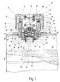
- the pressure relief valve device is designed as a two-stage pressure relief valve 10, which is integrated in an approximately cap-like closure cover 11, which has an integral cylinder neck 13 on an upper cover part 12, which is screwed onto the external thread 15 of a filler neck 16 with an internal thread 14.
- the filler neck 16 is firmly and tightly attached to an expansion tank 17, specifically where there is a certain air cushion 20 above the level 18 of the cooling liquid 19 in normal operation.
- the expansion tank 17 and also the filler neck 16 are e.g. made of plastic.
- the expansion tank 17 is connected in a conventional manner to the cooling circuit of a liquid-cooled internal combustion engine.
- the two-stage pressure relief valve 10 is able to operate at a first pressure level at operating pressure, e.g. when a pressure of about 0.6 bar is exceeded, and also when the pressure rises faster in a subsequent second pressure stage at an increased pressure, i.e. overpressure, e.g. in the order of magnitude above 1.2 bar , each open automatically to the environment or to a container and thus establish a connection between the latter and the expansion tank 17 for reducing pressure.
- the two-stage pressure relief valve 10 is closed, so that in this area the interior of the expansion tank 17 to the environment or to one Container is tightly closed.
- This tightness in this intermediate stage ensures that, in the case mentioned, a pressure increase up to the second pressure stage, for example in the order of magnitude above 1.2 bar, can take place, thus preventing any ejection and thus loss of the coolant from the cooling circuit.
- the opening points in the first pressure stage and in the second pressure stage can be determined and set fairly precisely, as well as the closing point after the first pressure stage has been exceeded and a closing stage lying between this and the second pressure stage has been reached.
- the two-stage pressure relief valve 10 is either, as shown, with its individual elements to be described loosely inserted into the filler neck 16 or, in another embodiment, not shown, held on the closure cap 11 and attached in such a way that it is screwed on and off with the closure cap 11 forms a unity.
- This training is advantageous, because then there is a complete part for screwing and unscrewing.
- the connection of the elements of the two-stage pressure relief valve 10 on the closure cover 11 takes place in a conventional manner, for example by means of a snap connection or in another positive and / or non-positive manner.
- the two-stage pressure relief valve 10 has a cylindrical guide sleeve 21 within the filler neck 16. At least one valve piston 22 is accommodated within the guide sleeve 21 and is guided in it so that it can slide up and down.
- a return spring 23 acts on the valve piston 22 in the form of a cylindrical helical spring which is supported at one end on the valve piston 22 and at the other end on the cover part 12 of the closure cover 11.
- the guide sleeve 21 carries, preferably in one piece with it, a radially inwardly projecting annular collar 24, which forms a valve seat 64 for the valve piston 22.
- the annular collar 24 carries a molded sealing ring 25, which in cross section has the shape of an outwardly open lip ring with two sealing lips 26 and 27 in the upper region, which encompass the annular collar 24.
- One sealing lip 26 extends beyond the valve seat 64 of the collar 24 and thus forms a seal in this area.
- the other sealing lip 27 covers the downwardly facing end face 28 of the collar 24 and forms a negative pressure compensation element there, which can lift down from the end face 28 and release openings 32 in the collar 24 in the case of underpressure within the expansion tank 17 and open against the overpressure in the expansion tank 17 Ring face 28 is pressed.
- the valve piston 22 is pressed against the sealing lip 26 by means of the return spring 23. It can be acted upon at the end face in the area of the annular surface 29 with the pressure of the cooling liquid in the cooling circuit and thus inside the expansion tank 17.
- valve piston 22 On its outside, the valve piston 22 has a plurality of, for example six, axial channels 30 which are arranged at equal circumferential angular distances from one another and which open out freely at both ends. It goes without saying that axial channels of this type can instead be provided on the facing inner side of the guide sleeve 21 alone or in addition thereto.
- the guide sleeve 21 has a collar 34 which protrudes radially outward therewith. On its underside, this forms a support surface 35 for placement on the free edge 36 of the filler neck 16, by means of a seal 37 to be arranged in between.
- the collar 34 contains on its upper side a plurality of radial channels 38 which open out radially inside and outside and e.g. consist of grooves or the like. Wells.
- the closure cover 11 carries on the inside of its cover part 12 one or more axial projections which press onto the collar 34 of the guide sleeve 21 from above, the projection here being e.g. an annular web 43, as shown, is possible or instead webs, pins or the like.
- On the inside of the cylinder neck 13 there are several, e.g. four channels 44, placed at equal circumferential angular distances from one another, are arranged in the form of grooves which open out at the free lower edge of the cylinder neck 13 with their end 45 there. In the upper region, the channels 44 are connected to one another in the vicinity of the upper cover part 12 and the web 43 via a circumferential inner annular groove 46 within the cylinder neck 13.
- the annular groove 46 runs in the axial region of the radial channels 38, which end at the ends in the annular groove 46, so that a connection between the radial channels 30 of the valve piston 22, the interior of the guide sleeve 21 and the external environment through the radial channels 38, the annular groove 46 and the channels 44 is created.
- the valve piston 22 is hollow on the inside. It contains at least one further inner piston 51 inside, which serves to limit the pressure in the first pressure stage.
- the inner piston 51 is seated with an end ring part 52 on a valve seat 47 of the valve piston 22 and forms a part of the end face acted upon by the pressure in the cooling circuit with a bottom part 53.
- the valve piston 22 has a passage inside the ring portion 52 of the inner piston 51 and associated valve seat 47 of the valve piston 22 controllable, the other end of which communicates with the environment or a container.
- the inner piston 51 is pressed by means of its own return spring 54 in the form of a cylindrical helical spring with its ring part 52 against the valve seat 47 of the valve piston 22 in the closed position and is thus kept closed in the first pressure stage, as shown in FIG. 1.
- the inner piston 51 also has a second valve surface 55 which, when the coolant pressure rises above the opening pressure of the first pressure stage, e.g. when reaching about 0.8 bar, which results in a displacement of the inner piston 51 relative to the valve piston 22 against the action of the return spring 54 in the opening direction, can be pressed against a seat 48 of the valve piston 22 while closing the passage.
- the inner piston 51 is designed as a shuttle valve body, which acts against the action of its own return spring 54 relative to the valve piston 22 between a first closed position, which is shown in FIG. 1 and which is assumed at a pressure of the cooling liquid below the first pressure level, between an open position, which is shown in FIG. 2 shows and which is assumed when the first pressure level is exceeded, for example at a pressure of 0.6 bar, and is movable in a second closed position, which is shown in FIGS. 3 and 4, in which the coolant pressure maintains the pressure in the open position, for example of o , 6 bar, and which is, for example, 0.8 bar and greater.
- the inner piston 51 can thus be moved from its closed position according to FIG.
- the second valve surface 55 interacts with the seat surface 48, closing this end of the passage between the valve piston 22 and the inner piston 51, so that the pressure relief valve 10 in 3 is tightly closed.
- this relative closed position between the inner piston 51 and the valve piston 22 is maintained, but here the valve piston 22 is moved against the action of the return spring 23 into its open position, in which its end face 29 from the associated valve seat 64 Annular collar 24, here in particular from the sealing lip 26, is lifted off, so that a passage to the axial channels 30 and thus into the interior of the guide sleeve 21 is created in this area and pressure can be reduced in this way.
- the inner piston 51 In this open position of the valve piston 22, the inner piston 51 is in the closed position relative to it.
- the return spring 54 of the inner piston 51 is supported on the one hand on the valve piston 22 and on the other hand on the inner piston 51. It can be adjustable, as is illustrated, for example by means of an adjustable abutment part 56, which is held on the inner piston 51 or, as shown, on the valve piston 22.
- the abutment part 56 consists, for example, of a threaded part which is adjustably held in a threaded bore 49 of the valve piston 22 and is designed, for example, as a threaded sleeve which is open at the bottom.
- the return spring 54 is expediently supported without friction or at least with little friction axially, for example via sliding elements, rolling elements or the like, not shown.
- the second valve surface 55 of the inner piston 51 is arranged on the axial side of the inner piston 51 pointing in the opening direction and is designed as an axial surface.
- the valve seat 48 of the valve piston 22 assigned to this valve surface 55 is also designed as an axial surface.
- the two surfaces 55 and 48 which cooperate for control, in particular sealing in the closed position according to FIG. 3, thus, as axial surfaces, ensure reliable tightness in this closed position of the inner piston 51 and a pressure increase in the cooling system up to the second pressure level of e.g. 1.2 bar, which prevents damage to the internal combustion engine and coolant ejection.
- the inner piston 51 is designed, for example, as a poppet valve. It has a valve plate 57 which forms axial valve surfaces 52 and 55 on its two axial sides, each of which has an associated valve seat with an axially opposite surface 47 or 48 of the valve body 22 forms, cooperates. Between each axial valve surface 52, 55 of the inner piston 51 on the one hand and the associated axial surface 47 or 48 of the valve piston 22 on the other hand, as the first exemplary embodiment according to FIGS. 1 to 4 shows, a sealing ring 58 or 59, for example an O-ring, can be used , arranged, which is arranged on or in one of these surfaces.
- the inner piston 51 ' differs from the first exemplary embodiment solely in that the sealing rings 58, 59 shown in the first exemplary embodiment can be omitted because the inner piston 51', in particular its valve plate 57 ', is made of sealing material, for example Plastic, rubber, hard rubber or the like exists, and therefore with its axial valve surfaces 52 ', 55' at the same time forms sealing surfaces and therefore sealing rings are unnecessary. Otherwise, the second exemplary embodiment according to FIG. 5 corresponds to the first in FIGS. 1 to 4.
- the inner piston 51 is guided axially relatively displaceably within the valve piston 22.
- the valve piston 22 is provided with a cylinder sleeve section 50, in which the inner piston 51 is guided axially relatively displaceably with a guide part 60.
- the guide part 60 can consist of axial projections, for example of two approximately axially diametrically opposed axial webs.
- the guide part 60 is designed as a cylinder sleeve which strives in the opening direction of the valve plate 57, ie upwards in FIGS. 1 to 4, from the valve plate 57 and which contains passages 61 in the wall near the valve plate 57, which passages with the Inside the guide part 60, in particular the cylinder sleeve, in connection.
- the guide part 60 in particular that Cylinder sleeve, forms part of the passage of the valve piston 22.
- the latter has at least one axial opening 39 which is connected to the interior of the guide part 60 of the inner piston 51, which is designed as a cylinder sleeve, and to the interior of the guide sleeve 21 and opens out towards the latter.
- the valve piston 22 can of course also have at least one radial opening.
- the axial opening 39 of the valve piston 22 is formed by an axial passage in the abutment part 56 which, for example, is at the same time a tool engagement surface for the rotational adjustment of the abutment part 56, for example is designed as a hexagon socket surface.
- the spring stiffness of the return spring 23 acting on the valve piston 22 is greater than the spring stiffness of the return spring 54 acting on the inner piston 51. Also adjustable return spring 23 is set so that the valve piston 22 is then moved into the open position shown in Fig. 4 when the pressure of the coolant exceeds the second pressure level, e.g. is greater than 1.2 bar.
- the valve piston 22 has an approximately cup-shaped housing part 40, in which the inner piston 51, in particular its valve plate 57, is accommodated and displaceable while leaving a radial annular space 62 in between.
- the cross section of the passage which is formed between the inner piston 51 and the valve piston 22 and, in the open position of the inner piston 51 according to FIG. 2, enables the pressure to be reduced through the interior of the valve piston 22, can be changed to change the throughput, for example by changing the cross section of the annular space 62.
- This enables quick and easy adaptation to the desired opening points and Closing points of the inner piston 51 possible.
- the change in cross-section of the annular space 62 can take place, for example, by changing the diameter of the valve plate 57 or the inside diameter of the approximately cup-shaped housing part 40.
- the approximately cup-shaped housing part 40 is adjoined by a cover part 33, which can thus be attached in one piece or firmly and tightly thereon and which carries the cylinder sleeve section 50 for guiding the guide part 60 and which also carries the axial seat surface 48 on the end face facing the valve plate 57 , which is assigned to the axial second valve surface 55.
- the bottom 31 of the pot-shaped housing part 40 contains an opening 81 which can be controlled by the valve plate 57.
- the cross section of the opening 81 can be changed to change the characteristic of the pressure relief valve 10, e.g. by means of attachable perforated diaphragms or the like.
- the bottom 31 of the valve piston 22 can be subjected to the pressure of the cooling liquid on the axial side facing away from the valve plate 57, including the surface area of the valve plate 57 which is located in the area of the opening 81.
- the described valve piston 22 and / or the inner piston 51 can be formed from plastic.
- the expansion tank 17 has a certain air cushion 20 above the level 18.
- This liquid level can correspond to a switched off internal combustion engine in the cold state.
- the pressure in the expansion tank 17 gradually increases as a result of heating of the cooling liquid 19.
- this operating pressure has reached a certain overpressure, for example 0.6 bar, the force acting on the inner piston 51 overcomes that of the return spring 54, so that the inner piston 51 relative to the still closed valve piston 22 into the open position shown in FIG. 2 is moved up by moving, the axial valve surface 52 of the valve plate 57 thus lifts off the valve seat 47 and an opening for the pressure reduction is created there.
- the pressure of the cooling liquid can thus equalize through the opening 81, the annular space 62, through the passages 61, through the axial opening 39, through the interior of the guide sleeve 21 and from this to the outside, since a connection of the interior of the Expansion tank 17 is created with the environment. Due to this connection of the interior of the expansion tank 17 with the environment, a further increase in pressure during operation is avoided. If, on the other hand, the pressure would continue to rise and, for example, would exceed the point predetermined by the return spring 54, which ensures the open position of the inner piston 51, for example, would rise to 0.8 bar, this results in a displacement of the inner piston 51 into the closed position according to FIG. 3.
- the inner piston 51 is first pressed against the force of its return spring 54 into the open position according to FIG. 2, in which passage is made possible and pressure can be reduced.
- a further pressure increase for example up to 0.8 bar, has shifted the inner piston 51 into the closed position according to FIG 3 results. If the pressure rises further than 0.8 bar, the inner piston 51 and the valve piston 22 remain in the closed position.
- a further rapid pressure increase for example up to a value of 1.2 bar
- the inner piston 51 is shifted into the closed position according to FIG. 3 and the valve piston 22 is shifted upwards against the action of the return spring 23 into the open position according to FIG. 4.
- the interior of the expansion tank is directly connected to the atmosphere via the axial channels 30, the annular groove 46 and the channels 44.
- This second pressure level is selected so that damage to the cooling system of the internal combustion engine is avoided.
- the pressure relief valve 10 is simple, compact, has small dimensions and consists of simple, inexpensive parts, e.g. by rotating inexpensive to produce rotary parts, for which otherwise inexpensive series parts can also be used. It is also advantageous that by changing the characteristics of the inner piston 51, the opening and closing points of the inner piston 51 can be quickly and easily adjusted to the respective requirements. A change in the characteristic, e.g. of the throughput in the open position between the inner piston 51 and the valve piston 22 is possible with simple means for adaptation to the respective application. In its second sealing position according to FIG. 3, the inner piston 51 ensures reliable tightness and enables the pressure in the cooling system to be increased to the second pressure level, e.g. up to 1.2 bar, which prevents coolant ejection.
- the second pressure level e.g. up to 1.2 bar
Abstract
Description
Die Erfindung bezieht sich auf eine Überdruckventileinrichtung für den Kühlkreislauf einer flüssigkeitsgekühlten Brennkraftmaschine der ansonsten im Oberbegriff des Anspruchs 1 definierten Art.The invention relates to a pressure relief valve device for the cooling circuit of a liquid-cooled internal combustion engine of the type otherwise defined in the preamble of claim 1.
Es ist üblich, den Kühlkreislauf einer flüssigkeitsgekühlten Brennkraftmaschine so abzusichern, daß während des Betriebes der Brennkraftmaschine der Druck im Kühlkreislauf auf einen Betriebsdruck begrenzt wird, wobei dieser Wert niedriger ist als derjenige bei heißgefahrener, stillstehender Brennkraftmaschine. Auch sieht man Ausgleichsbehälter vor, die durch Temperaturänderungen hervorgerufene Volumenänderungen der Kühlflüssigkeit ausgleichen sollen und einen Kühlmittelauswurf mit Kühlmittelverlust vermeiden sollen, der nach dem Abstellen der Brennkraftmaschine durch Dampfblasenbildung infolge eines Wärmestaus innerhalb der Brennkraftmaschine noch auftreten kann.It is customary to secure the cooling circuit of a liquid-cooled internal combustion engine in such a way that the pressure in the cooling circuit is limited to an operating pressure during operation of the internal combustion engine, this value being lower than that when the internal combustion engine is hot and at a standstill. There are also expansion tanks which are intended to compensate for changes in volume of the coolant caused by temperature changes and to avoid coolant ejection with loss of coolant which can still occur after the internal combustion engine has been switched off due to the formation of vapor bubbles as a result of heat build-up inside the internal combustion engine.
Bei einer bekannten Überdruckventileinrichtung (DE-OS 34 22 705) vereinigt das Überdruckventil in einem einzigen, direkt auf den Füllstutzen des Ausgleichsbehälters aufschraubbaren Element einerseits ein Überdruckventil zur Begrenzung des Betriebsdruckes und andererseits ein Überdruckventil zur Begrenzung des Höchstdruckes, um Schäden im Kühlsystem und Kühlflüssigkeitsverlust zu verhindern, in einem einzigen Ventil mit einem einzigen Ventilkolben, der eine Öffnungsstufe, eine sich daran anschließende Drosselstufe und eine sich daran anschließende weitere Öffnungsstufe bei Axialbeaufschlagung durch Axialverschiebung durchlaufen kann. Eine solche bekannte Überdruckventileinrichtung hat sich bewährt. Sie ist außerordentlich einfach, kostengünstig und besteht nur aus wenigen kostengünstigen Bauteilen. In der DE-OS 34 22 705 ist auch eine Alternativlösung angesprochen, wonach der Ventilkolben im Inneren einen Innenkolben enthält, zwischen dem und dem Ventilkolben Axialkanäle gebildet sind, die einen Durchlaß ermöglichen, der mittels eines Ringabsatzes am Innenkolben, der auf einem Ventilsitz des äußeren Ventilkolbens aufsitzt und mittels der Rückstellfeder daran angepreßt ist, steuerbar und zur Umgebung bzw. zum Behälter hin freigebbar ist. Dabei kann der Innenkolben als Hohlkolben ausgebildet sein, dessen Kolbenboden denjenigen des äußeren Ventilkolbens bildet und als Widerlager für die Rückstellfeder dient, die sich mit einem Ende an diesem Innenkolben und mit ihrem anderen Ende am Verschlußdeckel abstützt, wobei also für den Ventilkolben und den darin befindlichen Innenkolben eine einzige Rückstellfeder vorgesehen ist. Die bekannte Gestaltung ist einer Veränderung der Charakteristik des Innenkolbens, z.B. einer Veränderung des Öffnungspunktes, des Durchsatzes im geöffneten Zustand od.dgl., ohne zugleich mit einhergehende Veränderung der Charakteristik des das Überdruckventil bildenden Ventilkolbens nur schlecht zugänglich.In a known pressure relief valve device (DE-OS 34 22 705), the pressure relief valve is combined in a single screwable screw directly onto the filler neck of the expansion tank Element, on the one hand, a pressure relief valve to limit the operating pressure and, on the other hand, a pressure relief valve to limit the maximum pressure to prevent damage to the cooling system and loss of coolant, in a single valve with a single valve piston, which has an opening stage, an adjoining throttle stage and an adjoining further one Can pass through the axial opening stage by axial displacement. Such a known pressure relief valve device has proven itself. It is extremely simple, inexpensive and consists of only a few inexpensive components. In DE-OS 34 22 705 an alternative solution is also addressed, according to which the valve piston contains an inner piston inside, between which and the valve piston axial channels are formed, which allow a passage by means of a ring shoulder on the inner piston, which is on a valve seat of the outer Valve piston sits and is pressed against it by means of the return spring, is controllable and can be released to the environment or to the container. The inner piston can be designed as a hollow piston, the piston crown of which forms that of the outer valve piston and serves as an abutment for the return spring, which is supported at one end on this inner piston and at the other end on the closure cover, thus for the valve piston and the one located therein Inner piston a single return spring is provided. The known design is a change in the characteristic of the inner piston, for example a change in the opening point, the throughput in the open state or the like, without at the same time difficult to access without accompanying change in the characteristic of the valve piston forming the pressure relief valve.
Der Erfindung liegt die Aufgabe zugrunde, eine Überdruckventileinrichtung der im Oberbegriff des Anspruchs 1 genannten Art dahingehend zu verbessern, daß diese hinsichtlich des den Betriebsdruck steuernden Innenkolbens schnell und einfach einer Veränderung der Charakteristik und Anpassung an jeweils gewünschte Werte zugänglich ist, ohne daß dabei die Charakteristik des vom Ventilkolben gebildeten Überdruckventils verändert wird, wobei zugleich eine deutliche Trennung zwischen der ersten und zweiten Druckstufe ventilseitig erreichbar sein soll.The invention has for its object to improve a pressure relief valve device of the type mentioned in the preamble of claim 1 in such a way that it is quick and easy with regard to the inner piston controlling the operating pressure a change in the characteristic and adaptation to the desired values is accessible without changing the characteristic of the pressure relief valve formed by the valve piston, while at the same time a clear separation between the first and second pressure stage should be achievable on the valve side.
Die Aufgabe ist bei einer Überdruckventileinrichtung der im Oberbegriff des Anspruchs 1 definierten Gattung erfindungsgemäß durch die Merkmale im Kennzeichnungsteil des Anspruchs 1 gelöst. Dadurch, daß der den Betriebsdruck steuernde Innenkolben über eine eigene Rückstellfeder am Ventilkolben abgestützt ist, kann die Charakteristik dieses den Betriebsdruck steuernden Überdruckventils relativ schnell und einfach den jeweiligen Einzelwünschen des Benutzers angepaßt und verändert werden. So kann z.B. die Federcharakteristik der Rückstellfeder des Innenkolbens verändert werden und dadurch der Öffnungspunkt und der Schließpunkt des Innenkolbens verändert und jeweils an bestehende Bedürfnisse angepaßt werden. Auch läßt sich in der Öffnungsstellung des Innenkolbens der den Durchlaß zwischen diesem und dem Ventilkolben passierende Durchsatz relativ einfach und problemlos verändern und an bestehende Wünsche anpassen. Dadurch, daß der Innenkolben bei Überschreiten eines über dem Betriebsdruck liegenden Druckes gegen die Wirkung seiner Rückstellfeder relativ zum Ventilkolben in eine den Durchlaß wieder verschließende Schließstellung bewegt wird, ist mit einfachen Mitteln ein dichter Abschluß in dieser Schließstellung erreichbar und damit eine Druckerhöhung im Kühlsystem auf die zweite Druckstufe möglich und dadurch ein Kühlmittelauswurf verhindert.In a pressure relief valve device of the type defined in the preamble of claim 1, the object is achieved according to the invention by the features in the characterizing part of claim 1. Characterized in that the inner piston controlling the operating pressure is supported on the valve piston via its own return spring, the characteristic of this pressure control valve that controls the operating pressure can be adapted and changed relatively quickly and easily to the individual requirements of the user. For example, the spring characteristics of the return spring of the inner piston are changed and thereby the opening point and the closing point of the inner piston are changed and respectively adapted to existing needs. Also, in the open position of the inner piston, the throughput passing through the passage between it and the valve piston can be changed relatively easily and without problems and adapted to existing requirements. Characterized in that the internal piston is moved relative to the valve piston in a closed position again to close the passage when a pressure above the operating pressure is exceeded against the action of its return spring, a tight seal in this closed position can be achieved with simple means and thus a pressure increase in the cooling system on the second pressure stage possible and thereby prevents coolant ejection.
Weitere vorteilhafte Erfindungsmerkmale und Ausgestaltungen dazu ergeben sich aus den Ansprüchen 2 bis 29.Further advantageous features of the invention and refinements to this result from claims 2 to 29.
Es ist eine Überdruckventileinrichtung bekannt (DE-OS 32 11 449), die in zwei unterschiedlich hohen Druckstufen, und zwar in einer Stufe bei Betriebsdruck und in einer anderen Stufe bei demgegenüber erhöhtem Druck, jeweils selbsttätig zur Umgebung hin öffnet und zwei ineinandergeschachtelte Ventile aufweist, und zwar ein für normalen Betriebsdruck zuständiges Ventil und ferner ein für den Überdruck zuständiges Sicherheitsventil. Das den Betriebsdruck steuernde Ventil weist einen im Sicherheitsventil gegen eine eigene Rückstellfeder geführten Innenkolben auf, der normalerweise in Schließstellung gedrückt ist und keinen Durchlaß freigibt. Bei Überschreiten einer ersten Druckstufe wird der Innenkolben in Öffnungsrichtung verschoben und geöffnet. Bei Überschreiten des Druckes, der dieses Öffnen bewirkt, bleibt aber der Innenkolben in der geöffneten Stellung, so daß bei plötzlichem Druckanstieg die Gefahr des Auswurfs von Kühlflüssigkeit besteht.A pressure relief valve device is known (DE-OS 32 11 449), which automatically opens to the environment in two different pressure levels, namely one level at operating pressure and another level at higher pressure, and has two nested valves, one for normal operating pressure and one for overpressure responsible safety valve. The valve controlling the operating pressure has an inner piston which is guided in the safety valve against its own return spring and is normally pressed into the closed position and does not open any passage. If a first pressure level is exceeded, the inner piston is moved and opened in the opening direction. If the pressure that causes this opening is exceeded, however, the inner piston remains in the open position, so that there is a risk of ejection of coolant if the pressure suddenly increases.
Weitere Einzelheiten und Vorteile der Erfindung ergeben sich aus der nachfolgenden Beschreibung.Further details and advantages of the invention result from the following description.
Der vollständige Wortlaut der Ansprüche ist vorstehend allein zur Vermeidung unnötiger Wiederholungen nicht wiedergegeben, sondern statt dessen lediglich durch Nennung der Anspruchsnummern darauf Bezug genommen, wodurch jedoch alle diese Anspruchsmerkmale als an dieser Stelle ausdrücklich und erfindungswesentlich offenbart zu gelten haben. Dabei sind alle in der vorstehenden und folgenden Beschreibung erwähnten Merkmale sowie auch die allein aus der Zeichnung entnehmbaren Merkmale weitere Bestandteile der Erfindung, auch wenn sie nicht besonders hervorgehoben und insbesondere nicht in den Ansprüchen erwähnt sind.The full wording of the claims is not reproduced above solely in order to avoid unnecessary repetition, but instead is referred to only by mentioning the claim numbers, whereby all these features of the claim are to be regarded as being explicitly disclosed here and essential to the invention. All of the features mentioned in the above and the following description, as well as the features that can only be inferred from the drawing, are further components of the invention, even if they are not particularly emphasized and are not mentioned in the claims.
Die Erfindung ist nachfolgend anhand von in den Zeichnungen gezeigten Ausführungsbeispielen näher erläutert. Es zeigen:
- Fig. 1
- einen schematischen Schnitt einer Überdruckventileinrichtung und eines Teiles eines Ausgleichsbehälters für die Kühlflüssigkeit flüssigkeitsgekühlter Brennkraftmaschinen, auf den die Überdruckventileinrichtung aufgeschraubt ist, gemäß einem ersten Ausführungsbeispiel und dabei im Normalbetrieb und geschlossen,
- Fig. 2
- einen schematischen Schnitt eines Teils der Überdruckventileinrichtung in Fig. 1 in einer ersten Druckstufe bei in Öffnungsstellung befindlichem Innenkolben,
- Fig. 3
- einen schematischen Schnitt eines Teils der Überdruckventileinrichtung in Fig. 1 in einer Schließstellung des Innenkolbens bei über dessen Öffnungsdruck liegendem Druck,
- Fig. 4
- einen schematischen Schnitt eines Teils der Überdruckventileinrichtung in Fig. 1 in einer zweiten Druckstufe bei nach wie vor geschlossenem Innenkolben und zusammen mit diesem geöffnetem Ventilkolben,
- Fig. 5
- einen schematischen Schnitt eines Teils der Überdruckventileinrichtung gemäß einem zweiten Ausführungsbeispiel und dabei in der Fig. 1 entsprechenden Schließstellung.
- Fig. 1
- 2 shows a schematic section of a pressure relief valve device and a part of an expansion tank for the cooling liquid of liquid-cooled internal combustion engines, onto which the pressure relief valve device is screwed, according to a first embodiment and thereby in normal operation and closed,
- Fig. 2
- 2 shows a schematic section of part of the pressure relief valve device in FIG. 1 in a first pressure stage with the inner piston in the open position,
- Fig. 3
- 2 shows a schematic section of part of the pressure relief valve device in FIG. 1 in a closed position of the inner piston at a pressure above its opening pressure,
- Fig. 4
- 2 shows a schematic section of part of the pressure relief valve device in FIG. 1 in a second pressure stage with the inner piston still closed and together with the open valve piston,
- Fig. 5
- a schematic section of part of the pressure relief valve device according to a second embodiment and in this case corresponding in FIG. 1 closed position.
Die in den Zeichnungen gezeigte Überdruckventileinrichtung ist für den Kühlkreislauf einer flüssigkeitsgekühlten Brennkraftmaschine und dazu bestimmt, beim Betrieb der Brennkraftmaschine eine Druckbegrenzung auf einen Betriebsdruck, z.B. in der Größenordnung von 0,6 bar, und bei abgestellter Brennkraftmaschine eine Druckbegrenzung auf einen demgegenüber erhöhten Überdruck, z.B. in der Größenordnung von 1,2 bar, zu bewirken, wobei die Überdruckventileinrichtung ab einem dazwischenliegenden Druckbereich, z.B. in der Größenordnung ab 0,8 bar, bis zum Erreichen der zweiten Druckstufe, z.B. 1,2 bar, geschlossen bleiben soll.The pressure relief valve device shown in the drawings is intended for the cooling circuit of a liquid-cooled internal combustion engine and is intended to limit the pressure to an operating pressure, e.g. in the order of magnitude of 0.6 bar, and when the internal combustion engine is switched off, a pressure limitation to an overpressure which is higher than that, e.g. in the order of 1.2 bar, whereby the pressure relief valve device from an intermediate pressure range, e.g. in the order of magnitude from 0.8 bar until the second pressure stage is reached, e.g. 1.2 bar, should remain closed.
Die Überdruckventileinrichtung ist durch ein Mehrstufen-Überdruckventil gebildet, das in wesentlichen Elementen demjenigen gemäß DE-OS 34 22 705 entspricht, auf die hier zur Vermeidung unnötiger Wiederholungen verwiesen ist. Die Überdruckventileinrichtung ist als Zweistufen-Überdruckventil 10 ausgebildet, das in einen etwa kappenartigen Verschlußdeckel 11 integriert ist, der an einem oberen Deckelteil 12 einen damit einstückigen Zylinderhals 13 aufweist, der mit einem Innengewinde 14 auf das Außengewinde 15 eines Füllstutzens 16 aufgeschraubt ist. Der Füllstutzen 16 ist fest und dicht an einem Ausgleichsbehälter 17 befestigt, und zwar dort, wo sich im Normalbetrieb über dem Niveau 18 der Kühlflüssigkeit 19 ein bestimmtes Luftpolster 20 einstellt. Der Ausgleichsbehälter 17 und auch der Füllstutzen 16 bestehen z.B. aus Kunststoff.The pressure relief valve device is formed by a multi-stage pressure relief valve, which essentially corresponds to that according to DE-OS 34 22 705, to which reference is made here to avoid unnecessary repetitions. The pressure relief valve device is designed as a two-stage
Auch andere Gestaltungen, die in der DE-OS 34 22 705 erwähnt sind, liegen im Rahmen der Erfindung.Other designs that are mentioned in DE-OS 34 22 705 are also within the scope of the invention.
Der Ausgleichsbehälter 17 ist in herkömmlicher Weise mit dem Kühlkreislauf einer flüssigkeitsgekühlten Brennkraftmaschine verbunden. Das Zweistufen-Überdruckventil 10 ist in der Lage, in einer ersten Druckstufe bei Betriebsdruck, z.B. bei Überschreiten eines Druckes von etwa 0,6 bar, und außerdem bei schnellerem Druckanstieg in einer nächstfolgenden zweiten Druckstufe bei demgegenüber erhöhtem Druck, also Überdruck, z.B. in der Größenordnung über 1,2 bar, jeweils selbsttätig zur Umgebung hin oder zu einem Behältnis zu öffnen und damit eine Verbindung zwischen diesen und dem Ausgleichsbehälter 17 zum Druckabbau herzustellen. In einem Zwischenbereich zwischen der ersten Druckstufe und der zweiten Druckstufe hingegen, z.B. bei Erreichen eines Druckes von etwa 0,8 bar, ist das Zweistufen-Überdruckventil 10 hingegen geschlossen, so daß in diesem Bereich das Innere des Ausgleichsbehälters 17 zur Umgebung hin oder zu einem Behältnis dicht verschlossen ist. Durch diese Dichtheit in dieser Zwischenstufe ist gewährleistet, daß im genannten Fall eine Druckerhöhung bis zur zweiten Druckstufe z.B. in der Größenordnung über 1,2 bar erfolgen kann und somit ein etwaiger Auswurf und damit Verlust der Kühlflüssigkeit aus dem Kühlkreislauf verhindert ist. Die Öffnungspunkte in der ersten Druckstufe und in der zweiten Druckstufe sind ziemlich exakt festlegbar und festgelegt ebenso wie der Schließpunkt nach Überschreiten der ersten Druckstufe und Erreichen einer zwischen dieser und der zweiten Druckstufe liegenden Schließstufe.The
Das Zweistufen-Überdruckventil 10 ist entweder, wie gezeigt, mit seinen noch zu beschreibenden Einzelelementen lose in den Füllstutzen 16 eingesetzt oder bei einem anderen, nicht gezeigten Ausführungsbeispiel am Verschlußdeckel 11 gehalten und derart angebracht, daß es beim Auf- und Abschrauben des Verschlußdeckels 11 mit diesem eine Einheit bildet. Diese Ausbildung ist von Vorteil, da dann sich ein komplettes Teil zum Aufschrauben und Abschrauben ergibt. Die Verbindung der Elemente des Zweistufen-Überdruckventils 10 am Verschlußdeckel 11 geschieht in herkömmlicher Weise z.B. mittels einer Schnappverbindung oder in anderer formschlüssiger und/oder kraftschlüssiger Weise.The two-stage
Das Zweistufen-Überdruckventil 10 weist eine zylindrische Führungshülse 21 innerhalb des Füllstutzens 16 auf. Innerhalb der Führungshülse 21 ist zumindest ein Ventilkolben 22 aufgenommen, der darin auf und ab verschiebbar geführt ist. Auf den Ventilkolben 22 wirkt eine Rückstellfeder 23 in Form einer zylindrischen Schraubenfeder, die mit einem Ende am Ventilkolben 22 und mit ihrem anderen Ende am Deckelteil 12 des Verschlußdeckels 11 abgestützt ist. Am unteren Ende trägt die Führungshülse 21, vorzugsweise einstückig damit, einen radial nach innen vorspringenden Ringbund 24, der einen Ventilsitz 64 für den Ventilkolben 22 bildet. Der Ringbund 24 trägt einen Formdichtungsring 25, der im oberen Bereich im Querschnitt die Form eines nach außen offenen Lippenringes mit zwei Dichtlippen 26 und 27 hat, welche den Ringbund 24 umgreifen. Die eine Dichtlippe 26 erstreckt sich über den Ventilsitz 64 des Ringbundes 24 hinweg und bildet damit eine Dichtung in diesem Bereich. Die andere Dichtlippe 27 überdeckt die nach unten weisende Ringstirnfläche 28 des Ringbundes 24 und bildet dort ein Unterdruckausgleichselement, das bei Unterdruck innerhalb des Ausgleichsbehälters 17 von der Ringstirnfläche 28 nach unten abheben und Öffnungen 32 im Ringbund 24 freigeben kann und bei Überdruck im Ausgleichsbehälter 17 gegen die Ringstirnfläche 28 angepreßt ist. Der Ventilkolben 22 ist mittels der Rückstellfeder 23 an die Dichtlippe 26 angepreßt. Er ist stirnseitig im Bereich der Ringfläche 29 mit dem Druck der Kühlflüssigkeit im Kühlkreislauf und damit im Inneren des Ausgleichsbehälters 17 beaufschlagbar.The two-stage
Auf seiner Außenseite weist der Ventilkolben 22 mehrere, z.B. sechs, in gleichen Umfangswinkelabständen voneinander angeordnete Axialkanäle 30 auf, die beidendig frei ausmünden. Es versteht sich, daß statt dessen derartige Axialkanäle auch auf der zugewandten Innenseite der Führungshülse 21 allein oder zusätzlich dazu vorgesehen sein können.On its outside, the
Die Führungshülse 21 weist am in Fig. 1 oberen Ende einen damit einstückigen, radial nach außen auskragenden Bund 34 auf. Dieser bildet auf seiner Unterseite eine Auflagefläche 35 zum Aufsetzen auf den freien Rand 36 des Füllstutzens 16, unter Vermittlung einer dazwischen anzuordnenden Dichtung 37. Der Bund 34 enthält auf seiner Oberseite mehrere Radialkanäle 38, die radial innen und außen frei ausmünden und z.B. aus Nuten od. dgl. Vertiefungen bestehen.At the upper end in FIG. 1, the
Der Verschlußdeckel 11 trägt auf der Innenseite seines Deckelteils 12 einen oder mehrere axiale Vorsprünge, die auf den Bund 34 der Führungshülse 21 von oben her drücken, wobei als Vorsprung hier z.B. ein ringförmiger Steg 43, wie gezeigt, möglich ist oder statt dessen auch Stege, Stifte od. dgl. Auf der Innenseite des Zylinderhalses 13 sind mehrere, z.B. vier, in gleichen Umfangswinkelabständen voneinander plazierte Kanäle 44 in Form von Nuten angeordnet, die am freien unteren Rand des Zylinderhalses 13 mit ihrem dortigen Ende 45 frei nach außen ausmünden. Im oberen Bereich stehen die Kanäle 44 in der Nähe des oberen Deckelteiles 12 und des Steges 43 über eine umlaufende innere Ringnut 46 innerhalb des Zylinderhalses 13 miteinander in Verbindung. Die Ringnut 46 verläuft im Axialbereich der Radialkanäle 38, die mit ihren Enden in die Ringnut 46 münden, wodurch also eine Verbindung zwischen den Radialkanälen 30 des Ventilkolbens 22, dem Inneren der Führungshülse 21 und der äußeren Umgebung durch die Radialkanäle 38, die Ringnut 46 und die Kanäle 44 geschaffen ist.The closure cover 11 carries on the inside of its
Der Ventilkolben 22 ist innen hohl. Er enthält im Inneren mindestens einen weiteren Innenkolben 51, der der Druckbegrenzung in der ersten Druckstufe dient. Der Innenkolben 51 sitzt mit einem stirnseitigen Ringteil 52 auf einem Ventilsitz 47 des Ventilkolbens 22 auf und bildet mit einem Bodenteil 53 einen Teil der mit dem Druck im Kühlkreislauf beaufschlagten Stirnfläche. Der Ventilkolben 22 weist einen vom Ringteil 52 des Innenkolbens 51 und zugeordneten Ventilsitz 47 des Ventilkolbens 22 steuerbaren Durchlaß im Inneren auf, der mit seinem anderen Ende mit der Umgebung oder einem Behälter in Verbindung steht.The
Der Innenkolben 51 ist mittels einer eigenen Rückstellfeder 54 in Form einer zylindrischen Schraubenfeder mit seinem Ringteil 52 gegen den Ventilsitz 47 des Ventilkolbens 22 in Schließstellung gedrückt und auf diese Weise in der ersten Druckstufe geschlossen gehalten, wie Fig. 1 zeigt.The
Der Innenkolben 51 weist ferner eine zweite Ventilfläche 55 auf, die bei über den Öffnungsdruck der ersten Druckstufe ansteigendem Kühlflüssigkeitsdruck, z.B. bei Erreichen von etwa 0,8 bar, das eine Verschiebung des Innenkolbens 51 relativ zum Ventilkolben 22 gegen die Wirkung der Rückstellfeder 54 in Öffnungsrichtung zur Folge hat, gegen eine Sitzfläche 48 des Ventilkolbens 22 unter Verschließen des Durchlasses preßbar ist.The
Der Innenkolben 51 ist als Wechselventilkörper ausgebildet, der gegen die Wirkung der eigenen Rückstellfeder 54 relativ zum Ventilkolben 22 zwischen einer ersten Schließstellung, die Fig. 1 zeigt und bei einem Druck der Kühlflüssigkeit unterhalb der ersten Druckstufe eingenommen wird, zwischen einer Öffnungsstellung, die Fig. 2 zeigt und die bei Überschreiten der ersten Druckstufe, z.B. bei einem Druck von 0,6 bar,eingenommen wird, und einer zweiten Schließstellung bewegbar ist, die Fig. 3 und 4 zeigt, in der der Kühlflüssigkeitsdruck den die Öffnungsstellung beibehaltenden Druck z.B. von o,6 bar, überschreitet und der z.B. bei 0,8 bar und größer liegt. Der Innenkolben 51 ist somit bei Überschreiten eines ersten Druckes der Kühlflüssigkeit z.B. von 0,6 bar aus seiner Schließstellung gemäß Fig. 1 heraus in seine Öffnungsstellung bewegbar, in der er gehalten wird, wenn der Druck nicht über den Schließdruck des Innenkolbens 51 ansteigt, der z.B. bei 0,8 bar liegt. In dieser in Fig. 2 gezeigten Öffnungsstellung ist der im Inneren des Ventilkolbens 22 zwischen diesem und dem Innenkolben 51 gebildete und in das Innere der Führungshülse 21 ausmündende Durchlaß geöffnet, so daß darüber ein Druckabbau erfolgen kann.The
Hat der Innenkolben 51 die zweite Schließstellung eingenommen, die Fig. 3 und 4 zeigt, wirkt die zweite Ventilfläche 55 mit der Sitzfläche 48 unter Verschluß dieses Endes des Durchlasses zwischen dem Ventilkolben 22 und dem Innenkolben 51 zusammen, so daß also nun das Überdruckventil 10 in der Stellung gemäß Fig. 3 dicht geschlossen ist. Auch in der Stellung gemäß Fig. 4 bleibt diese relative Schließstellung zwischen dem Innenkolben 51 und dem Ventilkolben 22 erhalten, jedoch ist hier der Ventilkolben 22 gegen die Wirkung der Rückstellfeder 23 in seine Öffnungsstellung bewegt, in der dessen stirnseitige Ringfläche 29 vom zugeordneten Ventilsitz 64 des Ringbundes 24, hier insbesondere von der Dichtlippe 26, abgehoben ist, so daß in diesem Bereich ein Durchgang zu den Axialkanälen 30 und damit in das Innere der Führungshülse 21 geschaffen ist und auf diese Weise ein Druckabbau erfolgen kann. In dieser Öffnungsstellung des Ventilkolbens 22 ist der Innenkolben 51 relativ dazu in Schließstellung.3 and 4, the
Wie ersichtlich ist, ist die Rückstellfeder 54 des Innenkolbens 51 einerseits am Ventilkolben 22 und andererseits am Innenkolben 51 abgestützt. Sie kann einstellbar sein, wie verdeutlicht ist, z.B. mittels eines einstellbaren Widerlagerteils 56, das am Innenkolben 51 oder, wie gezeigt, am Ventilkolben 22 gehalten ist. Das Widerlagerteil 56 besteht z.B. aus einem Gewindeteil, das einstellbar in einer Gewindebohrung 49 des Ventilkolbens 22 gehalten und z.B. als nach unten offene Gewindehülse ausgebildet ist. Die Rückstellfeder 54 ist zweckmäßigerweise reibungsfrei oder zumindest reibungsarm axial abgestützt, z.B. über nicht gezeigte Gleitelemente, Rollkörper od. dgl. Dies hat den Vorteil, daß eine Einstellung der Rückstellfeder 54 durch Verdrehen des Widerlagerteiles 56 sehr feinfühlig und genau möglich ist, ohne daß eine Haftreibung zwischen den Abstützflächen und der Rückstellfeder 54 als etwaiger Fehler eingeht. Durch Verstellen des Widerlagerteiles 56 kann der Öffnungspunkt des Innenkolbens 51 schnell und einfach eingestellt und an die jeweiligen Wünsche angepaßt werden. Gleichermaßen kann auch der Schließpunkt des Innenkolbens 51 schnell und einfach und feinfühlig je nach Bedarf eingestellt und festgelegt werden.As can be seen, the
Ersichtlich ist die zweite Ventilfläche 55 des Innenkolbens 51 auf der in Öffnungsrichtung des Innenkolbens 51 weisenden Axialseite diesesangeordnet und als Axialfläche ausgebildet. Auch der dieser Ventilfläche 55 zugeordnete Ventilsitz 48 des Ventilkolbens 22 ist als Axialfläche ausgebildet. Die beiden zur Steuerung, insbesondere Abdichtung in der Schließstellung gemäß Fig. 3, zusammenwirkenden Flächen 55 und 48 gewährleisten somit als Axialflächen eine zuverlässige Dichtheit in dieser Schließstellung des Innenkolbens 51 und eine Druckerhöhung im Kühlsystem bis zur zweiten Druckstufe von z.B. 1,2 bar, wodurch Beschädigungen der Brennkraftmaschine und ein Kühlmittelauswurf verhindert sind.As can be seen, the
Der Innenkolben 51 ist z.B. als Tellerventil gestaltet. Er weist eine Ventilplatte 57 auf, die auf ihren beiden Axialseiten axiale Ventilflächen 52 und 55 bildet, von denen jede mit einer axial gegenüberstehenden Fläche 47 bzw. 48 des Ventilkörpers 22, die einen zugeordneten Ventilsitz bildet, zusammenwirkt. Zwischen jeder axialen Ventilfläche 52, 55 des Innenkolbens 51 einerseits und zugeordneten axialen Fläche 47 bzw. 48 des Ventilkolbens 22 andererseits kann, wie das erste Ausführungsbeispiel gemäß Fig. 1 bis 4 zeigt, jeweils ein Dichtungsring 58 bzw. 59, z.B. ein O-Ring, angeordnet sein, der an oder in einer dieser Flächen angeordnet ist.The
Beim in Fig. 5 gezeigten zweiten Ausführungsbeispiel unterscheidet sich der Innenkolben 51' vom ersten Ausführungsbeispiel allein dadurch, daß die beim ersten Ausführungsbeispiel gezeigten Dichtungsringe 58, 59 entfallen können, weil der Innenkolben 51', insbesondere dessen Ventilplatte 57', aus Dichtungsmaterial, beispielsweise aus Kunststoff, Gummi, Hartgummi od. dgl., besteht und deswegen mit seinen axialen Ventilflächen 52', 55' zugleich Dichtungsflächen bildet und daher Dichtungsringe entbehrlich sind. Ansonsten entspricht das zweite Ausführungsbeispiel gemäß Fig. 5 dem ersten in Fig. 1 bis 4.In the second exemplary embodiment shown in FIG. 5, the inner piston 51 'differs from the first exemplary embodiment solely in that the sealing rings 58, 59 shown in the first exemplary embodiment can be omitted because the inner piston 51', in particular its valve plate 57 ', is made of sealing material, for example Plastic, rubber, hard rubber or the like exists, and therefore with its axial valve surfaces 52 ', 55' at the same time forms sealing surfaces and therefore sealing rings are unnecessary. Otherwise, the second exemplary embodiment according to FIG. 5 corresponds to the first in FIGS. 1 to 4.
Der Innenkolben 51 ist innerhalb des Ventilkolbens 22 axial relativ verschieblich geführt. Hierzu ist der Ventilkolben 22 mit einem Zylinderhülsenabschnitt 50 versehen, in dem der Innenkolben 51 mit einem Führungsteil 60 axial relativ verschiebbar geführt ist. Der Führungsteil 60 kann aus axialen Vorsprüngen bestehen, z.B. aus zwei etwa diametral einander gegenüberliegenden Axialstegen. Beim gezeigten Ausführungsbeispiel ist der Führungsteil 60 als Zylinderhülse ausgebildet, die in Öffnungsrichtung der Ventilplatte 57, d.h. in Fig. 1 bis 4 nach oben hin, von der Ventilplatte 57 abstrebt und die nahe der Ventilplatte 57 in der Wandung Durchlässe 61 enthält, die mit dem Inneren des Führungsteils 60, insbesondere der Zylinderhülse, in Verbindung stehen. Dieses Innere ist zum Inneren des Ventilkolbens 22 hin geöffnet. DerFührungsteil 60, insbesondere die Zylinderhülse, bildet einen Teil des Durchlasses des Ventilkolbens 22. Letzterer weist zumindest eine axiale Öffnung 39 auf, die mit dem Inneren des als Zylinderhülse ausgebildeten Führungsteils 60 des Innenkolbens 51 und mit dem Innenraum der Führungshülse 21 verbunden ist und zu letzterem hin ausmündet. Statt der axialen Öffnung 39 kann der Ventilkolben 22 natürlich auch mindestens eine radiale Öffnung aufweisen. Beim gezeigten Ausführungsbeispiel ist die axiale Öffnung 39 des Ventilkolbens 22 durch einen axialen Durchlaß im Widerlagerteil 56 gebildet, der z.B. zugleich eine Werkzeugangriffsfläche zur Drehverstellung des Widerlagerteils 56 ist, z.B. als Innensechskantfläche ausgebildet ist.The
Die Federsteifigkeit der am Ventilkolben 22 angreifenden Rückstellfeder 23 ist größer bemessen als die Federsteifigkeit der auf den Innenkolben 51 wirkenden Rückstellfeder 54. Dabei ist die z.B. ebenfalls einstellbare Rückstellfeder 23 so eingestellt, daß der Ventilkolben 22 dann in die in Fig. 4 gezeigte Öffnungsstellung verschoben wird, wenn der Druck der Kühlflüssigkeit die zweite Druckstufe übersteigt, z.B. größer 1,2 bar ist.The spring stiffness of the
Wie ersichtlich ist, weist der Ventilkolben 22 einen etwa topfförmigen Gehäuseteil 40 auf, in dem der Innenkolben 51, insbesondere dessen Ventilplatte 57, unter Belassung eines radialen Ringraumes 62 dazwischen aufgenommen und verschiebbar ist. Der Querschnitt des Durchlasses, der zwischen dem Innenkolben 51 und dem Ventilkolben 22 gebildet ist und in der Öffnungsstellung des Innenkolbens 51 gemäß Fig. 2 den Druckabbau durch das Innere des Ventilkolbens 22 ermöglicht, kann zur Veränderung des Durchsatzes veränderbar sein, z.B. durch Verändern des Querschnittes des Ringraumes 62. Dadurch ist eine schnelle und einfache Anpassung an jeweils gewünschte Öffnungspunkte und Schließpunkte des Innenkolbens 51 möglich. Die Querschnittsänderung des Ringraumes 62 kann z.B. durch Verändern des Durchmessers der Ventilplatte 57 oder des Innendurchmessers des etwa topfförmigen Gehäuseteils 40 erfolgen.As can be seen, the
An das etwa topfförmige Gehäuseteil 40 schließt sich ein Deckelteil 33 an, der damit einstückig oder daran fest und dicht angebracht sein kann und der den Zylinderhülsenabschnitt 50 zur Führung des Führungsteils 60 trägt und der außerdem auf der der Ventilplatte 57 zugewandten Stirnseite die axiale Sitzfläche 48 trägt, die der axialen zweiten Ventilfläche 55 zugeordnet ist. Der Boden 31 des topfförmigen Gehäuseteils 40 enthält eine von der Ventilplatte 57 steuerbare Öffnung 81. Der Querschnitt der Öffnung 81 kann zur Veränderung der Charakteristik des Überdruckventils 10 veränderbar sein, z.B. mittels anbringbarer Lochblenden od. dgl. Der Boden 31 des Ventilkolbens 22 ist auf der Axialseite, die der Ventilplatte 57 abgewandt ist, mit dem Druck der Kühlflüssigkeit beaufschlagbar, einschließlich des Flächenbereichs der Ventilplatte 57, der sich im Bereich der Öffnung 81 befindet. Der beschriebene Ventilkolben 22 und/oder der Innenkolben 51 können aus Kunststoff gebildet sein.The approximately cup-shaped
Im dargestellten Zustand in Fig. 1 hat der Ausgleichsbehälter 17 über dem Niveau 18 ein bestimmtes Luftpolster 20. Dieser Flüssigkeitsstand kann einer abgestellten Brennkraftmaschine im kalten Zustand entsprechen. Nach Inbetriebnahme der Brennkraftmaschine steigt der Druck im Ausgleichsbehälter 17 infolge Erwärmung der Kühlflüssigkeit 19 allmählich an. Wenn dieser Betriebsdruck einen bestimmten Überdruck, beispielsweise 0,6 bar, erreicht hat, überwindet die auf den Innenkolben 51 wirkende Kraft diejenige der Rückstellfeder 54, so daß der Innenkolben 51 relativ zum nach wie vor geschlossenen Ventilkolben 22 in die in Fig. 2 gezeigte Öffnungsstellung durch Verschieben nach oben bewegt wird, wobei also die axiale Ventilfläche 52 der Ventilplatte 57 vom Ventilsitz 47 abhebt und dort eine Öffnung für den Druckabbau geschaffen ist. Der Druck der Kühlflüssigkeit kann sich somit durch die Öffnung 81, den Ringraum 62, durch die Durchlässe 61, durch die axiale Öffnung 39, durch das Innere der Führungshülse 21 und von diesem nach außen hin ausgleichen, da über diesen Weg eine Verbindung des Inneren des Ausgleichsbehälters 17 mit der Umgebung geschaffen ist. Aufgrund dieser Verbindung des Inneren des Ausgleichsbehälters 17 mit der Umgebung ist ein weiterer Druckanstieg im Betrieb vermieden. Würde der Druck demgegenüber weiter steigen und z.B. den die Öffnungsstellung des Innenkolbens 51 gewährleistenden, durch die Rückstellfeder 54 vorgegebenen Punkt überschreiten, z.B. auf 0,8 bar steigen, so hat dies eine Verschiebung des Innenkolbens 51 in die Schließsstellung gemäß Fig. 3 zur Folge.In the state shown in FIG. 1, the
Bei bestimmten Betriebszuständen, z.B. bei Betrieb von Brennkraftmaschinen in relativ warmer Umgebung, beispielsweise in tropischen Ländern, kommt es vor, daß sich nach Abstellen einer verhältnismäßig hochtemperierten, heißgefahrenen Brennkraftmaschine infolge eines Hitzestaus Dampfblasen in der Brennkraftmaschine bilden. Diese bewirken einen sehr schnellen Druckanstieg im Kühlsystem und normalerweise einen Auswurf von Kühlflüssigkeit 19 aus dem Ausgleichsbehälter 17 mit einhergehenden Verlusten an Kühlflüssigkeit 19.In certain operating conditions, e.g. When operating internal combustion engines in a relatively warm environment, for example in tropical countries, it happens that after a relatively high-temperature, hot-running internal combustion engine is turned off, vapor bubbles form in the internal combustion engine as a result of a heat build-up. These cause a very rapid increase in pressure in the cooling system and normally eject cooling liquid 19 from the
Dies ist nun durch das Überdruckventil 10 vermieden. Bei einem solchen raschen Druckanstieg wird der Innenkolben 51 gegen die Kraft seiner Rückstellfeder 54 zunächst in die Öffnungsstellung gemäß Fig. 2 gedrückt, in der ein Durchgang ermöglicht ist und ein Druckabbau erfolgen kann. Ein weiterer Druckanstieg, z.B. bis 0,8 bar, hat eine Verschiebung des Innenkolbens 51 in die Schließstellung gemäß Fig. 3 zur Folge. Bei einem weiteren Druckanstieg über 0,8 bar hinaus bleibt der Innenkolben 51 und auch weiterhin der Ventilkolben 22 in Schließstellung. Bei einem weiteren schnellen Druckanstieg, z.B. bis über einen Wert von 1,2 bar, wird der Innenkolben 51 in die Schließstellung gemäß Fig. 3 verschoben und der Ventilkolben 22 gegen die Wirkung der Rückstellfeder 23 in die Öffnungsstellung gemäß Fig. 4 nach oben verschoben. Dann ist das Innere des Ausgleichsbehälters direkt über die Axialkanäle 30, die Ringnut 46 und die Kanäle 44 mit der Atmosphäre verbunden. Diese zweite Druckstufe ist so gewählt, daß Schäden im Kühlsystem der Brennkraftmaschine vermieden werden.This is now avoided by the
Das Überdruckventil 10 ist einfach, kompakt, hat geringe Abmessungen und besteht aus einfachen, kostengünstig herstellbaren Teilen, z.B. durch Drehen kostengünstig herstellbaren Rotationsteilen, für die im übrigen auch kostengünstig verfügbare Serienteile verwendet werden können. Von Vorteil ist ferner, daß durch Verändern der Charakteristik des Innenkolbens 51 die Öffnungs- und Schließpunkte des Innenkolbens 51 schnell und einfach den jeweiligen Wünschen entsprechend eingestellt werden können. Auch ist eine Veränderung der Charakteristik, z.B. des Durchsatzes in der Öffnungsstellung zwischen dem Innenkolben 51 und dem Ventilkolben 22, mit einfachen Mitteln zur Anpassung an jeweilige Anwendungsfälle möglich. Der Innenkolben 51 gewährleistet in seiner zweiten Dichtstellung gemäß Fig. 3 eine zuverlässige Dichtheit und ermöglicht eine Druckerhöhung im Kühlsystem auf die zweite Druckstufe, z.B. bis 1,2 bar, wobei dadurch ein Kühlmittelauswurf verhindert ist.The
Claims (29)
dadurch gekennzeichnet,
daß der Innenkolben (51) mittels einer eigenen Rückstellfeder (54) mit seinem Ringteil (52) gegen den Ventilsitz (47) des Ventilkolbens (22) in Schließrichtung gedrückt und in der ersten Druckstufe geschlossen gehalten wird und eine zweite Ventilfläche (55) aufweist, die bei über den Öffnungsdruck der ersten Druckstufe ansteigendem Kühlflüssigkeitsdruck und dadurch relativ zum Ventilkolben (22) gegen die Rückstellfeder (54) in Öffnungsrichtung gedrücktem Innenkolben (51) gegen eine Sitzfläche (48) des Ventilkolbens (22) unter Verschließen des Durchlasses anpreßbar ist.Pressure relief valve device for the cooling circuit of a liquid-cooled internal combustion engine to limit the pressure during operation of the internal combustion engine and to limit a higher pressure, in particular when the internal combustion engine is switched off, with a multi-stage pressure relief valve (10) operating in at least two differently high pressure stages, which operates in a first pressure stage at operating pressure and in one the following second pressure stage, in contrast, preferably rapidly, increased pressure automatically opens to the environment or to a container, the multi-stage pressure relief valve (10) having a guide sleeve (21) and within the latter at least one guided therein and by means of a return spring (23) against a valve seat (64) of the guide sleeve (21) pressed valve piston (22) for pressure limitation in the second pressure stage, which can be acted upon at the end with the pressure in the cooling circuit, the guide sleeve (21) and / or the valve piston (22) have axial channels (30), the inlet of which is controlled by the valve piston (22) and the associated valve seat (64) and the outlet of which has a free connection to the environment or to the container, and wherein the valve piston (22) has at least one other inside Contains inner piston (51) for pressure limitation in the first pressure stage, which is seated with an end ring part (52) on a valve seat (47) of the valve piston (22) and forms a part of the surface that can be subjected to pressure in the cooling circuit with a bottom part (53) , wherein the valve piston (22) has a passage which can be controlled by the ring part (52) of the inner piston (51) and is associated with the valve seat (47) of the valve piston (22) and which at the other end is connected to the surroundings or the container,
characterized,
that the inner piston (51) is pressed with its own return spring (54) with its ring part (52) against the valve seat (47) of the valve piston (22) in the closing direction and kept closed in the first pressure stage and has a second valve surface (55), which can be pressed against a seat surface (48) of the valve piston (22) while closing the passage, when the coolant pressure rises above the opening pressure of the first pressure stage and thereby relative to the valve piston (22) against the return spring (54) in the opening direction.
dadurch gekennzeichnet,
daß der Innenkolben (51) als Wechselventilkörper ausgebildet ist, der gegen die Wirkung seiner Rückstellfeder (54) relativ zum Ventilkolben (22) zwischen einer ersten Schließstellung, einer Öffnungsstellung und einer zweiten Schließstellung bewegbar ist.Pressure relief valve device according to claim 1,
characterized,
that the inner piston (51) is designed as a shuttle valve body which, against the action of its return spring (54), is movable relative to the valve piston (22) between a first closed position, an open position and a second closed position.
dadurch gekennzeichnet,
daß der Innenkolben (51) bei Überschreiten eines ersten Druckes der Kühlflüssigkeit, z.B. von etwa 0,6 bar, aus seiner ersten Schließstellung heraus in seine Öffnungsstellung bewegbar ist.Pressure relief valve device according to claim 1 or 2,
characterized,
that the inner piston (51) can be moved out of its first closed position into its open position when a first pressure of the cooling liquid is exceeded, for example about 0.6 bar.
dadurch gekennzeichnet,
daß der Innenkolben (51) bei Überschreiten eines Öffnungsdruckes, z.B. von etwa 0,8 bar, aus seiner Öffnungsstellung heraus in seine zweite Schließstellung bewegbar ist.Pressure relief valve device according to one of claims 1 to 3,
characterized,
that the inner piston (51) can be moved out of its open position into its second closed position when an opening pressure is exceeded, for example about 0.8 bar.
dadurch gekennzeichnet,
daß die Rückstellfeder (54) des Innenkolbens (51) am Ventilkolben (22) einerseits und am Innenkolben (51) andererseits abgestützt ist.Pressure relief valve device according to one of claims 1 to 4,
characterized,
that the return spring (54) of the inner piston (51) is supported on the valve piston (22) on the one hand and on the inner piston (51) on the other hand.
dadurch gekennzeichnet,
daß die Rückstellfeder (54) des Innenkolbens (51) einstellbar ist, z.B. mittels eines verstellbaren Widerlagerteils (56) am Ventilkolben (22) oder am Innenkolben (51).Pressure relief valve device according to claim 5,
characterized,
that the return spring (54) of the inner piston (51) is adjustable, for example by means of an adjustable abutment part (56) on the valve piston (22) or on the inner piston (51).
dadurch gekennzeichnet,
daß die Rückstellfeder (54) reibungsfrei oder zumindest reibungsarm axial abgestützt ist, z.B. über Gleitelemente, Rollkörper od.dgl.Pressure relief valve device according to one of claims 1 to 6,
characterized,
that the return spring (54) is supported without friction or at least with little friction axially, for example via sliding elements, rolling elements or the like.
dadurch gekennzeichnet,
daß der Widerlagerteil (56) aus einem Gewindeteil gebildet ist, das einstellbar in einer Gewindebohrung (49) des Ventilkolbens (22) gehalten ist.Pressure relief valve device according to claim 6 or 7,
characterized,
that the abutment part (56) is formed from a threaded part which is adjustably held in a threaded bore (49) of the valve piston (22).
dadurch gekennzeichnet,
daß der Gewindeteil aus einer Gewindehülse besteht.Pressure relief valve device according to claim 8,
characterized,
that the threaded part consists of a threaded sleeve.
dadurch gekennzeichnet,
daß die zweite Ventilfläche (55) des Innenkolbens (51) auf der in Öffnungsrichtung des Innenkolbens (51) weisenden Axialseite dieses angeordnet und als Axialfläche ausgebildet ist.Pressure relief valve device according to one of claims 1 to 9,
characterized,
that the second valve surface (55) of the inner piston (51) is arranged on the axial side of the inner piston (51) pointing in the opening direction and is designed as an axial surface.
dadurch gekennzeichnet,
daß der Ventilsitz (48) des Ventilkolbens (22), der der zweiten Ventilfläche (55) des Innenkolbens (51) zugeordnet ist, als Axialfläche ausgebildet ist.Pressure relief valve device according to one of claims 1 to 10,
characterized,
that the valve seat (48) of the valve piston (22), which is assigned to the second valve surface (55) of the inner piston (51), is designed as an axial surface.
dadurch gekennzeichnet,
daß der Innenkolben (51) eine Ventilplatte (57) aufweist, die auf ihren beiden Axialseiten axiale Ventilflächen (52, 55) bildet, von denen jede mit einer axial gegenüberstehenden Fläche (47 bzw. 48) des Ventilkolbens (22), die einen zugeordneten Ventilsitz bildet, zusammenwirkt.Pressure relief valve device according to one of claims 1 to 11,
characterized,
that the inner piston (51) has a valve plate (57) which forms axial valve surfaces (52, 55) on its two axial sides, each of which has an axially opposing surface (47 or 48) of the valve piston (22), which is associated with one Valve seat forms, interacts.
dadurch gekennzeichnet,
daß zwischen jeder axialen Ventilfläche (52, 55) des Innenkolbens (51) einerseits und axialen Fläche (47, 48) des Ventilkolbens (22) andererseits eine Dichtung, z.B. ein Dichtungsring (58, 59), angeordnet ist.Pressure relief valve device according to one of claims 1 to 12,
characterized,
that between each axial valve surface (52, 55) of the inner piston (51) on the one hand and axial surface (47, 48) of the valve piston (22) on the other hand, a seal, for example a sealing ring (58, 59), is arranged.
dadurch gekennzeichnet,
daß der Innenkolben (51'), insbesondere dessen Ventilplatte (57'), aus Dichtungsmaterial, z.B. aus Kunststoff, Gummi, Hartgummi od.dgl., besteht und mit seinen axialen Ventilflächen (52', 55') zugleich Dichtungsflächen bildet.Pressure relief valve device according to one of claims 1 to 12,
characterized,
that the inner piston (51 '), in particular its valve plate (57'), made of sealing material, for example made of plastic, Rubber, hard rubber or the like., And with its axial valve surfaces (52 ', 55') also forms sealing surfaces.
dadurch gekennzeichnet,
daß der Innenkolben (51) innerhalb des Ventilkolbens (22) axial relativ verschieblich geführt ist.Pressure relief valve device according to one of claims 1 to 14,
characterized,
that the inner piston (51) inside the valve piston (22) is axially displaceably guided.
dadurch gekennzeichnet,
daß der Ventilkolben (22) einen Zylinderhülsenabschnitt (50) aufweist, in dem der Innenkolben (51) mit einem Führungsteil (60) dieses axial relativ verschieblich geführt ist.Pressure relief valve device according to one of claims 1 to 15,
characterized,
that the valve piston (22) has a cylinder sleeve section (50) in which the inner piston (51) is guided axially relatively displaceably with a guide part (60).
dadurch gekennzeichnet,
daß der Führungsteil (60) aus axialen Vorsprüngen oder aus einer Zylinderhülse besteht, die in Öffnungsrichtung von der Ventilplatte (57) abstreben.Pressure relief valve device according to claim 16,
characterized,
that the guide part (60) consists of axial projections or a cylinder sleeve which strive in the opening direction from the valve plate (57).
dadurch gekennzeichnet,
daß der Führungsteil (60), insbesondere die Zylinderhülse, nahe der Ventilplatte (57) Durchlässe (61) enthält, die mit dem Inneren des Führungsteils (60), insbesondere der Zylinderhülse, in Verbindung stehen, das zum Ventilkolben (22) hin geöffnet ist.Pressure relief valve device according to claim 17,
characterized,
that the guide part (60), in particular the cylinder sleeve, near the valve plate (57) contains passages (61) which are in communication with the interior of the guide part (60), in particular the cylinder sleeve, which is open towards the valve piston (22) .
dadurch gekennzeichnet,
daß der Führungsteil (60), insbesondere die Zylinderhülse, einen Teil des Durchlasses des Ventilkolbens (22) bildet.Pressure relief valve device according to claim 17 or 18,
characterized,
that the guide part (60), in particular the cylinder sleeve, forms part of the passage of the valve piston (22).
dadurch gekennzeichnet,
daß der Ventilkolben (22) zumindest eine axiale oder radiale Öffnung (39) aufweist, die mit dem Inneren des Führungsteils (60), insbesondere der Führungshülse, des Innenkolbens (51) in Verbindung steht und zur Führungshülse (21) hin ausmündet.Pressure relief valve device according to one of claims 1 to 19,
characterized,
that the valve piston (22) has at least one axial or radial opening (39) which communicates with the inside of the guide part (60), in particular the guide sleeve, of the inner piston (51) and opens out towards the guide sleeve (21).
dadurch gekennzeichnet,
daß die Öffnung (39) des Ventilkolbens (22) durch einen vorzugsweise axialen Durchlaß im Widerlagerteil (56) gebildet ist.Pressure relief valve device according to claim 20,
characterized,
that the opening (39) of the valve piston (22) is formed by a preferably axial passage in the abutment part (56).
dadurch gekennzeichnet,
daß die Federsteifigkeit der am Ventilkolben (22) angreifenden Rückstellfeder (23) größer bemessen ist als diejenige der Rückstellfeder (54) des Innenkolbens (51).Pressure relief valve device according to one of claims 1 to 21,
characterized,
that the spring stiffness of the return spring (23) acting on the valve piston (22) is greater than that of the return spring (54) of the inner piston (51).
dadurch gekennzeichnet,
daß die Rückstellfeder (23) des Ventilkolbens (22) und/oder die Rückstellfeder (54) des Innenkolbens (51) aus einer zylindrischen Schraubenfeder besteht.Pressure relief valve device according to one of claims 1 to 22,
characterized,
that the return spring (23) of the valve piston (22) and / or the return spring (54) of the inner piston (51) consists of a cylindrical coil spring.
dadurch gekennzeichnet,
daß der Ventilkolben (22) einen etwa topfförmigen Gehäuseteil (40) aufweist, in dem der Innenkolben (51), insbesondere dessen Ventilplatte (57), unter Belassung eines radialen Ringraumes (62) dazwischen aufgenommen und verschiebbar ist.Pressure relief valve device according to one of claims 1 to 23,
characterized,
that the valve piston (22) has an approximately cup-shaped housing part (40) in which the inner piston (51), in particular its valve plate (57), is accommodated and displaceable while leaving a radial annular space (62) in between.
dadurch gekennzeichnet,
daß der Querschnitt des Durchlasses zwischen dem Innenkolben (51) und dem Ventilkolben (22), z.B. der Querschnitt des Ringraumes (62), zur Veränderung des Öffnungspunktes des Innenkolbens (51) und/oder des Durchsatzes durch den Durchlaß veränderbar ist.Pressure relief valve device according to one of claims 1 to 24,
characterized,
that the cross section of the passage between the inner piston (51) and the valve piston (22), for example the cross section of the annular space (62), can be changed to change the opening point of the inner piston (51) and / or the throughput through the passage.
dadurch gekennzeichnet,
daß an dem etwa topfförmigen Gehäuseteil (40) ein Deckelteil (33) fest und dicht angebracht ist, der den Zylinderhülsenabschnitt (50) und auf der der Ventilplatte (57) zugewandten Stirnseite die letzterer (57) zugeordnete Sitzfläche (48) trägt.Pressure relief valve device according to claim 24 or 25,
characterized,
that on the approximately cup-shaped housing part (40) a cover part (33) is firmly and tightly attached, which carries the cylinder sleeve section (50) and on the end face facing the valve plate (57) the latter (57) associated with the seat surface (48).
dadurch gekennzeichnet,
daß der Boden (31) des topfförmigen Gehäuseteils (40) eine von der Ventilplatte (57) steuerbare Öffnung (81) enthält und auf der der Ventilplatte (57) abgewandten Axialseite (29) einschließlich des im Bereich der Öffnung (81) befindlichen Flächenteils der Ventilplatte (57) mit dem Druck der Kühlflüssigkeit beaufschlagbar ist.Pressure relief valve device according to one of claims 24 to 26,
characterized,
that the bottom (31) of the pot-shaped housing part (40) contains an opening (81) which can be controlled by the valve plate (57) and on the axial side (29) facing away from the valve plate (57), including the area part of the opening located in the region of the opening (81) Valve plate (57) can be acted upon by the pressure of the coolant.
dadurch gekennzeichnet,
daß der Querschnitt der Öffnung (81) des Ventilkolbens (22) veränderbar ist, z.B. mittels anbringbarer Lochblenden od.dgl.Pressure relief valve device according to claim 27,
characterized,
that the cross section of the opening (81) of the valve piston (22) can be changed, for example by means of attachable perforated diaphragms or the like.
dadurch gekennzeichnet,
daß der Ventilkolben (22) und/oder der Innenkolben (51) aus Kunststoff gebildet ist.Pressure relief valve device according to one of claims 1 to 28,
characterized,
that the valve piston (22) and / or the inner piston (51) is made of plastic.
Applications Claiming Priority (2)
| Application Number | Priority Date | Filing Date | Title |
|---|---|---|---|
| DE4121086 | 1991-06-26 | ||
| DE4121086A DE4121086A1 (en) | 1991-06-26 | 1991-06-26 | PRESSURE VALVE DEVICE FOR THE COOLING CIRCUIT OF A LIQUID-COOLED INTERNAL COMBUSTION ENGINE |
Publications (2)
| Publication Number | Publication Date |
|---|---|
| EP0520135A1 true EP0520135A1 (en) | 1992-12-30 |
| EP0520135B1 EP0520135B1 (en) | 1994-09-07 |
Family
ID=6434780
Family Applications (1)
| Application Number | Title | Priority Date | Filing Date |
|---|---|---|---|
| EP92101780A Expired - Lifetime EP0520135B1 (en) | 1991-06-26 | 1992-02-04 | Overpressure valve device for the cooling circuit of a water-cooled internal combustion engine |
Country Status (2)
| Country | Link |
|---|---|
| EP (1) | EP0520135B1 (en) |
| DE (2) | DE4121086A1 (en) |
Cited By (7)
| Publication number | Priority date | Publication date | Assignee | Title |
|---|---|---|---|---|
| WO1999028605A1 (en) * | 1997-12-03 | 1999-06-10 | Heinrich Reutter | Sealing cap |
| US6532910B2 (en) | 2001-02-20 | 2003-03-18 | Volvo Trucks North America, Inc. | Engine cooling system |
| US7152555B2 (en) | 2001-02-20 | 2006-12-26 | Volvo Trucks North America, Inc. | Engine cooling system |
| EP2105152A1 (en) | 2004-09-20 | 2009-09-30 | Medela Holding AG | Membrane pump with ventilation valve |
| CN101858450A (en) * | 2010-06-13 | 2010-10-13 | 上海乐高压缩机有限公司 | Safety valve |
| CN103032612A (en) * | 2012-12-12 | 2013-04-10 | 中国航天科技集团公司第六研究院第十一研究所 | Dual-opening-pressure dual-displacement safety valve |
| CN103363170A (en) * | 2012-04-06 | 2013-10-23 | 重庆博张机电设备有限公司 | Pressure regulating valve |
Citations (4)
| Publication number | Priority date | Publication date | Assignee | Title |
|---|---|---|---|---|
| US2147727A (en) * | 1936-09-03 | 1939-02-21 | Gen Motors Corp | Radiator cap |
| US2732971A (en) * | 1956-01-31 | Radiator caps | ||
| FR2529951A1 (en) * | 1982-07-08 | 1984-01-13 | Renault Vehicules Ind | DEVICE FOR PRESSURIZING THE COOLING CIRCUIT OF A THERMAL ENGINE |
| EP0388765A1 (en) * | 1989-03-23 | 1990-09-26 | B L A U GmbH | Fillercap for a reservoir neck |
Family Cites Families (2)
| Publication number | Priority date | Publication date | Assignee | Title |
|---|---|---|---|---|
| DE3211449C2 (en) * | 1982-03-27 | 1984-06-20 | Daimler-Benz Ag, 7000 Stuttgart | Radiator cap |
| DE3422705A1 (en) * | 1984-06-19 | 1985-12-19 | Kühlerfabrik Längerer & Reich GmbH & Co KG, 7024 Filderstadt | Pressure-relief valve arrangement for the cooling circuit of a liquid-cooled internal combustion engine |
-
1991
- 1991-06-26 DE DE4121086A patent/DE4121086A1/en active Granted
-
1992
- 1992-02-04 EP EP92101780A patent/EP0520135B1/en not_active Expired - Lifetime
- 1992-02-04 DE DE59200458T patent/DE59200458D1/en not_active Expired - Fee Related
Patent Citations (4)
| Publication number | Priority date | Publication date | Assignee | Title |
|---|---|---|---|---|
| US2732971A (en) * | 1956-01-31 | Radiator caps | ||
| US2147727A (en) * | 1936-09-03 | 1939-02-21 | Gen Motors Corp | Radiator cap |
| FR2529951A1 (en) * | 1982-07-08 | 1984-01-13 | Renault Vehicules Ind | DEVICE FOR PRESSURIZING THE COOLING CIRCUIT OF A THERMAL ENGINE |
| EP0388765A1 (en) * | 1989-03-23 | 1990-09-26 | B L A U GmbH | Fillercap for a reservoir neck |
Cited By (14)
| Publication number | Priority date | Publication date | Assignee | Title |
|---|---|---|---|---|
| WO1999028605A1 (en) * | 1997-12-03 | 1999-06-10 | Heinrich Reutter | Sealing cap |
| US6367644B1 (en) | 1997-12-03 | 2002-04-09 | Heinrich Reutter | Sealing cap |
| US6532910B2 (en) | 2001-02-20 | 2003-03-18 | Volvo Trucks North America, Inc. | Engine cooling system |
| US6886503B2 (en) | 2001-02-20 | 2005-05-03 | Volvo Trucks North America, Inc. | Engine cooling system |
| US7152555B2 (en) | 2001-02-20 | 2006-12-26 | Volvo Trucks North America, Inc. | Engine cooling system |
| US8512010B2 (en) | 2004-09-20 | 2013-08-20 | Medela Holding Ag | Membrane pump with bleed valve |
| CN101905043B (en) * | 2004-09-20 | 2012-07-18 | 美德乐控股公司 | Membrane pump with bleed valve |
| EP2105152A1 (en) | 2004-09-20 | 2009-09-30 | Medela Holding AG | Membrane pump with ventilation valve |
| US9644622B2 (en) | 2004-09-20 | 2017-05-09 | Medela Holding Ag | Membrane pump with air release valve |
| CN101858450A (en) * | 2010-06-13 | 2010-10-13 | 上海乐高压缩机有限公司 | Safety valve |
| CN103363170A (en) * | 2012-04-06 | 2013-10-23 | 重庆博张机电设备有限公司 | Pressure regulating valve |
| CN103363170B (en) * | 2012-04-06 | 2015-08-19 | 重庆博张机电设备有限公司 | Pressure regulator valve |
| CN103032612A (en) * | 2012-12-12 | 2013-04-10 | 中国航天科技集团公司第六研究院第十一研究所 | Dual-opening-pressure dual-displacement safety valve |
| CN103032612B (en) * | 2012-12-12 | 2015-04-08 | 中国航天科技集团公司第六研究院第十一研究所 | Dual-opening-pressure dual-displacement safety valve |
Also Published As
| Publication number | Publication date |
|---|---|
| DE59200458D1 (en) | 1994-10-13 |
| DE4121086A1 (en) | 1993-01-14 |
| DE4121086C2 (en) | 1993-05-19 |
| EP0520135B1 (en) | 1994-09-07 |
Similar Documents
| Publication | Publication Date | Title |
|---|---|---|
| EP0686763B1 (en) | Fuel injection valve for internal combustion engines | |
| DE2056072A1 (en) | Thermostatically controlled mixing valve for hot and cold water | |
| DE3535953A1 (en) | FUEL INJECTION NOZZLE ARRANGEMENT | |
| EP1303687B1 (en) | Closure cap provided with anti-twisting | |
| EP1468172A1 (en) | Sealing lid for motor vehicle radiator | |
| DE3831554C2 (en) | Throttle check valve | |
| DE19602796B4 (en) | Control valve for small flow | |
| EP0520135B1 (en) | Overpressure valve device for the cooling circuit of a water-cooled internal combustion engine | |
| DE10034761A1 (en) | Sealing cap, e.g. for vehicle radiator; has valve arrangement with single valve body to open or shut flow connections according to three threshold levels of radiator inner pressure | |
| DE2726411A1 (en) | FUEL PISTON INJECTION PUMP | |
| DE2515019A1 (en) | CONTROL DEVICE | |
| DE3529614C2 (en) | ||
| EP1402157B1 (en) | Sealing cover with an anti-unscrew safety device | |
| EP1264087B1 (en) | Sealing cap | |
| EP0460299A1 (en) | Pressure control valve for oil-injection moulding nozzle for internal combustion engine | |
| DE2522443A1 (en) | Water valve with two seats, one for high pressure - preventing exit of water in case of leaks or detachment of hose | |
| DE3422705A1 (en) | Pressure-relief valve arrangement for the cooling circuit of a liquid-cooled internal combustion engine | |
| DE19732885B4 (en) | Cover with safety lock for a container | |
| EP1120553B1 (en) | Valve, especially a thermostatic valve | |
| DE1775351A1 (en) | Bottom valve for a hydraulic shock absorber | |
| DE3002361C2 (en) | ||
| DE1550468A1 (en) | Pressure control valve | |
| DE3803166A1 (en) | Pressure relief valve device for the cooling circuit of a liquid-cooled internal combustion engine | |
| AT228580B (en) | Automatic shut-off valve with remote control device | |
| DE2306220A1 (en) | CONTROL VALVE AND SAFETY VALVE EQUIPPED WITH IT |
Legal Events
| Date | Code | Title | Description |
|---|---|---|---|
| PUAI | Public reference made under article 153(3) epc to a published international application that has entered the european phase |
Free format text: ORIGINAL CODE: 0009012 |
|
| AK | Designated contracting states |
Kind code of ref document: A1 Designated state(s): DE FR GB IT |
|
| 17P | Request for examination filed |
Effective date: 19930129 |
|
| 17Q | First examination report despatched |
Effective date: 19931026 |
|
| GRAA | (expected) grant |
Free format text: ORIGINAL CODE: 0009210 |
|
| AK | Designated contracting states |
Kind code of ref document: B1 Designated state(s): DE FR GB IT |
|
| GBT | Gb: translation of ep patent filed (gb section 77(6)(a)/1977) |
Effective date: 19940909 |
|
| REF | Corresponds to: |
Ref document number: 59200458 Country of ref document: DE Date of ref document: 19941013 |
|
| ITF | It: translation for a ep patent filed |
Owner name: MODIANO & ASSOCIATI S.R.L. |
|
| ET | Fr: translation filed | ||
| PLBE | No opposition filed within time limit |
Free format text: ORIGINAL CODE: 0009261 |
|
| STAA | Information on the status of an ep patent application or granted ep patent |
Free format text: STATUS: NO OPPOSITION FILED WITHIN TIME LIMIT |
|
| 26N | No opposition filed | ||
| REG | Reference to a national code |
Ref country code: GB Ref legal event code: IF02 |
|
| PGFP | Annual fee paid to national office [announced via postgrant information from national office to epo] |
Ref country code: GB Payment date: 20020111 Year of fee payment: 11 |
|
| PGFP | Annual fee paid to national office [announced via postgrant information from national office to epo] |
Ref country code: FR Payment date: 20020221 Year of fee payment: 11 |
|
| PGFP | Annual fee paid to national office [announced via postgrant information from national office to epo] |
Ref country code: DE Payment date: 20020228 Year of fee payment: 11 |
|
| PG25 | Lapsed in a contracting state [announced via postgrant information from national office to epo] |
Ref country code: GB Free format text: LAPSE BECAUSE OF NON-PAYMENT OF DUE FEES Effective date: 20030204 |
|
| PG25 | Lapsed in a contracting state [announced via postgrant information from national office to epo] |
Ref country code: DE Free format text: LAPSE BECAUSE OF NON-PAYMENT OF DUE FEES Effective date: 20030902 |
|
| GBPC | Gb: european patent ceased through non-payment of renewal fee | ||
| PG25 | Lapsed in a contracting state [announced via postgrant information from national office to epo] |
Ref country code: FR Free format text: LAPSE BECAUSE OF NON-PAYMENT OF DUE FEES Effective date: 20031031 |
|
| REG | Reference to a national code |
Ref country code: FR Ref legal event code: ST |
|
| PG25 | Lapsed in a contracting state [announced via postgrant information from national office to epo] |
Ref country code: IT Free format text: LAPSE BECAUSE OF NON-PAYMENT OF DUE FEES Effective date: 20050204 |