EP0521532A1 - Apparatus for splicing a replacement web to a moving web - Google Patents
Apparatus for splicing a replacement web to a moving web Download PDFInfo
- Publication number
- EP0521532A1 EP0521532A1 EP92114262A EP92114262A EP0521532A1 EP 0521532 A1 EP0521532 A1 EP 0521532A1 EP 92114262 A EP92114262 A EP 92114262A EP 92114262 A EP92114262 A EP 92114262A EP 0521532 A1 EP0521532 A1 EP 0521532A1
- Authority
- EP
- European Patent Office
- Prior art keywords
- web
- reel
- leader
- replacement
- moving
- Prior art date
- Legal status (The legal status is an assumption and is not a legal conclusion. Google has not performed a legal analysis and makes no representation as to the accuracy of the status listed.)
- Granted
Links
- 239000000853 adhesive Substances 0.000 claims abstract description 13
- 230000001070 adhesive effect Effects 0.000 claims abstract description 13
- 239000004820 Pressure-sensitive adhesive Substances 0.000 claims description 4
- 238000011144 upstream manufacturing Methods 0.000 claims description 3
- 238000004806 packaging method and process Methods 0.000 description 12
- 230000005540 biological transmission Effects 0.000 description 6
- 239000003550 marker Substances 0.000 description 4
- 238000002360 preparation method Methods 0.000 description 4
- 239000002390 adhesive tape Substances 0.000 description 3
- 238000010276 construction Methods 0.000 description 2
- 238000000034 method Methods 0.000 description 2
- 239000005022 packaging material Substances 0.000 description 2
- 238000007789 sealing Methods 0.000 description 2
- 230000000153 supplemental effect Effects 0.000 description 2
- 229920000298 Cellophane Polymers 0.000 description 1
- 239000004743 Polypropylene Substances 0.000 description 1
- 235000019504 cigarettes Nutrition 0.000 description 1
- 238000001514 detection method Methods 0.000 description 1
- 238000006073 displacement reaction Methods 0.000 description 1
- 239000000284 extract Substances 0.000 description 1
- 239000000463 material Substances 0.000 description 1
- -1 polypropylene Polymers 0.000 description 1
- 229920001155 polypropylene Polymers 0.000 description 1
- 238000003825 pressing Methods 0.000 description 1
- 238000005096 rolling process Methods 0.000 description 1
- 238000003860 storage Methods 0.000 description 1
- 239000000758 substrate Substances 0.000 description 1
Images


Classifications
-
- B—PERFORMING OPERATIONS; TRANSPORTING
- B65—CONVEYING; PACKING; STORING; HANDLING THIN OR FILAMENTARY MATERIAL
- B65H—HANDLING THIN OR FILAMENTARY MATERIAL, e.g. SHEETS, WEBS, CABLES
- B65H19/00—Changing the web roll
- B65H19/10—Changing the web roll in unwinding mechanisms or in connection with unwinding operations
- B65H19/18—Attaching, e.g. pasting, the replacement web to the expiring web
- B65H19/1857—Support arrangement of web rolls
- B65H19/1868—The roll support being of the turret type
-
- B—PERFORMING OPERATIONS; TRANSPORTING
- B65—CONVEYING; PACKING; STORING; HANDLING THIN OR FILAMENTARY MATERIAL
- B65H—HANDLING THIN OR FILAMENTARY MATERIAL, e.g. SHEETS, WEBS, CABLES
- B65H19/00—Changing the web roll
- B65H19/10—Changing the web roll in unwinding mechanisms or in connection with unwinding operations
- B65H19/18—Attaching, e.g. pasting, the replacement web to the expiring web
- B65H19/1805—Flying splicing, i.e. the expiring web moving during splicing contact
- B65H19/1826—Flying splicing, i.e. the expiring web moving during splicing contact taking place at a distance from the replacement roll
- B65H19/1831—Flying splicing, i.e. the expiring web moving during splicing contact taking place at a distance from the replacement roll the replacement web being stationary prior to splicing contact
-
- B—PERFORMING OPERATIONS; TRANSPORTING
- B65—CONVEYING; PACKING; STORING; HANDLING THIN OR FILAMENTARY MATERIAL
- B65H—HANDLING THIN OR FILAMENTARY MATERIAL, e.g. SHEETS, WEBS, CABLES
- B65H19/00—Changing the web roll
- B65H19/10—Changing the web roll in unwinding mechanisms or in connection with unwinding operations
- B65H19/18—Attaching, e.g. pasting, the replacement web to the expiring web
- B65H19/1805—Flying splicing, i.e. the expiring web moving during splicing contact
- B65H19/1826—Flying splicing, i.e. the expiring web moving during splicing contact taking place at a distance from the replacement roll
- B65H19/1836—Flying splicing, i.e. the expiring web moving during splicing contact taking place at a distance from the replacement roll the replacement web being accelerated or running prior to splicing contact
-
- B—PERFORMING OPERATIONS; TRANSPORTING
- B65—CONVEYING; PACKING; STORING; HANDLING THIN OR FILAMENTARY MATERIAL
- B65H—HANDLING THIN OR FILAMENTARY MATERIAL, e.g. SHEETS, WEBS, CABLES
- B65H19/00—Changing the web roll
- B65H19/22—Changing the web roll in winding mechanisms or in connection with winding operations
- B65H19/29—Securing the trailing end of the wound web to the web roll
-
- B—PERFORMING OPERATIONS; TRANSPORTING
- B65—CONVEYING; PACKING; STORING; HANDLING THIN OR FILAMENTARY MATERIAL
- B65H—HANDLING THIN OR FILAMENTARY MATERIAL, e.g. SHEETS, WEBS, CABLES
- B65H2301/00—Handling processes for sheets or webs
- B65H2301/40—Type of handling process
- B65H2301/41—Winding, unwinding
- B65H2301/414—Winding
- B65H2301/4144—Finishing winding process
- B65H2301/41441—Finishing winding process and blocking outer layers against falling apart
- B65H2301/41442—Specified by the sealing medium sealing used
- B65H2301/414427—Heating or use of thermoplastic material
-
- B—PERFORMING OPERATIONS; TRANSPORTING
- B65—CONVEYING; PACKING; STORING; HANDLING THIN OR FILAMENTARY MATERIAL
- B65H—HANDLING THIN OR FILAMENTARY MATERIAL, e.g. SHEETS, WEBS, CABLES
- B65H2301/00—Handling processes for sheets or webs
- B65H2301/40—Type of handling process
- B65H2301/41—Winding, unwinding
- B65H2301/415—Unwinding
- B65H2301/41505—Preparing unwinding process
- B65H2301/41508—Preparing unwinding process the web roll being in the unwinding support / unwinding location
- B65H2301/41509—Preparing unwinding process the web roll being in the unwinding support / unwinding location opening web roll and related steps
- B65H2301/415095—Preparing unwinding process the web roll being in the unwinding support / unwinding location opening web roll and related steps gripping an edge of the web, e.g. by clamping and forward it, e.g. to splicing web advancing unit
-
- B—PERFORMING OPERATIONS; TRANSPORTING
- B65—CONVEYING; PACKING; STORING; HANDLING THIN OR FILAMENTARY MATERIAL
- B65H—HANDLING THIN OR FILAMENTARY MATERIAL, e.g. SHEETS, WEBS, CABLES
- B65H2301/00—Handling processes for sheets or webs
- B65H2301/40—Type of handling process
- B65H2301/46—Splicing
- B65H2301/461—Processing webs in splicing process
- B65H2301/4611—Processing webs in splicing process before splicing
- B65H2301/46115—Processing webs in splicing process before splicing by bringing leading edge to splicing station, e.g. by chain or belt
-
- B—PERFORMING OPERATIONS; TRANSPORTING
- B65—CONVEYING; PACKING; STORING; HANDLING THIN OR FILAMENTARY MATERIAL
- B65H—HANDLING THIN OR FILAMENTARY MATERIAL, e.g. SHEETS, WEBS, CABLES
- B65H2301/00—Handling processes for sheets or webs
- B65H2301/40—Type of handling process
- B65H2301/46—Splicing
- B65H2301/464—Splicing effecting splice
- B65H2301/4641—Splicing effecting splice by pivoting element
-
- B—PERFORMING OPERATIONS; TRANSPORTING
- B65—CONVEYING; PACKING; STORING; HANDLING THIN OR FILAMENTARY MATERIAL
- B65H—HANDLING THIN OR FILAMENTARY MATERIAL, e.g. SHEETS, WEBS, CABLES
- B65H2301/00—Handling processes for sheets or webs
- B65H2301/40—Type of handling process
- B65H2301/46—Splicing
- B65H2301/464—Splicing effecting splice
- B65H2301/46412—Splicing effecting splice by element moving in a direction perpendicular to the running direction of the web
-
- B—PERFORMING OPERATIONS; TRANSPORTING
- B65—CONVEYING; PACKING; STORING; HANDLING THIN OR FILAMENTARY MATERIAL
- B65H—HANDLING THIN OR FILAMENTARY MATERIAL, e.g. SHEETS, WEBS, CABLES
- B65H2301/00—Handling processes for sheets or webs
- B65H2301/40—Type of handling process
- B65H2301/46—Splicing
- B65H2301/464—Splicing effecting splice
- B65H2301/46414—Splicing effecting splice by nipping rollers
- B65H2301/464145—Splicing effecting splice by nipping rollers at least one of the rollers having additional feature, eg. knife or at least partly non-cylindrical shape
-
- B—PERFORMING OPERATIONS; TRANSPORTING
- B65—CONVEYING; PACKING; STORING; HANDLING THIN OR FILAMENTARY MATERIAL
- B65H—HANDLING THIN OR FILAMENTARY MATERIAL, e.g. SHEETS, WEBS, CABLES
- B65H2801/00—Application field
- B65H2801/81—Packaging machines
Definitions
- This invention relates to apparatus for splicing a replacement web to a moving web used in automatic packaging equipment.
- Relatively thin, soft packaging material such as cellophane, polypropylene, etc.
- the packaging material is usually supplied in the form of a web which moves from a storage reel, on which the web is spooled, along a predetermined path to the packaging equipment in accordance with the operation of a feed roller.
- the reel becomes empty, the web in a replacement reel is fed, usually by hand, into the feed roller, so that the operation of the packaging equipment can continue.
- the present invention provides an apparatus for splicing a replacement web to a moving web, comprising:
- FIG. 1 Before describing the apparatus of the present invention in detail, reference is made to Fig. 1 for the purpose of providing a brief overview of the apparatus.
- reference numerals B1, B2 represent reel or bobbin holders having respective shafts d1, d2 for holding reels R1, R2 of a web material that is to be furnished to an automatic packaging machine (not shown).
- Reel R1 on holder B1 supplies web r1 along a predetermined path a1 by reason of vertical guide D and horizontal guide G to gripper roller 1' and delivery roller 2 before web r1 engages rollers 3 leading to an automated packaging line (not shown).
- a marker may be provided on the web near its connection with the hub d1 of the reel for the purpose of indicating when the reel is about to be exhausted.
- a detector (not shown) detects this marker and actuates cutter 10 for the purpose of severing the moving web in preparation for splicing the leader edge of a replacement web to the trailing edge of the original web.
- Figs. 10 and 11 for the purpose of showing how web r1, as drawn to the packaging equipment, travels along guide G until the trailing edge engages gripper roll 1'.
- the leading edge of a replacement web partially overlies and is attached to pressure-sensitive tape n releasably held on gripper roller 1; and the gripper rollers 1, 1' move relative to each other so that, as shwon in Fig. 11, the trailing end of the moving web and tape n are sandwiched between the gripper rollers.
- This sandwiching action presses the moving web into engagement with adhesive on the surface of tape n thereby splicing web r2 to web r1 while web r1 is moving.
- the apparatus of the present invention includes guides D, D' associated with the respective reels. These guides direct the respective webs along separate L-shaped paths each having legs defined by guides G, G' that terminates in gripper rollers 1, 1' whose axes are parallel to each other but perpendicular to the path of movement of webs r1, r2.
- the guides are constructed and arranged So that the leg of one path, namely guide G is aligned with the leg, namely guide G', of the other path, and the gripper rollers are adjacent each other. Because the L-shaped paths guides of the invention are identical, only the left path shown in Fig. 1 is described in detail.
- tension lever 33 which is pivotally mounted on the frame and carries rotatable tensions rollers 34, 35.
- Rigidly attached to tension lever 33 is a cam that engages the free end of brake arm 6a which is pivotally mounted on the frame and includes brake 6 that carries a brake shoe frictionally engageable with reel R1 mounted.
- left tension lever 33 maintains a tension on web r1 as brake 6 engages the reel allowing moving web r1 to be unspooled from this reel without looping.
- tension lever 33 is rotated to the position shown in chain lines, the brake is released freeing the reel for movement
- an actuator moves driving roller 5 into engagement with the periphery of holder B1 for the purpose of rewinding the remnant of the web attached to the reel after cutter 10 has severed the web.
- an actuator is operated for the purpose of moving windback lever 7 into the position shown in Fig. 2 such that an electrically heated pad on the free end of lever 7 engages the web wound onto the hub of reel R1 thereby sealing the web remnant to itself and preventing its unwinding.
- the reel may now be removed from the apparatus and replaced by a fresh, full reel in preparation for its use in the manner described below.
- driving roller 5' can be positioned to engage holder B2 for the purpose of rewinding a web remnant onto reel R2 when that reel becomes exhausted.
- the windback lever 7 can be flipped to the right side as shown in Fig. 2 for the purpose of having an electrical heater engage the periphery of the web on reel R2 thus sealing the web to itself.
- reel R2 When reel R1 is supplying web to the packaging equipment in the manner shown in Fig. 1, reel R2 is a replacement reel carrying replacement web r2, the free end of which will be spliced to the trailing end of web r1 when reel R1 is depleted. Before describing in detail how the splice occurs, it is appropriate to describe how the replacement web is prepared for the splicing operation.
- Fig. 3 shows reel R2 carrying the replacement web mounted on holder B2. In order to move the replacement reel onto holder B2, tension lever 33 is rotated to the position shown in solid lines in Fig. 1 releasing brake 6' from engagement with reel R2.
- reel R2 contains replacement web r2 spooled thereon.
- the free end of web r2 has a leader attached which terminates in tip P' which projects from the web when the latter is spooled on reel R2.
- adhesive tape P interposed between the leader and the outer web on the reel for the purpose of releasably holding the leader to the web and preventing unspooling of the web.
- Leader tip nipping mechanism C' (Fig. 3) is provided for engaging the projecting lead tip P' and removing the leader on replacement web r2.
- Mechanism C' includes arm lever 20 pivotally mounted to the frame at 21 carrying at its remote end a pair of jaws 22 in the form of upper jaw 22' and lower jaw 22'' pivotally mounted on the arm.
- the Jaws are tilted upwardly from the solid lines shown in Fig. 3 to the broken lines shown in that figure.
- tip P' moves in a circular path about the center of rotation of reel R2
- Actuation of cylinder 28 closes lower jaw 22'' and captures the tip between the two jaws.
- air cylinder 27 is deactuated to the position shown in Fig. 5 as further rotation of reel R2 is terminated.
- the downward tilting of jaw 22 to the position shown in Fig. 5 is accompanied by a release of the tape P and the removal of the leader from attachment to the remainder of the web on reel R2.
- the residual rotation of reel R2 causes web r2 to form an open loop as shown in Fig. 5.
- the lower end of this loop projects downwardly toward web drawing-out mechanism E'.
- This mechanism includes endless belt 41 vertically arranged and mounted on rollers 42 for limited movement in opposite directions. Carried on belt 41 is an arm that supports air cylinder 40' carrying piston rod 40. When this air cylinder is unactuated and rod 40 is retracted, the bottom end of the loop shown in Fig.
- tension lever 33 In this position of the closed loop, tension lever 33 is in the position shown in solid lines in Fig. 6 allowing continued rotation of belt 41 to draw web r2 along path a2 to the left of tension roller 34 but to the right of guide rollers 30, 31, 32 to the position shown in chain lines in this figure.
- air cylinder 40' is deactuated withdrawing rod 40 from the closed loop. Meanwhile, the closed end of this loop is captured between roller 43 and guide belt 44 of supplementary delivery mechanism F'.
- supplemental roller 45 In order to move replacement web r2 around roller 43, supplemental roller 45, movable roller 45', and transmission mechanism 45a are utilized. As indicated in Fig. 6, the replacement web engages rollers 45 and 43 and also belt 44. To ensure proper movement, roller 45' is moved into engagement with the web pressing the same against roller 45 as shown in Fig. 7. By powering transmission mechanism 45a, the loop at the end of web r2 will be drawn around roller 43 and onto horizontal bottom guide 49 of guide mechanism G'. This is indicated in Fig. 7.
- Bottom guide 49 is provided with an aperture closed by hinged plate 47 the position of which is controlled by air cylinder 46.
- cylinder 46 is actuated to move plate 47 to the position shown in Fig. 7 allowing the closed loop to be diverted from guide 49 as the replacement web is unspooled from reel R2.
- the leader is fed past roller 43 to the position shown in Fig. 8 whereupon actuation of air cylinder 54 moves arm 52 clockwise as shown in Figs. 7 and 8 allowing cutter 10' to sever web r2 as cutter 10' enters recess 48 in bottom guide 49.
- This strip is as long as web r2 and the operation of transmission mechanism 45a is such that, in conjunction with the application of a jet of air through aperture 50' the free edge of replacement web r2 is positioned approximately half-way across the width of tape n and in engagement with adhesive covering the upper surface of this tape.
- This is illustrated in Figs. 9 and 10; and upon actuation of cylinder 55, pressure finger 11' is moved from the position shown in solid lines in Fig. 10 to the position shown in chain lines in this figure into engagement with the replacement web thus causing the free end of the replacement web to be adhered to the pressure-sensitive tape.
- the apparatus described in connection with Figs. 9 and 10 is then terminated while the apparatus continues to feed the moving tape from reel R1 to the packaging equipment. Further action to carry out the splicing operation follows upon detection of a marker on the moving web in the manner described above. This operation will be described in detail after an explanation is given of the manner in which tape n is positioned on gripper roller 1.
- main frame 61 of the apparatus is provided with a pair of spaced sidewalls 61' (see Fig. 9) projecting in a direction perpendicular to the direction of movement of the webs on bottom guides 48 and 49.
- a pair of guide rods 62 are mounted between sidewalls 61' for supporting hub portions 64 carrying flange 63 to which guide 70 is attached.
- Guide 70 guides U-shaped frame 68 provided with slot 69' that fits slidingly around guide 70.
- Frame 68 is rigidly connected to rod 67' associated with air cylinder 67. When this cylinder is in its unactuated state, frame 68 occupies the position shown in Fig. 12; and when cylinder 67 is actuated, frame 68 is extended to the position shown in Fig. 13.
- Frame 68 is provided with drawing-out roller h1 for the purpose of engaging the adhesive surface on tape n, drawing the tape to the right as shown in Fig. 12 across gripper roll 1 as shown by the chain lines in this figure. This operation is illustrated schematically in Fig. 16 to which reference should be made in connection with the discussion of Figs. 12 and 13.
- Drawing-out roller h1 has axial ends 73 (Fig. 14) which are rotatably mounted in arms 71, 71' which themselves are pivoted at 72 to frame 68.
- Leaf spring 78 attached to frame 68 and passing around pivot pin 72 engages a pin adjacent roller h1 and biases this roller in a counterclockwise direction as seen in Figs. 12, 13 and 15.
- ratchet wheel 75 Rigidly attached to shaft 73 is ratchet wheel 75 such that both roller h1 and ratchet wheel 75 turn together.
- tip 76' of pawl 76 Engaged with ratchet wheel 75 is tip 76' of pawl 76 which is pivotally mounted on an extension to pin 72 as shown in Fig. 14.
- cam roller 77 On the end of pawl 76 opposite tip 76' is cam roller 77 which is engageable with cam surface 82' on cam 82 rigidly connected to flange 63.
- the position of cam surface 82 with respect to cam follower 77 is such that when follower 77 is engaged with surface 82', pawl 76 is rotated such that tip 76' is out of engagement with ratchet wheel 75.
- roller h1 is free to rotate in both directions in this position of frame 68.
- the frame is moved by the actuation of air cylinder 67 until cam follower 77 disengages cam 82', tip 76' engages ratchet wheel 76 and prevents rotation of roller h1 in a clockwise direction as viewed in Figs. 12 and 13.
- the ratchet and pawl connection is such as to permit counterclockwise rotation of the roller.
- Arm 71 which provides a rotational mounting for pin 73, at one end of the arm, has an extension at the opposite end on which cam follower 74 is rotatably mounted.
- This cam follower is aligned with movable cam 81 that is suspended from flange 63 to one side thereof by bell crank 80 and link 80'.
- This mounting permits cam 81 to move both axially in the direction of flange 63 and transversely to this direction as shown in Fig. 13. That is to say, when air cylinder 83 having rod 83' attached thereto is actuated, bell crank 80 occupies the position shown in Fig. 13 and cam 81 is physically raised out of the path of engagement with cam follower 74.
- roller 1 comprises shaft 58 rotatably mounted on support frame 56, 56', the axis of this shaft being perpendicular to the direction of movement of the replacement tape and of the moving tape, and parallel to the direction in which tape n is withdrawn from reel N.
- Attached to shaft 58 is a hollow cylinder carrying on its periphery an outer cylinder that includes apertures 57' connected to the interior of the hollow sleeve and forming what is termed suction surface 57 on the periphery of roller 1.
- Suction passage 58' connects suction holes 57' to a vacuum source which selectively applies a vacuum for the purpose of releasably holding tape n to roller 1 when the tape is drawn across surface 57 by roller h1.
- roller h1 is located above surface 57 as indicated in Fig. 16(i), this position of roller h1 being established because cam follower 74 is engaged with cam surface 81'.
- Actuation of cylinder 67 moves frame 68 to the left as shown in Fig. 12, roller h1 remaining spaced above the level of surface 57 as shown in Fig. 16(ii) because cam follower 74 remains engaged with cam surface 81'. Further movement of rod 67' causes cam follower 74 to unseat from surface 81' allowing roller h1 to pivot counterclockwise as seen in Fig.
- roller h1 Just before roller h1 reaches its rightmost terminal position as shown in Fig. 13, cam follower 77 on pawl 76 engages cam surface 82' thus pivoting the tip 76' of the pawl out of engagement with ratchet wheel 75 freeing roller h1 for rotational movement. This occurs as rod 67' is withdrawn further into air cylinder 67 unwinding the free end of the tape end from the roller as the suction on roller 1 maintains the tape on suction surface 57.
- actuation of cylinder 83 causes bell crank 80 to pivot thereby moving cam surface 81' into engagement with cam follower 74 pivoting roller h1 clockwise about pivot 72 and raising the roller above the surface of roller 1 as shown in Fig. 16(vii).
- Strip n has thus been positioned transversely to the direction of movement of the replacement web and its path as shown in Fig. 9.
- air cylinder 84 is actuated moving rod 84' downwardly as shown in Fig. 13 and causing blade h2 to engage and sever from roll n the portion of the strip n lying on roller 1 as shown in Fig. 16(vi).
- Groove 86 provides clearance for blade h2.
- transmission 45a may be operated for the purpose of moving the leading edge of replacement web r2 into engagement with strip n lying on roller 1.
- an air jet may be applied to aperture 50' enabling the leading edge of the replacement web to overlie the strip on roller 1.
- the leading edge of the replacement web covers about half the width of strip n. The other half of the width of strip n is uncovered exposing the adhesive on the strip.
- cylinder 55 is actuated causing finger 11' to engage the leading edge of the replacement web and press the same into tight contact with strip n thus adhering the leading edge to the strip.
- reel R1 will be depleted and cutter 10 will be actuated to engage moving web r1 establishing its trailing edge as described above.
- the trailing edge will continue to move until it reaches roller 1'.
- roller 1' is rotated clockwise and roller 1' is rotated counter-clockwise as seen in Fig. 11, and cylinder 4 is actuated thus pivoting roller 1' toward roller 1.
- the pivotal movement of roller 1 as suction is applied to parts 57', draws tape n toward web r1 as the latter moves around roller 1'.
- the trailing end of web r1 is thus pressed into engagement with the exposed adhesive on the half of tape n that is not covered by the leading end of replacement web r2.
- Web r2 is thus connected to web r1 and is drawn therealong by the mechanism that pulls web r1.
- cylinder 4' is actuated to move roller 2' into engagement with roller 2 as the splice joint posses between rollers 2 and 2'.
- Rollers 1 and 1' are thereafter returned to the positions shown in Fig. 10, and suction is applied to roller 1' in preparation for it to receive a strip of tape.
- motor M is actuated to move tape roll n from alignment with roller 1 into alignment with roller 1'. The process described above for withdrawing a strip of tape from roll n is then repeated, but the tape is laid out on roller 1 in preparation for receiving the leading edge of a new web on a new reel that replaces the axhausted reel on bobbin holder B1.
Abstract
Description
- This invention relates to apparatus for splicing a replacement web to a moving web used in automatic packaging equipment.
- Relatively thin, soft packaging material such as cellophane, polypropylene, etc., is conventionally used to package many products such as cigarettes and the like. To facilitate the use of automatic packaging equipment, the packaging material is usually supplied in the form of a web which moves from a storage reel, on which the web is spooled, along a predetermined path to the packaging equipment in accordance with the operation of a feed roller. When the reel becomes empty, the web in a replacement reel is fed, usually by hand, into the feed roller, so that the operation of the packaging equipment can continue.
- As the speed of packaging equipment increases, and as the equipment becomes more complex, the frequency of reel replacement also increases as does the difficulty in making a manual replacement of the web. Accordingly, it is an object of the present invention to provide a new and improved apparatus for automatically replacing a web used in automatic packaging equipment.
- The present invention provides an apparatus for splicing a replacement web to a moving web, comprising:
- a) guide means for guiding said moving web along a predetermined path;
- b) cutter means for severing a portion of said replacement web to establish the leading edge thereof;
- c) a splicing station positioned in said path for splicing said leading edge to said moving web while the latter is moving; and
- d) a replacement reel on which said replacement web is spooled for storing said replacement web which has a free end to which a leader is attached; said leader having pressure-sensitive adhesive for releasably engaging the web to prevent unspooling thereof and terminating in a tip that projects from the web when the layer is basically engaged with the web; and characterised by
- (i) a leader tip nipping mechanism for selectively gripping said leader and unspooling a length of replacement web from said replacement reel into a closed loop;
- (ii) a web drawing out mechanism cooperable with said loop for capturing said replacement web upstream of said loop; and
- (iii) a supply delivery mechanism for unspooling said web from said reel and severing said web downstream of its capture for separating said loop from the remainder of said replacement web and forming the leading edge thereof.
- An embodiment of the present invention is shown in the accompanying drawings wherein:
- Fig. 1 is a front schematic view of apparatus according to the present invention;
- Fig. 2 is a front view of two reels, mounted on the apparatus, and a mechanism for use when a reel is exhausted;
- Figs. 3-7 are sequential front views showing the process by which a replacement web is prepared for splicing to a moving web;
- Fig. 8 is a front view, with parts partly broken away, showing apparatus concerned with establishing the leading edge of the replacement web;
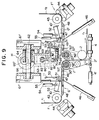
- Fig. 9 is a front view matching the view shown in Fig. 1, but taken along the line IX-IX of Fig. 12, detailing the manner in which the leading edge of a replacement web is prepared for splicing to a moving web;
- Fig. 10 is a view like Fig. 9, but showing how the leading edge of the replacement web is adhered to a splice strip;
- Fig. 11 is a view similar to Fig. 10 but showing the manner in which the splice takes place;
- Fig. 12 is a side elevation of a splice tape delivery showing the splice tape about to be withdrawn from a roll;
- Fig. 13 is a view similar to Fig. 12 but showing the splice tape about to be unspooled from the roll of tape;
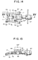
- Fig. 14 is a view partially in section taken along the line XIV-XIV in Fig. 12 and showing details of a drawing-out roller associated with the tape delivery device;
- Fig. 15 is a sectional view taken along the line XV-XV of Fig. 14; and
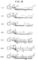
- Fig. 16 is a schematic illustration showing the step-by-step operation by which the drawing-out roller extracts a length of tape from a roll thereof.
- Before describing the apparatus of the present invention in detail, reference is made to Fig. 1 for the purpose of providing a brief overview of the apparatus. Referring to Fig. 1, reference numerals B₁, B₂ represent reel or bobbin holders having respective shafts d₁, d₂ for holding reels R₁, R₂ of a web material that is to be furnished to an automatic packaging machine (not shown). Reel R₁ on holder B₁ supplies web r₁ along a predetermined path a₁ by reason of vertical guide D and horizontal guide G to gripper roller 1' and
delivery roller 2 before web r₁ engagesrollers 3 leading to an automated packaging line (not shown). Eventually, the web spooled on reel R₁ will be depleted; and, in a conventional manner, a marker may be provided on the web near its connection with the hub d₁ of the reel for the purpose of indicating when the reel is about to be exhausted. A detector (not shown) detects this marker andactuates cutter 10 for the purpose of severing the moving web in preparation for splicing the leader edge of a replacement web to the trailing edge of the original web. Reference is made to Figs. 10 and 11 for the purpose of showing how web r₁, as drawn to the packaging equipment, travels along guide G until the trailing edge engages gripper roll 1'. - The leading edge of a replacement web partially overlies and is attached to pressure-sensitive tape n releasably held on gripper roller 1; and the gripper rollers 1, 1' move relative to each other so that, as shwon in Fig. 11, the trailing end of the moving web and tape n are sandwiched between the gripper rollers. This sandwiching action presses the moving web into engagement with adhesive on the surface of tape n thereby splicing web r₂ to web r₁ while web r₁ is moving.
- In addition to the pair of reels R₁, R₂ separately mounted for rotation on a frame, and the webs r₁, r₂ separately spooled on each reel, the apparatus of the present invention includes guides D, D' associated with the respective reels. These guides direct the respective webs along separate L-shaped paths each having legs defined by guides G, G' that terminates in gripper rollers 1, 1' whose axes are parallel to each other but perpendicular to the path of movement of webs r₁, r₂. The guides are constructed and arranged So that the leg of one path, namely guide G is aligned with the leg, namely guide G', of the other path, and the gripper rollers are adjacent each other. Because the L-shaped paths guides of the invention are identical, only the left path shown in Fig. 1 is described in detail.
- As shown in Fig. 1,
guide rollers tension lever 33 which is pivotally mounted on the frame and carriesrotatable tensions rollers tension lever 33 is a cam that engages the free end ofbrake arm 6a which is pivotally mounted on the frame and includesbrake 6 that carries a brake shoe frictionally engageable with reel R₁ mounted. In its operative position shown in Fig. 1,left tension lever 33 maintains a tension on web r₁ asbrake 6 engages the reel allowing moving web r₁ to be unspooled from this reel without looping. Whentension lever 33 is rotated to the position shown in chain lines, the brake is released freeing the reel for movement - After the marker on web r₁ is detected, as described above, and
cutter 10 operates to sever web r₁, the apparatus shown in Fig. 2 comes into operation. In such apparatus, an actuator movesdriving roller 5 into engagement with the periphery of holder B₁ for the purpose of rewinding the remnant of the web attached to the reel aftercutter 10 has severed the web. After such rewinding occurs, an actuator is operated for the purpose of movingwindback lever 7 into the position shown in Fig. 2 such that an electrically heated pad on the free end oflever 7 engages the web wound onto the hub of reel R1 thereby sealing the web remnant to itself and preventing its unwinding. The reel may now be removed from the apparatus and replaced by a fresh, full reel in preparation for its use in the manner described below. As shown in Fig. 2, driving roller 5' can be positioned to engage holder B₂ for the purpose of rewinding a web remnant onto reel R2 when that reel becomes exhausted. In a manner similar to that described above, thewindback lever 7 can be flipped to the right side as shown in Fig. 2 for the purpose of having an electrical heater engage the periphery of the web on reel R2 thus sealing the web to itself. - When reel R1 is supplying web to the packaging equipment in the manner shown in Fig. 1, reel R2 is a replacement reel carrying replacement web r₂, the free end of which will be spliced to the trailing end of web r₁ when reel R1 is depleted. Before describing in detail how the splice occurs, it is appropriate to describe how the replacement web is prepared for the splicing operation. Reference is now made to Fig. 3 which shows reel R2 carrying the replacement web mounted on holder B₂. In order to move the replacement reel onto holder B₂,
tension lever 33 is rotated to the position shown in solid lines in Fig. 1 releasing brake 6' from engagement with reel R2. - As placed on bobbin B₂, reel R2 contains replacement web r₂ spooled thereon. The free end of web r₂ has a leader attached which terminates in tip P' which projects from the web when the latter is spooled on reel R2. Associated with the leader is adhesive tape P interposed between the leader and the outer web on the reel for the purpose of releasably holding the leader to the web and preventing unspooling of the web. As a consequence of this construction, the rotation of reel R2 will cause tip P' to trace out a circular path around the center of rotation of the reel.
- Leader tip nipping mechanism C' (Fig. 3) is provided for engaging the projecting lead tip P' and removing the leader on replacement web r₂. Mechanism C' includes
arm lever 20 pivotally mounted to the frame at 21 carrying at its remote end a pair ofjaws 22 in the form of upper jaw 22' and lower jaw 22'' pivotally mounted on the arm. By operatingair cylinder 27 attached to strap 26 on which the jaws are mounted, the Jaws are tilted upwardly from the solid lines shown in Fig. 3 to the broken lines shown in that figure. As tip P' moves in a circular path about the center of rotation of reel R2, the tip eventually is engaged by upper jaw 22' as shown in Fig. 4. Actuation ofcylinder 28 closes lower jaw 22'' and captures the tip between the two jaws. Thereafter,air cylinder 27 is deactuated to the position shown in Fig. 5 as further rotation of reel R2 is terminated. The downward tilting ofjaw 22 to the position shown in Fig. 5 is accompanied by a release of the tape P and the removal of the leader from attachment to the remainder of the web on reel R2. The residual rotation of reel R2 causes web r₂ to form an open loop as shown in Fig. 5. The lower end of this loop projects downwardly toward web drawing-out mechanism E'. This mechanism includesendless belt 41 vertically arranged and mounted onrollers 42 for limited movement in opposite directions. Carried onbelt 41 is an arm that supports air cylinder 40'carrying piston rod 40. When this air cylinder is unactuated androd 40 is retracted, the bottom end of the loop shown in Fig. 5 engagesendless belt 41. When cylinder 40' is actuated,rod 40 extends outwardly (i.e., perpendicular to the paper as shown in Fig. 5) and engages the bottom of the loop. At this point, rotation ofroller 42 carries the air cylinder and rod to the position shown in Fig. 6. At the same time,cylinder 25 is actuated causingjaws 22 to move the leader attached to replacement web r₂ into engagement with the web againstanvil 23 which is pressed into engagement with the web by actuation ofair cylinder 24 as shown in Fig. 6. Thus, adhesive P engages the web which forms a closed loop as shown in Fig. 6. - In this position of the closed loop,
tension lever 33 is in the position shown in solid lines in Fig. 6 allowing continued rotation ofbelt 41 to draw web r₂ along path a₂ to the left oftension roller 34 but to the right ofguide rollers rod 40 is located adjacentsupplemental delivery roller 43, air cylinder 40' is deactuated withdrawingrod 40 from the closed loop. Meanwhile, the closed end of this loop is captured betweenroller 43 and guidebelt 44 of supplementary delivery mechanism F'. - In order to move replacement web r₂ around
roller 43,supplemental roller 45, movable roller 45', and transmission mechanism 45a are utilized. As indicated in Fig. 6, the replacement web engagesrollers belt 44. To ensure proper movement, roller 45' is moved into engagement with the web pressing the same againstroller 45 as shown in Fig. 7. By powering transmission mechanism 45a, the loop at the end of web r₂ will be drawn aroundroller 43 and ontohorizontal bottom guide 49 of guide mechanism G'. This is indicated in Fig. 7. -
Bottom guide 49 is provided with an aperture closed by hingedplate 47 the position of which is controlled byair cylinder 46. When the leading end of the closed loop is fed pastroller 43 by the operation of transmission 45a,cylinder 46 is actuated to moveplate 47 to the position shown in Fig. 7 allowing the closed loop to be diverted fromguide 49 as the replacement web is unspooled from reel R2. Eventually, the leader is fed pastroller 43 to the position shown in Fig. 8 whereupon actuation ofair cylinder 54 movesarm 52 clockwise as shown in Figs. 7 and 8 allowing cutter 10' to sever web r₂ as cutter 10' entersrecess 48 inbottom guide 49. In this manner, the closed loop at the free end of web r₂ is detached from the web thereby establishing a leading edge on replacement web r₂ as shown in Fig. 8. As described in below, continued operation of transmission mechanism 45a will move the leading edge of replacement web r₂ toward gripper roller 1 at the free end ofguide 49. Before the free end reaches this gripper roller, however, adhesive tape delivery system H, in the manner described below, is effective to place a tape strip n on roller 1 as shown in Fig. 10. This strip is as long as web r₂ and the operation of transmission mechanism 45a is such that, in conjunction with the application of a jet of air through aperture 50' the free edge of replacement web r₂ is positioned approximately half-way across the width of tape n and in engagement with adhesive covering the upper surface of this tape. This is illustrated in Figs. 9 and 10; and upon actuation ofcylinder 55, pressure finger 11' is moved from the position shown in solid lines in Fig. 10 to the position shown in chain lines in this figure into engagement with the replacement web thus causing the free end of the replacement web to be adhered to the pressure-sensitive tape. The apparatus described in connection with Figs. 9 and 10 is then terminated while the apparatus continues to feed the moving tape from reel R1 to the packaging equipment. Further action to carry out the splicing operation follows upon detection of a marker on the moving web in the manner described above. This operation will be described in detail after an explanation is given of the manner in which tape n is positioned on gripper roller 1. - As shown in Fig. 12,
main frame 61 of the apparatus is provided with a pair of spaced sidewalls 61' (see Fig. 9) projecting in a direction perpendicular to the direction of movement of the webs on bottom guides 48 and 49. A pair ofguide rods 62 are mounted between sidewalls 61' for supportinghub portions 64 carryingflange 63 to which guide 70 is attached.Guide 70 guidesU-shaped frame 68 provided with slot 69' that fits slidingly aroundguide 70.Frame 68 is rigidly connected to rod 67' associated withair cylinder 67. When this cylinder is in its unactuated state,frame 68 occupies the position shown in Fig. 12; and whencylinder 67 is actuated,frame 68 is extended to the position shown in Fig. 13. - Rigidly attached to
flange 63 and extending in a direction perpendicular to the direction of rod 67' israck 66 engaged with pinion 65' attached tomotor shaft 65 carried by motor M which is rigidly connected to frame 61. The axis of motor M is parallel to the axis ofactuator 67 with the result that selective rotation of this motor will moveflange 63 in the same direction that the webs move onguides frame 68 may be positioned over either gripper roller 1 as shown in Fig. 9, or over gripper roller 1'. - When web r₁ is the moving web and is being furnished to the packaging equipment, motor M is energized to move
frame 63 to the position shown in Fig. 9 whereframe 68 is positioned above gripper roller 1. In this position, pressure-sensitive tape delivery system H is positioned so that tape n from reel N mounted on guide 60 (Fig. 13) can be unspooled onto gripper roller 1. Tape n comprises a substrate bearing an adhesive on its upper surface. Thus, as shown in Fig. 12, the tape may be threaded manually betweenfeed rollers 90, 90' and into engagement with atable carrying groove 92 connected tosuction line 91. Thus, an operator may manually position tape n as shown in Fig. 12, the tape being held in this position with the free end, reaching to groove 86 in gripper roller 1, by the suction applied to groove 92.Frame 68 is provided with drawing-out roller h₁ for the purpose of engaging the adhesive surface on tape n, drawing the tape to the right as shown in Fig. 12 across gripper roll 1 as shown by the chain lines in this figure. This operation is illustrated schematically in Fig. 16 to which reference should be made in connection with the discussion of Figs. 12 and 13. - Drawing-out roller h₁ has axial ends 73 (Fig. 14) which are rotatably mounted in
arms 71, 71' which themselves are pivoted at 72 to frame 68.Leaf spring 78 attached to frame 68 and passing aroundpivot pin 72 engages a pin adjacent roller h₁ and biases this roller in a counterclockwise direction as seen in Figs. 12, 13 and 15. - Rigidly attached to
shaft 73 isratchet wheel 75 such that both roller h₁ and ratchetwheel 75 turn together. Engaged withratchet wheel 75 is tip 76' ofpawl 76 which is pivotally mounted on an extension to pin 72 as shown in Fig. 14. On the end ofpawl 76 opposite tip 76' iscam roller 77 which is engageable with cam surface 82' oncam 82 rigidly connected toflange 63. The position ofcam surface 82 with respect tocam follower 77 is such that whenfollower 77 is engaged with surface 82',pawl 76 is rotated such that tip 76' is out of engagement withratchet wheel 75. Thus, roller h₁ is free to rotate in both directions in this position offrame 68. On the other hand, when the frame is moved by the actuation ofair cylinder 67 untilcam follower 77 disengages cam 82', tip 76' engagesratchet wheel 76 and prevents rotation of roller h₁ in a clockwise direction as viewed in Figs. 12 and 13. However, the ratchet and pawl connection is such as to permit counterclockwise rotation of the roller. -
Arm 71, which provides a rotational mounting forpin 73, at one end of the arm, has an extension at the opposite end on whichcam follower 74 is rotatably mounted. This cam follower is aligned withmovable cam 81 that is suspended fromflange 63 to one side thereof by bell crank 80 and link 80'. This mounting permitscam 81 to move both axially in the direction offlange 63 and transversely to this direction as shown in Fig. 13. That is to say, whenair cylinder 83 having rod 83' attached thereto is actuated, bell crank 80 occupies the position shown in Fig. 13 andcam 81 is physically raised out of the path of engagement withcam follower 74. Whenair cylinder 83 is deactuated, bell crank 80 is pivoted clockwise as shown in Fig. 13 to the position shown in Fig. 12 thereby movingcam 81 from the position shown in solid lines in Fig. 13 to the chain lines shown in this figure. In the latter position ofcam 81,cam follower 74 is engageable withcam 81 asframe 68 is moved thereby causingarm 71 to rotate aboutpivot 72 thus raising roller h₁ against the action ofspring 78. - Before describing how roller h₁ is used to withdraw a strip of tape from reel N across gripper roller 1, the construction of this roller is described. As shown in Fig. 12, roller 1 comprises
shaft 58 rotatably mounted onsupport frame 56, 56', the axis of this shaft being perpendicular to the direction of movement of the replacement tape and of the moving tape, and parallel to the direction in which tape n is withdrawn from reel N. Attached toshaft 58 is a hollow cylinder carrying on its periphery an outer cylinder that includes apertures 57' connected to the interior of the hollow sleeve and forming what is termedsuction surface 57 on the periphery of roller 1. Suction passage 58' connects suction holes 57' to a vacuum source which selectively applies a vacuum for the purpose of releasably holding tape n to roller 1 when the tape is drawn acrosssurface 57 by roller h₁. - In operation, the various components of adhesive tape delivery system H occupy the position shown in Fig. 12 after tape n has been manually positioned as shown in this figure. Roller h₁ is located above
surface 57 as indicated in Fig. 16(i), this position of roller h₁ being established becausecam follower 74 is engaged with cam surface 81'. Actuation ofcylinder 67moves frame 68 to the left as shown in Fig. 12, roller h₁ remaining spaced above the level ofsurface 57 as shown in Fig. 16(ii) becausecam follower 74 remains engaged with cam surface 81'. Further movement of rod 67'causes cam follower 74 to unseat from surface 81' allowing roller h₁ to pivot counterclockwise as seen in Fig. 15 until the roller engages the adhesive surface on tape n as shown in Fig. 16(iii). The tacky nature of the upper surface of tape n causes the tape to adhere to roller h₁ under the resilient pressure effected byspring 78. At this point in the displacement offrame 68,cam follower 77 is disengaged from cam surface 82' with the result that pawl 76 engagesratchet wheel 75 which prevents clockwise rotation of roller h₁ as seen in Fig. 13 but permits counterclockwise rotation. As a consequence, further movement of rod 67' asair cylinder 67 is continued to be actuated, causes roller h₁ to rotate as rod 67' moves thereby rolling tape n around roller h₁ as indicated in Fig. 16(iv). Thus, the free end of tape n is securely attached to roller h₁; and, deactuation ofcylinder 67causes frame 68 to return to the right as seen in Fig. 13 drawing tape from roll N acrosssurface 57. At this point in time, suction is applied to the surface and tape n is releasably held on the surface as roller h₁ moves to the right as shown in Fig. 16(v). The tape is withdrawn from reel N because the free end of the tape is wrapped around roller h₁ and the ratchet wheel prevents revisable rotation of the roller. - Just before roller h₁ reaches its rightmost terminal position as shown in Fig. 13,
cam follower 77 onpawl 76 engages cam surface 82' thus pivoting the tip 76' of the pawl out of engagement withratchet wheel 75 freeing roller h₁ for rotational movement. This occurs as rod 67' is withdrawn further intoair cylinder 67 unwinding the free end of the tape end from the roller as the suction on roller 1 maintains the tape onsuction surface 57. When the roller returns to its rightmost position, actuation ofcylinder 83 causes bell crank 80 to pivot thereby moving cam surface 81' into engagement withcam follower 74 pivoting roller h₁ clockwise aboutpivot 72 and raising the roller above the surface of roller 1 as shown in Fig. 16(vii). Strip n has thus been positioned transversely to the direction of movement of the replacement web and its path as shown in Fig. 9. At this point,air cylinder 84 is actuated moving rod 84' downwardly as shown in Fig. 13 and causing blade h₂ to engage and sever from roll n the portion of the strip n lying on roller 1 as shown in Fig. 16(vi).Groove 86 provides clearance for blade h₂. - At this point, transmission 45a may be operated for the purpose of moving the leading edge of replacement web r₂ into engagement with strip n lying on roller 1. To facilitate this, an air jet may be applied to aperture 50' enabling the leading edge of the replacement web to overlie the strip on roller 1. As shown in Fig. 9, the leading edge of the replacement web covers about half the width of strip n. The other half of the width of strip n is uncovered exposing the adhesive on the strip. At this point,
cylinder 55 is actuated causing finger 11' to engage the leading edge of the replacement web and press the same into tight contact with strip n thus adhering the leading edge to the strip. - Eventually, reel R₁ will be depleted and
cutter 10 will be actuated to engage moving web r₁ establishing its trailing edge as described above. The trailing edge will continue to move until it reaches roller 1'. At this point, roller 1' is rotated clockwise and roller 1' is rotated counter-clockwise as seen in Fig. 11, andcylinder 4 is actuated thus pivoting roller 1' toward roller 1. The pivotal movement of roller 1 as suction is applied to parts 57', draws tape n toward web r₁ as the latter moves around roller 1'. The trailing end of web r₁ is thus pressed into engagement with the exposed adhesive on the half of tape n that is not covered by the leading end of replacement web r₂. Web r₂ is thus connected to web r₁ and is drawn therealong by the mechanism that pulls web r₁. To ensure proper contact between web r₁ and the adhesive on tape n, cylinder 4' is actuated to move roller 2' into engagement withroller 2 as the splice joint posses betweenrollers 2 and 2'. - Rollers 1 and 1' are thereafter returned to the positions shown in Fig. 10, and suction is applied to roller 1' in preparation for it to receive a strip of tape. In addition, motor M is actuated to move tape roll n from alignment with roller 1 into alignment with roller 1'. The process described above for withdrawing a strip of tape from roll n is then repeated, but the tape is laid out on roller 1 in preparation for receiving the leading edge of a new web on a new reel that replaces the axhausted reel on bobbin holder B1.
Claims (8)
- Apparatus for splicing a replacement web (r₂) to a moving web, comprising:a) guide means (G) for guiding said moving web (r₁) along a predetermined path (a₁);b) cutter means (10') for severing a portion of said replacement web (r₂) to establish the leading edge thereof;c) a splicing station (N) positioned in said path (a₁) for splicing said leading edge to said moving web (r₂) while the latter is moving; andd) a replacement reel (R₂) on which said replacement web (r₂) is spooled for storing said replacement web (r₂) which has a free end to which a leader (P) is attached; characterised in that said leader (P) has pressure-sensitive adhesive for releasably engaging the web (r₂) to prevent unspooling thereof and terminating in a tip (P') that projects from the web (r₂) when the layer is basically engaged with the web (r₂); and characterised by(i) a leader tip nipping mechanism (C') for selectively gripping said leader (P) and unspooling a length of replacement web (r₂) from said replacement reel (R₂) into a closed loop;(ii) a web drawing out mechanism (E) cooperable with said loop for capturing said replacement web (r₁) upstream of said loop; and(iii) a supply delivery mechanism (F') for unspooling said web (r₂) from said reel (R₂) and severing said web (r₂) downstream of its capture for separating said loop from the remainder of said replacement web (r₂) and forming the leading edge thereof.
- Apparatus according to claim 1, characterised in that said leader tip nipping mechanism (C') includes means for rotating said reel (R₂); a movable arm (22) having actuable jaws (22; 22''); means (22) for moving said arm (22) until said jaws (22, 22'') are positioned to intercept said tip (P) as the reel (R₂) is rotated; and means (28) for actuating said jaws (22, 22'') after said tip (P') is intercepted for capturing said tip (P') in said jaws (22', 22'').
- Apparatus according to claim 2, characterised by means (25) for moving said arm (22) after said tip (P') is captured to form an open loop, until the adhesive on said leader (P) is engaged with the replacement web (r₂) thus forming a closed loop.
- Apparatus according to claim 3, characterised in that said web drawing out mechanism includes a rod (40) mounted for longitudinal movement along the axis of the rod (40) which is transverse to the direction in which the replacement web (r₂) is unspooled from said reel (R₂); means for longitudinally axially moving the rod (40) into the closed loop; and means (41, 42) for moving the rod (40) in a direction parallel to the direction in which the replacement web (r₂) is unspooled from the reel; and means for withdrawing said rod (40) from said loop.
- Apparatus according to claim 4, characterised in that said supplementary delivery mechanism (F') includes means (45, 45') for capturing said loop before the rod (40) is withdrawn; and means (43, 44) for unspooling the web from the reel, said cutter means (10') being a part of said supply delivery mechanism (F').
- Apparatus for splicing a replacement web (r₂) to a moving web (r₁) characterised bya) a reel (R₂) mounted on a frame;b) a web (r₂) spooled on said reel (R₁) and having a free end;c) a leader (P) attached to the free end of said web (r₂);d) pressure-sensitive adhesive means on the leader (P) for releasably attaching said leader (P) to said web (r₂) to prevent unspooling of the web (r₂) on the reel (R₂);e) a leader tip nipping mechanism (C') mounted on said frame and having a movable arm (22) on which actuable jaws (22', 22'') are mounted;f) means (27) for moving said arm (22) to a position on which said jaws (22', 22'') intercept said leader (P) when said reel (R₂) is rotated;g) means (28) for actuating said jaws (22', 22'') to grip said leader (P) when it is intercepted by said jaw (22', 22'');h) means for unspooling said web (r₂) from said reel (R₂) after the leader (P) is gripped by said jaws (22', 22'') to form an open loop; andi) means (25) for moving said arm (22) to a position at which the adhesive means on said leader (P) is squeezed between the leader (P) and the web (r₂) to form a closed loop.
- Apparatus according to claim 6, characterised by a drawing out mechanism comprising:a) a rod (40) mounted for movement in a direction parallel to the axis of the reel;b) an actuator for selectively moving said rod (40) into said closed loop;c) means for moving said actuator and rod away from said reel (r₂) thereby unspool the web (r₂) therefrom;d) a supplementary delviery system (F') engageable by said closed loop for delivering the same to a guide mechanism (G').e) a cutter (10') selectively operable to sever said web (r₂) upstream of said closed loop to establish the leading edge of said web; andf) said supplementary delivery system (F') being constructed and arranged to engage said web (r₂) to move the leading edge on said guide mechanism (G').
- Apparatus according to claim 7, characterised by a tape delivery system (H') effective to position the leading edge of said web (r₂) on a tape (n) oriented transversely to the direction of movement of said web (r₂) in said guide mechanism (G') said web (r₂) covering about one half of the width of the tape (n) which has pressure-sensitive adhesive on one surface thereof in contact with said web (r₂).
Applications Claiming Priority (3)
| Application Number | Priority Date | Filing Date | Title |
|---|---|---|---|
| JP312564/86 | 1986-12-25 | ||
| JP61312564A JPS63162434A (en) | 1986-12-25 | 1986-12-25 | Exchanger for packaging material in packaging-material delivery device |
| EP87118499A EP0273287B1 (en) | 1986-12-25 | 1987-12-14 | Apparatus for splicing a replacement web to a moving web |
Related Parent Applications (1)
| Application Number | Title | Priority Date | Filing Date |
|---|---|---|---|
| EP87118499.0 Division | 1987-12-14 |
Publications (2)
| Publication Number | Publication Date |
|---|---|
| EP0521532A1 true EP0521532A1 (en) | 1993-01-07 |
| EP0521532B1 EP0521532B1 (en) | 1995-08-02 |
Family
ID=18030729
Family Applications (3)
| Application Number | Title | Priority Date | Filing Date |
|---|---|---|---|
| EP87118499A Expired - Lifetime EP0273287B1 (en) | 1986-12-25 | 1987-12-14 | Apparatus for splicing a replacement web to a moving web |
| EP92114262A Expired - Lifetime EP0521532B1 (en) | 1986-12-25 | 1987-12-14 | Apparatus for splicing a replacement web to a moving web |
| EP92114263A Expired - Lifetime EP0521533B1 (en) | 1986-12-25 | 1987-12-14 | Apparatus for splicing a replacement web to a moving web |
Family Applications Before (1)
| Application Number | Title | Priority Date | Filing Date |
|---|---|---|---|
| EP87118499A Expired - Lifetime EP0273287B1 (en) | 1986-12-25 | 1987-12-14 | Apparatus for splicing a replacement web to a moving web |
Family Applications After (1)
| Application Number | Title | Priority Date | Filing Date |
|---|---|---|---|
| EP92114263A Expired - Lifetime EP0521533B1 (en) | 1986-12-25 | 1987-12-14 | Apparatus for splicing a replacement web to a moving web |
Country Status (4)
| Country | Link |
|---|---|
| US (1) | US4848691A (en) |
| EP (3) | EP0273287B1 (en) |
| JP (1) | JPS63162434A (en) |
| DE (3) | DE3786905T2 (en) |
Cited By (5)
| Publication number | Priority date | Publication date | Assignee | Title |
|---|---|---|---|---|
| DE4314552A1 (en) * | 1993-05-04 | 1994-11-10 | Pactec Dresden Gmbh | Device for connecting webs of packaging material |
| EP0680910A1 (en) * | 1994-05-04 | 1995-11-08 | Heinrich Vorwald GmbH & Co. KG | Method and device for splicing webs of material |
| EP1340702A1 (en) * | 1998-02-06 | 2003-09-03 | Focke & Co. (GmbH & Co.) | Device for drawing off a material web |
| WO2005016805A1 (en) * | 2003-07-25 | 2005-02-24 | Kimberly-Clark Worldwide, Inc. | Rotary heat sealing device and method |
| EP1632448A1 (en) * | 2004-09-07 | 2006-03-08 | Alcan Technology & Management Ltd. | Method for splicing the beginning of a web with the end of said web |
Families Citing this family (36)
| Publication number | Priority date | Publication date | Assignee | Title |
|---|---|---|---|---|
| US4984750A (en) * | 1988-07-01 | 1991-01-15 | Tokyo Automatic Machinery Works Ltd. | Method and apparatus for replacing web-like material in a web-like material supplying device |
| JPH089441B2 (en) * | 1989-04-26 | 1996-01-31 | 日本たばこ産業株式会社 | Continuous feeder for strips |
| JP2506441B2 (en) * | 1989-04-26 | 1996-06-12 | 日本たばこ産業株式会社 | Belt-shaped connecting device |
| US5238522A (en) * | 1989-04-26 | 1993-08-24 | Japan Tobacco Inc. | Joining device for strip-like material |
| JPH089438B2 (en) * | 1989-04-26 | 1996-01-31 | 日本たばこ産業株式会社 | Cutting device for feeding out the leading edge of the band-shaped material fed from the winding roll |
| DE3931852A1 (en) * | 1989-09-23 | 1991-04-04 | Erhardt & Leimer Gmbh | ROLE CHANGER |
| US5066345A (en) * | 1990-01-26 | 1991-11-19 | Eastman Kodak Company | Apparatus and method for splicing webs of indeterminate length |
| US5066346A (en) * | 1990-01-26 | 1991-11-19 | Eastman Kodak Company | Apparatus and method for splicing webs of indeterminate length |
| US5053096A (en) * | 1990-01-26 | 1991-10-01 | Eastman Kodak Company | Apparatus and method for splicing webs of indeterminate length |
| JP2844117B2 (en) * | 1990-08-24 | 1999-01-06 | 四国化工機株式会社 | Continuous rewinding device for multiple rolled tapes |
| GB9022404D0 (en) * | 1990-10-16 | 1990-11-28 | Molins Plc | Web conveying apparatus |
| DE4107254C2 (en) * | 1991-03-07 | 2000-02-10 | Focke & Co | Device for connecting material webs |
| EP0539985B1 (en) * | 1991-10-31 | 1996-03-20 | Japan Tobacco Inc. | Device for connecting web end portions |
| US5256232A (en) * | 1992-07-27 | 1993-10-26 | Eastman Kodak Company | Apparatus and method for winding strips of web material onto spools |
| DE69403657T2 (en) * | 1993-05-26 | 1998-01-22 | Minnesota Mining & Mfg | ADHESIVE TAPE FEEDING AND APPLICATION SYSTEM WITH A TRAIN CONNECTING MECHANISM |
| IT1263427B (en) * | 1993-06-01 | 1996-08-05 | Gd Spa | DEVICE FOR THE AUTOMATIC JOINT OF TAPES OF SMALL TRANSVERSAL DIMENSIONS. |
| US5624526A (en) * | 1994-10-17 | 1997-04-29 | Minnesota Mining And Manufacturing | Continuous tape supply system including a tape splicing mechanism for use with box taping machines |
| JP3690830B2 (en) * | 1995-02-14 | 2005-08-31 | 株式会社東京自働機械製作所 | Opening tape changer |
| DE10012000A1 (en) * | 2000-03-11 | 2001-09-13 | Winkler & Duennebier Ag | Reel changer for a device for manufacturing hygiene products |
| US6481664B1 (en) * | 2000-10-02 | 2002-11-19 | Dynamex Corporation | Automatic tape crossover |
| JP4025292B2 (en) | 2001-10-16 | 2007-12-19 | 日本たばこ産業株式会社 | Adhesive tape for connecting webs used as packaging material for rod-shaped articles to each other, and apparatus for supplying the adhesive tape |
| JP4170181B2 (en) | 2003-09-09 | 2008-10-22 | リンテック株式会社 | Belt-like body connection device and connection method |
| ITFI20040108A1 (en) * | 2004-05-07 | 2004-08-07 | Perini Fabio Spa | MULTIFORM UNWINDING DEVICE |
| WO2005110902A1 (en) * | 2004-05-14 | 2005-11-24 | Impresstik Machinery Pty Ltd | Feeding webs for processing and removing webs |
| WO2007046137A1 (en) * | 2005-10-19 | 2007-04-26 | Orihiro Engineering Co., Ltd. | Packaging device |
| US20090308614A1 (en) * | 2008-06-11 | 2009-12-17 | Sanchez James S | Coated extrudable ball seats |
| EP2440466A4 (en) * | 2009-06-09 | 2015-12-09 | Graphic Packaging Int Inc | Article selection and placement assembly and method |
| US8668018B2 (en) | 2011-03-10 | 2014-03-11 | Baker Hughes Incorporated | Selective dart system for actuating downhole tools and methods of using same |
| US8668006B2 (en) | 2011-04-13 | 2014-03-11 | Baker Hughes Incorporated | Ball seat having ball support member |
| US8479808B2 (en) | 2011-06-01 | 2013-07-09 | Baker Hughes Incorporated | Downhole tools having radially expandable seat member |
| US9145758B2 (en) | 2011-06-09 | 2015-09-29 | Baker Hughes Incorporated | Sleeved ball seat |
| US9004091B2 (en) | 2011-12-08 | 2015-04-14 | Baker Hughes Incorporated | Shape-memory apparatuses for restricting fluid flow through a conduit and methods of using same |
| US9016388B2 (en) | 2012-02-03 | 2015-04-28 | Baker Hughes Incorporated | Wiper plug elements and methods of stimulating a wellbore environment |
| CN104803041B (en) * | 2015-03-11 | 2016-11-30 | 重庆市巴南区前进机械厂 | A kind of food package using electromagnetic actuator device and using method thereof |
| US10279608B2 (en) * | 2016-09-28 | 2019-05-07 | Océ Holding B.V. | Method for loading a web; apparatus for handling a web |
| CN113460748B (en) * | 2021-07-05 | 2023-03-07 | 江苏电子信息职业学院 | Automatic change winder |
Citations (4)
| Publication number | Priority date | Publication date | Assignee | Title |
|---|---|---|---|---|
| DE3538893A1 (en) * | 1984-11-22 | 1986-05-22 | Hauni-Werke Körber & Co KG, 2050 Hamburg | Reel-changing apparatus |
| EP0189761A2 (en) * | 1985-01-28 | 1986-08-06 | Japan Tobacco Inc. | Device for automatically stripping and delivering fore end of a paper roll |
| GB2174371A (en) * | 1985-04-27 | 1986-11-05 | Bat Cigarettenfab Gmbh | Splicing and threading device for strips of paper, especially for strips of cigarette paper |
| EP0349350A2 (en) * | 1988-07-01 | 1990-01-03 | Tokyo Automatic Machinery Works Limited | Method and apparatus for replacing web-like material in a web-like material supplying device |
Family Cites Families (12)
| Publication number | Priority date | Publication date | Assignee | Title |
|---|---|---|---|---|
| DE4225C (en) * | J. C. LYON & D. S. BROWN in New-York (V. St. v. A.) | Resilient holder to prevent tape and the like from unwinding from the roll | ||
| US3075718A (en) * | 1960-09-28 | 1963-01-29 | Jr Richard A Butler | Web splicing machine |
| US3089661A (en) * | 1961-06-14 | 1963-05-14 | American Mach & Foundry | Automatic cigarette paper splicer |
| GB1328485A (en) * | 1971-01-27 | 1973-08-30 | Ilford Ltd | Web splicing apparatus |
| JPS5329174B2 (en) * | 1973-11-29 | 1978-08-18 | ||
| JPS5125670U (en) * | 1974-08-15 | 1976-02-25 | ||
| GB2093808B (en) * | 1980-12-22 | 1985-05-30 | British American Tobacco Co | Splicing webs |
| DE3130631A1 (en) * | 1981-08-01 | 1983-02-17 | Blume & Redecker GmbH, 3000 Hannover | Process and device for attaching the start and the end of a film wound on a plastic reel core and a reel produced therewith |
| US4450039A (en) * | 1982-08-23 | 1984-05-22 | Harris Graphics Corporation | Web splicing apparatus |
| IT1169165B (en) * | 1983-02-15 | 1987-05-27 | Gd Spa | METHOD FOR THE REPLACEMENT OF A FIRST SPOOL OF TAPE MATERIAL IN EXHAUST WITH THE SECOND NEW SPOOL |
| IT1195394B (en) * | 1983-05-03 | 1988-10-19 | Azionaria Costruzioni Acma Spa | EQUIPMENT TO MAKE THE JUNCTION BETWEEN THE TERMINAL END OF A LOW REEL AND THE INITIAL ONE OF A NEW REEL |
| FR2572373B1 (en) * | 1984-10-25 | 1987-05-15 | Alaimo Andre | DEVICE FOR CONDUCTING CONTINUOUS STRIPS BY ENSURING THEIR SOLIDARIZATION ONE BY ONE AFTER THE OTHERS |
-
1986
- 1986-12-25 JP JP61312564A patent/JPS63162434A/en active Granted
-
1987
- 1987-12-14 EP EP87118499A patent/EP0273287B1/en not_active Expired - Lifetime
- 1987-12-14 EP EP92114262A patent/EP0521532B1/en not_active Expired - Lifetime
- 1987-12-14 DE DE87118499T patent/DE3786905T2/en not_active Expired - Fee Related
- 1987-12-14 DE DE3751729T patent/DE3751729T2/en not_active Expired - Fee Related
- 1987-12-14 EP EP92114263A patent/EP0521533B1/en not_active Expired - Lifetime
- 1987-12-14 DE DE3751440T patent/DE3751440T2/en not_active Expired - Fee Related
- 1987-12-15 US US07/133,350 patent/US4848691A/en not_active Expired - Lifetime
Patent Citations (4)
| Publication number | Priority date | Publication date | Assignee | Title |
|---|---|---|---|---|
| DE3538893A1 (en) * | 1984-11-22 | 1986-05-22 | Hauni-Werke Körber & Co KG, 2050 Hamburg | Reel-changing apparatus |
| EP0189761A2 (en) * | 1985-01-28 | 1986-08-06 | Japan Tobacco Inc. | Device for automatically stripping and delivering fore end of a paper roll |
| GB2174371A (en) * | 1985-04-27 | 1986-11-05 | Bat Cigarettenfab Gmbh | Splicing and threading device for strips of paper, especially for strips of cigarette paper |
| EP0349350A2 (en) * | 1988-07-01 | 1990-01-03 | Tokyo Automatic Machinery Works Limited | Method and apparatus for replacing web-like material in a web-like material supplying device |
Cited By (7)
| Publication number | Priority date | Publication date | Assignee | Title |
|---|---|---|---|---|
| DE4314552A1 (en) * | 1993-05-04 | 1994-11-10 | Pactec Dresden Gmbh | Device for connecting webs of packaging material |
| EP0680910A1 (en) * | 1994-05-04 | 1995-11-08 | Heinrich Vorwald GmbH & Co. KG | Method and device for splicing webs of material |
| EP1340702A1 (en) * | 1998-02-06 | 2003-09-03 | Focke & Co. (GmbH & Co.) | Device for drawing off a material web |
| WO2005016805A1 (en) * | 2003-07-25 | 2005-02-24 | Kimberly-Clark Worldwide, Inc. | Rotary heat sealing device and method |
| US7182827B2 (en) | 2003-07-25 | 2007-02-27 | Kimberly-Clark Worldwide, Inc. | Rotary heat sealing device and method |
| EP1632448A1 (en) * | 2004-09-07 | 2006-03-08 | Alcan Technology & Management Ltd. | Method for splicing the beginning of a web with the end of said web |
| WO2006027154A1 (en) * | 2004-09-07 | 2006-03-16 | Alcan Technology & Management Ltd. | Method for joining the end of a web to the beginning of another web |
Also Published As
| Publication number | Publication date |
|---|---|
| EP0273287B1 (en) | 1993-08-04 |
| DE3751440D1 (en) | 1995-09-07 |
| JPH0479893B2 (en) | 1992-12-17 |
| DE3751729T2 (en) | 1996-07-25 |
| DE3786905T2 (en) | 1993-11-11 |
| JPS63162434A (en) | 1988-07-06 |
| DE3751440T2 (en) | 1996-01-04 |
| US4848691A (en) | 1989-07-18 |
| EP0521533B1 (en) | 1996-03-06 |
| EP0273287A2 (en) | 1988-07-06 |
| EP0273287A3 (en) | 1990-08-01 |
| DE3786905D1 (en) | 1993-09-09 |
| DE3751729D1 (en) | 1996-04-11 |
| EP0521532B1 (en) | 1995-08-02 |
| EP0521533A1 (en) | 1993-01-07 |
Similar Documents
| Publication | Publication Date | Title |
|---|---|---|
| EP0521532B1 (en) | Apparatus for splicing a replacement web to a moving web | |
| EP0129237B1 (en) | Automatic adhesive double coated tape applying device | |
| JP4202382B2 (en) | Device for gripping material web | |
| CA1319356C (en) | Unwinding apparatus for paper or board web rolls or the like | |
| JP3406426B2 (en) | Adhesive tape supply device | |
| US6792987B2 (en) | Automatic label splicing apparatus | |
| US4579293A (en) | Apparatus for withdrawing the leaders of webs from reels of convoluted flexible material | |
| JPH07144800A (en) | Method and device for connecting material web, especially packing material web | |
| CA2468805A1 (en) | Method and apparatus for applying a splicing tape to a roll of sheet material | |
| US4892263A (en) | Unwinding apparatus for a paper or board web | |
| JPH04201825A (en) | Automatic connecting device for successive package | |
| JPH05123152A (en) | Automatically exchanging device for web reel | |
| US4749139A (en) | Apparatus for severing a web | |
| GB1216310A (en) | Reel change and splicing device in apparatus for feeding strip material to machines | |
| JP3666325B2 (en) | Method and apparatus for supplying wound sheet for wire harness | |
| EP0539986B1 (en) | Apparatus for drawing out a web end from a web roll | |
| JP2000118809A (en) | Device to transfer both side adhesive type connecting material | |
| US4911028A (en) | Apparatus and method for carrying out measurements on a bobbin of sheet material | |
| JPH0613168Y2 (en) | Strip material exchange device in strip material supply device | |
| JPS6366052A (en) | Paper splicing device | |
| JPH05123148A (en) | Device for cutting tip of bonded web | |
| JPH05123146A (en) | Device for feeding adhesive tape for web | |
| JP2001278513A (en) | Device and method for splicing long material | |
| JPH1045289A (en) | Paper feeding device of rotary printer | |
| JPH1095408A (en) | Connecting device for belt-shaped material |
Legal Events
| Date | Code | Title | Description |
|---|---|---|---|
| PUAI | Public reference made under article 153(3) epc to a published international application that has entered the european phase |
Free format text: ORIGINAL CODE: 0009012 |
|
| AC | Divisional application: reference to earlier application |
Ref document number: 273287 Country of ref document: EP |
|
| AK | Designated contracting states |
Kind code of ref document: A1 Designated state(s): DE GB IT |
|
| 17P | Request for examination filed |
Effective date: 19930309 |
|
| 17Q | First examination report despatched |
Effective date: 19940530 |
|
| GRAA | (expected) grant |
Free format text: ORIGINAL CODE: 0009210 |
|
| ITF | It: translation for a ep patent filed |
Owner name: ING. FERRAROTTI GIOVANNI |
|
| AC | Divisional application: reference to earlier application |
Ref document number: 273287 Country of ref document: EP |
|
| AK | Designated contracting states |
Kind code of ref document: B1 Designated state(s): DE GB IT |
|
| REF | Corresponds to: |
Ref document number: 3751440 Country of ref document: DE Date of ref document: 19950907 |
|
| PLBE | No opposition filed within time limit |
Free format text: ORIGINAL CODE: 0009261 |
|
| STAA | Information on the status of an ep patent application or granted ep patent |
Free format text: STATUS: NO OPPOSITION FILED WITHIN TIME LIMIT |
|
| 26N | No opposition filed | ||
| REG | Reference to a national code |
Ref country code: GB Ref legal event code: 732E |
|
| REG | Reference to a national code |
Ref country code: GB Ref legal event code: IF02 |
|
| PGFP | Annual fee paid to national office [announced via postgrant information from national office to epo] |
Ref country code: GB Payment date: 20031210 Year of fee payment: 17 |
|
| PGFP | Annual fee paid to national office [announced via postgrant information from national office to epo] |
Ref country code: DE Payment date: 20031229 Year of fee payment: 17 |
|
| PG25 | Lapsed in a contracting state [announced via postgrant information from national office to epo] |
Ref country code: GB Free format text: LAPSE BECAUSE OF NON-PAYMENT OF DUE FEES Effective date: 20041214 |
|
| PG25 | Lapsed in a contracting state [announced via postgrant information from national office to epo] |
Ref country code: DE Free format text: LAPSE BECAUSE OF NON-PAYMENT OF DUE FEES Effective date: 20050701 |
|
| GBPC | Gb: european patent ceased through non-payment of renewal fee |
Effective date: 20041214 |
|
| PG25 | Lapsed in a contracting state [announced via postgrant information from national office to epo] |
Ref country code: IT Free format text: LAPSE BECAUSE OF NON-PAYMENT OF DUE FEES;WARNING: LAPSES OF ITALIAN PATENTS WITH EFFECTIVE DATE BEFORE 2007 MAY HAVE OCCURRED AT ANY TIME BEFORE 2007. THE CORRECT EFFECTIVE DATE MAY BE DIFFERENT FROM THE ONE RECORDED. Effective date: 20051214 |