EP0525478A2 - Liquid crystal display cell - Google Patents
Liquid crystal display cell Download PDFInfo
- Publication number
- EP0525478A2 EP0525478A2 EP92111775A EP92111775A EP0525478A2 EP 0525478 A2 EP0525478 A2 EP 0525478A2 EP 92111775 A EP92111775 A EP 92111775A EP 92111775 A EP92111775 A EP 92111775A EP 0525478 A2 EP0525478 A2 EP 0525478A2
- Authority
- EP
- European Patent Office
- Prior art keywords
- liquid crystal
- orientation
- crystal display
- plates
- display cell
- Prior art date
- Legal status (The legal status is an assumption and is not a legal conclusion. Google has not performed a legal analysis and makes no representation as to the accuracy of the status listed.)
- Granted
Links
Images

Classifications
-
- G—PHYSICS
- G02—OPTICS
- G02F—OPTICAL DEVICES OR ARRANGEMENTS FOR THE CONTROL OF LIGHT BY MODIFICATION OF THE OPTICAL PROPERTIES OF THE MEDIA OF THE ELEMENTS INVOLVED THEREIN; NON-LINEAR OPTICS; FREQUENCY-CHANGING OF LIGHT; OPTICAL LOGIC ELEMENTS; OPTICAL ANALOGUE/DIGITAL CONVERTERS
- G02F1/00—Devices or arrangements for the control of the intensity, colour, phase, polarisation or direction of light arriving from an independent light source, e.g. switching, gating or modulating; Non-linear optics
- G02F1/01—Devices or arrangements for the control of the intensity, colour, phase, polarisation or direction of light arriving from an independent light source, e.g. switching, gating or modulating; Non-linear optics for the control of the intensity, phase, polarisation or colour
- G02F1/13—Devices or arrangements for the control of the intensity, colour, phase, polarisation or direction of light arriving from an independent light source, e.g. switching, gating or modulating; Non-linear optics for the control of the intensity, phase, polarisation or colour based on liquid crystals, e.g. single liquid crystal display cells
- G02F1/133—Constructional arrangements; Operation of liquid crystal cells; Circuit arrangements
- G02F1/1333—Constructional arrangements; Manufacturing methods
- G02F1/1337—Surface-induced orientation of the liquid crystal molecules, e.g. by alignment layers
- G02F1/13378—Surface-induced orientation of the liquid crystal molecules, e.g. by alignment layers by treatment of the surface, e.g. embossing, rubbing or light irradiation
- G02F1/133788—Surface-induced orientation of the liquid crystal molecules, e.g. by alignment layers by treatment of the surface, e.g. embossing, rubbing or light irradiation by light irradiation, e.g. linearly polarised light photo-polymerisation
-
- G—PHYSICS
- G02—OPTICS
- G02F—OPTICAL DEVICES OR ARRANGEMENTS FOR THE CONTROL OF LIGHT BY MODIFICATION OF THE OPTICAL PROPERTIES OF THE MEDIA OF THE ELEMENTS INVOLVED THEREIN; NON-LINEAR OPTICS; FREQUENCY-CHANGING OF LIGHT; OPTICAL LOGIC ELEMENTS; OPTICAL ANALOGUE/DIGITAL CONVERTERS
- G02F1/00—Devices or arrangements for the control of the intensity, colour, phase, polarisation or direction of light arriving from an independent light source, e.g. switching, gating or modulating; Non-linear optics
- G02F1/01—Devices or arrangements for the control of the intensity, colour, phase, polarisation or direction of light arriving from an independent light source, e.g. switching, gating or modulating; Non-linear optics for the control of the intensity, phase, polarisation or colour
- G02F1/13—Devices or arrangements for the control of the intensity, colour, phase, polarisation or direction of light arriving from an independent light source, e.g. switching, gating or modulating; Non-linear optics for the control of the intensity, phase, polarisation or colour based on liquid crystals, e.g. single liquid crystal display cells
- G02F1/133—Constructional arrangements; Operation of liquid crystal cells; Circuit arrangements
- G02F1/1333—Constructional arrangements; Manufacturing methods
- G02F1/1337—Surface-induced orientation of the liquid crystal molecules, e.g. by alignment layers
- G02F1/133711—Surface-induced orientation of the liquid crystal molecules, e.g. by alignment layers by organic films, e.g. polymeric films
-
- G—PHYSICS
- G02—OPTICS
- G02F—OPTICAL DEVICES OR ARRANGEMENTS FOR THE CONTROL OF LIGHT BY MODIFICATION OF THE OPTICAL PROPERTIES OF THE MEDIA OF THE ELEMENTS INVOLVED THEREIN; NON-LINEAR OPTICS; FREQUENCY-CHANGING OF LIGHT; OPTICAL LOGIC ELEMENTS; OPTICAL ANALOGUE/DIGITAL CONVERTERS
- G02F1/00—Devices or arrangements for the control of the intensity, colour, phase, polarisation or direction of light arriving from an independent light source, e.g. switching, gating or modulating; Non-linear optics
- G02F1/01—Devices or arrangements for the control of the intensity, colour, phase, polarisation or direction of light arriving from an independent light source, e.g. switching, gating or modulating; Non-linear optics for the control of the intensity, phase, polarisation or colour
- G02F1/13—Devices or arrangements for the control of the intensity, colour, phase, polarisation or direction of light arriving from an independent light source, e.g. switching, gating or modulating; Non-linear optics for the control of the intensity, phase, polarisation or colour based on liquid crystals, e.g. single liquid crystal display cells
- G02F1/133—Constructional arrangements; Operation of liquid crystal cells; Circuit arrangements
- G02F1/1333—Constructional arrangements; Manufacturing methods
- G02F1/1337—Surface-induced orientation of the liquid crystal molecules, e.g. by alignment layers
- G02F1/133753—Surface-induced orientation of the liquid crystal molecules, e.g. by alignment layers with different alignment orientations or pretilt angles on a same surface, e.g. for grey scale or improved viewing angle
- G02F1/133757—Surface-induced orientation of the liquid crystal molecules, e.g. by alignment layers with different alignment orientations or pretilt angles on a same surface, e.g. for grey scale or improved viewing angle with different alignment orientations
-
- G—PHYSICS
- G02—OPTICS
- G02F—OPTICAL DEVICES OR ARRANGEMENTS FOR THE CONTROL OF LIGHT BY MODIFICATION OF THE OPTICAL PROPERTIES OF THE MEDIA OF THE ELEMENTS INVOLVED THEREIN; NON-LINEAR OPTICS; FREQUENCY-CHANGING OF LIGHT; OPTICAL LOGIC ELEMENTS; OPTICAL ANALOGUE/DIGITAL CONVERTERS
- G02F1/00—Devices or arrangements for the control of the intensity, colour, phase, polarisation or direction of light arriving from an independent light source, e.g. switching, gating or modulating; Non-linear optics
- G02F1/01—Devices or arrangements for the control of the intensity, colour, phase, polarisation or direction of light arriving from an independent light source, e.g. switching, gating or modulating; Non-linear optics for the control of the intensity, phase, polarisation or colour
- G02F1/13—Devices or arrangements for the control of the intensity, colour, phase, polarisation or direction of light arriving from an independent light source, e.g. switching, gating or modulating; Non-linear optics for the control of the intensity, phase, polarisation or colour based on liquid crystals, e.g. single liquid crystal display cells
- G02F1/133—Constructional arrangements; Operation of liquid crystal cells; Circuit arrangements
- G02F1/1333—Constructional arrangements; Manufacturing methods
- G02F1/1337—Surface-induced orientation of the liquid crystal molecules, e.g. by alignment layers
- G02F1/133765—Surface-induced orientation of the liquid crystal molecules, e.g. by alignment layers without a surface treatment
-
- G—PHYSICS
- G02—OPTICS
- G02F—OPTICAL DEVICES OR ARRANGEMENTS FOR THE CONTROL OF LIGHT BY MODIFICATION OF THE OPTICAL PROPERTIES OF THE MEDIA OF THE ELEMENTS INVOLVED THEREIN; NON-LINEAR OPTICS; FREQUENCY-CHANGING OF LIGHT; OPTICAL LOGIC ELEMENTS; OPTICAL ANALOGUE/DIGITAL CONVERTERS
- G02F1/00—Devices or arrangements for the control of the intensity, colour, phase, polarisation or direction of light arriving from an independent light source, e.g. switching, gating or modulating; Non-linear optics
- G02F1/01—Devices or arrangements for the control of the intensity, colour, phase, polarisation or direction of light arriving from an independent light source, e.g. switching, gating or modulating; Non-linear optics for the control of the intensity, phase, polarisation or colour
- G02F1/13—Devices or arrangements for the control of the intensity, colour, phase, polarisation or direction of light arriving from an independent light source, e.g. switching, gating or modulating; Non-linear optics for the control of the intensity, phase, polarisation or colour based on liquid crystals, e.g. single liquid crystal display cells
- G02F1/137—Devices or arrangements for the control of the intensity, colour, phase, polarisation or direction of light arriving from an independent light source, e.g. switching, gating or modulating; Non-linear optics for the control of the intensity, phase, polarisation or colour based on liquid crystals, e.g. single liquid crystal display cells characterised by the electro-optical or magneto-optical effect, e.g. field-induced phase transition, orientation effect, guest-host interaction or dynamic scattering
- G02F1/139—Devices or arrangements for the control of the intensity, colour, phase, polarisation or direction of light arriving from an independent light source, e.g. switching, gating or modulating; Non-linear optics for the control of the intensity, phase, polarisation or colour based on liquid crystals, e.g. single liquid crystal display cells characterised by the electro-optical or magneto-optical effect, e.g. field-induced phase transition, orientation effect, guest-host interaction or dynamic scattering based on orientation effects in which the liquid crystal remains transparent
- G02F1/1396—Devices or arrangements for the control of the intensity, colour, phase, polarisation or direction of light arriving from an independent light source, e.g. switching, gating or modulating; Non-linear optics for the control of the intensity, phase, polarisation or colour based on liquid crystals, e.g. single liquid crystal display cells characterised by the electro-optical or magneto-optical effect, e.g. field-induced phase transition, orientation effect, guest-host interaction or dynamic scattering based on orientation effects in which the liquid crystal remains transparent the liquid crystal being selectively controlled between a twisted state and a non-twisted state, e.g. TN-LC cell
Definitions
- the invention relates to liquid crystal display cells which consist of an oriented liquid crystal between two plates (substrates) provided with transparent electrode layers and orientation layers.
- liquid crystal display cells which are based on an electrical field effect
- the glass or plastic plates which delimit the liquid crystal are provided on the surfaces facing the liquid crystal with coatings which orient the immediately adjacent liquid crystal molecules along a preferred direction.
- TN twisted nematic
- STN Super Twisted Nematic
- the wall orientation of the liquid crystal molecules in display cells has been generated either by oblique vapor deposition of the substrate surface with SiO x , or today practically exclusively by mechanical treatment (rubbing) of a polymer layer that was previously applied to the substrate surface (s).
- This rubbing method does not allow selective areas of the substrate surface to be given a preferred orientation.
- orientation patterns such as a wall orientation that differs from pixel (pixel) to pixel.
- the almost exclusively applied rubbing of a polymer layer frequently affects the yields in the production of actively addressed rotary cells in that the electrostatic charging of the substrate that occurs during rubbing leads to electrical breakdowns in the thin-film transistors on the substrate surface.
- the invention is based on the object of specifying a new and improved possibility of surface orientation of liquid crystals which avoids the disadvantages of the known methods and, above all, includes the possibility of producing orientation patterns.
- photopolymer a polymer whose polymerization has been triggered or caused by exposure to light is referred to as a photopolymer.
- a photopolymer For the rest, reference is also made to the Swiss patent application No. 2244/91 with the title "Oriented photopolymers and processes for their production”.
- the preferred directions on the two plates are preferably different.
- a nematic liquid crystal is particularly preferably oriented planar in a preferred direction by the orientation layers, the angle 0 between the nematic director and the substrate surface being 0 6 e ⁇ 85 °.
- the two plates have different orientation patterns, which differ in different preferred orientations, which leads to different twist angles.
- oriented photopolymer layers i.e. Photopolymers that are polymerized by irradiation of linearly polarized light, orient liquid crystals that come into contact with them in a preferred direction. This does not only apply to the preferred direction parallel to the plates.
- the oriented photopolymers can also induce a tilt angle in the direction perpendicular to the plates.
- orientation layers made of photopolymers also enables the generation of orientation patterns by irradiating photographic masks with linearly polarized light in a desired direction of oscillation and imaging them on the coated substrate.
- interferometric imaging techniques can also be used (polarized holograms).
- the liquid crystal cell shown schematically in FIG. 1, as usual, consists of two transpa pension plates 1, 2 and an intermediate liquid crystal layer 7.
- the two plates made of glass or plastic are provided with control electrodes 3, 4 and with overlying orientation layers 5, 6.
- the orientation layers consist of oriented photopolymer.
- a glass plate 1 is provided with a transparent, conductive electrode layer 2 and with a layer 3 made of a photopolymerizable organic material.
- the layer is irradiated with linearly polarized light by means of a lens 4 and a mask 5 in front. This comes from a polarizer 6, which is illuminated with unpolarized UV light 7.
- the mask 5 is shown in FIG. 3 as a mask set, which consists of two complementary masks 8, 9 or in other words a positive mask 8 (FIG. 3a) and a negative mask 9 (FIG. 3b).
- the two masks show a checkered pattern, i.e. they alternately cover the same size squares 10 of the entire cell area and leave the other square areas 11 free.
- Irradiation through the positive mask 8 with linearly polarized light in the direction of polarization indicated by the arrow 12 causes the oriented polymerization of the areas of the polymerizable layer 2 arranged behind it which are left free from the mask.
- the mask 8 is replaced by the negative mask 9 and the polymerizable layer 3 is irradiated with light, the direction of polarization of which is rotated by 90 according to the arrow 12.
- the now free surfaces of the layer polymerize with a correspondingly rotated orientation.
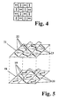
- This two-stage irradiation with different masks and different linearly polarized light creates an orientation pattern in the photopolymer layer, as shown in FIG. 4.
- the adjoining square areas each have a staggered preferred orientation of the polymer molecules.
- the liquid crystal molecules orient themselves in accordance with the changing orientations of the photopolymer layer.
- FIG. 5 An example of such a display, in which pixels with a first helix angle ⁇ 1 with pixels with a second helix angle ⁇ 2 of the liquid crystal in between are arranged in a grid pattern, is shown in FIG. 5.
- the two plates are shown with the preferred orientations.
- the lower plate 14 has a preferred orientation ⁇ 11 in a first set 15 of the surface areas arranged in a grid, in the second set 16 the preferred orientation ⁇ 12 , where a is the angle of the preferred orientation with respect to a substrate edge.
- the upper plate 17 accordingly has a first set 18 of surface areas with preferred orientation u 21 and a second set 19 of surface areas with preferred orientation a 22 .
- cholesteric additives which cause a suitable natural twisting in a manner known per se, stable helix configurations with a uniform direction of rotation and 70 ° ⁇
- a glass plate was coated with a 2% solution of polyvinyl cinnamate (mol. Wt. - 15000) in methyl cellosolve acetate in a spin coating process at 3000 rpm for about 30 s.
- the thickness of the layer produced in this way was approximately 0.1 ⁇ .
- the layer was then approx. 20 min. air-dried and then heated to approx. 80 ° -90 ° C for approx. 20 s.
- the layer was exposed to the linearly polarized light of an HgHP lamp with a wavelength of approximately 365 nm for approximately 100 s, first through the positive mask 8 and then with um 90 rotated direction of polarization through the complementary or negative mask 9.
- the irradiation energy was in each case approximately 15 mW / cm 2 .
- a cell which was filled with a nematic liquid crystal, was built from the plates prepared in this way in a manner known per se. Depending on whether one or both plates have an orientation pattern, it may be necessary to make precise adjustments. It was found that the liquid crystal layer was planarly oriented in two preferred directions, and in such a way that the nematic director of the liquid crystal layer was oriented in accordance with the changing orientation in the photopolymer layers.
- Example 2 In a procedure similar to that in Example 1, a layer of a solution of a polyvinyl ester of paramethoxycinnamic acid (molecular weight approx. 15000-50000) in chlorobenzene and dichlorethylene was exposed 1: 1 for approx. 10 s to an irradiation power of approx. 0.5 J / cm 2 . The resulting layer also induces a parallel orientation in an adjacent liquid crystal.
- a glass plate was immersed in a 1% solution of coated in water.
- a liquid crystal cell constructed with plates coated in this way was filled with a nematic liquid crystal and, for better orientation of the liquid crystal, heated to 100 ° C. for about 5 minutes so that the liquid crystal reached its isotropic state, and then cooled. The liquid crystal was then planar.
- a glass plate was covered with a 3% solution of evaporated in chloroform.
- the resulting layer approx. 1000-2000 ⁇ thick, was irradiated with light of the wavelength ⁇ 400-550 with an output of approx. 45 mW / cm 2 for approx. 3 min.
- Example 3 With plates coated in this way, a liquid crystal cell was built as in Example 3, in which the liquid crystal was likewise planar.
- Example 1 was repeated, but instead of linearly polarized light, unpolarized light was used in the second exposure step. After assembly of the liquid crystal cell, it was found that the areas photopolymerized with linearly polarized light oriented the liquid crystal layer planar in a preferred direction, whereas the liquid crystal in the areas irradiated with unpolarized light Areas has no preferred direction.
Abstract
Description
Die Erfindung betrifft Flüssigkristallanzeigezellen die aus einem orientierten Flüssigkristall zwischen zwei mit transparenten Elektrodenschichten und Orientierungsschichten versehenen Platten (Substraten) bestehen.The invention relates to liquid crystal display cells which consist of an oriented liquid crystal between two plates (substrates) provided with transparent electrode layers and orientation layers.
In Flüssigkristallanzeigezellen, die auf einem elektrischen Feldeffekt beruhen, sind die den Flüssigkristall begrenzenden Glas- oder Kunstoffplatten auf den dem Flüssigkristall zugewandten Oberflächen mit Beschichtungen versehen, welche die unmittelbar angrenzenden Flüssigkristallmoleküle entlang einer Vorzugsrichtung orientieren. Dies gilt für Flüssigkristallanzeigen, die auf dem sog. Drehzellen (twisted nematic, TN)-Effekt, und solche, die auf höherer Verdrillung beruhen, z.B. sog. Super Twisted Nematic (STN)-Zellen, sowie schliesslich auch für ferroelektrische Flüssigkristallzellen.In liquid crystal display cells which are based on an electrical field effect, the glass or plastic plates which delimit the liquid crystal are provided on the surfaces facing the liquid crystal with coatings which orient the immediately adjacent liquid crystal molecules along a preferred direction. This applies to liquid crystal displays based on the so-called twisted nematic (TN) effect, and those based on higher twist, e.g. So-called Super Twisted Nematic (STN) cells, and finally also for ferroelectric liquid crystal cells.
Bisher wurde die Wandorientierung der Flüssigkristallmoleküle in Anzeigezellen entweder durch Schrägbedampfen der Substratoberfläche mit SiOx, oder aber heute praktisch ausschliesslich durch mechanische Behandlung (Reiben) einer Polymerschicht erzeugt, die zuvor auf die Substratoberfläche(n) aufgebracht wurde. Diese Reibmethode erlaubt es nicht, selektive Gebiete der Substratoberfläche mit einer Vorzugsorientierung zu versehen. Insbesondere ist es mit bisherigen Methoden nicht möglich, Orientierungsmuster herzustellen, wie z.B. eine von Bildpunkt (Pixel) zu Bildpunkt verschiedene Wandorientierung. Ausserdem beeinträchtigt das heute beinahe ausschliesslich angewendete Reiben einer Polymerschicht häufig die Ausbeuten bei der Herstellung von aktiv adressierten Drehzellen dadurch, dass die beim Reiben entstehende elektrostatische Aufladung des Substrates zu elektrischen Durchbrüchen in den Dünnfilmtransistoren auf der Substratoberfläche führt.So far, the wall orientation of the liquid crystal molecules in display cells has been generated either by oblique vapor deposition of the substrate surface with SiO x , or today practically exclusively by mechanical treatment (rubbing) of a polymer layer that was previously applied to the substrate surface (s). This rubbing method does not allow selective areas of the substrate surface to be given a preferred orientation. In particular, it has not been possible with previous methods to produce orientation patterns, such as a wall orientation that differs from pixel (pixel) to pixel. In addition, the almost exclusively applied rubbing of a polymer layer frequently affects the yields in the production of actively addressed rotary cells in that the electrostatic charging of the substrate that occurs during rubbing leads to electrical breakdowns in the thin-film transistors on the substrate surface.
Der Erfindung liegt die Aufgabe zugrunde, eine neue und verbesserte Möglichkeit der Oberflächenorientierung von Flüssigkristallen anzugeben, die die Nachteile der bekannten Methoden vermeidet und vor allem die Möglichkeit der Herstellung von Orientierungsmustern beinhaltet.The invention is based on the object of specifying a new and improved possibility of surface orientation of liquid crystals which avoids the disadvantages of the known methods and, above all, includes the possibility of producing orientation patterns.
Erfindungsgemäss wird dies dadurch erreicht, dass bei einer Flüssigkristallzelle der eingangs erwähnten Art auf die mit den Elektroden versehenen Innenseiten der Platten orientierte Photopolymerschichten aufgebracht sind, welche die angrenzenden Flüssigkristallmoleküle in eine Vorzugsrichtung ausrichten.This is achieved according to the invention in that, in the case of a liquid crystal cell of the type mentioned at the outset, oriented photopolymer layers which align the adjacent liquid crystal molecules in a preferred direction are applied to the inside of the plates provided with the electrodes.
Für den Zweck der vorliegenden Beschreibung wird ein Polymer, dessen Polymerisation durch Lichteinwirkung ausgelöst oder bewirkt wurde als Photopolymer bezeichnet. Im übrigen wird auch Bezug genommen auf das schweizerische Patentgesuch Nr. 2244/91 mit dem Titel "Orientierte Photopolymere und Verfahren zu deren Herstellung".For the purpose of the present description, a polymer whose polymerization has been triggered or caused by exposure to light is referred to as a photopolymer. For the rest, reference is also made to the Swiss patent application No. 2244/91 with the title "Oriented photopolymers and processes for their production".
Vorzugsweise sind die Vorzugsrichtungen an den beiden Platten verschieden.The preferred directions on the two plates are preferably different.
Besonders bevorzugt wird ein nematischer Flüssigkristall durch die Orientierungsschichten planar in eine Vorzugsrichtung orientiert, wobei der Winkel 0 zwischen dem nematischen Direktor und der Substratoberfläche 0 6 e < 85 ° ist.A nematic liquid crystal is particularly preferably oriented planar in a preferred direction by the orientation layers, the angle 0 between the nematic director and the substrate surface being 0 6 e <85 °.
Gemäss einer bevorzugten Ausführungsform der Erfindung ist ein Muster aus Bereichen mit unterschiedlichen Vorzugsorientierungen oder ein Muster aus Bereichen mit Vorzugsorientierung und unorientierten Bereichen vorhanden.According to a preferred embodiment of the invention, there is a pattern from areas with different preferred orientations or a pattern from areas with preferred orientation and unoriented areas.
Gemäss einer weiteren bevorzugten Ausführungsform weisen die beiden Platten unterschiedliche Orientierungsmuster auf, die sich durch unterschiedliche Vorzugsorientierungen unterscheiden, was zu unterschiedlichen Verdrillungswinkeln führt.According to a further preferred embodiment, the two plates have different orientation patterns, which differ in different preferred orientations, which leads to different twist angles.
Es wurde überraschend gefunden, dass orientierte Photopolymerschichten, d.h. Photopolymere die durch Einstrahlen von linear polarisiertem Licht polymerisiert sind, Flüssigkristalle, die mit ihnen in Kontakt kommen, in eine Vorzugsrichtung orientieren. Dies gilt nicht nur für die Vorzugsrichtung parallel zu den Platten. Durch die orientierten Photopolymere kann auch ein Kippwinkel in Richtung senkrecht zu den Platten induziert.It has surprisingly been found that oriented photopolymer layers, i.e. Photopolymers that are polymerized by irradiation of linearly polarized light, orient liquid crystals that come into contact with them in a preferred direction. This does not only apply to the preferred direction parallel to the plates. The oriented photopolymers can also induce a tilt angle in the direction perpendicular to the plates.
Dadurch wird die Herstellung von Oberflächenorientierungsschichten in Flüssigkristallanzeigezellen ohne SiOx- Bedampfung und ohne geriebene Polymere erstmals möglich.This enables the production of surface orientation layers in liquid crystal display cells without SiO x vapor deposition and without rubbed polymers for the first time.
Die Verwendung von Orientierungsschichten aus Photopolymeren erlaubt erstmals auch die Erzeugung von Orientierungsmustern, indem photographische Masken mit linear polarisiertem Licht einer gewünschten Schwingungsrichtung bestrahlt und auf das beschichtete Substrat abgebildet werden. Als Alternative können auch interferometrische Abbildungstechniken angewandt werden (polarisierte Hologramme).For the first time, the use of orientation layers made of photopolymers also enables the generation of orientation patterns by irradiating photographic masks with linearly polarized light in a desired direction of oscillation and imaging them on the coated substrate. As an alternative, interferometric imaging techniques can also be used (polarized holograms).
Im folgenden werden anhand der beiliegenden Zeichnung und der Beispiele Ausführungsformen der Erfindung näher erläutert. Es zeigen
- Fig. 1 eine Flüssigkristallanzeigezelle nach der Erfindung
- Fig. 2 eine Vorrichtung zur Herstellung einer Orientierungsschicht
- Fig. 3 einen Maskensatz zur Verwendung in der Vorrichtung nach Fig. 1
- Fig. 4-5 verschiedene Orientierungsmuster als Ergebnis der Belichtung mit dem Maskensatz gemäss Fig. 3.
- Fig. 1 shows a liquid crystal display cell according to the invention
- Fig. 2 shows a device for producing an orientation layer
- 3 shows a mask set for use in the device according to FIG. 1
- 4-5 different orientation patterns as a result of the exposure with the mask set according to FIG. 3.
Die in Fig. 1 schematisch im Schnitt gezeigte Flüssigkristallzelle besteht wie üblich aus zwei transparenten Platten 1, 2 und einer dazwischenliegenden Flüssigkristallschicht 7. Die beiden Platten aus Glas oder Kunststoff sind mit Ansteuerelektroden 3,4 und mit darüberliegenden Orientierungsschichten 5, 6 versehen. Im Unterschied zu vorbekannten Flüssigkristallzellen bestehen die Orientierungsschichten aus orientiertem Photopolymer.The liquid crystal cell shown schematically in FIG. 1, as usual, consists of two
In der in Fig. 2 gezeigten einfachen Vorrichtung zur Herstellung der orientierten Photopolymerschichten ist eine Glasplatte 1 mit einer transparenten, leitenden Elektrodenschicht 2 und mit einer Schicht 3 aus einem photopolymerisierbaren organischen Material versehen. Die Schicht wird mittels einer Linse 4 und einer vorgesetzten Maske 5 mit linear polarisiertem Licht bestrahlt. Dieses kommt von einem Polarisator 6, der mit unpolarisiertem UV-Licht 7 beleuchtet wird.In the simple device for producing the oriented photopolymer layers shown in FIG. 2, a
Die Maske 5 ist in Fig. 3 als Maskensatz gezeigt, der aus zwei komplementären Masken 8, 9 oder mit anderen Worten aus einer positiven Maske 8 (Fig. 3a) und einer negativen Maske 9 (Fig. 3b) besteht. Die beiden Masken zeigen ein schachbrettartiges Muster, d.h. sie decken abwechselnd gleich grosse Quadrate 10 der gesamten Zellenfläche ab und lassen die jeweils anderen quadratischen Flächen 11 frei.The
Bestrahlung durch die positive Maske 8 mit linear polarisiertem Licht mit der durch den Pfeil 12 angegebenen Polarisationsrichtung bewirkt die orientierte Polymerisation der von der Maske frei gelassenen Flächen der dahinter angeordneten polymerisierbaren Schicht 2. Nach diesem ersten Schritt wird die Maske 8 durch die negative Maske 9 ersetzt und die polymerisierbare Schicht 3 mit Licht bestrahlt, dessen Polarisationsrichtung gemäss dem Pfeil 12 um 90 gedreht ist. Die nunmehr freien Flächen der Schicht polymerisieren mit entsprechend gedrehter Orientierung.Irradiation through the
Wenn im ersten Schritt vollständige Polymerisation erreicht wurde, ist für den zweiten Schritt keine Maske mehr erforderlich, weil die im ersten Schritt induzierte Orientierung erhalten bleibt.If complete polymerization has been achieved in the first step, a mask is no longer required for the second step because the orientation induced in the first step is retained.
Durch diese zweistufige Bestrahlung mit verschiedenen Masken und unterschiedlich linear polarisiertem Licht entsteht ein Orientierungsmuster in der Photopolymerschicht, wie es in Fig. 4 gezeigt ist. Die jeweils aneinandergrenzenden quadratischen Bereiche weisen gegeneinander versetzte Vorzugsorientierung der Polymermoleküle auf. In einer Flüssigkristallzelle, die mit derart beschichteten Platten aufgebaut ist, orientieren sich die Flüssigkristallmoleküle entsprechend den wechselnden Orientierungen der Photopolymerschicht.This two-stage irradiation with different masks and different linearly polarized light creates an orientation pattern in the photopolymer layer, as shown in FIG. 4. The adjoining square areas each have a staggered preferred orientation of the polymer molecules. In a liquid crystal cell which is constructed with plates coated in this way, the liquid crystal molecules orient themselves in accordance with the changing orientations of the photopolymer layer.
Anstelle der von Bereich zu Bereich um 90 versetzten Orientierung sind auch andere Winkelkombinationen möglich. Vor allem ist es möglich, die Orientierungsrichtungen voneinander in der Zelle gegenüberliegenden Bereichen so vorzusehen, dass die Verdrillungswinkel bzw. die Ganghöhen der dazwischenliegenden Volumenbereiche des Flüssigkristalls von Bereich zu Bereich variieren. Durch geeignete chirale Dotierung des nematischen Flüssigkristalls lassen sich so in einer einzigen Anzeige TN-Bereiche und STN-Bereiche nebeneinander verwirklichen. Dies kann von Bedeutung sein, wenn in einer Anzeige sowohl grossflächige Informationen als auch komplexe, d.h. Multiplexansteuerung erfordernde Informationen dargestellt werden sollen. Auch lassen sich verschieden stark verdrillte STN-Zellen in ein und derselben Anzeige realisieren.Instead of the orientation shifted from area to area by 90, other angle combinations are also possible. Above all, it is possible to provide the directions of orientation opposite one another in the cell in such a way that the twist angles or the pitch of the intervening volume regions of the liquid crystal vary from region to region. Suitable chiral doping of the nematic liquid crystal allows TN regions and STN regions to be realized side by side in a single display. This can be important if both large-scale information and complex, i.e. Information requiring multiplex control should be displayed. Different twisted STN cells can also be realized in one and the same display.
Ein Beispiel einer solchen Anzeige, bei der Bildpunkte mit einem ersten Helixwinkel φ1mit Bildpunkten mit einem zweiten Helixwinkel φ2 des jeweils dazwischenliegenden Flüssigkristalls rasterförmig angeordnet sind, ist in Fig. 5 gezeigt. Dargestellt sind die beiden Platten mit den Vorzugsorientierungen.An example of such a display, in which pixels with a first helix angle φ 1 with pixels with a second helix angle φ 2 of the liquid crystal in between are arranged in a grid pattern, is shown in FIG. 5. The two plates are shown with the preferred orientations.
Die untere Platte 14 hat in einerersten Menge 15 der rasterförmig angeordneten Flächenbereiche eine Vorzugsorientierung α11, in der zweiten Menge 16 die Vorzugsorientierung α12, wobei a der Winkel der Vorzugsorientieurng gegenüber einer Substratkante ist.The
Die obere Platte 17 hat entsprechend eine erste Menge 18 von Flächenbereichen mit Vorzugsorientierung u21 und eine zweite Menge 19 von Flächenbereichen mit Vorzugsorientierung a22. Durch geeignete Justierung der Platten in einer Flüssigkristallzelle ergeben sich für den dazwischenliegenden Flüssigkristall die Helixwinkel φ1 = α11 - a12 bzw. φ2 = α21- α22. Durch Dotierung mit cholesterischen Zusätzen, die in an sich bekannter Weise eine geeignete natürliche Verdrillung bewirken, können stabile Helixkonfigurationen mit einheitlichem Drehsinn und 70 ° ≦|φ1 - φ2 ≦ 220 erreicht werden.The
Im folgenden werden einige zur Erläuterung der Erfindung durchgeführte Beispiele beschrieben.In the following some examples are given to illustrate the invention.
Eine Glasplatte wurde mit einer 2%igen Lösung von Polyvinylcinnamat (Mol. Gew. - 15000) in Methylcellosolveacetat in einem Spin-Coating Verfahren mit 3000 Upm ca. 30 s beschichtet. Die Dicke der so hergestellten Schichtbetrug ca. 0.1u. Danach wurde die Schicht ca. 20 min. an der Luft getrocknet und anschliessend während ca. 20 s auf ca. 80 ° -90 ° C erhitzt. Nach dieser Vorbehandlung wurde die Schicht während ca. 100 s der Bestrahlung mit dem linear polarisierten Licht einer HgHP-Lampe mit einer Wellenlänge von ca. 365 nm ausgesetzt, und zwar zuerst durch die positive Maske 8 und danach mit um 90 gedrehter Polarisationsrichtung durch die komplementäre oder negative Maske 9. Die Bestrahlungsenergie betrug jeweils ca. 15 mW/cm2.A glass plate was coated with a 2% solution of polyvinyl cinnamate (mol. Wt. - 15000) in methyl cellosolve acetate in a spin coating process at 3000 rpm for about 30 s. The thickness of the layer produced in this way was approximately 0.1µ. The layer was then approx. 20 min. air-dried and then heated to approx. 80 ° -90 ° C for approx. 20 s. After this pretreatment, the layer was exposed to the linearly polarized light of an HgHP lamp with a wavelength of approximately 365 nm for approximately 100 s, first through the
Aus den so vorbereiteten Platten wurde in an sich bekannter Weise eine Zelle gebaut, die mit einem nematischen Flüssigkristall gefüllt wurde. Je nachdem ob eine oder beide Platten ein Orientierungsmuster aufweisen, muss gegebenenfalls auf genaue Justierung geachtet werden. Es wurde festgestellt, dass die Flüssigkristallschicht in zwei Vorzugsrichtungen planar orientiert war und zwar so, dass der nematische Direktor der Flüssigkristallschicht entsprechend der wechselnden Orientierung in den Photopolymerschichten ausgerichtet war.A cell, which was filled with a nematic liquid crystal, was built from the plates prepared in this way in a manner known per se. Depending on whether one or both plates have an orientation pattern, it may be necessary to make precise adjustments. It was found that the liquid crystal layer was planarly oriented in two preferred directions, and in such a way that the nematic director of the liquid crystal layer was oriented in accordance with the changing orientation in the photopolymer layers.
In einem ähnlichen Vorgehen wie in Beispiel 1 wurde eine Schicht aus einer Lösung eines Polyvinylesters der Paramethoxyzimtsäure (Molekulargewicht ca. 15000-50000) in Chlorobenzol und Dichloräthylen 1:1 während ca. 10 s einer Bestrahlungsleistung von ca. 0.5 J/cm2 ausgesetzt. Die entstehende Schicht induziert ebenfalls eine parallele Orientierung in einem angrenzenden Flüssigkristall.In a procedure similar to that in Example 1, a layer of a solution of a polyvinyl ester of paramethoxycinnamic acid (molecular weight approx. 15000-50000) in chlorobenzene and dichlorethylene was exposed 1: 1 for approx. 10 s to an irradiation power of approx. 0.5 J / cm 2 . The resulting layer also induces a parallel orientation in an adjacent liquid crystal.
Eine Glasplatte wurde in einem Tauchverfahren mit einer 1 %igen Lösung von

in Wasser beschichtet. Die so entstandene Schicht hat eine Dicke von ca. 0,07µ und wurde mit linear polarisiertem Licht mit einer Wellenlänge = = 400-500 nm und einer Bestrahlungsleistung von ca. 47 mW/cm2 während ca. 8 min. bestrahlt.A glass plate was immersed in a 1% solution of
coated in water. The resulting layer has a thickness of approx. 0.07µ and was linearly polarized light with a wavelength = = 400-500 nm and an irradiation power of approx. 47 mW / cm 2 for approx. 8 min. irradiated.
Eine mit derart beschichteten Platten aufgebaute Flüssigkristallzelle wurde mit einem nematischen Flüssigkristall gefüllt und zwecks besserer Orientierung des Flüssigkristalls etwa 5 min auf 100°C erhitzt, damit der Flüssigkristall seinen isotropen Zustand erreicht, und danach abgekühlt. Der Flüssigkristall war danach planar orientiert.A liquid crystal cell constructed with plates coated in this way was filled with a nematic liquid crystal and, for better orientation of the liquid crystal, heated to 100 ° C. for about 5 minutes so that the liquid crystal reached its isotropic state, and then cooled. The liquid crystal was then planar.
Eine Glasplatte wurde mit einer 3%igen Lösung von

in Chloroform bedampft. Die so entstandene, ca. 1000-2000 Ä dicke Schicht wurde mit Licht der Wellenlänge λ≈ 400-550 mit einer Leistung von ca. 45 mW/cm2 während ca. 3 min bestrahlt.A glass plate was covered with a 3% solution of
evaporated in chloroform. The resulting layer, approx. 1000-2000 Å thick, was irradiated with light of the wavelength λ≈ 400-550 with an output of approx. 45 mW / cm 2 for approx. 3 min.
Mit derart beschichteten Platten wurde wie im Beispiel 3 eine Flüssigkristallzelle gebaut in der der Flüssigkristall ebenfalls planar orientiert war.With plates coated in this way, a liquid crystal cell was built as in Example 3, in which the liquid crystal was likewise planar.
Beispiel 1 wurde wiederholt, jedoch an Stelle von linear polarisiertem Licht wurde im zweiten Belichtungsschritt unpolarisiertes Licht verwendet. Nach dem Zusammenbau der Flüssigkristallzelle wurde festgestellt, dass die mit linear polarisiertem Licht photopolymerisierten Gebiete die Flüssigkristallschicht in eine Vorzugsrichtung planar orientierten, wogegen der Flüssigkristall in den mit unpolarisiertem Licht bestrahlten Gebieten keine Vorzugsrichtung aufweist.Example 1 was repeated, but instead of linearly polarized light, unpolarized light was used in the second exposure step. After assembly of the liquid crystal cell, it was found that the areas photopolymerized with linearly polarized light oriented the liquid crystal layer planar in a preferred direction, whereas the liquid crystal in the areas irradiated with unpolarized light Areas has no preferred direction.
Claims (6)
Applications Claiming Priority (4)
| Application Number | Priority Date | Filing Date | Title |
|---|---|---|---|
| CH2246/91 | 1991-07-26 | ||
| CH224691 | 1991-07-26 | ||
| CH10092 | 1992-01-14 | ||
| CH100/92 | 1992-01-14 |
Publications (3)
| Publication Number | Publication Date |
|---|---|
| EP0525478A2 true EP0525478A2 (en) | 1993-02-03 |
| EP0525478A3 EP0525478A3 (en) | 1993-08-04 |
| EP0525478B1 EP0525478B1 (en) | 1997-06-11 |
Family
ID=25683519
Family Applications (1)
| Application Number | Title | Priority Date | Filing Date |
|---|---|---|---|
| EP92111775A Expired - Lifetime EP0525478B1 (en) | 1991-07-26 | 1992-07-10 | Liquid crystal display cell |
Country Status (6)
| Country | Link |
|---|---|
| US (1) | US5838407A (en) |
| EP (1) | EP0525478B1 (en) |
| JP (1) | JP2608661B2 (en) |
| DE (1) | DE59208605D1 (en) |
| HK (1) | HK1007198A1 (en) |
| SG (1) | SG50586A1 (en) |
Cited By (45)
| Publication number | Priority date | Publication date | Assignee | Title |
|---|---|---|---|---|
| EP0611981A1 (en) * | 1993-02-17 | 1994-08-24 | F. Hoffmann-La Roche Ag | Optical device |
| WO1995018989A2 (en) * | 1994-01-10 | 1995-07-13 | Honeywell Inc. | Method of fabricating multi-domain, liquid crystal displays |
| WO1995034843A1 (en) * | 1994-06-13 | 1995-12-21 | Merck Patent Gmbh | Electro-optical system |
| EP0689084A1 (en) * | 1994-06-24 | 1995-12-27 | F. Hoffmann-La Roche AG | Optical component |
| EP0708354A1 (en) * | 1994-10-14 | 1996-04-24 | International Business Machines Corporation | Liquid crystal display device and method of manufacture |
| EP0684500A3 (en) * | 1994-05-27 | 1996-07-24 | Sharp Kk | Liquid crystal display device, method for producing the same, and apparatus for producing the same. |
| EP0742471A2 (en) * | 1995-05-10 | 1996-11-13 | Stanley Electric Co., Ltd. | Arrangement for rubbingless orientation of liquid crystals with tilt |
| US5578351A (en) * | 1995-01-20 | 1996-11-26 | Geo-Centers, Inc. | Liquid crystal composition and alignment layer |
| EP0753785A1 (en) * | 1995-07-11 | 1997-01-15 | F. Hoffmann-La Roche Ag | Transfer of polarisation patterns to polarisation sensitive photolayers |
| FR2741353A1 (en) * | 1995-11-20 | 1997-05-23 | Lg Electronics Inc | PHOTOSENSITIVE SUBSTANCE FOR THE ORIENTATION OF A LIQUID CRYSTAL DEVICE AND LIQUID CRYSTAL DEVICE OBTAINED THEREOF |
| GB2318190A (en) * | 1996-10-02 | 1998-04-15 | Lg Electronics Inc | Method for fabricating an LCD with a photo-oriented alignment layer |
| US5855968A (en) * | 1993-07-30 | 1999-01-05 | Sharp Kabushiki Kaisha | Liquid crystal display device and method for producing the same |
| US5912717A (en) * | 1996-02-05 | 1999-06-15 | Stanley Electric Co., Ltd. | Homeotropic liquid crystal display and its manufacture |
| US6013335A (en) * | 1993-07-30 | 2000-01-11 | Sharp Kabushiki Kaisha | Liquid crystal display apparatus and method for processing the same |
| US6124970A (en) * | 1997-10-20 | 2000-09-26 | Latents Image Technology Ltd. | Polymer materials with latent images visible in polarized light and methods for their production |
| US6160597A (en) * | 1993-02-17 | 2000-12-12 | Rolic Ag | Optical component and method of manufacture |
| US6191836B1 (en) | 1996-11-07 | 2001-02-20 | Lg Philips Lcd, Co., Ltd. | Method for fabricating a liquid crystal cell |
| US6226066B1 (en) | 1996-01-09 | 2001-05-01 | Lg. Philips Lcd Co., Ltd. | Method for controlling pretilt angle direction in a liquid crystal cell |
| US6271906B1 (en) | 1991-12-05 | 2001-08-07 | Rolic Ag | Liquid crystal cells for integrated optical components and a method of manufacturing them |
| US6292296B1 (en) | 1997-05-28 | 2001-09-18 | Lg. Philips Lcd Co., Ltd. | Large scale polarizer and polarizer system employing it |
| US6383579B1 (en) | 1999-04-21 | 2002-05-07 | Lg. Philips Lcd Co., Ltd. | Liquid crystal display device |
| US6399165B1 (en) | 1997-11-21 | 2002-06-04 | Lg. Philips Lcd Co., Ltd. | Liquid crystal display device |
| US6479218B1 (en) | 1999-10-14 | 2002-11-12 | Lg Philips Lcd Co., Ltd | Method for manufacturing multi-domain liquid crystal cell |
| SG94794A1 (en) * | 1993-02-17 | 2003-03-18 | Rolic Ag | Optical component |
| US6627269B2 (en) | 2000-12-05 | 2003-09-30 | Lg.Philips Lcd Co., Ltd. | Photo-alignment material and liquid crystal display device |
| US6764724B1 (en) | 1999-03-25 | 2004-07-20 | Lg.Philips Lcd Co., Ltd. | Alignment layer for a liquid crystal display device |
| US6770335B2 (en) | 2000-10-28 | 2004-08-03 | Lg.Philips Lcd Co., Ltd. | Photoalignment materials and liquid crystal display device and method for fabricating the same with said materials |
| US6793987B2 (en) | 2000-10-28 | 2004-09-21 | Lg.Philips Lcd Co., Ltd. | Photoalignment materials and liquid crystal display fabricated with such photoalignment materials |
| DE19744267B4 (en) * | 1996-10-07 | 2005-07-28 | Lg. Philips Lcd Co., Ltd. | Method for controlling the tilt angle in a liquid crystal cell |
| US7060332B2 (en) | 2001-04-25 | 2006-06-13 | Lg.Philips Lcd Co., Ltd. | Liquid crystal display with alignment film of polyphenylenphthalamide-based material and method for fabricating the same |
| DE19703682B4 (en) * | 1996-02-01 | 2006-08-10 | Lg. Philips Lcd Co., Ltd. | UV light irradiation apparatus for photo alignment method and irradiation method using the same |
| EP1767523A1 (en) * | 2004-06-30 | 2007-03-28 | Dainippon Ink and Chemicals, Incorporated | Azo compound, composition for optical alignment film using same, and method for producing optical alignment film |
| CN100410776C (en) * | 2004-06-30 | 2008-08-13 | 乐金显示有限公司 | Liquid crystal display device and method for fabricating the same |
| WO2008130559A2 (en) | 2007-04-16 | 2008-10-30 | North Carolina State University | Methods of fabricating switchable liquid crystal polarization gratings on reflective substrates and related devices |
| EP2302425A1 (en) | 1997-05-09 | 2011-03-30 | Rolic AG | Optical element |
| EP2309292A3 (en) * | 2001-11-08 | 2011-11-23 | Dai Nippon Printing Co., Ltd. | A liquid crystal display device |
| US8305523B2 (en) | 2007-04-16 | 2012-11-06 | North Carolina State University | Multi-layer achromatic liquid crystal polarization gratings and related fabrication methods |
| US8339566B2 (en) | 2007-04-16 | 2012-12-25 | North Carolina State University | Low-twist chiral liquid crystal polarization gratings and related fabrication methods |
| US8659711B2 (en) | 2001-11-08 | 2014-02-25 | Dai Nippon Printing Co., Ltd. | Phase difference layer laminated body for three dimensional liquid crystal display device and manufacturing method thereof |
| CN104635373A (en) * | 2015-02-13 | 2015-05-20 | 上海天马微电子有限公司 | Liquid crystal display panel and liquid crystal display device |
| CN104884982A (en) * | 2012-12-31 | 2015-09-02 | Lg化学株式会社 | Optical element |
| US9298041B2 (en) | 2007-04-16 | 2016-03-29 | North Carolina State University | Multi-twist retarders for broadband polarization transformation and related fabrication methods |
| US10207474B2 (en) | 2015-01-28 | 2019-02-19 | Zeon Corporation | Multilayer film, optically anisotropic layered body, circularly polarizing plate, organic electroluminescence display device, and manufacturing method |
| CN110192145A (en) * | 2016-11-18 | 2019-08-30 | 奇跃公司 | Liquid crystal diffraction equipment and its manufacturing method with nano-scale patterns |
| US11586065B2 (en) | 2016-11-18 | 2023-02-21 | Magic Leap, Inc. | Spatially variable liquid crystal diffraction gratings |
Families Citing this family (61)
| Publication number | Priority date | Publication date | Assignee | Title |
|---|---|---|---|---|
| JP2693368B2 (en) * | 1993-06-29 | 1997-12-24 | スタンレー電気株式会社 | Liquid crystal display device and method of manufacturing the same |
| JP2768262B2 (en) * | 1994-02-24 | 1998-06-25 | 日本電気株式会社 | Transmissive liquid crystal display |
| TW515926B (en) | 1996-07-10 | 2003-01-01 | Matsushita Electric Ind Co Ltd | Liquid crystal alignment film and method for producing the same, and liquid crystal display apparatus using the same and method for producing the same |
| KR100247137B1 (en) * | 1996-07-29 | 2000-03-15 | 구본준 | Method for manufacturing multi-domain lc cell |
| EP1065553A4 (en) * | 1998-03-19 | 2005-03-09 | Matsushita Electric Ind Co Ltd | Resin-liquid crystal formed body, liquid crystal device, liquid crystal display comprising the same, and methods of manufacturing the same |
| JP3620312B2 (en) | 1998-10-30 | 2005-02-16 | 株式会社日立製作所 | Liquid crystal display |
| US20040120040A1 (en) * | 1998-11-13 | 2004-06-24 | Rolic Ag | Optical component |
| US6610462B1 (en) | 1999-08-13 | 2003-08-26 | Rolic Ag | Liquid crystal alignment using photo-crosslinkable low molecular weight materials |
| US6239853B1 (en) * | 1999-10-01 | 2001-05-29 | Rockwell Science Center, Llc | Staggered waveplate LCD privacy screen |
| AU7638600A (en) | 1999-10-19 | 2001-04-30 | Rolic Ag | Topologically structured polymer coating |
| EP1170624A1 (en) * | 2000-07-05 | 2002-01-09 | Rolic AG | Nematic liquid crystal electrooptical element and device |
| ATE443279T1 (en) * | 2000-07-05 | 2009-10-15 | Rolic Ag | ELECTRO-OPTICAL ELEMENT AND DEVICE USING NEMATIC LIQUID CRYSTALS |
| US6630289B1 (en) * | 2000-08-22 | 2003-10-07 | The Hong Kong University Of Science And Technology | Photo-patterned light polarizing films |
| KR100673265B1 (en) | 2000-10-04 | 2007-01-22 | 엘지.필립스 엘시디 주식회사 | Liquid crystal display device |
| EP1203980A1 (en) * | 2000-11-03 | 2002-05-08 | Rolic AG | Switchable color filter |
| US6822713B1 (en) * | 2000-11-27 | 2004-11-23 | Kent State University | Optical compensation film for liquid crystal display |
| US6573963B2 (en) | 2001-02-22 | 2003-06-03 | 3M Innovativeproperties Company | Cholesteric liquid crystal optical bodies and methods of manufacture |
| US6917399B2 (en) * | 2001-02-22 | 2005-07-12 | 3M Innovative Properties Company | Optical bodies containing cholesteric liquid crystal material and methods of manufacture |
| KR100783358B1 (en) * | 2001-04-27 | 2007-12-07 | 엘지.필립스 엘시디 주식회사 | Autostereoscopic display apparatus and fabricating method the same |
| US6876427B2 (en) | 2001-09-21 | 2005-04-05 | 3M Innovative Properties Company | Cholesteric liquid crystal optical bodies and methods of manufacture and use |
| US20030090012A1 (en) * | 2001-09-27 | 2003-05-15 | Allen Richard Charles | Methods of making polarization rotators and articles containing the polarization rotators |
| US6985291B2 (en) * | 2001-10-01 | 2006-01-10 | 3M Innovative Properties Company | Non-inverting transflective assembly |
| JP2004053784A (en) | 2002-07-18 | 2004-02-19 | Sharp Corp | Liquid crystal display device and method for manufacturing the same |
| CN1708724A (en) * | 2002-11-01 | 2005-12-14 | 科比恩公司 | Multi-domain vertical alignment liquid crystal display |
| US7029729B2 (en) * | 2003-02-24 | 2006-04-18 | 3M Innovative Properties Company | Cholesteric liquid crystal additives |
| US7068344B2 (en) * | 2003-02-24 | 2006-06-27 | 3M Innovative Properties Company | Cholesteric liquid crystal optical bodies and methods of manufacture and use |
| US6913708B2 (en) * | 2003-02-24 | 2005-07-05 | 3M Innovative Properties Company | Cholesteric liquid crystal drying process and solvent |
| EP1462485A1 (en) * | 2003-03-26 | 2004-09-29 | Rolic AG | Polymerizable dichroic azo dyes |
| US7160586B2 (en) | 2003-08-29 | 2007-01-09 | 3M Innovative Properties Company | Cholesteric liquid crystal copolymers and additives |
| US7196758B2 (en) * | 2003-12-30 | 2007-03-27 | 3M Innovative Properties Company | Method of alignment of liquid crystals comprising exposing an alignment material to an interference pattern |
| US7564522B2 (en) * | 2004-05-21 | 2009-07-21 | Kopin Corporation | Full symmetrical wide-viewing angle display |
| US20050266175A1 (en) * | 2004-05-27 | 2005-12-01 | Yong Hsu | Retardation coating |
| US7510741B2 (en) * | 2004-06-01 | 2009-03-31 | 3M Innovative Properties Company | Method of making multilayer cholesteric liquid crystal optical bodies |
| EP1764405A1 (en) * | 2005-09-20 | 2007-03-21 | Rolic AG | Functionalized photoreactive compounds |
| US7439000B2 (en) * | 2005-10-25 | 2008-10-21 | 3M Innovative Properties Company | High clarity cholesteric liquid crystal films |
| US7652736B2 (en) * | 2005-10-25 | 2010-01-26 | 3M Innovative Properties Company | Infrared light reflecting film |
| TWI406061B (en) * | 2005-11-10 | 2013-08-21 | Dainippon Ink & Chemicals | Composition for photoalignment film, optically anisotropic body and method of producing same |
| JP4935982B2 (en) * | 2005-11-10 | 2012-05-23 | Dic株式会社 | Composition for photo-alignment film, optical anisotropic body and method for producing the same |
| JP5070977B2 (en) * | 2007-07-31 | 2012-11-14 | 大日本印刷株式会社 | Liquid crystal display element |
| KR101527402B1 (en) * | 2007-12-21 | 2015-06-09 | 롤릭 리미티드 | Photoalignment composition |
| WO2009080147A1 (en) * | 2007-12-21 | 2009-07-02 | Rolic Ag | Functionalized photoreactive compounds |
| DE102008020770B3 (en) * | 2008-04-21 | 2009-10-29 | Bundesdruckerei Gmbh | Security element with an electrically stimulable polarization-dependent volume hologram and method for its production |
| JP5906571B2 (en) | 2010-04-06 | 2016-04-20 | ソニー株式会社 | Liquid crystal display device and method of manufacturing liquid crystal display device |
| US20110262844A1 (en) * | 2010-04-21 | 2011-10-27 | Beam Engineering For Advanced Measurement Co. | Fabrication of high efficiency, high quality, large area diffractive waveplates and arrays |
| JP5549781B2 (en) | 2011-05-31 | 2014-07-16 | Dic株式会社 | Liquid crystal alignment layer comprising cinnamic acid derivative and polymer thereof, and cured product thereof |
| KR101857497B1 (en) | 2011-06-30 | 2018-06-20 | 디아이씨 가부시끼가이샤 | Copolymer, and liquid crystal alignment layer comprising hardened product thereof |
| KR101599756B1 (en) | 2011-06-30 | 2016-03-04 | 디아이씨 가부시끼가이샤 | Cinnamic acid derivative, polymer thereof, and liquid crystal alignment layer comprising hardened product of said polymer |
| US8565058B2 (en) | 2011-12-26 | 2013-10-22 | Asahi Glass Company, Limited | Liquid crystal alignment film, process for its production, optical element using the liquid crystal alignment film, and optical information writing/reading device |
| JP6003192B2 (en) | 2012-04-27 | 2016-10-05 | ソニー株式会社 | Liquid crystal display |
| JP2014081559A (en) | 2012-10-18 | 2014-05-08 | Sony Corp | Liquid crystal display device |
| JP2014095783A (en) | 2012-11-08 | 2014-05-22 | Sony Corp | Liquid crystal display device |
| JP6194657B2 (en) | 2013-06-28 | 2017-09-13 | ソニー株式会社 | Liquid crystal display |
| WO2015080221A1 (en) | 2013-11-29 | 2015-06-04 | Dic株式会社 | Compound, polymer, liquid crystal alignment film, liquid crystal display element, and optical anisotropic body |
| US10442994B2 (en) | 2014-02-19 | 2019-10-15 | Rolic Ag | Liquid crystal alignment composition, liquid crystal alignment film and liquid crystal display element |
| US10126602B2 (en) | 2014-03-20 | 2018-11-13 | Samsung Display Co., Ltd. | Curved display device and fabricating method thereof |
| KR102391559B1 (en) | 2014-05-21 | 2022-04-29 | 롤리크 아게 | Polymerizable dichroic dyes |
| US10120242B2 (en) | 2015-03-20 | 2018-11-06 | Sony Corporation | Liquid crystal display device |
| US9902906B2 (en) * | 2015-04-21 | 2018-02-27 | The United States Of America As Represented By The Secretary Of The Air Force | Voxelated liquid crystal elastomers |
| US11209700B2 (en) | 2016-01-21 | 2021-12-28 | Sharp Kabushiki Kaisha | Method for manufacturing liquid crystal panel, method for manufacturing retardation plate, and wire grid polarizing plate |
| CN205487282U (en) * | 2016-04-06 | 2016-08-17 | 北京京东方光电科技有限公司 | Display module assembly, display device |
| KR102533309B1 (en) | 2017-03-03 | 2023-05-16 | 롤릭 테크놀로지스 아게 | Novel photo-alignment composition for stabilization of pre-tilt angle in liquid crystal layer |
Citations (6)
| Publication number | Priority date | Publication date | Assignee | Title |
|---|---|---|---|---|
| JPS60211427A (en) * | 1984-04-05 | 1985-10-23 | Matsushita Electric Ind Co Ltd | Formation of liquid-crystal oriented film |
| JPS62245218A (en) * | 1986-04-18 | 1987-10-26 | Seiko Epson Corp | Production of liquid crystal display device |
| JPS6327815A (en) * | 1986-07-22 | 1988-02-05 | Victor Co Of Japan Ltd | Manufacture of liquid crystal element |
| JPH01303412A (en) * | 1988-06-01 | 1989-12-07 | Seiko Instr Inc | Liquid crystal element |
| EP0387059A2 (en) * | 1989-03-08 | 1990-09-12 | Hercules Incorporated | Process of aligning liquid crystal media |
| EP0445629A2 (en) * | 1990-03-07 | 1991-09-11 | Hercules Incorporated | Process of preparing liquid crystal compositions containing multiple oriented mesogens |
Family Cites Families (23)
| Publication number | Priority date | Publication date | Assignee | Title |
|---|---|---|---|---|
| JPS545754A (en) * | 1977-06-15 | 1979-01-17 | Toshiba Corp | Twist nematic type liquid crystal display device |
| DE2912467A1 (en) * | 1979-03-29 | 1980-10-09 | Siemens Ag | Sandwich type liq. crystal display - has orientating layer limited to switchable ranges of liq. crystal layer, with rest of support plate coated with opaque and insulating layer |
| JPS5952802B2 (en) * | 1980-04-01 | 1984-12-21 | 大日本印刷株式会社 | Aligned substrate for liquid crystal display and its manufacturing method |
| DE3234074A1 (en) * | 1982-09-14 | 1984-03-15 | Siemens AG, 1000 Berlin und 8000 München | Liquid-crystal cell and its use |
| JPS6060624A (en) * | 1983-09-13 | 1985-04-08 | Matsushita Electric Ind Co Ltd | Liquid crystal display panel and its production |
| JPS6111725A (en) * | 1984-06-26 | 1986-01-20 | Fujitsu Ltd | Liquid crystal display device and its manufacture |
| JPS6151124A (en) * | 1984-08-20 | 1986-03-13 | Matsushita Electric Ind Co Ltd | Liquid crystal display device |
| JPS61121035A (en) * | 1984-11-16 | 1986-06-09 | Seiko Epson Corp | Liquid crystal optical device |
| JPS6291920A (en) * | 1985-10-18 | 1987-04-27 | Victor Co Of Japan Ltd | Liquid crystal display cell |
| GB8608276D0 (en) * | 1986-04-04 | 1986-05-08 | British Telecomm | Optical devices |
| EP0259723B1 (en) * | 1986-09-11 | 1993-04-07 | Siemens Aktiengesellschaft | Process for obtaining heat-resistant structural layers |
| JP2692693B2 (en) * | 1986-10-22 | 1997-12-17 | 富士通株式会社 | LCD panel |
| US4952030A (en) * | 1987-09-04 | 1990-08-28 | Asahi Glass Company, Ltd. | Liquid crystal display device with a 50°-80° twist angle |
| JPH01210932A (en) * | 1988-02-18 | 1989-08-24 | Nec Corp | Orientation of liquid crystal display device |
| JPH0255330A (en) * | 1988-08-22 | 1990-02-23 | Matsushita Electric Ind Co Ltd | Production of oriented film for liquid crystal |
| JP2569406B2 (en) * | 1989-01-25 | 1997-01-08 | 工業技術院長 | Manufacturing method of liquid crystal alignment film using laser |
| JPH02211425A (en) * | 1989-02-13 | 1990-08-22 | Seiko Epson Corp | Liquid crystal oriented film and formation thereof |
| JPH03111818A (en) * | 1989-09-27 | 1991-05-13 | Hitachi Ltd | Optical element and production thereof |
| JPH07101264B2 (en) * | 1990-04-25 | 1995-11-01 | 工業技術院長 | Liquid crystal material alignment method |
| EP0476543B1 (en) * | 1990-09-17 | 1996-08-28 | Matsushita Electric Industrial Co., Ltd. | Liquid crystal alignment film and method of manufacturing the same |
| JP2502802B2 (en) * | 1990-10-15 | 1996-05-29 | インターナシヨナル・ビジネス・マシーンズ・コーポレーシヨン | Liquid crystal display |
| US5473455A (en) * | 1991-12-20 | 1995-12-05 | Fujitsu Limited | Domain divided liquid crystal display device with particular pretilt angles and directions in each domain |
| US5246748A (en) * | 1991-12-23 | 1993-09-21 | Hoechst Celanese Corp. | Thin film optical medium of a multiple amphiphilic bilayer composite |
-
1992
- 1992-07-10 EP EP92111775A patent/EP0525478B1/en not_active Expired - Lifetime
- 1992-07-10 SG SG1996005599A patent/SG50586A1/en unknown
- 1992-07-10 DE DE59208605T patent/DE59208605D1/en not_active Expired - Lifetime
- 1992-07-24 JP JP4198709A patent/JP2608661B2/en not_active Expired - Lifetime
-
1996
- 1996-02-16 US US08/601,310 patent/US5838407A/en not_active Expired - Lifetime
-
1998
- 1998-06-24 HK HK98106393A patent/HK1007198A1/en not_active IP Right Cessation
Patent Citations (6)
| Publication number | Priority date | Publication date | Assignee | Title |
|---|---|---|---|---|
| JPS60211427A (en) * | 1984-04-05 | 1985-10-23 | Matsushita Electric Ind Co Ltd | Formation of liquid-crystal oriented film |
| JPS62245218A (en) * | 1986-04-18 | 1987-10-26 | Seiko Epson Corp | Production of liquid crystal display device |
| JPS6327815A (en) * | 1986-07-22 | 1988-02-05 | Victor Co Of Japan Ltd | Manufacture of liquid crystal element |
| JPH01303412A (en) * | 1988-06-01 | 1989-12-07 | Seiko Instr Inc | Liquid crystal element |
| EP0387059A2 (en) * | 1989-03-08 | 1990-09-12 | Hercules Incorporated | Process of aligning liquid crystal media |
| EP0445629A2 (en) * | 1990-03-07 | 1991-09-11 | Hercules Incorporated | Process of preparing liquid crystal compositions containing multiple oriented mesogens |
Non-Patent Citations (5)
| Title |
|---|
| OKAZAKI M.: 'Exotic Combination of Materials Yields Viable Liquid-Crystal Recording Medium' NIKKEI HIGH TECH REPORT Bd. IV, Nr. 5, 09 Januar 1989, TOKYO, JP, Seiten 7 - 8, XP000035829 * |
| PATENT ABSTRACTS OF JAPAN Bd. 014, Nr. 098 (P-1011) 22 Februar 1990 & JP 01 303412 A (SEIKO INSTRUMENTS & ELECTRONICS) 07 Dezember 1989 * |
| PATENT ABSTRACTS OF JAPAN vol. 10, no. 72 (P-438)(2129) 22. März 1986 & JP-A-60 211 427 ( MATSUSHITA ) 23. Oktober 1985 * |
| PATENT ABSTRACTS OF JAPAN vol. 12, no. 114 (P-688)(2961) 12. April 1988 & JP-A-62 245 218 ( SEIKO EPSON ) 26. Oktober 1987 * |
| PATENT ABSTRACTS OF JAPAN vol. 12, no. 235 (P-725)(3082) 6. Juli 1988 & JP-A-63 027 815 ( VICTOR ) 5. Februar 1988 * |
Cited By (94)
| Publication number | Priority date | Publication date | Assignee | Title |
|---|---|---|---|---|
| US6271906B1 (en) | 1991-12-05 | 2001-08-07 | Rolic Ag | Liquid crystal cells for integrated optical components and a method of manufacturing them |
| EP0611981A1 (en) * | 1993-02-17 | 1994-08-24 | F. Hoffmann-La Roche Ag | Optical device |
| SG94794A1 (en) * | 1993-02-17 | 2003-03-18 | Rolic Ag | Optical component |
| US6160597A (en) * | 1993-02-17 | 2000-12-12 | Rolic Ag | Optical component and method of manufacture |
| US5602661A (en) * | 1993-02-17 | 1997-02-11 | Hoffmann-La Roche Inc. | Optical component |
| US6369869B2 (en) | 1993-02-17 | 2002-04-09 | Rolic A.G. | Optical component and method of manufacture |
| US6717644B2 (en) | 1993-02-17 | 2004-04-06 | Rolic Ag | Optical component and method of manufacture |
| US6013335A (en) * | 1993-07-30 | 2000-01-11 | Sharp Kabushiki Kaisha | Liquid crystal display apparatus and method for processing the same |
| US5855968A (en) * | 1993-07-30 | 1999-01-05 | Sharp Kabushiki Kaisha | Liquid crystal display device and method for producing the same |
| WO1995018989A2 (en) * | 1994-01-10 | 1995-07-13 | Honeywell Inc. | Method of fabricating multi-domain, liquid crystal displays |
| US5657105A (en) * | 1994-01-10 | 1997-08-12 | Honeywell Inc. | Multi-domain liquid crystal displays |
| WO1995018989A3 (en) * | 1994-01-10 | 1995-09-21 | Honeywell Inc | Method of fabricating multi-domain, liquid crystal displays |
| US5604615A (en) * | 1994-05-27 | 1997-02-18 | Sharp Kabushiki Kaisha | Liquid crystal display device and methods for producing same with alignment layer having new bond formation or bond cleavage reaction of molecular chains by light irradiation |
| EP0684500A3 (en) * | 1994-05-27 | 1996-07-24 | Sharp Kk | Liquid crystal display device, method for producing the same, and apparatus for producing the same. |
| WO1995034843A1 (en) * | 1994-06-13 | 1995-12-21 | Merck Patent Gmbh | Electro-optical system |
| EP0689084A1 (en) * | 1994-06-24 | 1995-12-27 | F. Hoffmann-La Roche AG | Optical component |
| US5764326A (en) * | 1994-10-14 | 1998-06-09 | International Business Machines Corporation | Multiple direction rotatable liquid crystal display device and a method for its manufacture |
| EP0708354A1 (en) * | 1994-10-14 | 1996-04-24 | International Business Machines Corporation | Liquid crystal display device and method of manufacture |
| US5578351A (en) * | 1995-01-20 | 1996-11-26 | Geo-Centers, Inc. | Liquid crystal composition and alignment layer |
| EP0742471A3 (en) * | 1995-05-10 | 1997-10-22 | Stanley Electric Co Ltd | Arrangement for rubbingless orientation of liquid crystals with tilt |
| EP0742471A2 (en) * | 1995-05-10 | 1996-11-13 | Stanley Electric Co., Ltd. | Arrangement for rubbingless orientation of liquid crystals with tilt |
| EP0753785A1 (en) * | 1995-07-11 | 1997-01-15 | F. Hoffmann-La Roche Ag | Transfer of polarisation patterns to polarisation sensitive photolayers |
| US6496239B2 (en) | 1995-07-11 | 2002-12-17 | Rolic Ag | Optical component for producing linearly polarized light |
| FR2741353A1 (en) * | 1995-11-20 | 1997-05-23 | Lg Electronics Inc | PHOTOSENSITIVE SUBSTANCE FOR THE ORIENTATION OF A LIQUID CRYSTAL DEVICE AND LIQUID CRYSTAL DEVICE OBTAINED THEREOF |
| US5998563A (en) * | 1995-11-20 | 1999-12-07 | Lg Electronics Inc. | Photosensitive material for orientation of liquid crystal device and liquid crystal device thereof |
| US5824377A (en) * | 1995-11-20 | 1998-10-20 | Lg Electronics Inc. | Photosensitive material for orientation of liquid crystal device and liquid crystal device thereof |
| US6226066B1 (en) | 1996-01-09 | 2001-05-01 | Lg. Philips Lcd Co., Ltd. | Method for controlling pretilt angle direction in a liquid crystal cell |
| US6879363B2 (en) | 1996-01-09 | 2005-04-12 | Lg.Philips Lcd Co., Ltd. | Method for controlling pretilt angle direction in a liquid crystal cell |
| US6433850B2 (en) | 1996-01-09 | 2002-08-13 | Lg. Phillips Lcd Co., Ltd. | Pretilt angle direction in a liquid crystal cell |
| US6633355B2 (en) | 1996-01-09 | 2003-10-14 | Lg. Philips Lcd Co., Ltd. | Method for controlling pretilt angle direction in a liquid crystal cell |
| US7145618B2 (en) | 1996-01-09 | 2006-12-05 | Lg.Philips Lcd Co., Ltd | Method for controlling pretilt angle direction in a liquid crystal cell |
| DE19703682B4 (en) * | 1996-02-01 | 2006-08-10 | Lg. Philips Lcd Co., Ltd. | UV light irradiation apparatus for photo alignment method and irradiation method using the same |
| DE19703682B9 (en) * | 1996-02-01 | 2006-11-23 | Lg. Philips Lcd Co., Ltd. | UV light irradiation apparatus for photo alignment method and irradiation method using the same |
| US5912717A (en) * | 1996-02-05 | 1999-06-15 | Stanley Electric Co., Ltd. | Homeotropic liquid crystal display and its manufacture |
| GB2318190A (en) * | 1996-10-02 | 1998-04-15 | Lg Electronics Inc | Method for fabricating an LCD with a photo-oriented alignment layer |
| GB2318190B (en) * | 1996-10-02 | 1998-08-26 | Lg Electronics Inc | A method of fabricating a liquid crystal display device |
| US5953584A (en) * | 1996-10-02 | 1999-09-14 | Lg Electronics Inc. | Method of fabricating liquid crystal display device having alignment direction determined |
| DE19744267B4 (en) * | 1996-10-07 | 2005-07-28 | Lg. Philips Lcd Co., Ltd. | Method for controlling the tilt angle in a liquid crystal cell |
| US6721025B2 (en) | 1996-11-07 | 2004-04-13 | Lg.Philips Lcd Co., Ltd | Method for fabricating a liquid crystal cell |
| US6417905B1 (en) | 1996-11-07 | 2002-07-09 | Lg. Philips Lcd Co., Ltd. | Method for fabricating a liquid crystal cell |
| US6191836B1 (en) | 1996-11-07 | 2001-02-20 | Lg Philips Lcd, Co., Ltd. | Method for fabricating a liquid crystal cell |
| US6462797B1 (en) | 1996-11-07 | 2002-10-08 | Lg. Philips Lcd Co., Ltd. | Method for fabricating a liquid crystal cell |
| EP2302425A1 (en) | 1997-05-09 | 2011-03-30 | Rolic AG | Optical element |
| EP2302424A1 (en) | 1997-05-09 | 2011-03-30 | Rolic AG | Optical element comprising a structured retarder |
| US6292296B1 (en) | 1997-05-28 | 2001-09-18 | Lg. Philips Lcd Co., Ltd. | Large scale polarizer and polarizer system employing it |
| US6639720B2 (en) | 1997-05-28 | 2003-10-28 | Lg.Philips Lcd Co., Ltd. | Large scale polarizer and polarizer system employing it |
| US7016112B2 (en) | 1997-05-28 | 2006-03-21 | Lg.Philips Lcd Co., Ltd. | Large scale polarizer and polarizer system employing it |
| US7016113B2 (en) | 1997-05-28 | 2006-03-21 | Lg.Philips Lcd Co., Ltd. | Large scale polarizer and polarizer system employing it |
| US7911696B1 (en) | 1997-05-28 | 2011-03-22 | Lg Display Co., Ltd. | Large scale polarizer and polarizer system employing it |
| US6124970A (en) * | 1997-10-20 | 2000-09-26 | Latents Image Technology Ltd. | Polymer materials with latent images visible in polarized light and methods for their production |
| US6399165B1 (en) | 1997-11-21 | 2002-06-04 | Lg. Philips Lcd Co., Ltd. | Liquid crystal display device |
| US6572939B2 (en) | 1997-11-21 | 2003-06-03 | Lg.Philips Lcd Co., Ltd. | Liquid crystal display device |
| US6764724B1 (en) | 1999-03-25 | 2004-07-20 | Lg.Philips Lcd Co., Ltd. | Alignment layer for a liquid crystal display device |
| US7014892B2 (en) | 1999-03-25 | 2006-03-21 | Lg.Philips Lcd Co., Ltd. | Alignment layer for a liquid crystal display device |
| US7608211B2 (en) | 1999-03-25 | 2009-10-27 | Lg Display Co., Ltd. | Method of making a liquid crystal display device |
| US7901605B2 (en) | 1999-03-25 | 2011-03-08 | Lg Display Co., Ltd. | Method of forming an alignment layer for liquid crystal display device |
| US6383579B1 (en) | 1999-04-21 | 2002-05-07 | Lg. Philips Lcd Co., Ltd. | Liquid crystal display device |
| US6582784B2 (en) | 1999-04-21 | 2003-06-24 | Lg.Philips Lcd Co., Ltd. | Liquid crystal display |
| US6787292B2 (en) | 1999-10-14 | 2004-09-07 | Lg.Philips Lcd Co., Ltd. | Method for manufacturing multi-domain liquid crystal cell |
| US6479218B1 (en) | 1999-10-14 | 2002-11-12 | Lg Philips Lcd Co., Ltd | Method for manufacturing multi-domain liquid crystal cell |
| US6793987B2 (en) | 2000-10-28 | 2004-09-21 | Lg.Philips Lcd Co., Ltd. | Photoalignment materials and liquid crystal display fabricated with such photoalignment materials |
| US7083833B2 (en) | 2000-10-28 | 2006-08-01 | Lg.Philips Lcd Co., Ltd. | Photoalignment materials and liquid crystal display fabricated with such photoalignment materials |
| US6770335B2 (en) | 2000-10-28 | 2004-08-03 | Lg.Philips Lcd Co., Ltd. | Photoalignment materials and liquid crystal display device and method for fabricating the same with said materials |
| US7220467B2 (en) | 2000-12-05 | 2007-05-22 | Lg.Phillips Lcd Co., Ltd. | Photo-alignment material and liquid crystal display device and its manufacturing method using the same |
| US8491973B2 (en) | 2000-12-05 | 2013-07-23 | Lg Display Co., Ltd. | Photo-alignment material and liquid crystal display device and its manufacturing method using the same |
| US6797096B2 (en) | 2000-12-05 | 2004-09-28 | Lg.Philips Lcd Co., Ltd. | Photo-alignment material and liquid crystal display device and its manufacturing method using the same |
| US6627269B2 (en) | 2000-12-05 | 2003-09-30 | Lg.Philips Lcd Co., Ltd. | Photo-alignment material and liquid crystal display device |
| US7060332B2 (en) | 2001-04-25 | 2006-06-13 | Lg.Philips Lcd Co., Ltd. | Liquid crystal display with alignment film of polyphenylenphthalamide-based material and method for fabricating the same |
| US8659738B2 (en) | 2001-11-08 | 2014-02-25 | Dai Nippon Printing Co., Ltd. | Phase difference layer laminated body for three dimensional liquid crystal display device and manufacturing method thereof |
| US8659711B2 (en) | 2001-11-08 | 2014-02-25 | Dai Nippon Printing Co., Ltd. | Phase difference layer laminated body for three dimensional liquid crystal display device and manufacturing method thereof |
| EP2309292A3 (en) * | 2001-11-08 | 2011-11-23 | Dai Nippon Printing Co., Ltd. | A liquid crystal display device |
| CN100410776C (en) * | 2004-06-30 | 2008-08-13 | 乐金显示有限公司 | Liquid crystal display device and method for fabricating the same |
| EP1767523A1 (en) * | 2004-06-30 | 2007-03-28 | Dainippon Ink and Chemicals, Incorporated | Azo compound, composition for optical alignment film using same, and method for producing optical alignment film |
| EP1767523A4 (en) * | 2004-06-30 | 2009-08-26 | Dainippon Ink & Chemicals | Azo compound, composition for optical alignment film using same, and method for producing optical alignment film |
| US7892711B2 (en) | 2004-06-30 | 2011-02-22 | Dic Corporation | Azo compound, composition for photo-alignment film using the same, and method for producing photo-alignment film |
| US8610853B2 (en) | 2007-04-16 | 2013-12-17 | North Carolina State University | Methods of fabricating optical elements on substrates and related devices |
| US8358400B2 (en) | 2007-04-16 | 2013-01-22 | North Carolina State University | Methods of fabricating liquid crystal polarization gratings on substrates and related devices |
| CN101681064B (en) * | 2007-04-16 | 2013-05-01 | 北卡罗莱纳州立大学 | Methods of fabricating switchable liquid crystal polarization gratings on reflective substrates and related devices |
| US8305523B2 (en) | 2007-04-16 | 2012-11-06 | North Carolina State University | Multi-layer achromatic liquid crystal polarization gratings and related fabrication methods |
| US8520170B2 (en) | 2007-04-16 | 2013-08-27 | North Carolina State University | Low-twist chiral optical layers and related fabrication methods |
| WO2008130559A2 (en) | 2007-04-16 | 2008-10-30 | North Carolina State University | Methods of fabricating switchable liquid crystal polarization gratings on reflective substrates and related devices |
| WO2008130559A3 (en) * | 2007-04-16 | 2008-12-18 | Univ North Carolina State | Methods of fabricating switchable liquid crystal polarization gratings on reflective substrates and related devices |
| CN101681064A (en) * | 2007-04-16 | 2010-03-24 | 北卡罗莱纳州立大学 | Methods of fabricating switchable liquid crystal polarization gratings on reflective substrates and related devices |
| US8339566B2 (en) | 2007-04-16 | 2012-12-25 | North Carolina State University | Low-twist chiral liquid crystal polarization gratings and related fabrication methods |
| US9298041B2 (en) | 2007-04-16 | 2016-03-29 | North Carolina State University | Multi-twist retarders for broadband polarization transformation and related fabrication methods |
| CN104884982A (en) * | 2012-12-31 | 2015-09-02 | Lg化学株式会社 | Optical element |
| US10207474B2 (en) | 2015-01-28 | 2019-02-19 | Zeon Corporation | Multilayer film, optically anisotropic layered body, circularly polarizing plate, organic electroluminescence display device, and manufacturing method |
| CN104635373A (en) * | 2015-02-13 | 2015-05-20 | 上海天马微电子有限公司 | Liquid crystal display panel and liquid crystal display device |
| CN104635373B (en) * | 2015-02-13 | 2018-03-16 | 上海天马微电子有限公司 | Liquid crystal display panel and liquid crystal display device |
| US9804439B2 (en) | 2015-02-13 | 2017-10-31 | shanghai Tianma Micro-Electronics Co., LTD | Display panel and a display device |
| CN110192145A (en) * | 2016-11-18 | 2019-08-30 | 奇跃公司 | Liquid crystal diffraction equipment and its manufacturing method with nano-scale patterns |
| CN110192145B (en) * | 2016-11-18 | 2022-06-10 | 奇跃公司 | Liquid crystal diffraction device having nano-scale pattern and method of fabricating the same |
| US11586065B2 (en) | 2016-11-18 | 2023-02-21 | Magic Leap, Inc. | Spatially variable liquid crystal diffraction gratings |
| US11693282B2 (en) | 2016-11-18 | 2023-07-04 | Magic Leap, Inc. | Liquid crystal diffractive devices with nano-scale pattern and methods of manufacturing the same |
Also Published As
| Publication number | Publication date |
|---|---|
| HK1007198A1 (en) | 1999-04-01 |
| JP2608661B2 (en) | 1997-05-07 |
| US5838407A (en) | 1998-11-17 |
| SG50586A1 (en) | 2000-05-23 |
| DE59208605D1 (en) | 1997-07-17 |
| EP0525478A3 (en) | 1993-08-04 |
| JPH05232473A (en) | 1993-09-10 |
| EP0525478B1 (en) | 1997-06-11 |
Similar Documents
| Publication | Publication Date | Title |
|---|---|---|
| EP0525478B1 (en) | Liquid crystal display cell | |
| EP0753785B1 (en) | Transfer of polarisation patterns to polarisation sensitive photolayers | |
| DE19732683B4 (en) | Manufacturing method for a multigrade liquid crystal cell | |
| EP0611981B1 (en) | Optical device | |
| EP0689084B1 (en) | Optical component comprising layers of crosslinked liquid crystal monomers and method of its production | |
| DE19749355B4 (en) | Manufacturing method for a liquid crystal cell | |
| DE19703682B4 (en) | UV light irradiation apparatus for photo alignment method and irradiation method using the same | |
| DE19637952B4 (en) | A method of manufacturing a liquid crystal cell using light | |
| DE19637951B4 (en) | Method of adjusting the orientation for a liquid crystal cell | |
| DE19637924B4 (en) | A method of manufacturing a liquid crystal cell having arcuately aligned liquid crystal molecules using light | |
| EP0756193A1 (en) | Method for producing tilt angles in PPN layers | |
| DE3020645C2 (en) | Liquid crystal displays and processes for their manufacture | |
| DE4429916A1 (en) | Process for producing an orientation layer from photopolymers in a liquid crystal display | |
| DE2948809A1 (en) | The orientation of ordered liquids and their use in devices | |
| EP0525477A1 (en) | Oriented photopolymers and process of preparing same | |
| DE19826008B4 (en) | Multi-area liquid crystal display panel and manufacturing method for a multi-area liquid crystal display panel | |
| EP0525473A2 (en) | Display device with liquid crystal cell | |
| DE2533705A1 (en) | LIQUID CRYSTAL FACILITY | |
| DE4420585A1 (en) | Electro-optical system | |
| DE4343028C2 (en) | Ferroelectric LCD and method of manufacturing the same | |
| DE3631151C2 (en) | ||
| DE10019829B4 (en) | Liquid crystal display device | |
| DE2316996C3 (en) | Process for treating the surface of a substrate used in conjunction with a liquid crystal by means of material deposition | |
| DE60002037T2 (en) | METHOD FOR GENERATING A PREFERRED ALIGNMENT IN LIQUID CRYSTAL CELLS | |
| EP0005187A2 (en) | Method of making the alignment film of a liquid crystal display device and liquid crystal display made by that method |
Legal Events
| Date | Code | Title | Description |
|---|---|---|---|
| PUAI | Public reference made under article 153(3) epc to a published international application that has entered the european phase |
Free format text: ORIGINAL CODE: 0009012 |
|
| 17P | Request for examination filed |
Effective date: 19920710 |
|
| AK | Designated contracting states |
Kind code of ref document: A2 Designated state(s): CH DE FR GB IT LI NL |
|
| PUAL | Search report despatched |
Free format text: ORIGINAL CODE: 0009013 |
|
| AK | Designated contracting states |
Kind code of ref document: A3 Designated state(s): CH DE FR GB IT LI NL |
|
| 17Q | First examination report despatched |
Effective date: 19950306 |
|
| GRAG | Despatch of communication of intention to grant |
Free format text: ORIGINAL CODE: EPIDOS AGRA |
|
| GRAH | Despatch of communication of intention to grant a patent |
Free format text: ORIGINAL CODE: EPIDOS IGRA |
|
| GRAH | Despatch of communication of intention to grant a patent |
Free format text: ORIGINAL CODE: EPIDOS IGRA |
|
| GRAA | (expected) grant |
Free format text: ORIGINAL CODE: 0009210 |
|
| AK | Designated contracting states |
Kind code of ref document: B1 Designated state(s): CH DE FR GB IT LI NL |
|
| REG | Reference to a national code |
Ref country code: CH Ref legal event code: EP |
|
| REF | Corresponds to: |
Ref document number: 59208605 Country of ref document: DE Date of ref document: 19970717 |
|
| RAP2 | Party data changed (patent owner data changed or rights of a patent transferred) |
Owner name: ROLIC AG |
|
| ITF | It: translation for a ep patent filed |
Owner name: BARZANO' E ZANARDO MILANO S.P.A. |
|
| ET | Fr: translation filed | ||
| REG | Reference to a national code |
Ref country code: CH Ref legal event code: NV Representative=s name: PATENTANWALTSBUERO EDER AG Ref country code: CH Ref legal event code: PFA Free format text: ROLIC AG,GRENZACHERSTRASSE 124,4058 BASEL (CH) TRANSFER- ROLIC AG,INNERE GUETERSTRASSE 2,6301 ZUG (CH) |
|
| NLT2 | Nl: modifications (of names), taken from the european patent patent bulletin |
Owner name: ROLIC AG |
|
| GBT | Gb: translation of ep patent filed (gb section 77(6)(a)/1977) |
Effective date: 19970924 |
|
| NLXE | Nl: other communications concerning ep-patents (part 3 heading xe) |
Free format text: PAT. BUL. 11/97 PAGE 1645: SHOULD BE MODIFIED INTO: ROLIC AG |
|
| PLBE | No opposition filed within time limit |
Free format text: ORIGINAL CODE: 0009261 |
|
| STAA | Information on the status of an ep patent application or granted ep patent |
Free format text: STATUS: NO OPPOSITION FILED WITHIN TIME LIMIT |
|
| 26N | No opposition filed | ||
| REG | Reference to a national code |
Ref country code: CH Ref legal event code: PFA Free format text: ROLIC AG,INNERE GUETERSTRASSE 2,6301 ZUG (CH) TRANSFER- ROLIC AG,CHAMERSTRASSE 50,6301 ZUG (CH) |
|
| REG | Reference to a national code |
Ref country code: GB Ref legal event code: IF02 |
|
| REG | Reference to a national code |
Ref country code: CH Ref legal event code: NV Representative=s name: ROLIC TECHNOLOGIES LTD. |
|
| PGFP | Annual fee paid to national office [announced via postgrant information from national office to epo] |
Ref country code: CH Payment date: 20080715 Year of fee payment: 17 |
|
| PGFP | Annual fee paid to national office [announced via postgrant information from national office to epo] |
Ref country code: NL Payment date: 20080716 Year of fee payment: 17 Ref country code: IT Payment date: 20080725 Year of fee payment: 17 |
|
| REG | Reference to a national code |
Ref country code: CH Ref legal event code: PL |
|
| NLV4 | Nl: lapsed or anulled due to non-payment of the annual fee |
Effective date: 20100201 |
|
| PG25 | Lapsed in a contracting state [announced via postgrant information from national office to epo] |
Ref country code: LI Free format text: LAPSE BECAUSE OF NON-PAYMENT OF DUE FEES Effective date: 20090731 Ref country code: CH Free format text: LAPSE BECAUSE OF NON-PAYMENT OF DUE FEES Effective date: 20090731 |
|
| PG25 | Lapsed in a contracting state [announced via postgrant information from national office to epo] |
Ref country code: IT Free format text: LAPSE BECAUSE OF NON-PAYMENT OF DUE FEES Effective date: 20090710 |
|
| PGFP | Annual fee paid to national office [announced via postgrant information from national office to epo] |
Ref country code: FR Payment date: 20110729 Year of fee payment: 20 |
|
| PGFP | Annual fee paid to national office [announced via postgrant information from national office to epo] |
Ref country code: GB Payment date: 20110721 Year of fee payment: 20 Ref country code: DE Payment date: 20110722 Year of fee payment: 20 |
|
| REG | Reference to a national code |
Ref country code: DE Ref legal event code: R071 Ref document number: 59208605 Country of ref document: DE |
|
| REG | Reference to a national code |
Ref country code: DE Ref legal event code: R071 Ref document number: 59208605 Country of ref document: DE |
|
| REG | Reference to a national code |
Ref country code: GB Ref legal event code: PE20 Expiry date: 20120709 |
|
| PG25 | Lapsed in a contracting state [announced via postgrant information from national office to epo] |
Ref country code: NL Free format text: LAPSE BECAUSE OF NON-PAYMENT OF DUE FEES Effective date: 20100201 |
|
| PG25 | Lapsed in a contracting state [announced via postgrant information from national office to epo] |
Ref country code: GB Free format text: LAPSE BECAUSE OF EXPIRATION OF PROTECTION Effective date: 20120709 Ref country code: DE Free format text: LAPSE BECAUSE OF EXPIRATION OF PROTECTION Effective date: 20120711 |