EP0526721A1 - Endoscope for inserting into a cavity of an organ of a living being - Google Patents
Endoscope for inserting into a cavity of an organ of a living being Download PDFInfo
- Publication number
- EP0526721A1 EP0526721A1 EP92110439A EP92110439A EP0526721A1 EP 0526721 A1 EP0526721 A1 EP 0526721A1 EP 92110439 A EP92110439 A EP 92110439A EP 92110439 A EP92110439 A EP 92110439A EP 0526721 A1 EP0526721 A1 EP 0526721A1
- Authority
- EP
- European Patent Office
- Prior art keywords
- outer shaft
- hook elements
- endoscope
- hook
- shaft
- Prior art date
- Legal status (The legal status is an assumption and is not a legal conclusion. Google has not performed a legal analysis and makes no representation as to the accuracy of the status listed.)
- Withdrawn
Links
- 210000000056 organ Anatomy 0.000 title claims abstract description 37
- 238000003780 insertion Methods 0.000 claims abstract description 5
- 230000037431 insertion Effects 0.000 claims abstract description 5
- 238000005452 bending Methods 0.000 claims description 4
- 238000005259 measurement Methods 0.000 description 4
- 210000004291 uterus Anatomy 0.000 description 4
- 239000000523 sample Substances 0.000 description 3
- 241001295925 Gegenes Species 0.000 description 2
- 208000027418 Wounds and injury Diseases 0.000 description 2
- 230000003287 optical effect Effects 0.000 description 2
- 231100000915 pathological change Toxicity 0.000 description 2
- 230000036285 pathological change Effects 0.000 description 2
- 210000002784 stomach Anatomy 0.000 description 2
- 241001465754 Metazoa Species 0.000 description 1
- 210000003815 abdominal wall Anatomy 0.000 description 1
- 230000005540 biological transmission Effects 0.000 description 1
- 238000001839 endoscopy Methods 0.000 description 1
- 208000014674 injury Diseases 0.000 description 1
- 210000003127 knee Anatomy 0.000 description 1
- 210000002414 leg Anatomy 0.000 description 1
- 230000006641 stabilisation Effects 0.000 description 1
- 238000011105 stabilization Methods 0.000 description 1
- 230000008733 trauma Effects 0.000 description 1
- 230000000472 traumatic effect Effects 0.000 description 1
- 230000000007 visual effect Effects 0.000 description 1
Images

Classifications
-
- A—HUMAN NECESSITIES
- A61—MEDICAL OR VETERINARY SCIENCE; HYGIENE
- A61B—DIAGNOSIS; SURGERY; IDENTIFICATION
- A61B1/00—Instruments for performing medical examinations of the interior of cavities or tubes of the body by visual or photographical inspection, e.g. endoscopes; Illuminating arrangements therefor
- A61B1/303—Instruments for performing medical examinations of the interior of cavities or tubes of the body by visual or photographical inspection, e.g. endoscopes; Illuminating arrangements therefor for the vagina, i.e. vaginoscopes
-
- A—HUMAN NECESSITIES
- A61—MEDICAL OR VETERINARY SCIENCE; HYGIENE
- A61B—DIAGNOSIS; SURGERY; IDENTIFICATION
- A61B17/00—Surgical instruments, devices or methods, e.g. tourniquets
- A61B17/34—Trocars; Puncturing needles
-
- A—HUMAN NECESSITIES
- A61—MEDICAL OR VETERINARY SCIENCE; HYGIENE
- A61B—DIAGNOSIS; SURGERY; IDENTIFICATION
- A61B5/00—Measuring for diagnostic purposes; Identification of persons
- A61B5/103—Detecting, measuring or recording devices for testing the shape, pattern, colour, size or movement of the body or parts thereof, for diagnostic purposes
- A61B5/107—Measuring physical dimensions, e.g. size of the entire body or parts thereof
- A61B5/1076—Measuring physical dimensions, e.g. size of the entire body or parts thereof for measuring dimensions inside body cavities, e.g. using catheters
-
- A—HUMAN NECESSITIES
- A61—MEDICAL OR VETERINARY SCIENCE; HYGIENE
- A61B—DIAGNOSIS; SURGERY; IDENTIFICATION
- A61B17/00—Surgical instruments, devices or methods, e.g. tourniquets
- A61B17/34—Trocars; Puncturing needles
- A61B2017/348—Means for supporting the trocar against the body or retaining the trocar inside the body
- A61B2017/3482—Means for supporting the trocar against the body or retaining the trocar inside the body inside
- A61B2017/3484—Anchoring means, e.g. spreading-out umbrella-like structure
- A61B2017/3486—Balloon
-
- A—HUMAN NECESSITIES
- A61—MEDICAL OR VETERINARY SCIENCE; HYGIENE
- A61B—DIAGNOSIS; SURGERY; IDENTIFICATION
- A61B17/00—Surgical instruments, devices or methods, e.g. tourniquets
- A61B17/34—Trocars; Puncturing needles
- A61B2017/348—Means for supporting the trocar against the body or retaining the trocar inside the body
- A61B2017/3482—Means for supporting the trocar against the body or retaining the trocar inside the body inside
- A61B2017/3484—Anchoring means, e.g. spreading-out umbrella-like structure
- A61B2017/3488—Fixation to inner organ or inner body tissue
-
- A—HUMAN NECESSITIES
- A61—MEDICAL OR VETERINARY SCIENCE; HYGIENE
- A61B—DIAGNOSIS; SURGERY; IDENTIFICATION
- A61B17/00—Surgical instruments, devices or methods, e.g. tourniquets
- A61B17/34—Trocars; Puncturing needles
- A61B2017/348—Means for supporting the trocar against the body or retaining the trocar inside the body
- A61B2017/3492—Means for supporting the trocar against the body or retaining the trocar inside the body against the outside of the body
Definitions
- the invention is based on an endoscope for insertion into a hollow organ of a living being, comprising a hollow outer shaft and an optical system arranged in it.
- a hysteroscope which is designed to expand the uterus with gas and then to maintain this state in this state with the aid of mechanically acting expansion elements and to allow the gas to escape.
- This hysteroscope essentially consists of an adapter used to seal the uterus, an instrument shaft through which an optical system can be inserted and which has a gas connection.
- spreading elements are provided on the distal end of the endoscope, which can be brought to bear against wall areas of the uterus.
- the arrangement and shape of the expansion elements determine the extent to which the uterus can be kept free. A certain stabilization of the tissue can be achieved with this, but no fixation of the hollow organ in the actual sense.
- US Pat. No. 3,717,151 discloses a device for use in connection with catheters, e.g. B. for wound drainage, is known, with which the task is to be able to arrange this device so inside the body of a living being that the once positioned device can not be solved accidentally.
- the device essentially consists of two coaxially arranged sleeves which can be displaced relative to one another, gripping fingers which can be extended from the distal end of the outer sleeve and a fixing collar which can be displaced on the outer sleeve. After inserting this device into a wound or into a body cavity, e.g. B. the stomach of a cow, the gripper fingers are extended from the distal end.
- DE-PS 33 30 921 which describes an optics-free probe for determining the internal dimension of hollow organs, in particular the uterine cavity.
- two expandable sensors provided at the distal end of the probe are spread apart by axially displacing a rod-shaped transmission member until the inner wall of the hollow organ is touched.
- a display device e.g. B. a dial gauge, arranged on which the measurement result can be read. This device is also not able to avoid the evacuation of the hollow organ to be treated during the treatment.
- a holding device which can be guided in the outer shaft and which has a multiplicity of elastically deformable hook elements which can be moved distally out and in from the outer shaft, by means of stop means which are arranged on the outer shaft so as to be adjustable and lockable, by an adjusting device provided in the proximal region of the outer shaft for displacing the Holding device in the outer shaft and by a display device for checking the position of the adjusting device.
- a hollow organ to be treated can be effectively determined under visual control. Furthermore, with the same endoscope z. B. the remaining cross-section of a pathologically modified tubular hollow organ can be determined in that the spreading path of the hook elements up to the optically controllable system on the organ wall can be read. There is now more space available for using the treatment instruments.
- the endoscope 1 essentially consists of an outer shaft 2 with a stop disk 3 slidably mounted thereon, an inner shaft 4 and an optic 5 that can be inserted into the inner shaft 4.
- a plurality of hook elements 6 are arranged and guided axially in an annular space 8 between the outer shaft 2 and the optics 5.
- the guidance can take place through longitudinal grooves 7 in the outer surface of the inner shaft 4 or through a guide ring provided with corresponding recesses.
- the hook elements 6 consist of a longer, highly elastic wire or band and have an immanent pre-bend 9 in the region of their distal end, which, when the hook element is pushed out, extends beyond the distal end of the outer shaft 2, as shown in FIG. 2, in the radial direction the outer shaft 2 spreads out and thereby forms as a hook part.
- each hook element 6 is provided at its distal end with a further, intrinsic back bend 9 a which runs counter to the aforementioned pre-bend.
- the length of the hook elements 6 is selected so that they can be pulled completely into the outer shaft 2 of the instrument 1, thereby avoiding that the hook elements 6 cause additional traumatization when the endoscope 1 is inserted into a hollow organ 10 or 11 of a living being.
- the hook elements 6 are fixed with their proximal end to a sleeve 16 which can be displaced in the annular space 8 between the outer shaft 2 and the optics 5.
- the sleeve 16 is connected via a connecting screw to an actuating device 13 in the form of a sliding sleeve in the area of the handle 12 of the instrument 1.
- the hollow organ 10 is thus securely fixed and can be precisely examined and treated endoscopically.
- the proposed endoscope can with regard the hook elements can also be designed such that a plurality of rigid, L-shaped hook elements 17 are distributed circumferentially in axial slots 18 at the distal end of the outer shaft 2 and articulated radially pivotably, as shown in FIG.
- the articulation and the shape of the hook elements 16 is chosen so that the hook elements in their non-functional position with respect to the outer shaft 2 do not protrude radially outwards with the aid of the optics 5, as is shown in the lower half in FIG.
- the upper half in FIG. 8 shows the functional position of the hook elements 17.
- the swivel actuation of the hook elements takes place by axially advancing the inner shaft 19 in the outer shaft 2, the inner shaft also receiving the optics 5 first pressing against the knee of the L-shaped hook elements, around them Swing out elements radially, as can be seen from Figure 7 below, and then keeps the other legs of the hook elements pivoted radially outwards by its advanced position, as shown in Figure 8 above.
- the inner shaft 21 has a number of recesses 22 which corresponds to the number of hook elements 17a mounted in the outer shaft 2 with ball joints 20 and which serve to hold the hook elements 17a in an axially parallel position, as in the lower part 9, to be fixed by means of the optics 5.
- the optics 5 and the inner shaft 21 are first retracted proximally until the distal end of the inner shaft 21 is completely proximal to the proximal end of the hook 17a.
- the inner shaft 21 is then rotated such that the cutouts 22, as shown in FIG. 10, no longer point in the direction of the hook elements 17a.
- the inner shaft is rotated again until the positions of the hook elements 17a articulated in the outer shaft 2 and the recesses 22 of the inner shaft 21 overlap, so that the hook elements, e.g. B. when pulling the instrument out of the body cavity, fall back into the rest position.
- the hook elements 17a are also fixed in their rest position in this embodiment simply by advancing the optics 5 towards the distal end.
- the endoscope 1 according to the invention can also be designed as a flexible instrument with flexible shafts 2, 4 or 19, 21 instead of rigid shafts and with a flexible lens instead of a rigid lens 5.
Abstract
Das Endoskop zum Einführen in ein Hohlorgan (10) eines Lebewesens ermöglicht es, das Hohlorgan (10) gegen eine festere äußere Struktur zu ziehen und daran während der Dauer der Behandlung festzulegen. Dazu ist das Endoskop mit einer in dessen Außenschaft (2) einsetzbaren und in diesem geführten Haltevorrichtung mit einer Vielzahl von Hakenelementen (6), an deren distalen Enden sich durch Ausschieben aus dem distalen Ende des Außenschaftes (2) durch Spreizen Haken ausbilden, und mit einer auf dem Außenschaft (2) verstellbaren Anschlagscheibe (3) versehen. Die Spreizung der Hakenelementenden (6) ist optisch kontrollierbar. Zur Fixierung des Hohlorgans (10) wird das Endoskop nach Spreizung der Hakenelementenden (6) bis zur Anlage derselben am Hohlorgan (10) zurückgezogen und in dieser Stellung mittels der Anschlagscheibe (3) festgelegt. Zum Vermessen des Hohlorgans (10) ist eine Meßskala vorgesehen, die eine direkte Ablesung der Spreizstellung der Hakenelementenden im Augenblick des Kontaktes mit der Gewebewand des Hohlorgans ermöglicht. <IMAGE>The endoscope for insertion into a hollow organ (10) of a living being makes it possible to pull the hollow organ (10) against a firmer external structure and to fix it there during the duration of the treatment. For this purpose, the endoscope is provided with a holding device which can be inserted into the outer shaft (2) and is guided therein with a plurality of hook elements (6), at the distal ends of which hooks are formed by being pushed out of the distal end of the outer shaft (2) by spreading, and with provided on the outer shaft (2) adjustable stop disc (3). The spreading of the hook element ends (6) can be checked optically. To fix the hollow organ (10), after the hook element ends (6) are spread, the endoscope is pulled back until it abuts the hollow organ (10) and is fixed in this position by means of the stop disc (3). A measuring scale is provided for measuring the hollow organ (10), which enables a direct reading of the spreading position of the hook element ends at the moment of contact with the tissue wall of the hollow organ. <IMAGE>
Description
Die Erfindung geht aus Von einem Endoskop zum Einführen in ein Hohlorgan eines Lebewesens, umfassend einen hohlen Außenschaft und eine in diesem angeordnete Optik.The invention is based on an endoscope for insertion into a hollow organ of a living being, comprising a hollow outer shaft and an optical system arranged in it.
Die Endoskopie des Inneren von Hohlorganen von Menschen und Tieren wird häufig dadurch erschwert, daß die Hohlorgane aufgrund ihrer hohen Flexibilität leicht dem Beobachtungsinstrument ausweichen. Wegen dieser hohen Flexibilität ist oft kein genügender Abstand zwischen Endoskopoptik und dem Zu untersuchenden Bereich des Hohlorgans erreichbar, so daß kein scharfes Bild erzielt werden kann. Auch ist dadurch kaum Raum für die Handhabung von Instrumenten vorhanden. Des weiteren ist es z. B. bei pathologischen Veränderungen von Hohlorganen oft nötig, den noch verbliebenen Freiraum, z. B. bei röhrenförmigen Organen den freien Durchgang, zu vermessen, um entsprechende Behandlungsmaßnahmen vornehmen zu können.Endoscopy of the interior of hollow organs in humans and animals is often made more difficult by the fact that the hollow organs easily avoid the observation instrument due to their high flexibility. Because of this high flexibility, it is often not possible to achieve a sufficient distance between the endoscope optics and the region of the hollow organ to be examined, so that a sharp image cannot be achieved. This also means that there is hardly any space for handling instruments. Furthermore, it is e.g. B. with pathological changes of hollow organs often necessary, the remaining space, z. B. in tubular organs to measure the free passage to be able to take appropriate treatment measures.
Aus der DE-PS 23 18 860 ist ein Hysteroskop bekannt, welches ausgebildet ist, den Uterus mit Gas aufzudehnen und dann in diesem Zustand mit Hilfe mechanisch wirkender Spreizelemente diesen Zustand aufrechtzuerhalten und das Gas entweichen lassen zu können. Dieses Hysteroskop besteht im wesentlichen aus einem der Abdichtung des Uterus dienenden Adapter, einem Instrumentenschaft, durch den eine Optik einführbar ist und der einen Gasanschluß aufweist. Zum Gespreizthalten sind am distalen Endoskopende Spreizelemente vorgesehen, die gegen Wandbereiche des Uterus zur Anlage bringbar sind. Dabei bestimmen die Anordnung und Form der Spreizelemente das Maß, um den der Uterus freigehalten werden kann. Eine gewisse Stabilisierung des Gewebes ist hiermit zwar erreichbar, doch keine Fixierung des Hohlorgans im eigentlichen Sinne.From DE-PS 23 18 860 a hysteroscope is known which is designed to expand the uterus with gas and then to maintain this state in this state with the aid of mechanically acting expansion elements and to allow the gas to escape. This hysteroscope essentially consists of an adapter used to seal the uterus, an instrument shaft through which an optical system can be inserted and which has a gas connection. For keeping the spread, spreading elements are provided on the distal end of the endoscope, which can be brought to bear against wall areas of the uterus. The arrangement and shape of the expansion elements determine the extent to which the uterus can be kept free. A certain stabilization of the tissue can be achieved with this, but no fixation of the hollow organ in the actual sense.
Schließlich ist aus der US-PS 3 717 151 eine Vorrichtung zur Verwendung im Zusammenhang mit Kathetern, z. B. zur Wunddränage, bekannt, mit der die Aufgabe erfüllt werden soll, diese Vorrichtung so im Innern des Körpers eines Lebewesens anordnen zu können, daß die einmal positionierte Vorrichtung sich nicht zufällig lösen kann. Hierzu besteht die Vorrichtung im wesentlichen aus zwei koaxial angeordneten, relativ zueinander verschiebbaren Hülsen sowie aus dem distalen Ende der Außenhülse ausfahrbaren Greiffingern und einem auf der Außenhülse verschiebbaren Festlegekragen. Nach dem Einführen dieser Vorrichtung in eine Wunde oder in eine Körperhöhle, z. B. den Magen einer Kuh, werden die Greiffinger aus dem distalen Ende ausgefahren. Dabei spreizen sich die Greiffinger in radialer Richtung nach außen und legen sich, in diesem Beispiel, gegen die Magenwand. Anschließend wird der Festlegekragen auf der Außenhülse zum distalen Ende hin verschoben, bis er z. B. die Haut berührt, und wird dort festgelegt. Somit ist die gesamte Vorrichtung gegen zufälliges Herausfallen aus dem Körper und/oder Hineinfallen in die Körperhöhle gesichert. Ein Hinweis auf eine Anwendung zum Fixieren von Hohlorganen findet sich in dieser Schrift nicht.Finally, US Pat. No. 3,717,151 discloses a device for use in connection with catheters, e.g. B. for wound drainage, is known, with which the task is to be able to arrange this device so inside the body of a living being that the once positioned device can not be solved accidentally. For this purpose, the device essentially consists of two coaxially arranged sleeves which can be displaced relative to one another, gripping fingers which can be extended from the distal end of the outer sleeve and a fixing collar which can be displaced on the outer sleeve. After inserting this device into a wound or into a body cavity, e.g. B. the stomach of a cow, the gripper fingers are extended from the distal end. The gripper fingers spread outwards in the radial direction and, in this example, lie against the stomach wall. Then the fixing collar on the outer sleeve is moved towards the distal end until it z. B. touches the skin, and is fixed there. The entire device is thus secured against accidental falling out of the body and / or falling into the body cavity. There is no reference to an application for fixing hollow organs in this document.
Was das Vermessen von Hohlorganen betrifft, sei auf die DE-PS 33 30 921 verwiesen, die eine optiklose Sonde zur Bestimmung des Innenmaßes von Hohlorganen, insbesondere der Gebärmutterhöhlke, beschreibt. Bei diesem Instrument werden zwei am distalen Ende der Sonde vorgesehene, auseinanderspreizbare Fühler durch axiales Verschieben eines stabförmigen Übertragungsgliedes bis zur Berührung der Innenwand des Hohlorgans aufgespreizt. Am proximalen Ende dieser Sonde ist eine Anzeigevorrichtung, z. B. eine Meßuhr, angeordnet, auf der das Meßergebnis abgelesen werden kann. Auch diese Vorrichtung ist nicht in der Lage, das Ausweichen des zu behandelnden Hohlorganes während der Behandlung zu vermeiden.With regard to the measurement of hollow organs, reference is made to DE-PS 33 30 921, which describes an optics-free probe for determining the internal dimension of hollow organs, in particular the uterine cavity. In this instrument, two expandable sensors provided at the distal end of the probe are spread apart by axially displacing a rod-shaped transmission member until the inner wall of the hollow organ is touched. At the proximal end of this probe is a display device, e.g. B. a dial gauge, arranged on which the measurement result can be read. This device is also not able to avoid the evacuation of the hollow organ to be treated during the treatment.
Es ist daher die Aufgabe der Erfindung, ein Endoskop der einleitend angeführten Art so zu verbessern, daß es möglich ist, zur Betrachtung, Vermessung und Behandlung von Hohlorganen von Lebewesen solche Hohlorgane gegen eine äußere, festere Struktur ziehen und daran fixieren zu können.It is therefore the object of the invention to improve an endoscope of the type mentioned in the introduction so that it is possible to pull and fix such hollow organs against an external, firmer structure for viewing, measuring and treating hollow organs of living beings.
Diese Aufgabe wird gelöst durch eine in dem Außenschaft führbare Haltevorrichtung mit einer Vielzahl von distal aus dem Außenschaft heraus-und hineinbewegbaren, elastisch verformbaren Hakenelementen, durch auf dem Außenschaft einstellbar und feststellbar angeordnete Anschlagmittel, durch eine im proximalen Bereich des Außenschaftes vorgesehene Verstelleinrichtung zum Verschieben der Haltevorrichtung in dem Außenschaft und durch eine Anzeigevorrichtung zur Kontrolle der Stellung der Verstelleinrichtung.This object is achieved by a holding device which can be guided in the outer shaft and which has a multiplicity of elastically deformable hook elements which can be moved distally out and in from the outer shaft, by means of stop means which are arranged on the outer shaft so as to be adjustable and lockable, by an adjusting device provided in the proximal region of the outer shaft for displacing the Holding device in the outer shaft and by a display device for checking the position of the adjusting device.
Mit diesem Endoskop laßt sich ein zu behandelndes Hohlorgan unter optischer Kontrolle wirksam festlegen. Weiter kann mit dem gleichen Endoskop z. B. der verbliebene Querschnitt eines pathologisch veränderten röhrenförmigen Hohlorgans dadurch bestimmt werden, daß der Spreizweg der Hakenelemente bis zur optisch kontrollierbaren Anlage an der Organwand ablesbar ist. Auch steht nun mehr Raum für die Benutzung der Behandlungsinstrumente zur Verfügung.With this endoscope, a hollow organ to be treated can be effectively determined under visual control. Furthermore, with the same endoscope z. B. the remaining cross-section of a pathologically modified tubular hollow organ can be determined in that the spreading path of the hook elements up to the optically controllable system on the organ wall can be read. There is now more space available for using the treatment instruments.
Bevorzugte Ausführungen des Erfindungsgegenstandes sind den Unteransprüchen zu entnehmen. Dabei sind besonders hervorzuheben: Die Ausbildung der Hakenelemente aus einem hochelastischen Draht oder Band, welche Ausführung eine hohe Zahl von Biegewechseln verträgt; das durch die Rückbiegung der distalen Enden der Hakenelemente erzielbare atraumatische Verhalten der Hakenelemente beim Kontakt mit der Organwand und schließlich die Meßskala im Bereich der Verstelleinrichtung, deren Teilung vorzugsweise proportional dem Spreizweg der Hakenelemente ist und damit einen direkten Aufschluß über die jeweilige Stellung derselben gibt.Preferred embodiments of the subject matter of the invention can be found in the subclaims. The following should be emphasized in particular: the design of the hook elements from a highly elastic wire or band, which version can withstand a large number of bending changes; the atraumatic behavior of the hook elements on contact with the organ wall which can be achieved by bending back the distal ends of the hook elements and finally the measuring scale in the area of the adjusting device, the division of which is preferably proportional to the spreading path of the hook elements and thus gives direct information about the respective position of the same.
Die Erfindung ist nachstehend anhand zweier, in der Zeichnung dargestellter Ausführungsbeispiele näher erläutert. Es zeigen:
- Figur 1 ein erstes Endoskop in Seitenansicht,
Figur 2 das distale Ende des Endoskopes nach Figur 1 mit ausgeschobenen Hakenelementen, im Längsschnitt dargestellt,Figur 3 eine Endansicht auf das distale Ende des Endoskopes mit ausgeschobenen Hakenelementen,Figur 4 einen Axialschnitt durch das proximale Ende des Endoskopes,Figur 5 einen Querschnitt durch das Endoskop nach der Linie V-V in Fig. 1,Figur 6 das Endoskop im Einsatz, schematisch dargestellt,Figur 7 ebenfalls in schematischer Darstellung die Anwendung des Endoskopes als Meßinstrument,- Figur 8 + 9 weitere Ausführungsformen des Endoskopes in teilweiser und axial geschnittener Darstellung,
Figur 10 eine Endansicht auf die Darstellung nach Fig. 9.
- FIG. 1 shows a first endoscope in side view,
- FIG. 2 shows the distal end of the endoscope according to FIG. 1 with the hook elements pushed out, shown in longitudinal section,
- FIG. 3 shows an end view of the distal end of the endoscope with the hook elements pushed out,
- FIG. 4 shows an axial section through the proximal end of the endoscope,
- FIG. 5 shows a cross section through the endoscope along the line VV in FIG. 1,
- FIG. 6 shows the endoscope in use, shown schematically,
- FIG. 7 also shows a schematic representation of the use of the endoscope as a measuring instrument,
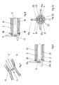
- FIGS. 8 + 9 further embodiments of the endoscope in partial and axially sectioned representation,
- FIG. 10 shows an end view of the representation according to FIG. 9.
Nach den Figuren 1, 2 und 5 besteht das Endoskop 1 im wesentlichen aus einem Außenschaft 2 mit einer darauf verschiebbar angebrachten Anschlagscheibe 3, aus einem Innenschaft 4 sowie aus einer in den Innenschaft 4 einführbaren Optik 5.According to FIGS. 1, 2 and 5, the endoscope 1 essentially consists of an
In einem Ringraum 8 zwischen dem Außenschaft 2 und der Optik 5 ist gemäß den Figuren 2 und 5 eine Mehrzahl von Hakenelementen 6 angeordnet und axial geführt. Die Führung kann durch Längsnuten 7 in der Außenfläche des Innenschaftes 4 erfolgen oder durch einen mit entsprechenden Ausnehmungen versehenen Führungsring. Die Hakenelemente 6 bestehen aus einem längeren, hochelastischen Draht oder Band und weisen im Bereich ihres distalen Endes eine immanente Vorbiegung 9 auf, die sich beim Hinausschieben des Hakenelementes über das distale Ende des Außenschaftes 2 hinaus, wie in Figur 2 gezeigt, in radialer Richtung über den Außenschaft 2 hinaus spreizt und dabei als Hakenteil ausbildet. Um einen traumatischen Effekt sicher zu vermeiden, ist das vorgebogene Ende jedes Hakenelementes 6 an seinem distalen Ende mit einer weiteren, entgegen der genannten Vorbiegung verlaufenden, immanenten Rückbiegung 9a versehen. Die Länge der Hakenelemente 6 ist so gewählt, daß sie vollständig in den Außenschaft 2 des Instrumentes 1 hineingezogen werden können, wodurch vermieden wird, daß beim Einführen des Endoskopes 1 in ein Hohlorgan 10 oder 11 eines Lebewesens eine zusätzliche Traumatisierung durch die Hakenelemente 6 erfolgt. Die Hakenelemente 6 sind gemäß Fig. 4 mit ihrem proximalen Ende an einer in dem Ringraum 8 zwischen dem Außenschaft 2 und der Optik 5 verschiebbaren Hülse 16 festgelegt. Die Hülse 16 ist über eine Verbindungsschraube mit einer Stelleinrichtung 13 in Form einer Schiebehülse im Bereich der Handhabe 12 des Instrumentes 1 verbunden.According to FIGS. 2 and 5, a plurality of
Die Wirkungsweise dieser Ausführungsform des Endoskopes ist folgende:
- Zur Behandlung eines
Hohlorgans 10, z. B. desjenigen nachFigur 6, wird zunächst das Endoskop 1 mit seinemAußenschaft 2 in dieses Hohlorgan eingeführt, wobei dieHakenelemente 6 in denAußenschaft 2 eingezogen sind. Nach dem Einführen wird dieSchiebehülse 13 an derHandhabe 12 des Endoskopes 1 distalwärts vorgeschoben, was bewirkt, daß dieimmamenten Hakenteile 9 über das distale Ende desAußenschaftes 2 hinausgeschoben werden. Dadurch wird die äußere Abstützung derHakenteile 9 fortschreitend aufgehoben, so daß sie sich zunehmend aufspreizen und als Haken ausbilden. Sie erreichen dadurch schließlich die Innenwand desHohlorganes 10, an der sie sich anlegen. In dieser Stellung wird das Endoskop 1mitsamt dem Hohlorgan 10 gegen eine festere Gewebestruktur, z. B. gegen die Bauchdecke 14, bis zur Anlage an dieser zurückgezogen und sodann dieAnschlagscheibe 3 bis an die Außenseite dieser festeren Gewebestruktur herangeschoben und in der Anschlagstellung fixiert.
- For the treatment of a
hollow organ 10, e.g. B. that of Figure 6, the endoscope 1 is first inserted with itsouter shaft 2 in this hollow organ, wherein thehook elements 6 are drawn into theouter shaft 2. After insertion, the slidingsleeve 13 is advanced distally towards thehandle 12 of the endoscope 1, which causes theimmobile hook parts 9 to be pushed beyond the distal end of theouter shaft 2. As a result, the outer support of thehook parts 9 is progressively removed, so that they spread apart and form as hooks. In this way, they finally reach the inner wall of thehollow organ 10, on which they rest. In this position, the endoscope 1 together with thehollow organ 10 against a firmer tissue structure, for. B. against the abdominal wall 14, withdrawn until it abuts against it and then thestop disc 3 is pushed up to the outside of this firmer tissue structure and fixed in the stop position.
Somit ist das Hohlorgan 10 sicher fixiert und kann endoskopisch genau untersucht und behandelt werden.The
Um mit dem Endoskop 1 Messungen in Hohlorganen vornehmen zu können, ist im Bereich der proximalen Handhabe 12 eine Maßeinteilung 15 vorgesehen, auf der das der Entfernung der Enden von sich gegenüberliegenden Hakenteilen 9 entsprechende Maß abgelesen werden kann. Bei röhrenförmigen Hohlorganen 11 (Figur 7) wird das Endoskop 1 mit Hilfe der Kontrolle durch die Optik 5 an den interessierenden Bereich herangebracht und sodann die immanenten Hakenteile 9 aus dem distalen Ende des Außenschaftes 2 herausgeschoben, bis sie die Wand des Hohlorgans 11 berühren. Hierdurch kann z. B. bei pathologischen Veränderungen der noch verbliebene freie Durchgang eines röhrenförmigen Hohlorgans gemessen werden.In order to be able to carry out measurements in hollow organs with the endoscope 1, a
In abgeänderter Ausführungsform nach Figur 8 kann das vorgeschlagene Endoskop hinsichtlich der Hakenelemente auch so ausgebildet sein, daß eine Vielzahl von starren, L-förmigen Hakenelementen 17 in axialen Schlitzen 18 am distalen Ende des Außenschaftes 2 umfangsmäßig verteilt und radial verschwenkbar angelenkt ist, wie es Figur 8 zeigt. Die Anlenkung und die Formgestaltung der Hakenelemente 16 ist dabei so gewählt, daß die Hakenelemente in ihrer Nichtfunktionsstellung in bezug auf den Außenschaft 2 mit Hilfe der Optik 5 nicht radial nach außen vorstehen, wie es in der unteren Hälfte in Figur 8 gezeigt ist. Die obere Hälfte in Figur 8 zeigt die Funktionsstellung der Hakenelemente 17. Die Schwenkbetätigung der Hakenelemente erfolgt durch axiale Vorbewegung des Innenschaftes 19 in dem Außenschaft 2, wobei der auch die Optik 5 aufnehmende Innenschaft zunächst gegen das Knie der L-förmigen Hakenelemente drückt, um diese Elemente radial auszuschwenken, wie aus Figur 7 unten erkennbar ist, und dann die anderen Schenkel der Hakenelemente durch seine vorgeschobene Stellung radial nach außen geschwenkt hält, wie es in Figur 8 oben gezeigt ist.In a modified embodiment according to Figure 8, the proposed endoscope can with regard the hook elements can also be designed such that a plurality of rigid, L-shaped
Bei dem noch weiteren Ausführungsbeispiel nach den Figuren 9 und 10 weist der Innenschaft 21 eine der Anzahl der im Außenschaft 2 mit Kugelgelenken 20 gelagerten Hakenelemente 17a entsprechende Anzahl von Ausnehmungen 22 auf, die dazu dienen, die Hakenelemente 17a in achsparalleler Stellung, wie im unteren Teil der Figur 9 dargestellt, vermittels der Optik 5 zu fixieren.In the still further exemplary embodiment according to FIGS. 9 and 10, the
Zum Ausschwenken der Hakenelemente 17a, z. B. in die Stellung, wie im oberen Teil der Figur 9 dargestellt, werden zunächst die Optik 5 und der Innenschaft 21 soweit proximalwärts zurückgezogen, bis das distale Ende des Innenschaftes 21 vollständig proximalseits des proximalen Endes der Haken 17a liegt. Anschließend wird der Innenschaft 21 so gedreht, daß die Aussparungen 22, wie in Figur 10 dargestellt, nicht mehr in Richtung der Hakenelemente 17a zeigen. Durch Vorschieben des Innenschaftes 21 in Richtung auf die Hakenelemente 17a werden diese durch den Schaft 21 in radialer Richtung ausgeschwenkt.To pivot the
Zum Rückführen der Hakenelemente 17a in die achsparallele Ruhestellung wird der Innenschaft wieder gedreht, bis sich die Positionen der im Außenschaft 2 angelenkten Hakenelemente 17a und die Ausnehmungen 22 des Innenschaftes 21 decken, so daß die Hakenelemente, z. B. beim Herausziehen des Instrumentes aus der Körperhöhle, in die Ruhestellung zurückfallen.To return the
Um beim Einführen des Endoskopes in eine Körperhöhle keine unnötigen Traumatisierungen herbeizuführen, werden die Hakenelemente 17a auch in dieser Ausführungsform in ihrer Ruhelage einfach durch distalwärtiges Vorschieben der Optik 5 fixiert.In order not to cause unnecessary trauma when inserting the endoscope into a body cavity, the
Das erfindungsgemäße Endoskop 1 kann auch als flexibles Instrument mit flexiblen Schäften 2, 4 bzw. 19, 21 anstelle starrer Schäfte und mit einer flexiblen Optik anstelle einer starren Optik 5 ausgebildet sein.The endoscope 1 according to the invention can also be designed as a flexible instrument with
Claims (7)
Applications Claiming Priority (2)
| Application Number | Priority Date | Filing Date | Title |
|---|---|---|---|
| DE4125806A DE4125806A1 (en) | 1991-08-03 | 1991-08-03 | ENDOSCOPE FOR INSERTION INTO A CAVITY ORGAN OF A LIVING BEING |
| DE4125806 | 1991-08-03 |
Publications (1)
| Publication Number | Publication Date |
|---|---|
| EP0526721A1 true EP0526721A1 (en) | 1993-02-10 |
Family
ID=6437667
Family Applications (1)
| Application Number | Title | Priority Date | Filing Date |
|---|---|---|---|
| EP92110439A Withdrawn EP0526721A1 (en) | 1991-08-03 | 1992-06-20 | Endoscope for inserting into a cavity of an organ of a living being |
Country Status (3)
| Country | Link |
|---|---|
| US (1) | US5309894A (en) |
| EP (1) | EP0526721A1 (en) |
| DE (1) | DE4125806A1 (en) |
Cited By (7)
| Publication number | Priority date | Publication date | Assignee | Title |
|---|---|---|---|---|
| US5425357A (en) * | 1991-05-29 | 1995-06-20 | Origin Medsystems, Inc. | Inflatable retraction devices for use in laparoscopic surgery |
| US5505689A (en) * | 1991-05-29 | 1996-04-09 | Origin Medsystems, Inc. | Propertioneal mechanical retraction apparatus |
| US5697946A (en) * | 1994-10-07 | 1997-12-16 | Origin Medsystems, Inc. | Method and apparatus for anchoring laparoscopic instruments |
| GB2320683A (en) * | 1996-12-25 | 1998-07-01 | Asahi Optical Co Ltd | Surgical stripper for use under endoscopic observation |
| FR2770122A1 (en) * | 1997-10-28 | 1999-04-30 | Asahi Optical Co Ltd | ENDOSCOPIC LENGTH MEASUREMENT TOOL |
| WO2008121794A1 (en) * | 2007-03-29 | 2008-10-09 | Frantz Medical Development, Ltd. | Securable cannula and method |
| DE102016004811A1 (en) | 2016-04-20 | 2017-10-26 | Rheinisch-Westfälische Technische Hochschule (Rwth) Aachen | Hollow organ anchoring device |
Families Citing this family (10)
| Publication number | Priority date | Publication date | Assignee | Title |
|---|---|---|---|---|
| DE4125806A1 (en) * | 1991-08-03 | 1993-02-04 | Wolf Gmbh Richard | ENDOSCOPE FOR INSERTION INTO A CAVITY ORGAN OF A LIVING BEING |
| DE4303274C2 (en) * | 1993-02-05 | 1997-02-06 | Wolf Gmbh Richard | Endoscopic instrument |
| SE509389C2 (en) * | 1996-07-24 | 1999-01-18 | Solem Jan Otto | Device for connecting the end of a first blood vessel to the side of a second blood vessel |
| US6056762A (en) * | 1997-05-22 | 2000-05-02 | Kensey Nash Corporation | Anastomosis system and method of use |
| US6063114A (en) * | 1997-09-04 | 2000-05-16 | Kensey Nash Corporation | Connector system for vessels, ducts, lumens or hollow organs and methods of use |
| JP3331172B2 (en) * | 1998-06-12 | 2002-10-07 | 旭光学工業株式会社 | Endoscope foreign matter collection tool |
| US10258368B2 (en) * | 2010-09-14 | 2019-04-16 | Suremka, Llc | Retractable cannula for surgical procedures |
| US11627985B2 (en) * | 2014-06-10 | 2023-04-18 | Suremka, Llc | Surgical devices and deployment apparatuses |
| EP3471594A4 (en) * | 2016-06-18 | 2019-11-13 | Arthroscopic Innovations, LLC | Surgical devices and methods |
| CN110996755B (en) * | 2017-08-17 | 2023-03-03 | 270外科有限公司 | Multi-position medical operation lighting device with variable diameter |
Citations (4)
| Publication number | Priority date | Publication date | Assignee | Title |
|---|---|---|---|---|
| GB1173194A (en) * | 1966-10-03 | 1969-12-03 | American Cystoscope Makers Inc | A Medical Instrument |
| US3717151A (en) * | 1971-03-11 | 1973-02-20 | R Collett | Flesh penetrating apparatus |
| US4016867A (en) * | 1976-04-27 | 1977-04-12 | The United States Of America As Represented By The Secretary Of The Department Of Health, Education And Welfare | Uterine caliper and depth gauge |
| DE8303342U1 (en) * | 1983-07-14 | Storz-Endoskop GmbH, 6207 Schaffhausen | Medical grasping instrument |
Family Cites Families (17)
| Publication number | Priority date | Publication date | Assignee | Title |
|---|---|---|---|---|
| DE640126C (en) * | 1934-07-29 | 1936-12-24 | Bruno Loewel Dr | Trocar |
| US3570498A (en) * | 1970-03-09 | 1971-03-16 | Charles Weighton | Trocar and cannula for veterinary use |
| US3866599A (en) * | 1972-01-21 | 1975-02-18 | Univ Washington | Fiberoptic catheter |
| US4027510A (en) * | 1974-05-15 | 1977-06-07 | Siegfried Hiltebrandt | Forceps |
| US4168709A (en) * | 1975-03-10 | 1979-09-25 | Bentov Itzhak E | Dilator |
| US3994301A (en) * | 1975-04-14 | 1976-11-30 | S & S Medical Products Co., Inc. | Submammary dissector |
| JPS5641684Y2 (en) * | 1977-11-24 | 1981-09-30 | ||
| DE3330921C1 (en) * | 1983-08-27 | 1985-02-07 | Karl-Heinz Dr.med. 4000 Düsseldorf Kurz | Device for determining the internal mass of hollow organs, especially the uterine cavity |
| US4608965A (en) * | 1985-03-27 | 1986-09-02 | Anspach Jr William E | Endoscope retainer and tissue retracting device |
| US4791913A (en) * | 1987-12-14 | 1988-12-20 | Baxter Travenol Laboratories, Inc. | Optical valvulotome |
| US5002560A (en) * | 1989-09-08 | 1991-03-26 | Advanced Cardiovascular Systems, Inc. | Expandable cage catheter with a rotatable guide |
| US5197971A (en) * | 1990-03-02 | 1993-03-30 | Bonutti Peter M | Arthroscopic retractor and method of using the same |
| DE69120325T2 (en) * | 1990-03-29 | 1996-12-12 | United States Surgical Corp | Retractor for abdominal organs |
| DE4021153A1 (en) * | 1990-07-03 | 1992-01-16 | Wolf Gmbh Richard | ORGAN MANIPULATOR |
| US5160341A (en) * | 1990-11-08 | 1992-11-03 | Advanced Surgical Intervention, Inc. | Resorbable urethral stent and apparatus for its insertion |
| US5183033A (en) * | 1991-07-15 | 1993-02-02 | Wilk Peter J | Surgical instrument assembly and apparatus and surgical method |
| DE4125806A1 (en) * | 1991-08-03 | 1993-02-04 | Wolf Gmbh Richard | ENDOSCOPE FOR INSERTION INTO A CAVITY ORGAN OF A LIVING BEING |
-
1991
- 1991-08-03 DE DE4125806A patent/DE4125806A1/en active Granted
-
1992
- 1992-06-20 EP EP92110439A patent/EP0526721A1/en not_active Withdrawn
- 1992-07-31 US US07/923,697 patent/US5309894A/en not_active Expired - Fee Related
Patent Citations (4)
| Publication number | Priority date | Publication date | Assignee | Title |
|---|---|---|---|---|
| DE8303342U1 (en) * | 1983-07-14 | Storz-Endoskop GmbH, 6207 Schaffhausen | Medical grasping instrument | |
| GB1173194A (en) * | 1966-10-03 | 1969-12-03 | American Cystoscope Makers Inc | A Medical Instrument |
| US3717151A (en) * | 1971-03-11 | 1973-02-20 | R Collett | Flesh penetrating apparatus |
| US4016867A (en) * | 1976-04-27 | 1977-04-12 | The United States Of America As Represented By The Secretary Of The Department Of Health, Education And Welfare | Uterine caliper and depth gauge |
Cited By (13)
| Publication number | Priority date | Publication date | Assignee | Title |
|---|---|---|---|---|
| US5505689A (en) * | 1991-05-29 | 1996-04-09 | Origin Medsystems, Inc. | Propertioneal mechanical retraction apparatus |
| US5575759A (en) * | 1991-05-29 | 1996-11-19 | Origin Medsystems, Inc. | Methods of using inflatable retraction devices in laparoscopic surgery |
| US5425357A (en) * | 1991-05-29 | 1995-06-20 | Origin Medsystems, Inc. | Inflatable retraction devices for use in laparoscopic surgery |
| US6524283B1 (en) | 1994-10-07 | 2003-02-25 | Sherwood Services Ag | Method and apparatus for anchoring laparoscopic instruments |
| US5697946A (en) * | 1994-10-07 | 1997-12-16 | Origin Medsystems, Inc. | Method and apparatus for anchoring laparoscopic instruments |
| US7235064B2 (en) | 1994-10-07 | 2007-06-26 | Sherwood Services Ag | Method and apparatus for anchoring laparoscopic instruments |
| GB2320683A (en) * | 1996-12-25 | 1998-07-01 | Asahi Optical Co Ltd | Surgical stripper for use under endoscopic observation |
| US6033359A (en) * | 1997-10-28 | 2000-03-07 | Asahi Kogaku Kogyo Kabushiki Kaisha | Endoscopic length-measuring tool |
| FR2770122A1 (en) * | 1997-10-28 | 1999-04-30 | Asahi Optical Co Ltd | ENDOSCOPIC LENGTH MEASUREMENT TOOL |
| WO2008121794A1 (en) * | 2007-03-29 | 2008-10-09 | Frantz Medical Development, Ltd. | Securable cannula and method |
| US8360969B2 (en) | 2007-03-29 | 2013-01-29 | Frantz Medical Development, Ltd. | Securable cannula and method |
| DE102016004811A1 (en) | 2016-04-20 | 2017-10-26 | Rheinisch-Westfälische Technische Hochschule (Rwth) Aachen | Hollow organ anchoring device |
| WO2017182117A1 (en) | 2016-04-20 | 2017-10-26 | Rheinisch-Westfälische Technische Hochschule (Rwth) Aachen | Hollow organ anchoring device |
Also Published As
| Publication number | Publication date |
|---|---|
| US5309894A (en) | 1994-05-10 |
| DE4125806A1 (en) | 1993-02-04 |
| DE4125806C2 (en) | 1993-06-17 |
Similar Documents
| Publication | Publication Date | Title |
|---|---|---|
| DE4125806C2 (en) | ||
| DE69919343T2 (en) | GUIDE SLEEVE FOR MOVED SPINE BODIES | |
| DE3344934C2 (en) | ||
| DE3709706C2 (en) | ||
| DE2800362C3 (en) | Endoscope with controllably movable guide tube for an instrument | |
| DE69532995T2 (en) | FLEXIBLE SURGICAL INSTRUMENTS THAT HAVE A SPIRAL WITH LUMENS | |
| EP0464463A1 (en) | Organ manipulator | |
| DE2305815A1 (en) | DEVICE FOR SEPARATING SURGICAL FEEDS | |
| EP0605764A1 (en) | Device for implantation and extraction of stents | |
| DE4303274C2 (en) | Endoscopic instrument | |
| DE19540731C2 (en) | Endoscopic instrument | |
| DE2804058A1 (en) | MEDICAL DEVICE FOR THE REMOVAL OF FOREIGN BODIES FROM A BODY CAVITY | |
| DE3926320C2 (en) | Display device for use with an endoscope | |
| EP1052945B1 (en) | Tubular medical instrument | |
| DE2426781C3 (en) | Device for severing the narrowed sphincter muscle at the mouth of the bile duct in the duodenum | |
| EP0613386B1 (en) | Medical probe for insertion in the cavities of the body | |
| DE10027342A1 (en) | Treatment instrument has flexible sleeve for endoscope duct, with protruding distal end, and less rigid proximal end | |
| DE19515626C2 (en) | Instrument for positioning at least one working sleeve | |
| DE3620385C1 (en) | Forceps for the percutaneous removal of renal calculi | |
| DE19629537A1 (en) | Trocar sleeve | |
| EP0999811B1 (en) | Device for expanding and reconstructing the lacrimal duct of a human eye | |
| DE3511448C2 (en) | Ureteral catheter | |
| DE19955614C1 (en) | Endoscopically-inserted falloposcope for examining ovaries and fallopian tubes has longitudinal slits at instrument end of Bowden cable providing expansion arms for widening out fallopian tube | |
| DE10241946A1 (en) | Apparatus for minimally invasive surgical removal of foreign bodies having a tube with a lumen open at the distal end | |
| EP4125541B1 (en) | Endoscopy equipment |
Legal Events
| Date | Code | Title | Description |
|---|---|---|---|
| PUAI | Public reference made under article 153(3) epc to a published international application that has entered the european phase |
Free format text: ORIGINAL CODE: 0009012 |
|
| AK | Designated contracting states |
Kind code of ref document: A1 Designated state(s): BE CH DE FR GB LI |
|
| 17P | Request for examination filed |
Effective date: 19930724 |
|
| 17Q | First examination report despatched |
Effective date: 19950317 |
|
| STAA | Information on the status of an ep patent application or granted ep patent |
Free format text: STATUS: THE APPLICATION HAS BEEN WITHDRAWN |
|
| 18W | Application withdrawn |
Withdrawal date: 19951209 |