EP0528606A2 - Thermally conductive interface materials - Google Patents
Thermally conductive interface materials Download PDFInfo
- Publication number
- EP0528606A2 EP0528606A2 EP92307262A EP92307262A EP0528606A2 EP 0528606 A2 EP0528606 A2 EP 0528606A2 EP 92307262 A EP92307262 A EP 92307262A EP 92307262 A EP92307262 A EP 92307262A EP 0528606 A2 EP0528606 A2 EP 0528606A2
- Authority
- EP
- European Patent Office
- Prior art keywords
- thermally conductive
- thermal energy
- heat
- air
- conductive material
- Prior art date
- Legal status (The legal status is an assumption and is not a legal conclusion. Google has not performed a legal analysis and makes no representation as to the accuracy of the status listed.)
- Withdrawn
Links
Images

Classifications
-
- H—ELECTRICITY
- H05—ELECTRIC TECHNIQUES NOT OTHERWISE PROVIDED FOR
- H05K—PRINTED CIRCUITS; CASINGS OR CONSTRUCTIONAL DETAILS OF ELECTRIC APPARATUS; MANUFACTURE OF ASSEMBLAGES OF ELECTRICAL COMPONENTS
- H05K7/00—Constructional details common to different types of electric apparatus
- H05K7/20—Modifications to facilitate cooling, ventilating, or heating
-
- H—ELECTRICITY
- H01—ELECTRIC ELEMENTS
- H01L—SEMICONDUCTOR DEVICES NOT COVERED BY CLASS H10
- H01L23/00—Details of semiconductor or other solid state devices
- H01L23/34—Arrangements for cooling, heating, ventilating or temperature compensation ; Temperature sensing arrangements
- H01L23/36—Selection of materials, or shaping, to facilitate cooling or heating, e.g. heatsinks
- H01L23/373—Cooling facilitated by selection of materials for the device or materials for thermal expansion adaptation, e.g. carbon
- H01L23/3737—Organic materials with or without a thermoconductive filler
-
- H—ELECTRICITY
- H01—ELECTRIC ELEMENTS
- H01L—SEMICONDUCTOR DEVICES NOT COVERED BY CLASS H10
- H01L23/00—Details of semiconductor or other solid state devices
- H01L23/34—Arrangements for cooling, heating, ventilating or temperature compensation ; Temperature sensing arrangements
- H01L23/36—Selection of materials, or shaping, to facilitate cooling or heating, e.g. heatsinks
- H01L23/367—Cooling facilitated by shape of device
-
- H—ELECTRICITY
- H01—ELECTRIC ELEMENTS
- H01L—SEMICONDUCTOR DEVICES NOT COVERED BY CLASS H10
- H01L23/00—Details of semiconductor or other solid state devices
- H01L23/34—Arrangements for cooling, heating, ventilating or temperature compensation ; Temperature sensing arrangements
- H01L23/36—Selection of materials, or shaping, to facilitate cooling or heating, e.g. heatsinks
- H01L23/373—Cooling facilitated by selection of materials for the device or materials for thermal expansion adaptation, e.g. carbon
- H01L23/3733—Cooling facilitated by selection of materials for the device or materials for thermal expansion adaptation, e.g. carbon having a heterogeneous or anisotropic structure, e.g. powder or fibres in a matrix, wire mesh, porous structures
-
- H—ELECTRICITY
- H01—ELECTRIC ELEMENTS
- H01L—SEMICONDUCTOR DEVICES NOT COVERED BY CLASS H10
- H01L2924/00—Indexing scheme for arrangements or methods for connecting or disconnecting semiconductor or solid-state bodies as covered by H01L24/00
- H01L2924/0001—Technical content checked by a classifier
- H01L2924/0002—Not covered by any one of groups H01L24/00, H01L24/00 and H01L2224/00
-
- Y—GENERAL TAGGING OF NEW TECHNOLOGICAL DEVELOPMENTS; GENERAL TAGGING OF CROSS-SECTIONAL TECHNOLOGIES SPANNING OVER SEVERAL SECTIONS OF THE IPC; TECHNICAL SUBJECTS COVERED BY FORMER USPC CROSS-REFERENCE ART COLLECTIONS [XRACs] AND DIGESTS
- Y10—TECHNICAL SUBJECTS COVERED BY FORMER USPC
- Y10T—TECHNICAL SUBJECTS COVERED BY FORMER US CLASSIFICATION
- Y10T428/00—Stock material or miscellaneous articles
- Y10T428/24—Structurally defined web or sheet [e.g., overall dimension, etc.]
- Y10T428/24273—Structurally defined web or sheet [e.g., overall dimension, etc.] including aperture
-
- Y—GENERAL TAGGING OF NEW TECHNOLOGICAL DEVELOPMENTS; GENERAL TAGGING OF CROSS-SECTIONAL TECHNOLOGIES SPANNING OVER SEVERAL SECTIONS OF THE IPC; TECHNICAL SUBJECTS COVERED BY FORMER USPC CROSS-REFERENCE ART COLLECTIONS [XRACs] AND DIGESTS
- Y10—TECHNICAL SUBJECTS COVERED BY FORMER USPC
- Y10T—TECHNICAL SUBJECTS COVERED BY FORMER US CLASSIFICATION
- Y10T428/00—Stock material or miscellaneous articles
- Y10T428/24—Structurally defined web or sheet [e.g., overall dimension, etc.]
- Y10T428/24479—Structurally defined web or sheet [e.g., overall dimension, etc.] including variation in thickness
- Y10T428/2457—Parallel ribs and/or grooves
- Y10T428/24579—Parallel ribs and/or grooves with particulate matter
-
- Y—GENERAL TAGGING OF NEW TECHNOLOGICAL DEVELOPMENTS; GENERAL TAGGING OF CROSS-SECTIONAL TECHNOLOGIES SPANNING OVER SEVERAL SECTIONS OF THE IPC; TECHNICAL SUBJECTS COVERED BY FORMER USPC CROSS-REFERENCE ART COLLECTIONS [XRACs] AND DIGESTS
- Y10—TECHNICAL SUBJECTS COVERED BY FORMER USPC
- Y10T—TECHNICAL SUBJECTS COVERED BY FORMER US CLASSIFICATION
- Y10T428/00—Stock material or miscellaneous articles
- Y10T428/28—Web or sheet containing structurally defined element or component and having an adhesive outermost layer
- Y10T428/2848—Three or more layers
Definitions
- the present invention relates to a thermally conductive interface material, an apparatus and a method for applying the same to a heat source and a heat sink. More particularly, the present invention relates to a thermally conductive material, an apparatus and a method for applying the same which eliminates the formation of air pockets between the thermally conductive material and the substrates to which it is bonded.
- the present invention relates to a thermally conductive interface material that is interposed between a source of heat, such as an electronic component and a heat sink.
- a source of heat such as an electronic component
- the most common example of this invention is the use of a thermal material between a semiconductor device and a heat sink so that heat generated by the semiconductor can be removed.
- thermally conductive materials typically, silicone or urethane binders filled with one or more thermally conductive materials are used as the thermal interface.
- One such product is commercially known as CHO-THERM® thermally conductive materials, available from Chomerics, Inc.
- thermally conductive interface materials are applied individually by hand. This is a labor extensive, slow process. Additionally, the assembly can only be done with fairly large components which contain a measn for attaching them to the heat source, such as screws, rivets, etc.
- the present invention provides a thermally conductive material which contains a means for eliminating air from between the surface of the thermally conductive material and the substrate to which it is joined.
- the means for eliminating the air consists of a series of grooves or channels or a series of throughholes in one or both major surfaces of the thermally conductive material and/or the heat sink or heat souce so that as pressure is applied between the thermally conductive material and the adjacent heat sink or heat source, any air is expelled through the grooves, channels or throughholes.
- the thermally conductive material has a polymeric binder that is a pressure sensitive adhesive, such as an acrylic or silicone pressure sensitive adhesive.
- the pressure sensitive thermally conductive material allows for bonding directly to the adjacent surfaces of the heat source and heat sink without the need for other retaining means such as screws, rivets, clamps, etc. It also allows for the use of thermal interface materials on electronic components which previously could not retain such materials, due to size, configuration, etc. Moreover, it allows for the automated application and assembly of thermally conductive electronic assemblies or packages. It is an object of the present invention to provide thermally conductive materials comprising a blend of a polymeric binder and a thermally conductive filler wherein the material has an air removing device selected from the group consisting of embossments and throughholes.
- a further object of the present invention is to provide a thermally conductive, form stable sheet formed of a blend of a polymeric binder selected from the group consisting of acrylic resin silicone rubber, fluorosilicone rubber and polyurethane, a thermally conductive filler and wherein at least one major surface of the material contains embossments for the removal air upon the application of pressure to the material.
- Another object of the present invention is to provide a means for dissipating heat comprising a thermally conductive material having a major surface for mounting a heat generating means and one or more means for dissipating heat from the heat generating means to the atmosphere, wherein the major surface has a means for removing air from between the heat generating means.
- An additional object of the present invention is to provide an electrical assembly comprising a means for dissipating thermal energy, an electronic component which generates thermal energy and a means for transferring thermal energy from the electronic component to the means for dissipating thermal energy and the electronic component and wherein at least the means for transferring thermal energy has a means for removing air from between the measn for transferring themral energy and the electronic components.
- a further object of the present invention is to provide a process for assembling a thermally conductive electrical assembly comprising the steps of mounting a first surface of a means for transferring thermal energy to a means for disspating thermal energy, mounting a second surface of the means for transferring thermal energy to a means for generating thermal energy, wherein at least the second surface of the means for transferring thermal energy has a means for removing air from between the means for transferring thermal energy and the means for generating thermal energy when subjected to pressure and applying pressure to assembly to remove air from the assembly.
- Another object of the present invention is to provide a thermally conductive interface comprised of a pressure sensitive adhesive polymeric binder and one or more thermally conductive fillers wherein the interface has a series of air removing devices formed in at least one surface of the interface.
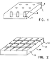
- Figure 1 shows a plan as view of first preferred embodiment of the thermally conductive material of the present invention.
- Figure 2 shows a planar view of another preferred embodiment of the thermally conductive material of the present invention.
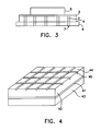
- Figure 3 shows a cross sectional view of a preferred embodiment of an assembly according to the present invention.
- Figure 4 shows a planar view of another preferred embodiment of the thermally conductive material of the present invention.
- Figure 5 shows a cross sectional view of a preferred apparatus for forming the assembly.
- a preferred embodiment of the present invention comprises a form stable, sheet like thermally conductive material formed of a polymeric binder, one or more thermally conductive fillers and a means for removing air from between a major surface of the material and a substrate to which the major surface is mated.
- a form stable, sheet like thermally conductive material formed of a polymeric binder, one or more thermally conductive fillers and a means for removing air from between a major surface of the material and a substrate to which the major surface is mated.
- the thermally conductive material 1 has a series of throughholes 2 running from one major surface 3 to a second, opposite major surface 4.
- the thermally conductive material is interposed between a heat source and a heat dissipator.
- the first major surface 3 of the material is adjacent to the heat source and the second major surface 4 is adjacent to heat dissipator.
- Figure 3 shows the embodiment of Figure 1 as assembled between the heat source 5 and heat dissipator 6.
- the heat dissipator also has throughholes 7 which are arranged in such a manner so as to be in alignment, register or correspondence with the throughholes of the thermally conductive material.
- the size (diameter), arrangement and number of throughholes should be sufficient to allow for the removal of substantially all of the air between the thermal material and the adjacent substrate to which it is mated yet insufficient so as to structurally weaken the material or to substantially reduce its thermal properties.
- the throughholes are circular in shape, however, other shapes, such as square, rectangular, oval etc. may be used if desired.
- Figure 2 shows an alternative embodiment of the thermally conductive material 11 wherein one of its major surfaces, in this instance its first major surface 13, has a series of grooves or channels formed in it which form a series of embossments or lands on the surface of the material.
- the channels act as the air removal device, 12.
- the second major surface, 14, may contain the air removal device instead of or in addition to the first major surface 13.
- the grooves or channels may be linear, or curvilinear or any other configuration. If desired they may run only in one direction across the surface of the material, such as parallel stripes or they may run in two different directions at an angle to each other as shown in Figure 2. Preferably, there are two series of grooves running perpendicular to each other.
- Another preferred embodiment of the present invention is an assembly of a thermal energy generating means, such as an electronic component, a thermal energy dissipating means, such as a heat sink or a heat spreader, and a thermal energy transferring means such as a thermally conductive polymeric material interposed between the generating means and the dissipating means so as to move the thermal energy from the generating means to the dissipating means.
- a thermal energy generating means such as an electronic component
- a thermal energy dissipating means such as a heat sink or a heat spreader
- a thermal energy transferring means such as a thermally conductive polymeric material interposed between the generating means and the dissipating means so as to move the thermal energy from the generating means to the dissipating means.
- Either the transferring means and/or the heat dissipating means contains a means for removing air from between the heat transferring means and an adjacent surface of either the heat generating means and/or the heat dissipating means
- both the heat transferring means and the heat dissipating means contain a series of throughholes which correspond to and align or are in register with the throughholes of the other.
- the thermal energy transferring means has no air removal means. Rather the air removal means is formed on the heat dissipating means and/or the heat generating means.
- a heat sink may have the surface, to which the thermally conductive pad will be mounted, grooved or cross hatched so as to form a series of channels through which air can be expelled as the thermal transfer means is applied to surface and fills the grooves or channels. It would be similar in configuration to the embodiment of the thermal material of Figure 2.
- the surface of the electronic component may contain such channels.
- the heat sink may use throughholes.
- Other arrangements in the assembly are possible so as to maximize the thermal capabilities of the assembly while allowing for maximum flexibility of the assembly design. For example, one could have air removal means on the surface of the thermally conductive material adjacent the electronic component and a similar means on the heat sink, etc.
- the thermally conductive material may be selected from a variety of well-known polymer binders, such as acrylic resin, silicone and fluorosilicone rubber, and various polyurethanes filled with one or more thermally conductive fillers.
- polymer binders such as acrylic resin, silicone and fluorosilicone rubber, and various polyurethanes filled with one or more thermally conductive fillers.
- Such materials formed of silicone or urethan are taught in U.S. Patents 4,574,879 and U.S. 4,869,954 which are incorporated herein by reference in their entirities.
- the thermally conductive material is formed of a polymeric binder of a pressure sensitive adhesive material, such as silicone or an acrylic adhesive and one or more thermally conductive fillers.
- a pressure sensitive adhesive material such as silicone or an acrylic adhesive
- thermally conductive fillers are well-known and commercially available.
- the preferred embodiment is a pressure sensitive acrylic adhesive, which are well-known and commercially available.
- Thermally conductive fillers suitable for use in the present invention are particulate solids capable of providing the material with the desired thermal conductivity.
- these fillers are particulate solids which are electrically insulative as well as thermally conductive.
- the fillers may include various thermally conductive metals such as silver, gold and copper or metal coated materials, such as silver coated glass, silver coated copper or silver coated aluminum.
- the particles should be of a sufficiently small size as to not distort the surface of the thermally conductive material.
- the filler will be of a size from about 1 micron to about 50 microns, more preferably in a range of from about 5 microns to about 25 microns, most preferably about 10 microns.
- the fillers are to be included in the binder in an amount sufficient to provide the desired thermoconductivity.
- the fillers are included in amount of from about 10% by weight to about 85% by weight of the finished product. More preferably, the fillers are included in amounts ranging from about 40% by weight to about 75% by weight and most preferably about 68% by weight.
- the more preferred fillers are boron nitride, mangesium oxide and aluminum oxide with boron nitride being the most preferred filler.
- Additional ingredients may also be added so long as they do not interfere with the conformability or thermal conductivity of the product.
- a solvent when compounding the binder so as to make the mixing and application easier.
- one may also add a pigment, flame retardant, and/or antioxidant to the binder.
- the thermally conductive material of the present invention is form stable, it may be used by itself as a thermal transfer device without the incorporation of a support layer.
- the incorporation of support materials is particularly desired where the problems of cut-through or overtorqued fastners may occur. Cut-through is caused by burrs or sharp metal protusions on one or both of the surfaces to be thermally connected. These burrs or protrusions are believed to cut or tear the thermally conductive material and provide a pathway through which an electrical short may occur.
- overtorquing of the fastening devices is believed to subject the thermally conductive material to abnormally strong tensions which may also cause tearing and electrical shorts.
- any tearing or penetration of the thermally conductive material allows for the formation of a pocket of air, which as described above is a poor thermal conductor. These air prockets can lead to localized hot spots and an overall decline in thermal performance.
- the support material should not interfere with the thermal conductivity of the thermally conductive material.
- the support material is itself thermally conductive.
- the selected support material should be dielectric.
- reinforcing materials useful in the present invention include, but are not limited, to glass fiber, mesh or cloth, plastic fiber, mesh cloth or films and metal fiber, mesh, cloth or foils.
- the glass cloth may be woven or unwoven.
- the plastic support material is preferably a mesh material, or a film. If a film, it may be solid or foraminous.
- suitable plastics include nylons, polyesters, polyamides, polyimides, polyethylenes, or PEEK.
- Well-known plastic films particularly useful in the present invention are MYLAR® polyester films and KAPTON® polyimide films.
- MYLAR® polyester films As plastic films generally exhibit poor thermal conductivity properties, it is desirable to use a film which contains a thermally conductive filler.
- One such filler film is KAPTON MT®, a polyimide film which contains either an aluminum oxide or boron nitride filler. This material exhibits twice the thermal conductivity of an equivalent unfilled film. Alternatively, one may use a very thin film layer so as to minimize its effects on the thermal transfer.
- metal mesh cloths or foil are the preferred support material due to their high thermal conductivity.
- preferred metals useful as a mesh cloth or a foil include but are not limited to, aluminum, copper, silver, iron and tinned copper. Regardless of the support material used, it should be as thin as practicable while still providing the desired support.
- the support materials may be embedded in the thermally conductive material or coated, calendered or attached to one surface of the thermally conductive material.
- the support material and thermally conductive material are formed into a laminate of three or more layers with the support layer being the center layer and the thermally conductive material forming the outer layers.
- the three layered material with the support layer in the middle is the preferred embodiment of the present invention.
- One such embodiment is shown in Figure 4.
- the thermally conductive material has a central support layer 41 and two outer layers of thermally conductive pressure sensitive polymer, 42 and 43, each bonded respectively to a major surface of the central support layer. At least one major surface, such as 44, has a series of air removing devices formed in its surface. In this instance, the use of a series of grooves or channels 45 to form embossments is shown.
- the pressure sensitive material may be formed as a continuous tape, a tape containing discrete parts or as individual pads or pieces.
- the heat conductive material of the present invention may be formed in many ways.
- One method of forming the material is to combine the acrylic binder with the selected filler or fillers and thoroughly mix the ingredients while slowly adding a solvent until a liquid having a smooth texture is achieved. The material is then cast onto a release sheet such as a piece of glass, Mylar® film or coated paper, or on to a support layer and heated to drive off the solvent and form the thermally conductive material.
- a release sheet such as a piece of glass, Mylar® film or coated paper
- An alternative method is to thoroughly mix the ingredients together with a sufficient amount of solvent to obtain a thin liquid.
- the liquid can then be sprayed or coated onto a surface such as a release sheet or a reinforcing material such as a glass fiber cloth, a Kapton® film or metal foil and heated to cure.
- the same liquid formulation may have a porous support material, such as a glass fiber mesh, dipped into it to form the desired coating.
- Another method of forming the heat conductive material of the present invention is by molding. This is particularly useful when one wishes to form a substantially thick heat conductive layer or when one wishes to form a specifically shaped heat conductive material.
- the components are mixed with a solvent and poured into a prefabricated mold which contains the desired embossments, channels or grooves or throughholes.
- a prefabricated mold which contains the desired embossments, channels or grooves or throughholes.
- the mold is then heated or otherwise sujected to an external energy field to form the molded shape.
- a preferred method is to form a laminated pressure sensitive adhesive material of three or more layers in which the center layer is formed of a support layer discussed above, such as glass mesh, KAPTON® film or metal foil and an outer layer of the thermally conductive material is coated on each side of the support layer to form a cohesive laminated material.
- the coating may occur sequentially so that one side of the support layer is coated and cured and then the process is repeated on the opposite side.
- the coating is applied to both sides simulataneously.
- the outer surfaces are covered by a release layer such as a coated paper, foil or a plastic film.
- the thermal conductive layers then have their air removal means formed.
- embossments or grooves or channels are desired, they are preferably formed by passing the material through a pair of rollers, at least one of which has the desired embossment or groove configuration formed upon it. The embossments or grooves are then transferred to the tape.
- the throughholes may be formed by a punch or similar means for forming holes.
- the thermally conductive product may be formed into continuous or discontinuous tapes; or sheets and then cut to the desired shape; or molded in the desired shape at the outset, either in a mold or directly in place, as described above.
- the resultant thermally conductive material should be sufficiently soft so as to conform to the surfaces with which it interfaces.
- the material should have a Shore A harness of less than 100, more preferably, a Shore A hardness of about 70.
- the properties exhibited by a typical product prepared in accordance with the present invention are as follows: Thickness-1 to 20 mils ⁇ 1 mil, preferably about 5-8. Volume Resistivity-1X10¹⁰ohm-cm (ASTM D-257) Dielectric Strength-6000 Volts minimum (ASTMD-149). Hardness, Shore A-70 to 100 (ASTM D-2240) Thermal Impedence-0.09° to 0.40°C./W (Chomerics No. 27). Thermal Conductivity-1.2 X 10- to 1.6 X 10- CAL/°cm sec. (Chomerics No. 28).
- thermally conductive assembly Several processes for forming the thermally conductive assembly can be used.
- the assembly is then subjected to pressure, such as between one's fingers, to evacuate the air through the air removal means of the heat source, transfer means and/or dissipating means.
- FIG. 4 Another preferred process for assembling a thermally conductive electronic assembly is shown in Figure 4 and is particularly useful with the acrylic based, pressure sensitive tape that is preferred in this invention.
- the heat source, 31, such as a semiconductor is placed against a holding means 32, a thermally energy transfer means 33 has a first major surface placed upon and bonded to an exposed surface 34 of the heat source and a thermal energy dissipating means 35, in this instance a heat sink is placed upon and bonded to a second major surface of the transfer means, an assembly holder 36 is used to maintain the assembly in position and pressure is applied by the holder through a pressure means 37 to move the various components together and to evacuate the air between the various surfaces of the components through an air removal device formed on one or both surfaces of the transfer means 33, and/or the heat source 31, and/or the dissipating means 35.
- the assembly may then be removed from the holder.
- the transfer means is not adhesive, other means holding the components together, such as clamps, screws, rivets, etc. may be applied while
- the pressure applied may be positive or negative (i.e. a vacuum). It is preferred to use a positive pressure.
- the amount of pressure, positive or negative, that is applied should be sufficient to remove substantially all of the air present between the adjacent surfaces, yet insufficient to damage any of the components, especially the electronic component.
- the thermal transfer means is in the form of continuous tape, either containing a continuously formed thermal material that is cut to length or if desired containing a series of discrete, individual, pressure sensitive pads or pieces.
- the air removal device whether it is embossments, channels or grooves should be of a height and width sufficient to allow for the removal of air but insufficient so as to allow for the return of air after the interface has been applied to a surface.
- the air removal device in these instances is about 1 to 10 mils in height or depth, as the case may be.
Abstract
Description
- The present invention relates to a thermally conductive interface material, an apparatus and a method for applying the same to a heat source and a heat sink. More particularly, the present invention relates to a thermally conductive material, an apparatus and a method for applying the same which eliminates the formation of air pockets between the thermally conductive material and the substrates to which it is bonded.
- The present invention relates to a thermally conductive interface material that is interposed between a source of heat, such as an electronic component and a heat sink. The most common example of this invention is the use of a thermal material between a semiconductor device and a heat sink so that heat generated by the semiconductor can be removed.
- Typically, silicone or urethane binders filled with one or more thermally conductive materials are used as the thermal interface. One such product is commercially known as CHO-THERM® thermally conductive materials, available from Chomerics, Inc.
- In placing the thermally conductive material between the heatsource and the heatsink, care must be taken to ensure that no air becomes trapped between the thermally conductive material and the adjacent substrate. Air is a notoriously poor conductor of heat and its presence reduces the ability of the thermally conductive material to transport heat from its source to its sink. This can lead to an overheating of the heat source. Moreover, the overheating will be localized at the spot where the air is trapped, causing the overheating to be concentrated in a small area making it more intense and its effects more devastating, especially to electronic components.
- Moreover to ensure that air is not trapped, such thermally conductive interface materials are applied individually by hand. This is a labor extensive, slow process. Additionally, the assembly can only be done with fairly large components which contain a measn for attaching them to the heat source, such as screws, rivets, etc.
- Therefore, there is a need for a thermally conductive material that will eliminate the problem of air becoming trapped between the thermal material and the adjacent substrate and a method for forming a heat transferring assembly.
- Moreover, there is a need for a process that will speed up the assembly of thermally conductive electroinc packages and for products that will provide thermal conductivity to smaller electronic assemblies.
- The present invention provides a thermally conductive material which contains a means for eliminating air from between the surface of the thermally conductive material and the substrate to which it is joined. The means for eliminating the air consists of a series of grooves or channels or a series of throughholes in one or both major surfaces of the thermally conductive material and/or the heat sink or heat souce so that as pressure is applied between the thermally conductive material and the adjacent heat sink or heat source, any air is expelled through the grooves, channels or throughholes.
- Preferably, the thermally conductive material has a polymeric binder that is a pressure sensitive adhesive, such as an acrylic or silicone pressure sensitive adhesive. The pressure sensitive thermally conductive material allows for bonding directly to the adjacent surfaces of the heat source and heat sink without the need for other retaining means such as screws, rivets, clamps, etc. It also allows for the use of thermal interface materials on electronic components which previously could not retain such materials, due to size, configuration, etc. Moreover, it allows for the automated application and assembly of thermally conductive electronic assemblies or packages. It is an object of the present invention to provide thermally conductive materials comprising a blend of a polymeric binder and a thermally conductive filler wherein the material has an air removing device selected from the group consisting of embossments and throughholes.
- A further object of the present invention is to provide a thermally conductive, form stable sheet formed of a blend of a polymeric binder selected from the group consisting of acrylic resin silicone rubber, fluorosilicone rubber and polyurethane, a thermally conductive filler and wherein at least one major surface of the material contains embossments for the removal air upon the application of pressure to the material.
- Another object of the present invention is to provide a means for dissipating heat comprising a thermally conductive material having a major surface for mounting a heat generating means and one or more means for dissipating heat from the heat generating means to the atmosphere, wherein the major surface has a means for removing air from between the heat generating means.
- An additional object of the present invention is to provide an electrical assembly comprising a means for dissipating thermal energy, an electronic component which generates thermal energy and a means for transferring thermal energy from the electronic component to the means for dissipating thermal energy and the electronic component and wherein at least the means for transferring thermal energy has a means for removing air from between the measn for transferring themral energy and the electronic components.
- A further object of the present invention is to provide a process for assembling a thermally conductive electrical assembly comprising the steps of mounting a first surface of a means for transferring thermal energy to a means for disspating thermal energy, mounting a second surface of the means for transferring thermal energy to a means for generating thermal energy, wherein at least the second surface of the means for transferring thermal energy has a means for removing air from between the means for transferring thermal energy and the means for generating thermal energy when subjected to pressure and applying pressure to assembly to remove air from the assembly.
- Another object of the present invention is to provide a thermally conductive interface comprised of a pressure sensitive adhesive polymeric binder and one or more thermally conductive fillers wherein the interface has a series of air removing devices formed in at least one surface of the interface.
- Figure 1 shows a plan as view of first preferred embodiment of the thermally conductive material of the present invention.
- Figure 2 shows a planar view of another preferred embodiment of the thermally conductive material of the present invention.
- Figure 3 shows a cross sectional view of a preferred embodiment of an assembly according to the present invention.
- Figure 4 shows a planar view of another preferred embodiment of the thermally conductive material of the present invention.
- Figure 5 shows a cross sectional view of a preferred apparatus for forming the assembly.
- A preferred embodiment of the present invention comprises a form stable, sheet like thermally conductive material formed of a polymeric binder, one or more thermally conductive fillers and a means for removing air from between a major surface of the material and a substrate to which the major surface is mated. Such a device is shown in Figures 1 and 2.
- In Figure 1, the thermally conductive material 1 has a series of
throughholes 2 running from onemajor surface 3 to a second, opposite major surface 4. In use, the thermally conductive material is interposed between a heat source and a heat dissipator. The firstmajor surface 3 of the material is adjacent to the heat source and the second major surface 4 is adjacent to heat dissipator. Figure 3 shows the embodiment of Figure 1 as assembled between the heat source 5 andheat dissipator 6. Also shown in Figure 3 is the preferred embodiment in which the heat dissipator also has throughholes 7 which are arranged in such a manner so as to be in alignment, register or correspondence with the throughholes of the thermally conductive material. - The size (diameter), arrangement and number of throughholes should be sufficient to allow for the removal of substantially all of the air between the thermal material and the adjacent substrate to which it is mated yet insufficient so as to structurally weaken the material or to substantially reduce its thermal properties. Preferably, the throughholes are circular in shape, however, other shapes, such as square, rectangular, oval etc. may be used if desired.
- Figure 2 shows an alternative embodiment of the thermally
conductive material 11 wherein one of its major surfaces, in this instance its firstmajor surface 13, has a series of grooves or channels formed in it which form a series of embossments or lands on the surface of the material. The channels act as the air removal device, 12. If desired, the second major surface, 14, may contain the air removal device instead of or in addition to the firstmajor surface 13. The grooves or channels may be linear, or curvilinear or any other configuration. If desired they may run only in one direction across the surface of the material, such as parallel stripes or they may run in two different directions at an angle to each other as shown in Figure 2. Preferably, there are two series of grooves running perpendicular to each other. - Another preferred embodiment of the present invention is an assembly of a thermal energy generating means, such as an electronic component, a thermal energy dissipating means, such as a heat sink or a heat spreader, and a thermal energy transferring means such as a thermally conductive polymeric material interposed between the generating means and the dissipating means so as to move the thermal energy from the generating means to the dissipating means. Either the transferring means and/or the heat dissipating means contains a means for removing air from between the heat transferring means and an adjacent surface of either the heat generating means and/or the heat dissipating means. The means for removing air is either the embossments or the throughholes described above in regard to the other preferred embodiments of Figures 1 and 2.
- In an assembly which uses throughholes as the air removal means, such as is shown in Figure 3, it is preferred that both the heat transferring means and the heat dissipating means contain a series of throughholes which correspond to and align or are in register with the throughholes of the other. By having throughholes which extend through the entirety of the thermal energy transferring and thermal energy dissipating means, one is able to ensure that air is removed from between the interface formed by the thermal energy generating means and the transferring means and the interface formed between the transferring means and the thermal energy dissipating means.
- In another preferred assembly embodiment, the thermal energy transferring means has no air removal means. Rather the air removal means is formed on the heat dissipating means and/or the heat generating means. For example, a heat sink may have the surface, to which the thermally conductive pad will be mounted, grooved or cross hatched so as to form a series of channels through which air can be expelled as the thermal transfer means is applied to surface and fills the grooves or channels. It would be similar in configuration to the embodiment of the thermal material of Figure 2. Likewise, the surface of the electronic component may contain such channels. Alternatively, the heat sink may use throughholes. Other arrangements in the assembly are possible so as to maximize the thermal capabilities of the assembly while allowing for maximum flexibility of the assembly design. For example, one could have air removal means on the surface of the thermally conductive material adjacent the electronic component and a similar means on the heat sink, etc.
- The thermally conductive material may be selected from a variety of well-known polymer binders, such as acrylic resin, silicone and fluorosilicone rubber, and various polyurethanes filled with one or more thermally conductive fillers. Such materials formed of silicone or urethan are taught in U.S. Patents 4,574,879 and U.S. 4,869,954 which are incorporated herein by reference in their entirities.
- Preferably, the thermally conductive material is formed of a polymeric binder of a pressure sensitive adhesive material, such as silicone or an acrylic adhesive and one or more thermally conductive fillers. Such polymeric binders are well-known and commercially available. The preferred embodiment is a pressure sensitive acrylic adhesive, which are well-known and commercially available. Thermally conductive fillers suitable for use in the present invention are particulate solids capable of providing the material with the desired thermal conductivity. Preferably, these fillers are particulate solids which are electrically insulative as well as thermally conductive.
- Examples of such particles include but are not limited to aluminum oride, aluminum nitride, boron nitride, magnesium oride and zinc oride. If the material does not need to be electrically insulative, the fillers may include various thermally conductive metals such as silver, gold and copper or metal coated materials, such as silver coated glass, silver coated copper or silver coated aluminum.
- The particles should be of a sufficiently small size as to not distort the surface of the thermally conductive material. Preferably the filler will be of a size from about 1 micron to about 50 microns, more preferably in a range of from about 5 microns to about 25 microns, most preferably about 10 microns. The fillers are to be included in the binder in an amount sufficient to provide the desired thermoconductivity. Preferably, the fillers are included in amount of from about 10% by weight to about 85% by weight of the finished product. More preferably, the fillers are included in amounts ranging from about 40% by weight to about 75% by weight and most preferably about 68% by weight. The more preferred fillers are boron nitride, mangesium oxide and aluminum oxide with boron nitride being the most preferred filler.
- Additional ingredients may also be added so long as they do not interfere with the conformability or thermal conductivity of the product. For example, it is preferred to use a solvent when compounding the binder so as to make the mixing and application easier. If desired, one may also add a pigment, flame retardant, and/or antioxidant to the binder. As the thermally conductive material of the present invention is form stable, it may be used by itself as a thermal transfer device without the incorporation of a support layer.
- If desired, one may incorporate one or more layers of a support material to increase the thermally conductive material's toughness, resistance to elongation and tearing and other mistreatment. The incorporation of support materials is particularly desired where the problems of cut-through or overtorqued fastners may occur. Cut-through is caused by burrs or sharp metal protusions on one or both of the surfaces to be thermally connected. These burrs or protrusions are believed to cut or tear the thermally conductive material and provide a pathway through which an electrical short may occur. Similarly, overtorquing of the fastening devices is believed to subject the thermally conductive material to abnormally strong tensions which may also cause tearing and electrical shorts. Additionally, any tearing or penetration of the thermally conductive material allows for the formation of a pocket of air, which as described above is a poor thermal conductor. These air prockets can lead to localized hot spots and an overall decline in thermal performance.
- The support material should not interfere with the thermal conductivity of the thermally conductive material. Preferably, the support material is itself thermally conductive. In applications where electrical insulation between the components is important, the selected support material should be dielectric.
- Examples of reinforcing materials useful in the present invention include, but are not limited, to glass fiber, mesh or cloth, plastic fiber, mesh cloth or films and metal fiber, mesh, cloth or foils.
- The glass cloth may be woven or unwoven.
- The plastic support material is preferably a mesh material, or a film. If a film, it may be solid or foraminous. Examples of suitable plastics include nylons, polyesters, polyamides, polyimides, polyethylenes, or PEEK. Well-known plastic films particularly useful in the present invention are MYLAR® polyester films and KAPTON® polyimide films. As plastic films generally exhibit poor thermal conductivity properties, it is desirable to use a film which contains a thermally conductive filler. One such filler film is KAPTON MT®, a polyimide film which contains either an aluminum oxide or boron nitride filler. This material exhibits twice the thermal conductivity of an equivalent unfilled film. Alternatively, one may use a very thin film layer so as to minimize its effects on the thermal transfer.
- Where electrical insulation is not a requirement, metal mesh cloths or foil are the preferred support material due to their high thermal conductivity. Eramples of preferred metals useful as a mesh cloth or a foil, include but are not limited to, aluminum, copper, silver, iron and tinned copper. Regardless of the support material used, it should be as thin as practicable while still providing the desired support.
- The support materials may be embedded in the thermally conductive material or coated, calendered or attached to one surface of the thermally conductive material. Preferably, the support material and thermally conductive material are formed into a laminate of three or more layers with the support layer being the center layer and the thermally conductive material forming the outer layers.
- The three layered material with the support layer in the middle is the preferred embodiment of the present invention. One such embodiment is shown in Figure 4.
- In Figure 4, the thermally conductive material has a
central support layer 41 and two outer layers of thermally conductive pressure sensitive polymer, 42 and 43, each bonded respectively to a major surface of the central support layer. At least one major surface, such as 44, has a series of air removing devices formed in its surface. In this instance, the use of a series of grooves orchannels 45 to form embossments is shown. - The pressure sensitive material may be formed as a continuous tape, a tape containing discrete parts or as individual pads or pieces.
- The heat conductive material of the present invention may be formed in many ways.
- One method of forming the material is to combine the acrylic binder with the selected filler or fillers and thoroughly mix the ingredients while slowly adding a solvent until a liquid having a smooth texture is achieved. The material is then cast onto a release sheet such as a piece of glass, Mylar® film or coated paper, or on to a support layer and heated to drive off the solvent and form the thermally conductive material.
- An alternative method is to thoroughly mix the ingredients together with a sufficient amount of solvent to obtain a thin liquid. The liquid can then be sprayed or coated onto a surface such as a release sheet or a reinforcing material such as a glass fiber cloth, a Kapton® film or metal foil and heated to cure. Additionally, the same liquid formulation may have a porous support material, such as a glass fiber mesh, dipped into it to form the desired coating.
- Another method of forming the heat conductive material of the present invention is by molding. This is particularly useful when one wishes to form a substantially thick heat conductive layer or when one wishes to form a specifically shaped heat conductive material. In molding the heat conductive material, the components are mixed with a solvent and poured into a prefabricated mold which contains the desired embossments, channels or grooves or throughholes. Preferably, one may coat the inside of the mold with a release coating before adding the components. The mold is then heated or otherwise sujected to an external energy field to form the molded shape. Instead of using a separate mold, it may be desired to use a mold which allows the heat conductive material to be molded in place directly to one of the surfaces it will contact.
- A preferred method is to form a laminated pressure sensitive adhesive material of three or more layers in which the center layer is formed of a support layer discussed above, such as glass mesh, KAPTON® film or metal foil and an outer layer of the thermally conductive material is coated on each side of the support layer to form a cohesive laminated material. The coating may occur sequentially so that one side of the support layer is coated and cured and then the process is repeated on the opposite side. Preferably, the coating is applied to both sides simulataneously. As the material is adhesive, the outer surfaces are covered by a release layer such as a coated paper, foil or a plastic film. The thermal conductive layers then have their air removal means formed. If embossments or grooves or channels are desired, they are preferably formed by passing the material through a pair of rollers, at least one of which has the desired embossment or groove configuration formed upon it. The embossments or grooves are then transferred to the tape. The throughholes may be formed by a punch or similar means for forming holes.
- The thermally conductive product may be formed into continuous or discontinuous tapes; or sheets and then cut to the desired shape; or molded in the desired shape at the outset, either in a mold or directly in place, as described above.
- The resultant thermally conductive material should be sufficiently soft so as to conform to the surfaces with which it interfaces. Preferably, the material should have a Shore A harness of less than 100, more preferably, a Shore A hardness of about 70.
- The properties exhibited by a typical product prepared in accordance with the present invention are as follows:
Thickness-1 to 20 mils ±1 mil, preferably about 5-8.
Volume Resistivity-1X10¹⁰ohm-cm (ASTM D-257)
Dielectric Strength-6000 Volts minimum (ASTMD-149).
Hardness, Shore A-70 to 100 (ASTM D-2240)
Thermal Impedence-0.09° to 0.40°C./W (Chomerics No. 27).
Thermal Conductivity-1.2 X 10- to 1.6 X 10- CAL/°cm sec. (Chomerics No. 28). - Several processes for forming the thermally conductive assembly can be used.
- In a first preferred embodiment, one manually removes a coversheet, if present, from one side of the thermally conductive transfer means and places the thermally conductive transfer means against a surface of a thermal energy dissipating means and then removes a coversheet, if present, from the other side of the thermally conductive transfer means and places a heat source, such as an electronic component against the opposite exposed surface of the transfer means. The assembly is then subjected to pressure, such as between one's fingers, to evacuate the air through the air removal means of the heat source, transfer means and/or dissipating means.
- Another preferred process for assembling a thermally conductive electronic assembly is shown in Figure 4 and is particularly useful with the acrylic based, pressure sensitive tape that is preferred in this invention. The heat source, 31, such as a semiconductor, is placed against a holding means 32, a thermally energy transfer means 33 has a first major surface placed upon and bonded to an exposed surface 34 of the heat source and a thermal energy dissipating means 35, in this instance a heat sink is placed upon and bonded to a second major surface of the transfer means, an assembly holder 36 is used to maintain the assembly in position and pressure is applied by the holder through a pressure means 37 to move the various components together and to evacuate the air between the various surfaces of the components through an air removal device formed on one or both surfaces of the transfer means 33, and/or the heat source 31, and/or the dissipating means 35. The assembly may then be removed from the holder. Alternatively, if the transfer means is not adhesive, other means holding the components together, such as clamps, screws, rivets, etc. may be applied while the assembly is in the holder.
- The pressure applied may be positive or negative (i.e. a vacuum). It is preferred to use a positive pressure. The amount of pressure, positive or negative, that is applied should be sufficient to remove substantially all of the air present between the adjacent surfaces, yet insufficient to damage any of the components, especially the electronic component.
- While shown as a single component apparatus and process, it is understood that the above described apparatus could be automated so as to make the process continuous. In such an example, the thermal transfer means is in the form of continuous tape, either containing a continuously formed thermal material that is cut to length or if desired containing a series of discrete, individual, pressure sensitive pads or pieces.
- The air removal device, whether it is embossments, channels or grooves should be of a height and width sufficient to allow for the removal of air but insufficient so as to allow for the return of air after the interface has been applied to a surface. Preferably, the air removal device in these instances is about 1 to 10 mils in height or depth, as the case may be.
- While this invention has been described with references to its preferred embodiments, other embodiments can achieve the same result. Variations and modifications of the present invention will be obvious to those skilled in the art and it is intended to cover in the appended claims all such modifications and equivalents as fall within the true spirit and scope of this invention.
Claims (18)
- An electrical assembly comprising a means for dissipating thermal energy having a first surface; a means for transferring thermal energy having first and second surfaces of which said first surface has the first surface of the means for dissipating thermal energy mounted thereon; and a means for generating thermal energy mounted to the second surface of the means for transferring thermal energy; wherein the means for dissipating thermal energy and/or the means for transferring thermal energy has a means for removing air from between the first surface of the means for dissipating thermal energy and the first surface of the means for transferring thermal energy.
- The assembly of claim 1 wherein the means for removing air consists of through holes, channels, grooves or embossments.
- The assembly of claim 1 or 2, wherein there are means for removing air in both the means for dissipating thermal energy and the means for transferring thermal energy, and such air removing means comprise a series of corresponding through holes.
- An electrical assembly according to any one of claims 1 to 3, wherein said means for generating thermal energy comprise an electronic component, optionally an integrated circuit component or a semiconductor.
- An electrical assembly according to any one of the proceeding claims, wherein the means for dissipating thermal energy is a heat sink or a heat spreader, and the means for transferring thermal energy is a thermally conductive polymeric material having the means for generating thermal energy and the means for dissipating thermal energy mounted on opposite surfaces thereof.
- A thermally conductive material comprising a blend of polymeric binder and at least one thermally conductive filler wherein the material has an air removing device in the form of embossment, channels, grooves, or through holes.
- A thermally conductive material according to claim 6, when shaped as a form stable sheet; wherein said polymeric binder is acrylic resin, silicone rubber, fluorosilicone rubber or polyurethane; and wherein at least one major surface of the material contains the air removing device, for the removal of air upon the application of pressure to the material.
- A thermally conductive material according to claim 6 or 7, comprising a form stable sheet formed of a polymeric binder and a thermally conductive filler, wherein the material is a sheet having a series of through holes running from a first major surface to a second major surface.
- A thermally conductive material according to any one of claims 6 to 8, wherein the polymeric binder is a pressure sensitive adhesive.
- A thermally conductive material according to claim 9, wherein the binder is a pressure sensitive acrylic resin and the at least one thermally conductive filler is aluminum oxide, or boron nitride or a mixture thereof.
- A thermally conductive material according to any one of claims 6 to 10, and further comprising a support layer positioned centrally in the polymeric binder.
- A thermally conductive interface comprising a thermally conductive material according to any one of claims 6 to 11, having a first layer of thermally conductive pressure sensitive adhesive, a support layer overlaying the first layer and a second layer of thermally conductive pressure sensitive adhesive overlaying the support layer; and wherein optionally said air removal device is formed on at least an exposed surface of the first layer, and preferably on both said exposed surface of the first layer and on an exposed surface of the second layer.
- An interface according to claim 12, wherein the air removal device is a series of through holes extending from an exposed surface of the first layer, through the support layer and second layer to an exposed surface of the second layer.
- A means for dissipating heat comprising a thermally conductive material having a major surface for mounting a heat generating means and one or more means for dissipating heat from the heat generating means to the atmosphere, wherein the major surface has a means for removing air from between the heat generating means and the major surface.
- A heat dissipating device comprising a heat sink having a major planar surface and one or more arms extending out from the major planar surface for dissipating heat to the atmosphere and wherein the major planar surface has a series of grooves in its surface for the removal of air.
- A heat dissipating device comprising a metal device having at least one major planar surface wherein the surface has an air removing device in the form of embossments, channels or through holes for the removal of air between the major planar surface and an adjacent substrate.
- A process for assembling a heat source to a heat sink comprising the steps of mating a first exposed surface of a thermally conductive material to an exposed surface of a heat sink, mating a second exposed surface of the thermally conductive material against an exposed surface of a heat source to form an assembly, and applying pressure to the assembly sufficient to remove air between the thermally conductive material and the heat source and heat sink.
- A process according to claim 17, wherein the pressure is negative or positive pressure, wherein the heat source is an electronic component; wherein the thermally conductive material is a filled polymeric binder; and wherein the heat sink is a metal heat sink, a composite heat sink, or a heat spreader.
Applications Claiming Priority (2)
| Application Number | Priority Date | Filing Date | Title |
|---|---|---|---|
| US07/744,568 US5213868A (en) | 1991-08-13 | 1991-08-13 | Thermally conductive interface materials and methods of using the same |
| US744568 | 1991-08-13 |
Publications (2)
| Publication Number | Publication Date |
|---|---|
| EP0528606A2 true EP0528606A2 (en) | 1993-02-24 |
| EP0528606A3 EP0528606A3 (en) | 1993-07-28 |
Family
ID=24993183
Family Applications (1)
| Application Number | Title | Priority Date | Filing Date |
|---|---|---|---|
| EP19920307262 Withdrawn EP0528606A3 (en) | 1991-08-13 | 1992-08-07 | Thermally conductive interface materials and methods of using the same |
Country Status (6)
| Country | Link |
|---|---|
| US (2) | US5213868A (en) |
| EP (1) | EP0528606A3 (en) |
| JP (1) | JPH05198709A (en) |
| KR (1) | KR930005518A (en) |
| CA (1) | CA2073950A1 (en) |
| TW (1) | TW246715B (en) |
Cited By (20)
| Publication number | Priority date | Publication date | Assignee | Title |
|---|---|---|---|---|
| EP0654819A2 (en) * | 1993-11-18 | 1995-05-24 | EMI-TEC, ELEKTRONISCHE MATERIALIEN GmbH | Heat dissipation device and associated fabrication process |
| EP0661916A1 (en) * | 1993-07-06 | 1995-07-05 | Kabushiki Kaisha Toshiba | Heat dissipating sheet |
| EP0710178A1 (en) * | 1993-07-14 | 1996-05-08 | Chomerics, Inc. | Conformal thermally conductive interface material |
| DE19724909A1 (en) * | 1995-12-26 | 1998-12-17 | Mitsubishi Electric Corp | Semiconductor device with mount for its securing to PCB |
| WO1999014805A1 (en) * | 1997-09-19 | 1999-03-25 | Advanced Ceramics Corporation | Flexible heat transfer device and method |
| EP0924761A1 (en) * | 1997-12-22 | 1999-06-23 | Nitto Denko Corporation | Heat-conductive and pressure-sensitive adhesive sheets and method for fixing electronic parts to heat-radiating members with the use of the same |
| US5917245A (en) * | 1995-12-26 | 1999-06-29 | Mitsubishi Electric Corp. | Semiconductor device with brazing mount |
| EP0997937A2 (en) * | 1998-10-28 | 2000-05-03 | Shinko Electric Industries Co. Ltd. | Semiconductor device module with a heat sink |
| WO2000033622A2 (en) * | 1998-10-29 | 2000-06-08 | Bargman Ronald D | Improved heat sink and process of manufacture |
| US6131651A (en) * | 1998-09-16 | 2000-10-17 | Advanced Ceramics Corporation | Flexible heat transfer device and method |
| FR2799339A1 (en) * | 1999-10-04 | 2001-04-06 | Sagem | Housing for a dissipating power component comprises a metallic casing with aeration holes supporting on one face a radiator and a dissipating power component |
| WO2001041213A1 (en) * | 1999-11-30 | 2001-06-07 | 3M Innovative Properties Company | Heat conductive sheet and method of producing the sheet |
| WO2002017390A2 (en) * | 2000-08-25 | 2002-02-28 | N F T Nanofiltertechnik Gmbh | Refrigeration device and a method for producing the same |
| US6586845B1 (en) | 1998-10-28 | 2003-07-01 | Shinko Electric Industries Co., Ltd. | Semiconductor device module and a part thereof |
| EP1376688A2 (en) * | 1998-09-17 | 2004-01-02 | Kitagawa Industries Co., Ltd. | Heat dissipator for electronic device |
| US6794030B1 (en) | 1999-11-30 | 2004-09-21 | 3M Innovative Properties Company | Heat conductive sheet and method of producing the sheet |
| WO2004085814A3 (en) * | 2003-03-24 | 2005-01-27 | Dow Global Technologies Inc | Thermal barrier for managing heat transfer |
| EP1609838A3 (en) * | 2004-06-23 | 2010-09-29 | Delphi Technologies, Inc. | Thermal transient suppression material and method of production |
| WO2010129647A1 (en) | 2009-05-05 | 2010-11-11 | Parker Hannifin Corporation | Thermally conductive foam product |
| EP3595420A1 (en) * | 2018-07-11 | 2020-01-15 | Kitagawa Industries Co., Ltd. | Thermally conductive composition |
Families Citing this family (173)
| Publication number | Priority date | Publication date | Assignee | Title |
|---|---|---|---|---|
| US5589714A (en) * | 1992-06-08 | 1996-12-31 | The Dow Chemical Company | Epoxy polymer filled with aluminum nitride-containing polymer and semiconductor devices encapsulated with a thermosetting resin containing aluminum nitride particles |
| US5627107A (en) * | 1992-06-08 | 1997-05-06 | The Dow Chemical Company | Semiconductor devices encapsulated with aluminum nitride-filled resins and process for preparing same |
| CA2102662C (en) * | 1992-11-09 | 1997-10-07 | Shinya Akamatsu | Structure for cooling an integrated circuit |
| US5362985A (en) * | 1993-05-27 | 1994-11-08 | Ma Laboratories, Inc. | Packaged integrated circuit add-on card and method of manufacture |
| US6440880B2 (en) * | 1993-10-29 | 2002-08-27 | 3M Innovative Properties Company | Pressure-sensitive adhesives having microstructured surfaces |
| US5545473A (en) * | 1994-02-14 | 1996-08-13 | W. L. Gore & Associates, Inc. | Thermally conductive interface |
| US5591034A (en) * | 1994-02-14 | 1997-01-07 | W. L. Gore & Associates, Inc. | Thermally conductive adhesive interface |
| US5652055A (en) * | 1994-07-20 | 1997-07-29 | W. L. Gore & Associates, Inc. | Matched low dielectric constant, dimensionally stable adhesive sheet |
| US5601874A (en) * | 1994-12-08 | 1997-02-11 | The Dow Chemical Company | Method of making moisture resistant aluminum nitride powder and powder produced thereby |
| US6090484A (en) * | 1995-05-19 | 2000-07-18 | The Bergquist Company | Thermally conductive filled polymer composites for mounting electronic devices and method of application |
| US5679457A (en) * | 1995-05-19 | 1997-10-21 | The Bergquist Company | Thermally conductive interface for electronic devices |
| EP0811245A4 (en) * | 1995-09-27 | 1998-11-18 | Texas Instruments Inc | Microelectronic assemblies including z-axis conductive films |
| DE69630278T2 (en) * | 1996-01-30 | 2004-08-26 | Parker-Hannifin Corp., Cleveland | Cooling by heat dissipation for a heat generating electronic part |
| EP0956590A1 (en) | 1996-04-29 | 1999-11-17 | Parker-Hannifin Corporation | Conformal thermal interface material for electronic components |
| JP2793559B2 (en) * | 1996-05-30 | 1998-09-03 | 日東電工株式会社 | Pressure-sensitive adhesives having excellent heat resistance and heat conductivity, their adhesive sheets, and methods for fixing electronic components and heat radiation members using these adhesives |
| US5738936A (en) * | 1996-06-27 | 1998-04-14 | W. L. Gore & Associates, Inc. | Thermally conductive polytetrafluoroethylene article |
| WO1998007565A1 (en) * | 1996-08-23 | 1998-02-26 | Tosoh Smd, Inc. | Bonding with a conductive adhesive sheet material |
| TW398163B (en) | 1996-10-09 | 2000-07-11 | Matsushita Electric Ind Co Ltd | The plate for heat transfer substrate and manufacturing method thereof, the heat-transfer substrate using such plate and manufacturing method thereof |
| US5781412A (en) * | 1996-11-22 | 1998-07-14 | Parker-Hannifin Corporation | Conductive cooling of a heat-generating electronic component using a cured-in-place, thermally-conductive interlayer having a filler of controlled particle size |
| US6228965B1 (en) | 1996-11-29 | 2001-05-08 | Nitto Denko Corporation | Thermally conductive pressure-sensitive adhesive and adhesive sheet containing the same |
| EP0942060B1 (en) * | 1996-12-04 | 2006-01-11 | Nitto Denko Corporation | Thermally conductive pressure-sensitive adhesive, adhesive sheet containing the same, and method for fixing electronic part to heat-radiating member with the same |
| US6197397B1 (en) * | 1996-12-31 | 2001-03-06 | 3M Innovative Properties Company | Adhesives having a microreplicated topography and methods of making and using same |
| JPH10292157A (en) * | 1997-04-17 | 1998-11-04 | Nitto Denko Corp | Heat-conductive pressure-sensitive adhesive sheets and fixing mehtod of electronic parts to cooling parts using the same |
| JPH10316953A (en) | 1997-05-16 | 1998-12-02 | Nitto Denko Corp | Releasable thermally conductive pressuer-sensitive adhesive and adhesive sheet prepared therefrom |
| US6432497B2 (en) | 1997-07-28 | 2002-08-13 | Parker-Hannifin Corporation | Double-side thermally conductive adhesive tape for plastic-packaged electronic components |
| US6096414A (en) * | 1997-11-25 | 2000-08-01 | Parker-Hannifin Corporation | High dielectric strength thermal interface material |
| JP4086946B2 (en) | 1998-01-05 | 2008-05-14 | 日東電工株式会社 | Thermally conductive pressure-sensitive adhesive sheets and methods for fixing electronic components and heat dissipation members using the same |
| US6284363B1 (en) * | 1998-03-23 | 2001-09-04 | Fuji Polymer Industries Co., Ltd. | Electromagnetic wave absorbing thermoconductive silicone gel molded sheet and method for producing the same |
| US6203885B1 (en) | 1998-06-18 | 2001-03-20 | 3M Innovative Properties Company | Cling films having a microreplicated topography and methods of making and using same |
| US6713151B1 (en) | 1998-06-24 | 2004-03-30 | Honeywell International Inc. | Compliant fibrous thermal interface |
| EP1097477A4 (en) * | 1998-06-24 | 2005-03-16 | Johnson Matthey Elect Inc | Electronic device having fibrous interface |
| US6436506B1 (en) | 1998-06-24 | 2002-08-20 | Honeywell International Inc. | Transferrable compliant fibrous thermal interface |
| US6400571B1 (en) * | 1998-10-21 | 2002-06-04 | Furukawa Electric Co., Ltd. | Electronic equipment housing |
| JP3839178B2 (en) * | 1999-01-29 | 2006-11-01 | 株式会社ルネサステクノロジ | Semiconductor device |
| US6524675B1 (en) | 1999-05-13 | 2003-02-25 | 3M Innovative Properties Company | Adhesive-back articles |
| DE19924289A1 (en) * | 1999-05-27 | 2000-12-07 | Siemens Ag | Electronic circuit module with flexible intermediate layer between electronic components and heat-sink |
| DE10085011T1 (en) * | 1999-09-21 | 2003-01-16 | Saint Gobain Ceramics | Thermally conductive materials in a hydrophobic compound for handling heat |
| US6496373B1 (en) | 1999-11-04 | 2002-12-17 | Amerasia International Technology, Inc. | Compressible thermally-conductive interface |
| US6644395B1 (en) | 1999-11-17 | 2003-11-11 | Parker-Hannifin Corporation | Thermal interface material having a zone-coated release linear |
| JP2001284504A (en) * | 2000-03-30 | 2001-10-12 | Three M Innovative Properties Co | Heat-conductive sheet and peel film therefor |
| US6399182B1 (en) | 2000-04-12 | 2002-06-04 | Cmc Wireless Components, Inc. | Die attachment utilizing grooved surfaces |
| US6660241B2 (en) * | 2000-05-01 | 2003-12-09 | Saint-Gobain Ceramics & Plastics, Inc. | Highly delaminated hexagonal boron nitride powders, process for making, and uses thereof |
| US6833984B1 (en) | 2000-05-03 | 2004-12-21 | Rambus, Inc. | Semiconductor module with serial bus connection to multiple dies |
| US6794435B2 (en) | 2000-05-18 | 2004-09-21 | Saint Gobain Ceramics & Plastics, Inc. | Agglomerated hexagonal boron nitride powders, method of making, and uses thereof |
| US6655281B1 (en) | 2000-08-08 | 2003-12-02 | 3M Innovative Properties Company | Flexographic printing elements with improved air bleed |
| US6475962B1 (en) | 2000-09-14 | 2002-11-05 | Aos Thermal Compounds, Llc | Dry thermal grease |
| US6610635B2 (en) | 2000-09-14 | 2003-08-26 | Aos Thermal Compounds | Dry thermal interface material |
| US6764975B1 (en) | 2000-11-28 | 2004-07-20 | Saint-Gobain Ceramics & Plastics, Inc. | Method for making high thermal diffusivity boron nitride powders |
| US20020086600A1 (en) * | 2000-12-29 | 2002-07-04 | Prosenjit Ghosh | Thermal interface medium |
| JP2004518294A (en) | 2001-01-22 | 2004-06-17 | パーカー−ハニフイン・コーポレーシヨン | Clean release, phase change terminal interface |
| US6501171B2 (en) | 2001-01-30 | 2002-12-31 | International Business Machines Corporation | Flip chip package with improved cap design and process for making thereof |
| US6512295B2 (en) | 2001-03-01 | 2003-01-28 | International Business Machines Corporation | Coupled-cap flip chip BGA package with improved cap design for reduced interfacial stresses |
| JP2004525242A (en) * | 2001-04-30 | 2004-08-19 | サンーゴバン セラミックス アンド プラスティクス,インコーポレイティド | Polymer processing aid and polymer processing method |
| US6965071B2 (en) * | 2001-05-10 | 2005-11-15 | Parker-Hannifin Corporation | Thermal-sprayed metallic conformal coatings used as heat spreaders |
| US6645612B2 (en) | 2001-08-07 | 2003-11-11 | Saint-Gobain Ceramics & Plastics, Inc. | High solids hBN slurry, hBN paste, spherical hBN powder, and methods of making and using them |
| US6861720B1 (en) * | 2001-08-29 | 2005-03-01 | Amkor Technology, Inc. | Placement template and method for placing optical dies |
| US6761958B2 (en) * | 2001-09-06 | 2004-07-13 | Toray Plastics (America), Inc. | Embossable thermoplastic polyester film and method for producing the film |
| US6737170B2 (en) * | 2001-09-06 | 2004-05-18 | Toray Plastics (America), Inc. | Coated film with exceptional embossing characteristics and method for producing it |
| US8323773B2 (en) * | 2001-10-09 | 2012-12-04 | 3M Innovative Properties Company | Laminates with structured layers |
| KR100443399B1 (en) * | 2001-10-25 | 2004-08-09 | 삼성전자주식회사 | Semiconductor package having thermal interface material(TIM) formed void |
| EP1472728B1 (en) * | 2002-02-06 | 2008-09-24 | Parker Hannifin Corporation | Thermal management materials having a phase change dispersion |
| US6946190B2 (en) * | 2002-02-06 | 2005-09-20 | Parker-Hannifin Corporation | Thermal management materials |
| US6926725B2 (en) * | 2002-04-04 | 2005-08-09 | Rex Medical, L.P. | Thrombectomy device with multi-layered rotational wire |
| US20030194534A1 (en) * | 2002-04-10 | 2003-10-16 | Chen-Chi Mao | Anti-moisture floor tile |
| WO2003088315A2 (en) * | 2002-04-11 | 2003-10-23 | Honeywell International Inc. | Thermally conductive coating compositions, methods of production and uses thereof |
| US7208192B2 (en) * | 2002-05-31 | 2007-04-24 | Parker-Hannifin Corporation | Thermally or electrically-conductive form-in-place gap filter |
| US6956739B2 (en) | 2002-10-29 | 2005-10-18 | Parker-Hannifin Corporation | High temperature stable thermal interface material |
| JP4531354B2 (en) * | 2002-10-29 | 2010-08-25 | 電気化学工業株式会社 | Heat conduction sheet |
| US20040261981A1 (en) * | 2002-11-13 | 2004-12-30 | Surface Logix, Inc. | Thermal interface composit structure and method of making same |
| US6774482B2 (en) | 2002-12-27 | 2004-08-10 | International Business Machines Corporation | Chip cooling |
| US8119191B2 (en) * | 2003-01-16 | 2012-02-21 | Parker-Hannifin Corporation | Dispensable cured resin |
| US20040147169A1 (en) | 2003-01-28 | 2004-07-29 | Allison Jeffrey W. | Power connector with safety feature |
| US7252877B2 (en) * | 2003-02-04 | 2007-08-07 | Intel Corporation | Polymer matrices for polymer solder hybrid materials |
| US20070164424A1 (en) * | 2003-04-02 | 2007-07-19 | Nancy Dean | Thermal interconnect and interface systems, methods of production and uses thereof |
| US20040227230A1 (en) * | 2003-05-13 | 2004-11-18 | Ming-Ching Chou | Heat spreaders |
| CN101448382A (en) * | 2003-06-06 | 2009-06-03 | 霍尼韦尔国际公司 | Thermal interconnect system and method of production thereof |
| US7042729B2 (en) * | 2003-06-24 | 2006-05-09 | Intel Corporation | Thermal interface apparatus, systems, and fabrication methods |
| US7494635B2 (en) * | 2003-08-21 | 2009-02-24 | Saint-Gobain Ceramics & Plastics, Inc. | Boron nitride agglomerated powder |
| KR100534968B1 (en) * | 2003-09-16 | 2005-12-08 | 현대자동차주식회사 | cooling structure of an electronic element |
| KR20060118567A (en) | 2003-12-31 | 2006-11-23 | 에프씨아이 | Electrical power contacts and connectors comprising same |
| ATE447596T1 (en) * | 2004-03-09 | 2009-11-15 | Henkel Corp | THERMALLY CONDUCTIVE TWO-COMPONENT ADHESIVE COMPOSITION |
| US7147041B2 (en) * | 2004-05-03 | 2006-12-12 | Parker-Hannifin Corporation | Lightweight heat sink |
| US20060154050A1 (en) * | 2004-05-18 | 2006-07-13 | Toray Plastics (America), Inc., A Corporation Of Rhode Island | Holographic transfer thermoplastic sheet |
| TWM261006U (en) * | 2004-05-28 | 2005-04-01 | Au Optronics Corp | Heatsink sheet of optic-electric apparatus |
| KR100603085B1 (en) * | 2004-06-03 | 2006-07-20 | 엘에스전선 주식회사 | Adhesive composition containing photoreactive polyether-thioether copolymer and an adhesive sheet using the same |
| JP4467380B2 (en) * | 2004-08-10 | 2010-05-26 | 富士通株式会社 | Semiconductor package, printed circuit board on which semiconductor package is mounted, and electronic apparatus having such printed circuit board |
| EA010821B1 (en) * | 2004-08-31 | 2008-12-30 | Хенри К. Обермейер | High strength joining system for fiber reinforced composites |
| US20060063017A1 (en) * | 2004-09-22 | 2006-03-23 | Fuji Polymer Industries Co., Ltd. | Thermally conductive sheet and method for producing the same |
| US7316789B2 (en) * | 2004-11-02 | 2008-01-08 | International Business Machines Corporation | Conducting liquid crystal polymer nature comprising carbon nanotubes, use thereof and method of fabrication |
| US7476108B2 (en) * | 2004-12-22 | 2009-01-13 | Fci Americas Technology, Inc. | Electrical power connectors with cooling features |
| FR2880540B1 (en) * | 2005-01-13 | 2008-07-11 | Aventis Pharma Sa | USE OF PURINE DERIVATIVES AS INHIBITORS OF HSP90 PROTEIN |
| KR100821382B1 (en) * | 2005-01-21 | 2008-04-10 | 엘지전자 주식회사 | Plasma Display Apparatus |
| US7384289B2 (en) * | 2005-01-31 | 2008-06-10 | Fci Americas Technology, Inc. | Surface-mount connector |
| US7269015B2 (en) * | 2005-02-01 | 2007-09-11 | Tyco Electronics Corporation | Heat sink interface insert |
| ATE551398T1 (en) * | 2005-02-16 | 2012-04-15 | Dow Corning | REINFORCED SILICONE RESIN FILM AND PRODUCTION METHOD THEREOF |
| US8092910B2 (en) * | 2005-02-16 | 2012-01-10 | Dow Corning Toray Co., Ltd. | Reinforced silicone resin film and method of preparing same |
| US20060238984A1 (en) * | 2005-04-20 | 2006-10-26 | Belady Christian L | Thermal dissipation device with thermal compound recesses |
| US20060266475A1 (en) * | 2005-05-24 | 2006-11-30 | American Standard Circuits, Inc. | Thermally conductive interface |
| JP2007005670A (en) * | 2005-06-27 | 2007-01-11 | Fujitsu Ltd | Electronic part package and bonding assembly |
| EP1910471B1 (en) * | 2005-08-04 | 2012-06-06 | Dow Corning Corporation | Reinforced silicone resin film and method of preparing same |
| KR100700346B1 (en) * | 2005-08-05 | 2007-03-29 | 쓰리엠 이노베이티브 프로퍼티즈 캄파니 | Heat-transferring adhesive tape with improved functionality |
| US7646608B2 (en) * | 2005-09-01 | 2010-01-12 | Gm Global Technology Operations, Inc. | Heat transfer plate |
| JP5034206B2 (en) * | 2005-10-03 | 2012-09-26 | 株式会社デンソー | Conductive adhesive |
| WO2008045104A2 (en) * | 2005-12-21 | 2008-04-17 | Dow Corning Corporation | Silicone resin film, method of preparing same, and nanomaterial-filled silicone composition |
| US20070148467A1 (en) * | 2005-12-23 | 2007-06-28 | World Properties, Inc. | Thermal management circuit materials, method of manufacture thereof, and articles formed therefrom |
| KR101426316B1 (en) * | 2006-01-19 | 2014-08-06 | 다우 코닝 코포레이션 | Silicone resin film, method of preparing same, and nanomaterial-filled silicone composition |
| US20070179232A1 (en) * | 2006-01-30 | 2007-08-02 | National Starch And Chemical Investment Holding Corporation | Thermal Interface Material |
| WO2007092118A2 (en) * | 2006-02-02 | 2007-08-16 | Dow Corning Corporation | Silicone resin film, method of preparing same, and nanomaterial-filled silicone composition |
| US7527873B2 (en) * | 2006-02-08 | 2009-05-05 | American Standard Circuits | Thermally and electrically conductive interface |
| WO2007097835A2 (en) * | 2006-02-20 | 2007-08-30 | Dow Corning Corporation | Silicone resin film, method of preparing same, and nanomaterial-filled silicone composition |
| US7718256B1 (en) * | 2006-04-05 | 2010-05-18 | Northrop Grumman Corporation | Thermal interface material for electronic assemblies |
| JP4715847B2 (en) * | 2006-04-24 | 2011-07-06 | 日立化成工業株式会社 | Adhesive tape |
| EP1855511A1 (en) * | 2006-05-12 | 2007-11-14 | Nederlandse Organisatie voor Toegepast-Natuuurwetenschappelijk Onderzoek TNO | A process for preparing a heatsink system and heatsink system obtainable by said process |
| US7726982B2 (en) * | 2006-06-15 | 2010-06-01 | Fci Americas Technology, Inc. | Electrical connectors with air-circulation features |
| US20080012103A1 (en) * | 2006-07-13 | 2008-01-17 | Foster Robert H | Emi absorbing gap filling material |
| KR20090074758A (en) * | 2006-10-05 | 2009-07-07 | 다우 코닝 코포레이션 | Silicone resin film and method of preparing same |
| US20080166552A1 (en) * | 2006-11-06 | 2008-07-10 | Arlon, Inc. | Silicone based compositions for thermal interface materials |
| KR101333355B1 (en) * | 2007-01-30 | 2013-11-28 | 덴끼 가가꾸 고교 가부시키가이샤 | Led light source unit |
| WO2008097435A1 (en) * | 2007-02-06 | 2008-08-14 | Dow Corning Corporation | Silicone resin, silicone composition, coated substrate, and reinforced silicone resin film |
| US7954236B2 (en) | 2007-02-08 | 2011-06-07 | Lundell Manufacturing Corporation | Method of assembling a sealed thermal interface |
| US8448693B2 (en) * | 2007-02-08 | 2013-05-28 | Lundell Manufacturing Corporation | Sealed thermal interface component |
| US8273448B2 (en) * | 2007-02-22 | 2012-09-25 | Dow Corning Corporation | Reinforced silicone resin films |
| JP2010519382A (en) * | 2007-02-22 | 2010-06-03 | ダウ コーニング コーポレーション | Reinforced silicone resin film and method for preparing the same |
| EP2117836B1 (en) * | 2007-02-22 | 2012-11-07 | Dow Corning Corporation | Reinforced silicone resin films |
| US7641500B2 (en) | 2007-04-04 | 2010-01-05 | Fci Americas Technology, Inc. | Power cable connector system |
| DE102007019885B4 (en) * | 2007-04-27 | 2010-11-25 | Wieland-Werke Ag | Heatsink with matrix-structured surface |
| EP2142588A1 (en) * | 2007-05-01 | 2010-01-13 | Dow Corning Corporation | Nanomaterial-filled silicone composition and reinforced silicone resin film |
| KR20100017503A (en) * | 2007-05-01 | 2010-02-16 | 다우 코닝 코포레이션 | Reinforced silicone resin film |
| US7905731B2 (en) | 2007-05-21 | 2011-03-15 | Fci Americas Technology, Inc. | Electrical connector with stress-distribution features |
| US7834447B2 (en) * | 2007-05-22 | 2010-11-16 | Centipede Systems, Inc. | Compliant thermal contactor |
| US7719816B2 (en) | 2007-05-22 | 2010-05-18 | Centipede Systems, Inc. | Compliant thermal contactor |
| US20090010021A1 (en) * | 2007-07-06 | 2009-01-08 | Smith Jeffrey T | Recreational apparatus and method of making the same |
| US7762857B2 (en) * | 2007-10-01 | 2010-07-27 | Fci Americas Technology, Inc. | Power connectors with contact-retention features |
| EP2201063B1 (en) * | 2007-10-12 | 2011-07-06 | Dow Corning Corporation | Reinforced silicone resin film and nanofiber-filled silicone composition |
| US20090208722A1 (en) * | 2008-02-18 | 2009-08-20 | John Francis Timmerman | Oriented Members for Thermally Conductive Interface Structures |
| US8166650B2 (en) * | 2008-05-30 | 2012-05-01 | Steering Solutions IP Holding Company | Method of manufacturing a printed circuit board |
| US8062051B2 (en) | 2008-07-29 | 2011-11-22 | Fci Americas Technology Llc | Electrical communication system having latching and strain relief features |
| DE102008049849A1 (en) * | 2008-10-01 | 2010-04-08 | Tesa Se | Thermal conduction composition |
| US8323049B2 (en) | 2009-01-30 | 2012-12-04 | Fci Americas Technology Llc | Electrical connector having power contacts |
| USD619099S1 (en) | 2009-01-30 | 2010-07-06 | Fci Americas Technology, Inc. | Electrical connector |
| US9070662B2 (en) * | 2009-03-05 | 2015-06-30 | Volterra Semiconductor Corporation | Chip-scale packaging with protective heat spreader |
| US8366485B2 (en) | 2009-03-19 | 2013-02-05 | Fci Americas Technology Llc | Electrical connector having ribbed ground plate |
| USD618181S1 (en) | 2009-04-03 | 2010-06-22 | Fci Americas Technology, Inc. | Asymmetrical electrical connector |
| USD618180S1 (en) | 2009-04-03 | 2010-06-22 | Fci Americas Technology, Inc. | Asymmetrical electrical connector |
| WO2010141856A2 (en) | 2009-06-05 | 2010-12-09 | Invista Technologies S.A.R.L. | Systems and methods for intermittently colored yarn |
| US20100321897A1 (en) * | 2009-06-17 | 2010-12-23 | Laird Technologies, Inc. | Compliant multilayered thermally-conductive interface assemblies |
| US8081468B2 (en) * | 2009-06-17 | 2011-12-20 | Laird Technologies, Inc. | Memory modules including compliant multilayered thermally-conductive interface assemblies |
| WO2011019719A1 (en) | 2009-08-12 | 2011-02-17 | Parker-Hannifin Corporation | Fully-cured thermally or electrically-conductive form-in-place gap filler |
| CN103079819B (en) * | 2010-08-31 | 2015-06-17 | 保力马科技(日本)株式会社 | Thermally conductive sheet |
| JP4760995B1 (en) * | 2010-09-29 | 2011-08-31 | パナソニック株式会社 | Heat storage device and air conditioner equipped with the heat storage device |
| JP2012077988A (en) * | 2010-09-30 | 2012-04-19 | Fujitsu Ltd | Heat relay mechanism, and heat-dissipating fin unit |
| US20120155029A1 (en) * | 2010-12-20 | 2012-06-21 | Raytheon Company | Adaptive thermal gap pad |
| US9459056B2 (en) * | 2011-09-02 | 2016-10-04 | Gabe Cherian | SPRDR—heat spreader—tailorable, flexible, passive |
| WO2013084937A1 (en) * | 2011-12-09 | 2013-06-13 | 本田技研工業株式会社 | Structure for securing battery |
| EP2624034A1 (en) | 2012-01-31 | 2013-08-07 | Fci | Dismountable optical coupling device |
| US8944831B2 (en) | 2012-04-13 | 2015-02-03 | Fci Americas Technology Llc | Electrical connector having ribbed ground plate with engagement members |
| USD718253S1 (en) | 2012-04-13 | 2014-11-25 | Fci Americas Technology Llc | Electrical cable connector |
| USD727268S1 (en) | 2012-04-13 | 2015-04-21 | Fci Americas Technology Llc | Vertical electrical connector |
| USD727852S1 (en) | 2012-04-13 | 2015-04-28 | Fci Americas Technology Llc | Ground shield for a right angle electrical connector |
| US9257778B2 (en) | 2012-04-13 | 2016-02-09 | Fci Americas Technology | High speed electrical connector |
| WO2013175744A1 (en) * | 2012-05-21 | 2013-11-28 | 東洋インキScホールディングス株式会社 | Easily deformable aggregates and process for producing same, thermally conductive resin composition, thermally conductive member and process for producing same, and thermally conductive adhesion sheet |
| US9543703B2 (en) | 2012-07-11 | 2017-01-10 | Fci Americas Technology Llc | Electrical connector with reduced stack height |
| USD751507S1 (en) | 2012-07-11 | 2016-03-15 | Fci Americas Technology Llc | Electrical connector |
| TWI576558B (en) * | 2012-09-14 | 2017-04-01 | 仁寶電腦工業股份有限公司 | Heat dissipation structure |
| USD745852S1 (en) | 2013-01-25 | 2015-12-22 | Fci Americas Technology Llc | Electrical connector |
| USD720698S1 (en) | 2013-03-15 | 2015-01-06 | Fci Americas Technology Llc | Electrical cable connector |
| CN104157712B (en) * | 2013-07-31 | 2015-05-20 | 凡登(江苏)新型材料有限公司 | Photovoltaic welding strip |
| CN104640413A (en) * | 2013-11-08 | 2015-05-20 | 极致科技有限公司 | Soft heat transfer module |
| US20150136359A1 (en) * | 2013-11-19 | 2015-05-21 | Newtech Enterprise Limited | Flexible heat transfer assembly |
| DE102015001148B4 (en) * | 2015-01-30 | 2019-04-11 | e.solutions GmbH | Arrangement and method for electromagnetic shielding |
| JP2018073912A (en) * | 2016-10-26 | 2018-05-10 | デクセリアルズ株式会社 | Heat conduction sheet, method of manufacturing same, and semiconductor device |
| US20200357764A1 (en) * | 2019-05-08 | 2020-11-12 | Intel Corporation | Solder thermal interface material (stim) with dopant |
| TW202302722A (en) | 2021-03-04 | 2023-01-16 | 美商摩曼帝夫特性材料公司 | Thermal gel composition |
Citations (4)
| Publication number | Priority date | Publication date | Assignee | Title |
|---|---|---|---|---|
| JPH01238099A (en) * | 1988-03-17 | 1989-09-22 | Mitsubishi Electric Corp | Hybrid integrated circuit device |
| EP0363687A2 (en) * | 1988-09-20 | 1990-04-18 | Nec Corporation | Cooling structure for electronic components |
| US4994903A (en) * | 1989-12-18 | 1991-02-19 | Texas Instruments Incorporated | Circuit substrate and circuit using the substrate |
| JPH0368157A (en) * | 1989-08-05 | 1991-03-25 | Mitsubishi Electric Corp | High frequency thick film integrated circuit device |
Family Cites Families (17)
| Publication number | Priority date | Publication date | Assignee | Title |
|---|---|---|---|---|
| US3391242A (en) * | 1966-12-27 | 1968-07-02 | Admiral Corp | Transistor insulator with self-contained silicone grease supply |
| US4151547A (en) * | 1977-09-07 | 1979-04-24 | General Electric Company | Arrangement for heat transfer between a heat source and a heat sink |
| JPS5724456Y2 (en) * | 1977-09-09 | 1982-05-27 | ||
| US4323914A (en) * | 1979-02-01 | 1982-04-06 | International Business Machines Corporation | Heat transfer structure for integrated circuit package |
| US4254431A (en) * | 1979-06-20 | 1981-03-03 | International Business Machines Corporation | Restorable backbond for LSI chips using liquid metal coated dendrites |
| US4396936A (en) * | 1980-12-29 | 1983-08-02 | Honeywell Information Systems, Inc. | Integrated circuit chip package with improved cooling means |
| US4654754A (en) * | 1982-11-02 | 1987-03-31 | Fairchild Weston Systems, Inc. | Thermal link |
| US4606962A (en) * | 1983-06-13 | 1986-08-19 | Minnesota Mining And Manufacturing Company | Electrically and thermally conductive adhesive transfer tape |
| US4574879A (en) * | 1984-02-29 | 1986-03-11 | The Bergquist Company | Mounting pad for solid-state devices |
| US4548862A (en) * | 1984-09-04 | 1985-10-22 | Minnesota Mining And Manufacturing Company | Flexible tape having bridges of electrically conductive particles extending across its pressure-sensitive adhesive layer |
| US4835598A (en) * | 1985-06-13 | 1989-05-30 | Matsushita Electric Works, Ltd. | Wiring board |
| US4737112A (en) * | 1986-09-05 | 1988-04-12 | American Telephone And Telegraph Company, At&T Bell Laboratories | Anisotropically conductive composite medium |
| JPH0676790B2 (en) * | 1987-07-30 | 1994-09-28 | 株式会社東芝 | Igniter |
| US4869954A (en) * | 1987-09-10 | 1989-09-26 | Chomerics, Inc. | Thermally conductive materials |
| US4796157A (en) * | 1988-01-04 | 1989-01-03 | Motorola, Inc. | Substrate mounting assembly |
| DE3805851A1 (en) * | 1988-02-25 | 1989-08-31 | Standard Elektrik Lorenz Ag | CIRCUIT BOARD WITH A COOLING DEVICE |
| US5151777A (en) * | 1989-03-03 | 1992-09-29 | Delco Electronics Corporation | Interface device for thermally coupling an integrated circuit to a heat sink |
-
1991
- 1991-08-13 US US07/744,568 patent/US5213868A/en not_active Expired - Lifetime
-
1992
- 1992-07-15 CA CA002073950A patent/CA2073950A1/en not_active Abandoned
- 1992-08-07 EP EP19920307262 patent/EP0528606A3/en not_active Withdrawn
- 1992-08-11 JP JP4234062A patent/JPH05198709A/en active Pending
- 1992-08-12 KR KR1019920014622A patent/KR930005518A/en not_active Application Discontinuation
- 1992-08-12 TW TW081106384A patent/TW246715B/zh not_active IP Right Cessation
-
1993
- 1993-01-26 US US08/008,937 patent/US5298791A/en not_active Expired - Lifetime
Patent Citations (4)
| Publication number | Priority date | Publication date | Assignee | Title |
|---|---|---|---|---|
| JPH01238099A (en) * | 1988-03-17 | 1989-09-22 | Mitsubishi Electric Corp | Hybrid integrated circuit device |
| EP0363687A2 (en) * | 1988-09-20 | 1990-04-18 | Nec Corporation | Cooling structure for electronic components |
| JPH0368157A (en) * | 1989-08-05 | 1991-03-25 | Mitsubishi Electric Corp | High frequency thick film integrated circuit device |
| US4994903A (en) * | 1989-12-18 | 1991-02-19 | Texas Instruments Incorporated | Circuit substrate and circuit using the substrate |
Non-Patent Citations (3)
| Title |
|---|
| IBM TECHNICAL DISCLOSURE BULLETIN. vol. 19, no. 7, February 1977, NEW YORK US pages 3321 - 3322 ARVANITAKIS 'Modular Organic Carrier' * |
| PATENT ABSTRACTS OF JAPAN vol. 13, no. 568 (E-861)15 December 1989 & JP-A-01 238 099 ( MITSUBISHI ELECTRIC CORP ) 22 September 1989 * |
| PATENT ABSTRACTS OF JAPAN vol. 15, no. 229 (E-1076)11 June 1991 & JP-A-03 068 157 ( MITSUBISHI ELECTRIC CORP ) 25 March 1991 * |
Cited By (32)
| Publication number | Priority date | Publication date | Assignee | Title |
|---|---|---|---|---|
| EP0661916A1 (en) * | 1993-07-06 | 1995-07-05 | Kabushiki Kaisha Toshiba | Heat dissipating sheet |
| EP0661916A4 (en) * | 1993-07-06 | 1996-01-10 | Toshiba Kk | Heat dissipating sheet. |
| US5660917A (en) * | 1993-07-06 | 1997-08-26 | Kabushiki Kaisha Toshiba | Thermal conductivity sheet |
| EP0710178A1 (en) * | 1993-07-14 | 1996-05-08 | Chomerics, Inc. | Conformal thermally conductive interface material |
| EP0710178A4 (en) * | 1993-07-14 | 1997-06-11 | Chomerics Inc | Conformal thermally conductive interface material |
| EP0654819B1 (en) * | 1993-11-18 | 1999-02-03 | EMI-TEC, ELEKTRONISCHE MATERIALIEN GmbH | Fabrication process for a heat dissipation device |
| EP0654819A2 (en) * | 1993-11-18 | 1995-05-24 | EMI-TEC, ELEKTRONISCHE MATERIALIEN GmbH | Heat dissipation device and associated fabrication process |
| US5998239A (en) * | 1995-12-26 | 1999-12-07 | Mitsubishi Electric Corp. | Method of manufacturing a semiconductor device with a brazing mount |
| DE19724909A1 (en) * | 1995-12-26 | 1998-12-17 | Mitsubishi Electric Corp | Semiconductor device with mount for its securing to PCB |
| US5917245A (en) * | 1995-12-26 | 1999-06-29 | Mitsubishi Electric Corp. | Semiconductor device with brazing mount |
| WO1999014805A1 (en) * | 1997-09-19 | 1999-03-25 | Advanced Ceramics Corporation | Flexible heat transfer device and method |
| US6134783A (en) * | 1997-10-29 | 2000-10-24 | Bargman; Ronald D. | Heat sink and process of manufacture |
| EP0924761A1 (en) * | 1997-12-22 | 1999-06-23 | Nitto Denko Corporation | Heat-conductive and pressure-sensitive adhesive sheets and method for fixing electronic parts to heat-radiating members with the use of the same |
| US6131651A (en) * | 1998-09-16 | 2000-10-17 | Advanced Ceramics Corporation | Flexible heat transfer device and method |
| EP1376688A3 (en) * | 1998-09-17 | 2005-04-27 | Kitagawa Industries Co., Ltd. | Heat dissipator for electronic device |
| EP1376688A2 (en) * | 1998-09-17 | 2004-01-02 | Kitagawa Industries Co., Ltd. | Heat dissipator for electronic device |
| EP0997937A3 (en) * | 1998-10-28 | 2000-11-15 | Shinko Electric Industries Co. Ltd. | Semiconductor device module with a heat sink |
| US6586845B1 (en) | 1998-10-28 | 2003-07-01 | Shinko Electric Industries Co., Ltd. | Semiconductor device module and a part thereof |
| EP0997937A2 (en) * | 1998-10-28 | 2000-05-03 | Shinko Electric Industries Co. Ltd. | Semiconductor device module with a heat sink |
| WO2000033622A2 (en) * | 1998-10-29 | 2000-06-08 | Bargman Ronald D | Improved heat sink and process of manufacture |
| WO2000033622A3 (en) * | 1998-10-29 | 2000-09-14 | Ronald D Bargman | Improved heat sink and process of manufacture |
| FR2799339A1 (en) * | 1999-10-04 | 2001-04-06 | Sagem | Housing for a dissipating power component comprises a metallic casing with aeration holes supporting on one face a radiator and a dissipating power component |
| US6794030B1 (en) | 1999-11-30 | 2004-09-21 | 3M Innovative Properties Company | Heat conductive sheet and method of producing the sheet |
| WO2001041213A1 (en) * | 1999-11-30 | 2001-06-07 | 3M Innovative Properties Company | Heat conductive sheet and method of producing the sheet |
| WO2002017390A3 (en) * | 2000-08-25 | 2003-08-21 | Nft Nanofiltertechnik Gmbh | Refrigeration device and a method for producing the same |
| WO2002017390A2 (en) * | 2000-08-25 | 2002-02-28 | N F T Nanofiltertechnik Gmbh | Refrigeration device and a method for producing the same |
| WO2004085814A3 (en) * | 2003-03-24 | 2005-01-27 | Dow Global Technologies Inc | Thermal barrier for managing heat transfer |
| EP1609838A3 (en) * | 2004-06-23 | 2010-09-29 | Delphi Technologies, Inc. | Thermal transient suppression material and method of production |
| WO2010129647A1 (en) | 2009-05-05 | 2010-11-11 | Parker Hannifin Corporation | Thermally conductive foam product |
| CN102349151A (en) * | 2009-05-05 | 2012-02-08 | 派克汉尼芬公司 | Thermally conductive foam product |
| EP2427906A4 (en) * | 2009-05-05 | 2016-09-28 | Parker Hannifin Corp | Thermally conductive foam product |
| EP3595420A1 (en) * | 2018-07-11 | 2020-01-15 | Kitagawa Industries Co., Ltd. | Thermally conductive composition |
Also Published As
| Publication number | Publication date |
|---|---|
| US5213868A (en) | 1993-05-25 |
| CA2073950A1 (en) | 1993-02-14 |
| TW246715B (en) | 1995-05-01 |
| EP0528606A3 (en) | 1993-07-28 |
| JPH05198709A (en) | 1993-08-06 |
| US5298791A (en) | 1994-03-29 |
| KR930005518A (en) | 1993-03-23 |
Similar Documents
| Publication | Publication Date | Title |
|---|---|---|
| US5213868A (en) | Thermally conductive interface materials and methods of using the same | |
| US5240761A (en) | Electrically conductive adhesive tape | |
| US4869954A (en) | Thermally conductive materials | |
| US5904796A (en) | Adhesive thermal interface and method of making the same | |
| US5679457A (en) | Thermally conductive interface for electronic devices | |
| EP0330452B1 (en) | Electrically conductive pressure-sensitive adhesive tape | |
| US6096414A (en) | High dielectric strength thermal interface material | |
| US6705388B1 (en) | Non-electrically conductive thermal dissipator for electronic components | |
| TW479332B (en) | Semiconductor device and manufacturing method thereof | |
| US6672378B2 (en) | Thermal interface wafer and method of making and using the same | |
| EP0466937B2 (en) | Plastic carrier tape and cover tape for electronic component chip | |
| JP3419399B2 (en) | Graphite sheet and heat dissipation component using it | |
| TW200904292A (en) | Three-dimensional printed circuit board, and its manufacturing method | |
| EP1238425A1 (en) | Heat conductive sheet and method of producing the sheet | |
| WO1995002505A1 (en) | Conformal thermally conductive interface material | |
| JPH11511909A (en) | Pre-apply grease to heat sink with protective coating | |
| CA1291700C (en) | Resilient electrically and thermally conductive flexible composite | |
| US6794030B1 (en) | Heat conductive sheet and method of producing the sheet | |
| US4853763A (en) | Mounting base pad means for semiconductor devices and method of preparing same | |
| JP2006165482A (en) | Thermal diffusion sheet | |
| JP4327316B2 (en) | Thermally conductive sheet composite and thermal conductive sheet mounting method | |
| KR101920706B1 (en) | Electrically insulated and heat radiated non-substrate tape and manufacturing method thereof | |
| JP4101391B2 (en) | Heat dissipation member for electronic parts | |
| JP4788703B2 (en) | Thermal interface material and method of manufacturing thermal interface material | |
| JP6451801B1 (en) | Electromagnetic shielding film used for manufacturing method of electromagnetic shielding electronic device and manufacturing method of electromagnetic shielding electronic device |
Legal Events
| Date | Code | Title | Description |
|---|---|---|---|
| PUAI | Public reference made under article 153(3) epc to a published international application that has entered the european phase |
Free format text: ORIGINAL CODE: 0009012 |
|
| AK | Designated contracting states |
Kind code of ref document: A2 Designated state(s): DE ES FR GB IT |
|
| PUAL | Search report despatched |
Free format text: ORIGINAL CODE: 0009013 |
|
| AK | Designated contracting states |
Kind code of ref document: A3 Designated state(s): DE ES FR GB IT |
|
| 17P | Request for examination filed |
Effective date: 19931001 |
|
| 17Q | First examination report despatched |
Effective date: 19941202 |
|
| RAP1 | Party data changed (applicant data changed or rights of an application transferred) |
Owner name: PARKER-HANNIFIN CORPORATION |
|
| GRAG | Despatch of communication of intention to grant |
Free format text: ORIGINAL CODE: EPIDOS AGRA |
|
| GRAH | Despatch of communication of intention to grant a patent |
Free format text: ORIGINAL CODE: EPIDOS IGRA |
|
| STAA | Information on the status of an ep patent application or granted ep patent |
Free format text: STATUS: THE APPLICATION IS DEEMED TO BE WITHDRAWN |
|
| 18D | Application deemed to be withdrawn |
Effective date: 19961207 |