EP0530632A1 - Method and device for making warp knit wear, especially galloon crochet wear and warp knit wear obtained by this method - Google Patents
Method and device for making warp knit wear, especially galloon crochet wear and warp knit wear obtained by this method Download PDFInfo
- Publication number
- EP0530632A1 EP0530632A1 EP19920114383 EP92114383A EP0530632A1 EP 0530632 A1 EP0530632 A1 EP 0530632A1 EP 19920114383 EP19920114383 EP 19920114383 EP 92114383 A EP92114383 A EP 92114383A EP 0530632 A1 EP0530632 A1 EP 0530632A1
- Authority
- EP
- European Patent Office
- Prior art keywords
- thread
- floating
- knitted fabric
- warp
- sections
- Prior art date
- Legal status (The legal status is an assumption and is not a legal conclusion. Google has not performed a legal analysis and makes no representation as to the accuracy of the status listed.)
- Granted
Links
Images


Classifications
-
- D—TEXTILES; PAPER
- D04—BRAIDING; LACE-MAKING; KNITTING; TRIMMINGS; NON-WOVEN FABRICS
- D04B—KNITTING
- D04B35/00—Details of, or auxiliary devices incorporated in, knitting machines, not otherwise provided for
- D04B35/36—Devices for printing, coating, or napping knitted fabrics
-
- D—TEXTILES; PAPER
- D04—BRAIDING; LACE-MAKING; KNITTING; TRIMMINGS; NON-WOVEN FABRICS
- D04B—KNITTING
- D04B21/00—Warp knitting processes for the production of fabrics or articles not dependent on the use of particular machines; Fabrics or articles defined by such processes
- D04B21/06—Patterned fabrics or articles
Definitions
- the invention relates to a method for producing a warp knitted fabric, in particular a crocheted galgon knitted fabric according to the preamble of claim 1 and a warp knitted fabric produced according to the method according to claim 7 as well as a system for carrying out the method according to the preamble of claim 8.
- US-A-5 007 253 describes a method, a warp knitted fabric and a system of the type mentioned at the outset, in which case the floating figure thread sections are first gripped and cut by sickle-like knives arranged perpendicular to the warp knit plane. At a further station, the now exposed sections of the floating figure threads are lifted and cut off by a cutting roller with knives arranged in the manner of a helix.
- the method and the system are relatively complicated, since a separate sickle-like knife is required for each path of the floating figure thread sections, which knife must also be readjusted when the pattern changes.
- floating figure thread sections lying in the running direction of the warp knitted fabric in particular, cannot be detected. There is also a risk that the cut figure threads loosen in the warp knit, since the ends are not fixed. This prior art is therefore relatively complicated and cumbersome to handle and only allows a limited pattern.
- the object of the invention is to further improve a process for the production of a warp knitted fabric, in particular a crocheted gauze knit with figure patterns, furthermore the patterned warp knitted fabric and an installation for carrying out the method of the type mentioned at the beginning.
- the severing can not only be carried out at a single station, but all floating figurative thread sections lying in the longitudinal direction of the moving warp knitted fabric can also be detected in the simplest way.
- the figure threads remaining in the basic knitting if they are made of thermoplastic material, are provided with a melting head at the ends, which fixes the figure thread and thus prevents or at least makes it difficult to detach from the basic knitting. It is generally not necessary to readjust the separating device when changing the pattern. The process and the system are extremely simple and require very little maintenance and adjustment.
- figure thread is floating between the figure patterns on the basic knitted fabric results in a significant simplification of the manufacturing process and a greater variation in the pattern. Nevertheless, the figure thread floating on the basic knitted fabric does not have a disturbing effect, since it is cut off after the warp knit has been made, so that only the pure, integrated figure pattern is visible. This results in further significant advantages.
- the warp knit can be much thinner and with a variety of Figure patterns can be made in different overlapping colors.
- the material consumption is lower because there are no cover threads and their inclusions.
- the range of variation in figure patterning also increases because the laying bars previously required for the cover threads are eliminated and can be used for figure patterning.
- the warp knitted fabric is also much nicer and more appealing, since it has a homogeneous structure of the basic knitted fabric in the intermediate figure area, ie without covered figure threads showing through.
- the back of the warp knit patterned in this way also shows great homogeneity in the structure of the basic knitted fabric, since here too there is no shimmering through of covered figure threads in the intermediate figure area.
- Warp knits that are patterned in the weft effect are particularly advantageous since they can be very finely structured.
- the fineness of the binding site depends only on the number of stitches per centimeter that are integrated. This means that the fineness of the weave is not dependent on the stitch division, as in the previous warp knitted pattern.
- weft effect patterning are, on the one hand, a fine weave structure and, on the other hand, a figure pattern that projects in relief above the basic knitted fabric.
- warp-knitted warp knitted fabrics with overlapping figures and figure parts can be made in any color.
- figure patterns with long repeats in any position can be created in an economical manner.
- the present method and the corresponding system eliminate the color printing operations that are still required for patterned articles. This means a substantial cost saving, more economical production of warp knitted fabrics, in particular straps such as braces, webbing straps, underwear straps, lace straps and the like.
- the separation device can be arranged independently of the warp knitting machine. However, an embodiment according to claim 9 is more advantageous.
- a design of the severing device according to claim 10 is particularly advantageous. If appropriate, it can be expedient to use a flame burner for severing or melting the floating figure thread sections.
- the separation of the floating figure thread sections is facilitated by an embodiment of the system according to claim 13.
- An embodiment of the thread lifting device according to claim 14 is particularly advantageous, wherein the suction device can also serve at the same time for removing the separated fig thread sections.
- An embodiment according to claim 15 is also for lifting of floating figure thread sections possible.
- the system is provided with a suction device for the separated fig thread sections.
- a wide variety of warp knitted fabrics in particular crocheted gallon knitted fabrics with a wide variety of figure patterns, can be produced.
- the invention is particularly advantageous for producing ribbons of all kinds, in particular braces, belt straps, underwear straps, lace straps and the like.
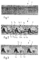
- FIG. 1 shows a ribbon-shaped warp knitted fabric 1, which serves as the basic knitted fabric 2, on which, according to FIG. 2, figure patterns 4 are knitted, which are formed from four figure pattern parts 4a, 4b, 4c, 4d with corresponding figure threads 6a, 6b, 6c, 6d.
- the figure threads lie floating on the base fabric 2 outside the figure patterns.
- FIG. 3 shows the base fabric 2 of FIG. 2 provided with figure patterns 4 after the floating figure thread sections 7a, 7b, 7c, 7d have been separated.
- FIGS. 4 and 5 show a first system for producing a warp knitted fabric according to FIGS. 1 to 3.
- the system contains a warp knitting machine 8, which in the present example is designed as a crochet galloon machine.
- a crochet gallon machine is described for example in WO 85/01527 and WO 85/04911.
- Forward and returning knitting needles 10 are attached to a reciprocating knitting needle bar 12.
- the knitting needles 10 designed as pusher needles contain pusher 14 which are moved back and forth by means of a pusher bar 16.
- the knitting needles 10 are guided over a tapping rail 18, which is preceded by a guide bar 20.
- the knock-off rail 18 and the guide bar 20 form a gap 22 for the removal of the warp knitted fabric.
- the knitting needles 10 are warp thread guides 24 upstream, which swing up and down on a warp thread guide 26 and are guided back and forth.
- a lever mechanism 28 is used for the drive.
- the warp thread guides 24 place the warp threads 30 in a circular motion in the knitting needles 10.
- a first laying bar 32 with thread guides 34 for introducing a basic thread 36 is arranged.
- a second laying bar 38 contains thread guides 40 for feeding a rubber thread 42.
- a pattern laying bar 44 with pattern thread guides 46 is shown, which is used for feeding a figure thread 6. Although only one pattern laying bar 44 with pattern thread guides 46 is shown, several of them can also be arranged for feeding several figure threads, such as figure threads 6a, 6b, 6c, 6d of FIG.
- the figure thread is fed in and integrated in the weft effect.
- the pattern laying bar 44 is actuated in a manner not shown with a laying bar drive which is electronically controlled. This makes it very easy to economically produce figure patterns with any repeats and in any layout.
- the knitting point 48 is followed by a take-off device 50 with rollers 52 arranged in pairs, via which the patterned warp knitted fabric 1 is drawn off, which consists of the basic knitted fabric 2 and the figure patterns 4 from the figure thread 6. Between the figure patterns 4, the figure thread 6 has floating figure thread sections 7 lying on the base fabric 2.
- the warp knitting machine 8 is followed by a separating device 54, to which the warp knitted fabric 1 is fed via a deflection roller 56.
- the separating device 54 has a guide 58, via which the warp knit 1 is guided to a further take-off device 60, which preferably runs more slowly than the take-off device 50 of the warp knitting machine, so that the warp knitted fabric 1 is longitudinally relaxed on the guide 58.
- the guide 58 is associated with a thread lifting device 62, which is designed as a suction device and serves to lift the floating figure thread sections 7 from the basic knitted fabric 2, so that they are separated from one another downstream thermal cutting device 66 can be separated.
- the separated figure thread sections 7 are sucked off through a nozzle 68 of the suction device 64 and can be collected in a collecting container, not shown here.
- FIG. 5 shows the separating device 54 in detail.
- the thermal cutting device 66 has an electrically heatable cutting wire 70 which is fastened in supports 72 arranged on both sides of the guide 58. On one side, a clamping screw 74 is used for fixation. On the other hand, a bolt 76 is clamped to the cutting wire 70 by means of a clamping screw 78, on which a spring 80 for prestressing the cutting wire 70 is supported.
- the cutting wire 70 has a current flowing through it in a manner not shown in detail and is thereby heated.
- the cutting wire 70 lies directly above the warp knitted fabric 1 guided over the guide 58 and separates the floating figure thread sections 7, which are lifted off the basic knitted fabric 2 by means of the nozzle 68.
- the ends of the floating figure threads which are preferably made of thermoplastic material, are melted and secured by the thermal cutting.
- FIG. 6 shows a further severing device 54a, which is designed analogously to the severing device of FIGS. 4 and 5, but the thread lifting device 62a is not designed as a suction device but as a rotting brush 82. This is associated with a suction device 84 for the removal of the cut figure thread sections 7.
- FIG. 7 shows a further separation device 54b, which is designed thermally and has a flame burner 86, which is preferably designed as a gas burner.
- the gas supplied via a line 88 is passed on to a nozzle 90, the gas flow being controllable by means of a regulator 92.
- the on the Flame 94 generated by nozzle 90 is used to burn or melt the floating figure thread sections 7 of the warp knitted fabric 1.
- a suction device 64 in turn serves as thread lifting device 62 and to suck off the separated figure thread sections.
Abstract
Description
Die Erfindung betrifft ein Verfahren zur Herstellung eines Kettengewirks, insbesondere eines Häkelgalongewirks gemäss Oberbegriff des Anspruches 1 sowie ein nach dem Verfahren hergestelltes Kettengewirk gemäss Anspruch 7 sowie eine Anlage zur Durchführung des Verfahrens gemäss Oberbegriff des Anspruches 8.The invention relates to a method for producing a warp knitted fabric, in particular a crocheted galgon knitted fabric according to the preamble of
Die US-A-5 007 253 beschreibt ein Verfahren, ein Kettengewirk sowie eine Anlage der eingangs genannten Art, dabei werden die flottierenden Figurfadenabschnitte zunächst von senkrecht zu Ebene des Kettengewirks angeordneten sichelartigen Messern erfasst und geschnitten. An einer weiteren Station werden die nun freiliegenden Abschnitte der flottierenden Figurfäden angehoben und von einer Schneidwalze mit schraubenlinienartig angeordneten Messern abgeschnitten. Das Verfahren und die Anlage sind relativ kompliziert, da für jede Bahn der flottierenden Figurfadenabschnitte ein gesondertes sichelartiges Messer erforderlich ist, das überdies beim Wechsel der Musterung jeweils neu eingestellt werden muss. Ausserdem können insbesondere flottierende Figurfadenabschnitte die in Laufrichtung des Kettengewirks liegen, nicht erfasst werden. Ferner besteht die Gefahr, dass sich die abgeschnittenen Figurfäden im Kettengewirk lösen, da die Enden nicht fixiert sind. Dieser Stand der Technik ist also relativ kompliziert und in der Handhabung umständlich und ermöglicht nur eine beschränkte Musterung.US-A-5 007 253 describes a method, a warp knitted fabric and a system of the type mentioned at the outset, in which case the floating figure thread sections are first gripped and cut by sickle-like knives arranged perpendicular to the warp knit plane. At a further station, the now exposed sections of the floating figure threads are lifted and cut off by a cutting roller with knives arranged in the manner of a helix. The method and the system are relatively complicated, since a separate sickle-like knife is required for each path of the floating figure thread sections, which knife must also be readjusted when the pattern changes. In addition, floating figure thread sections lying in the running direction of the warp knitted fabric, in particular, cannot be detected. There is also a risk that the cut figure threads loosen in the warp knit, since the ends are not fixed. This prior art is therefore relatively complicated and cumbersome to handle and only allows a limited pattern.
Aufgabe der Erfindung ist es, ein Verfahren zur Herstellung eines Kettengewirks, insbesondere eines Häkelgalongewirks mit Figurmustern, ferner das gemusterte Kettengewirk sowie eine Anlage zur Durchführung des Verfahrens der eingangs genannten Art weiter zu verbessern.The object of the invention is to further improve a process for the production of a warp knitted fabric, in particular a crocheted gauze knit with figure patterns, furthermore the patterned warp knitted fabric and an installation for carrying out the method of the type mentioned at the beginning.
Die Aufgabe wird erfindungsgemäss gelöst durch:
- a) das Verfahren gemäss
Anspruch 1; - b) das Kettengewirk gemäss
Anspruch 7 und - c) die Anlage gemäss
Anspruch 8.
- a) the method according to
claim 1; - b) the warp knitted fabric according to
claim 7 and - c) the system according to
claim 8.
Durch das Abtrennen der flottierenden Figurfadenabschnitte, z.B. gemäss Anspruch 3 oder 4, kann das Abtrennen nicht nur an einer einzigen Station durchgeführt werden, sondern es können auf einfachste Art und Weise sämtliche auch in Längsrichtung des bewegten Kettengewirks liegende flottierende Figurfadenabschnitte erfasst werden. Durch das thermische Schneiden erhalten die im Grundgewirk verbleibenden Figurfäden, sofern sie aus thermoplastischem Material bestehen, an den Enden einen Schmelzkopf, der den Figurfaden fixiert und somit ein Lösen aus dem Grundgewirk verhindert oder zumindest erschwert. Eine Neueinstellung der Abtrennvorrichtung ist bei einem Wechsel der Musterung in der Regel nicht erforderlich. Das Verfahren und die Anlage sind also äusserst einfach und benötigen nur geringsten Wartungs- und Einstellaufwand.By separating the floating figure thread sections, e.g. According to claim 3 or 4, the severing can not only be carried out at a single station, but all floating figurative thread sections lying in the longitudinal direction of the moving warp knitted fabric can also be detected in the simplest way. Through thermal cutting, the figure threads remaining in the basic knitting, if they are made of thermoplastic material, are provided with a melting head at the ends, which fixes the figure thread and thus prevents or at least makes it difficult to detach from the basic knitting. It is generally not necessary to readjust the separating device when changing the pattern. The process and the system are extremely simple and require very little maintenance and adjustment.
Dadurch, dass der Figurfaden figurseitig zwischen den Figurmustern flottierend auf dem Grundgewirk angeordnet wird, ergibt sich eine wesentliche Vereinfachung des Herstellungsverfahrens und eine grössere Variationsbreite der Musterung. Dennoch wirkt der flottierend auf dem Grundgewirk angeordnete Figurfaden nicht störend, da er nach der Herstellung des Kettengewirks abgetrennt wird, so dass nur noch das reine eingebundene Figurmuster sichtbar ist. Daraus resultieren weitere wesentliche Vorteile. So kann das Kettengewirk wesentlich dünner und mit einer Vielzahl von Figurmustern in verschiedenen sich überlappenden Farben ausgeführt sein. Der Materialverbrauch ist geringer, da Deckfäden und deren Einbindungen entfallen. Die Variationsbreite der Figurmusterung wird auch dadurch grösser, dass die bisher erforderlichen Legestangen für die Deckfäden wegfallen und zur Figurmusterung verwendet werden können. Das Kettengewirk ist auch wesentlich schöner und ansprechender, da es im Zwischenfigurbereich eine homogene Struktur des Grundgewirks, d.h. ohne Durchschimmern von abgedeckten Figurfäden aufweist. Auch die Rückseite des so gemusterten Kettengewirks weist in der Struktur des Grundgewirks eine grosse Homogenität auf, da hier ebenfalls ein Durchschimmern von abgedeckten Figurfäden im Zwischenfigurbereich entfällt. Besonders vorteilhaft sind Kettengewirke, die im Schusseffekt gemustert sind, da diese sehr fein strukturiert sein können. Die Feinheit der Bindungsstelle ist lediglich abhängig von der Anzahl Maschen pro Zentimeter, die eingebunden werden. Somit ist die Bindungsfeinheit nicht von der Maschenteilung abhängig wie beim bisherigen im Ketteneffekt gemusterten Kettengewirk. Die Vorteile der Schusseffektmusterung liegen also einerseits in einer feinen Bindungsstruktur und andererseits in einem Figurmuster, das reliefartig über dem Grundgewirk vorsteht. Nach dem neuen Verfahren können im Schusseffekt gemusterte Kettengewirke mit sich überlappenden Figuren und Figurteilen in beliebigen Farben hergestellt werden. Bei Verwendung von Kettenwirkmaschinen, insbesondere Häkelgalonmaschinen mit elektronisch gesteuertem Legestangenantrieb können auf einfachste Weise Figurmuster mit langen Rapporten in beliebiger Legung auf wirtschaftliche Weise erstellt werden.The fact that the figure thread is floating between the figure patterns on the basic knitted fabric results in a significant simplification of the manufacturing process and a greater variation in the pattern. Nevertheless, the figure thread floating on the basic knitted fabric does not have a disturbing effect, since it is cut off after the warp knit has been made, so that only the pure, integrated figure pattern is visible. This results in further significant advantages. The warp knit can be much thinner and with a variety of Figure patterns can be made in different overlapping colors. The material consumption is lower because there are no cover threads and their inclusions. The range of variation in figure patterning also increases because the laying bars previously required for the cover threads are eliminated and can be used for figure patterning. The warp knitted fabric is also much nicer and more appealing, since it has a homogeneous structure of the basic knitted fabric in the intermediate figure area, ie without covered figure threads showing through. The back of the warp knit patterned in this way also shows great homogeneity in the structure of the basic knitted fabric, since here too there is no shimmering through of covered figure threads in the intermediate figure area. Warp knits that are patterned in the weft effect are particularly advantageous since they can be very finely structured. The fineness of the binding site depends only on the number of stitches per centimeter that are integrated. This means that the fineness of the weave is not dependent on the stitch division, as in the previous warp knitted pattern. The advantages of weft effect patterning are, on the one hand, a fine weave structure and, on the other hand, a figure pattern that projects in relief above the basic knitted fabric. With the new process, warp-knitted warp knitted fabrics with overlapping figures and figure parts can be made in any color. When using warp knitting machines, in particular crochet gallon machines with electronically controlled laying bar drives, figure patterns with long repeats in any position can be created in an economical manner.
Durch das vorliegende Verfahren und die entsprechende Anlage werden die bis heute für gemusterte Artikel erforderlichen Farbdruckoperationen eliminiert. Dies bedeutet eine wesentliche Kosteneinsparung, wirtschaftlichere Fertigung von Kettengewirken, insbesondere Bändern wie Hosenträger, Gurtbänder, Unterwäschebänder, Spitzenbänder und dergleichen.The present method and the corresponding system eliminate the color printing operations that are still required for patterned articles. This means a substantial cost saving, more economical production of warp knitted fabrics, in particular straps such as braces, webbing straps, underwear straps, lace straps and the like.
Vorteilhafte Ausgestaltungen des Verfahren sind in den Ansprüchen 2 bis 6 und vorteilhafte Ausbildungen der Anlage in den Ansprüchen 9 bis 16 beschrieben.Advantageous embodiments of the method are described in
Grundsätzlich ist es möglich, das Abtrennen der flottierenden Figurfadenabschnitte räumlich und zeitlich unabhängig von dem Wirkvorgang durchzuführen. Vorteilhafter ist jedoch eine Ausbildung des Verfahrens nach Anspruch 2, wonach das Wirken und Abtrennen der flottierenden Figurfadenabschnitte in direkt aufeinanderfolgenden Arbeitsschritten erfolgen.In principle, it is possible to separate the floating figure thread sections spatially and temporally independently of the knitting process. However, it is more advantageous to design the method according to
Das Abtrennen der flottierenden Figurfadenabschnitte wird durch das Verfahren nach Anspruch 4 erleichtert. Vorteilhaft ist auch eine Weiterbildung des Verfahrens nach Anspruch 6, wodurch die Qualität der Figurmuster verbessert wird.The separation of the floating figure thread sections is facilitated by the method according to
Die Abtrennvorrichtung kann unabhängig von der Kettenwirkmaschine angeordnet sein. Vorteilhafter ist jedoch eine Ausbildung nach Anspruch 9.The separation device can be arranged independently of the warp knitting machine. However, an embodiment according to claim 9 is more advantageous.
Besonders vorteilhaft ist eine Ausbildung der Abtrennvorrichtung nach Anspruch 10. Gegebenenfalls kann es zweckmässig sein, gemäss Anspruch 11 einen Flammenbrenner zum Abtrennen oder Abschmelzen der flottierenden Figurfadenabschnitte zu verwenden.A design of the severing device according to claim 10 is particularly advantageous. If appropriate, it can be expedient to use a flame burner for severing or melting the floating figure thread sections.
In jedem Falle ist es zweckmässig, die Anlage gemäss Anspruch 12 mit einer Transportvorrichtung zum längsentspannten Transportieren des Kettengewirks an der Abtrennvorrichtung zu versehen.In any case, it is expedient to provide the system according to
Das Abtrennen der flottierenden Figurfadenabschnitte wird durch eine Ausgestaltung der Anlage nach Anspruch 13 erleichtert. Besonders vorteilhaft ist eine Ausgestaltung der Fadenabhebvorrichtung nach Anspruch 14, wobei die Saugvorrichtung gleichzeitig auch zum Abführen der abgetrennten Figurfadenabschnitte dienen kann. Auch eine Ausgestaltung nach Anspruch 15 ist zum Abheben der flottierenden Figurfadenabschnitte möglich.The separation of the floating figure thread sections is facilitated by an embodiment of the system according to claim 13. An embodiment of the thread lifting device according to claim 14 is particularly advantageous, wherein the suction device can also serve at the same time for removing the separated fig thread sections. An embodiment according to claim 15 is also for lifting of floating figure thread sections possible.
In jedem Falle ist es zweckmässig, wenn die Anlage gemäss Anspruch 16 mit einer Absaugvorrichtung für die abgetrennten Figurfadenabschnitte versehen ist.In any case, it is expedient if the system is provided with a suction device for the separated fig thread sections.
Nach der Erfindung lassen sich die verschiedensten Kettengewirke, insbesondere Häkelgalongewirke mit den verschiedensten Figurmustern herstellen. Besonders vorteilhaft ist die Erfindung zur Herstellung von Bändern der verschiedensten Art, insbesondere von Hosenträgern, Gurtbändern, Unterwäschebändern, Spitzenbändern und dergleichen.According to the invention, a wide variety of warp knitted fabrics, in particular crocheted gallon knitted fabrics with a wide variety of figure patterns, can be produced. The invention is particularly advantageous for producing ribbons of all kinds, in particular braces, belt straps, underwear straps, lace straps and the like.
Ausführungsbeispiele des Gegenstandes der Erfindung werden nachfolgend anhand schematischer Zeichnungen näher beschrieben, dabei zeigen:
Figur 1- ein ungemustertes Kettengewirk in Draufsicht auf die Gutseite;
Figur 2- das Kettengewirk der
Figur 1 mit Figurmuster und flottierenden Figurfadenabschnitten; - Figur 3
- das Kettengewirk der
Figur 2 nach dem Abtrennen der flottierenden Figurfadenabschnitte; Figur 4- eine erste Anlage zur Herstellung bandförmiger Kettengewirke mit einer thermischen Schneidvorrichtung, im Vertikalschnitt;
- Figur 5
- die thermische Schneidvorrichtung in Ansicht V der
Figur 4 und in grösserem Massstab sowie teilweise geschnitten; - Figur 6
- die Abtrennvorrichtung der Anlage nach
Figur 4 mit abgewandelter Fadenanhebvorrichtung; und Figur 7- eine weitere Abtrennvorrichtung mit einem Flammenbrenner, im Vertikalschnitt.
- Figure 1
- an unpatterned warp knitted fabric in top view of the good side;
- Figure 2
- the warp knitted fabric of FIG. 1 with figure pattern and floating figure thread sections;
- Figure 3
- the warp knitted fabric of FIG. 2 after severing the floating figure thread sections;
- Figure 4
- a first plant for the production of ribbon-shaped warp knitted fabrics with a thermal cutting device, in vertical section;
- Figure 5
- the thermal cutting device in view V of Figure 4 and on a larger scale and partially cut;
- Figure 6
- the separating device of the system according to Figure 4 with a modified thread lifting device; and
- Figure 7
- another separation device with a flame burner, in vertical section.
Die Figur 1 zeigt ein bandförmiges Kettengewirk 1, welches als Grundgewirk 2 dient, auf dem gemäss Figur 2 Figurmuster 4 eingewirkt sind, die aus vier Figurmusterteilen 4a,4b,4c,4d mit entsprechenden Figurfäden 6a,6b,6c,6d gebildet sind. Die Figurfäden liegen ausserhalb der Figurenmuster flottierend auf dem Grundgewirk 2. Die Figur 3 zeigt das mit Figurmustern 4 versehene Grundgewirk 2 der Figur 2 nach dem Abtrennen der flottierenden Figurfadenabschnitte 7a,7b,7c,7d.FIG. 1 shows a ribbon-shaped warp knitted
Die Figuren 4 und 5 zeigen eine erste Anlage zur Herstellung eines Kettengewirks gemäss den Figuren 1 bis 3. Die Anlage enthält eine Kettenwirkmaschine 8, die im vorliegenden Beispiel als Häkelgalonmaschine ausgestaltet ist. Eine solche Häkelgalonmaschine ist beispielsweise in der WO 85/01527 und der WO 85/04911 beschrieben. Vor- und zurückgehende Wirknadeln 10 sind an einer hin- und hergehenden Wirknadelbarre 12 befestigt. Die als Schiebernadeln ausgestalteten Wirknadeln 10 enthalten Schieber 14, die mittels einer Schieberbarre 16 hin- und herbewegt werden. Die Wirknadeln 10 sind über eine Abschlagschiene 18 geführt, der eine Führungsleiste 20 vorgelagert ist. Die Abschlagschiene 18 und die Führungsleiste 20 bilden einen Spalt 22 zur Abführung des hergestellten Kettengewirks. Den Wirknadeln 10 sind Kettfadenführer 24 vorgelagert, die an einer Kettfadenlegeschiene 26 auf- und abschwingend sowie hin- und hergehend geführt sind. Zum Antrieb dient ein Hebelgetriebe 28. Die Kettfadenführer 24 legen die Kettfäden 30 in einer kreisenden Bewegung in die Wirknadeln 10. Oberhalb der Wirknadelebene ist eine erste Legestange 32 mit Fadenführern 34 zur Einbringung eines Grundfadens 36 angeordnet. Eine zweite Legestange 38 enthält Fadenführer 40 zur Zuführung eines Gummifadens 42. Weiter ist eine Musterlegestange 44 mit Musterfadenführern 46 dargestellt, die zur Zuführung eines Figurfadens 6 dient. Obwohl nur eine Musterlegestange 44 mit Musterfadenführern 46 gezeigt ist, können deren auch mehrere angeordnet sein zur Zuführung mehrerer Figurfäden, wie beispielsweise der Figurfäden 6a,6b,6c,6d der Figur 2. Der Figurfaden wird im Schusseffekt zugeführt und eingebunden. Hierzu wird die Musterlegestange 44 in nicht näher dargestellter Weise mit einem Legestangenantrieb betätigt, der elektronisch gesteuert ist. Damit können auf einfachste Weise Figurmuster mit beliebigen Rapporten und in beliebiger Legung wirtschaftlich hergestellt werden. Der Wirkstelle 48 ist eine Abzugsvorrichtung 50 mit paarweise angeordneten Walzen 52 nachgeordnet, über die das gemusterte Kettengewirk 1 abgezogen wird, welches aus dem Grundgewirk 2 und den Figurmustern 4 aus dem Figurfaden 6 besteht. Zwischen den Figurmustern 4 weist der Figurfaden 6 auf dem Grundgewebe 2 flottierend liegende Figurfadenabschnitte 7 auf.FIGS. 4 and 5 show a first system for producing a warp knitted fabric according to FIGS. 1 to 3. The system contains a
Der Kettenwirkmaschine 8 ist eine Abtrennvorrichtung 54 nachgeschaltet, der das Kettengewirk 1 über eine Umlenkrolle 56 zugeführt wird. Die Abtrennvorrichtung 54 weist eine Führung 58 auf, über die das Kettengewirk 1 zu einer weiteren Abzugsvorrichtung 60 geführt ist, die vorzugsweise langsamer läuft als die Abzugsvorrichtung 50 der Kettenwirkmaschine, so dass das Kettengewirk 1 an der Führung 58 längsentspannt ist. Der Führung 58 ist eine Fadenanhebvorrichtung 62 zugeordnet, die als Saugvorrichtung ausgestaltet ist und dazu dient, die flottierenden Figurfadenabschnitte 7 vom Grundgewirk 2 abzuheben, so dass sie von einer nachgeordneten thermischen Schneidvorrichtung 66 abgetrennt werden können. Die abgetrennten Figurfadenabschnitte 7 werden durch eine Düse 68 der Saugvorrichtung 64 abgesaugt und können in einem hier nicht näher dargestellten Auffangbehälter aufgefangen werden.The
Die Figur 5 zeigt die Abtrennvorrichtung 54 im Detail. Die thermische Schneidvorrichtung 66 weist einen elektrisch heizbaren Schneiddraht 70 auf, der in beidseits der Führung 58 angeordneten Trägern 72 befestigt ist. Auf der einen Seite dient eine Klemmschraube 74 zur Fixierung. Auf der anderen Seite ist am Schneiddraht 70 ein Bolzen 76 mittels einer Klemmschraube 78 festgeklemmt, an den sich eine Feder 80 zur Vorspannung des Schneiddrahtes 70 abstützt. Der Schneiddraht 70 ist in nicht näher dargestellter Weise von einem Strom durchflossen und wird dadurch aufgeheizt. Der Schneiddraht 70 liegt unmittelbar über dem über die Führung 58 geführten Kettengewirk 1 und trennt die flottierenden Figurfadenabschnitte 7 ab, die mittels der Düse 68 vom Grundgewirk 2 abgehoben sind. Durch das thermische Schneiden werden die Enden der flottierenden Figurfäden, die vorzugsweise aus thermoplastischem Material bestehen, angeschmolzen und gesichert.FIG. 5 shows the separating
Die Figur 6 zeigt eine weitere Abtrennvorrichtung 54a, die analog der Abtrennvorrichtung der Figuren 4 und 5 ausgebildet ist, wobei jedoch die Fadenabhebvorrichtung 62a nicht als Saugvorrichtung sondern als rottierende Bürste 82 ausgestaltet ist. Dieser ist eine Absaugvorrichtung 84 zum Abtransport der abgeschnittenen Figurfadenabschnitte 7 zugeordnet.FIG. 6 shows a
Die Figur 7 zeigt eine weitere Abtrennvorrichtung 54b, die thermisch ausgestaltet ist und einen Flammenbrenner 86 aufweist, der vorzugsweise als Gasbrenner ausgebildet ist. Das über eine Leitung 88 zugeführte Gas wird an eine Düse 90 weitergeleitet, wobei der Gasstrom mittels eines Reglers 92 regelbar ist. Die an der Düse 90 erzeugte Flamme 94 dient zum Abbrennen oder Abschmelzen der flottierenden Figurfadenabschnitte 7 des Kettengewirks 1. Eine Saugvorrichtung 64 dient wiederum als Fadenanhebvorrichtung 62 und zum Absaugen der abgetrennten Figurfadenabschnitte.FIG. 7 shows a
- 11
- KettengewirkWarp knit
- 22nd
- GrundgewirkBasic fabric
- 44th
- FigurmusterFigure pattern
- 4a4a
- FigurteilFigure part
- 4b4b
- FigurteilFigure part
- 4c4c
- FigurteilFigure part
- 4d4d
- FigurteilFigure part
- 66
- FigurfadenFigure thread
- 6a6a
- FigurfadenFigure thread
- 6b6b
- FigurfadenFigure thread
- 6c6c
- FigurfadenFigure thread
- 6d6d
- FigurfadenFigure thread
- 77
- FigurfadenabschnittFigure thread section
- 7a7a
- FigurfadenabschnittFigure thread section
- 7b7b
- FigurfadenabschnittFigure thread section
- 7c7c
- FigurfadenabschnittFigure thread section
- 7d7d
- FigurfadenabschnittFigure thread section
- 88th
- KettenwirkmaschineWarp knitting machine
- 1010th
- WirknadelKnitting needle
- 1212
- WirknadelbarreNeedle bar
- 1414
- SchieberSlider
- 1616
- SchieberbarreSlide bar
- 1818th
- AbschlagschieneTee rail
- 2020th
- FührungsleisteGuide bar
- 2222
- Spaltgap
- 2424th
- KettfadenführerWarp thread guide
- 2626
- KettfadenlegeschieneWarp thread guide
- 2828
- HebelgetriebeLever gear
- 3030th
- KettfadenWarp thread
- 3232
- LegestangeLaying bar
- 3434
- FadenführerThread guide
- 3636
- GrundfadenBasic thread
- 3838
- LegestangeLaying bar
- 4040
- FadenführerThread guide
- 4242
- GummifadenRubber thread
- 4444
- MusterlegestangePattern laying bar
- 4646
- MusterfadenführerSample thread guide
- 4848
- WirkstelleActive site
- 5050
- AbzugsvorrichtungTrigger device
- 5252
- Walzeroller
- 5454
- AbtrennvorrichtungDisconnecting device
- 54a54a
- AbtrennvorrichtungDisconnecting device
- 54b54b
- AbtrennvorrichtungDisconnecting device
- 5656
- UmlenkrollePulley
- 5858
- Führungguide
- 6060
- AbzugsvorrichtungTrigger device
- 6262
- FadenanhebvorrichtungThread lifting device
- 62a62a
- FadenanhebvorrichtungThread lifting device
- 62b62b
- FadenanhebvorrichtungThread lifting device
- 6464
- SaugvorrichtungSuction device
- 6666
- thermische Schneidvorrichtungthermal cutting device
- 6868
- Düsejet
- 7070
- SchneiddrahtCutting wire
- 7272
- Trägercarrier
- 7474
- KlemmschraubeClamping screw
- 7676
- Bolzenbolt
- 7878
- KlemmschraubeClamping screw
- 8080
- Federfeather
- 8282
- rotierende Bürsterotating brush
- 8484
- AbsaugvorrichtungSuction device
- 8686
- FlammenbrennerFlame burner
- 8888
- Leitungmanagement
- 9090
- Düsejet
- 9292
- ReglerRegulator
- 9494
- Flammeflame
Claims (16)
Applications Claiming Priority (2)
| Application Number | Priority Date | Filing Date | Title |
|---|---|---|---|
| CH2571/91 | 1991-09-02 | ||
| CH257191 | 1991-09-02 |
Publications (2)
| Publication Number | Publication Date |
|---|---|
| EP0530632A1 true EP0530632A1 (en) | 1993-03-10 |
| EP0530632B1 EP0530632B1 (en) | 1996-02-14 |
Family
ID=4236794
Family Applications (1)
| Application Number | Title | Priority Date | Filing Date |
|---|---|---|---|
| EP19920114383 Expired - Lifetime EP0530632B1 (en) | 1991-09-02 | 1992-08-24 | Method and device for making warp knit wear, especially galloon crochet wear and warp knit wear obtained by this method |
Country Status (4)
| Country | Link |
|---|---|
| EP (1) | EP0530632B1 (en) |
| DE (1) | DE59205338D1 (en) |
| ES (1) | ES2084226T3 (en) |
| TW (1) | TW203638B (en) |
Cited By (3)
| Publication number | Priority date | Publication date | Assignee | Title |
|---|---|---|---|---|
| CN1049028C (en) * | 1994-09-10 | 2000-02-02 | 卡尔迈尔纺织机械制造有限公司 | Method for production of pattern braided article and warp-knitting machine thereof |
| DE102006055498A1 (en) * | 2006-11-24 | 2008-06-12 | Karl Mayer Textilmaschinenfabrik Gmbh | Method for producing a knitted fabric |
| CN113388957A (en) * | 2021-06-18 | 2021-09-14 | 台州铭龙塑业科技股份有限公司 | Production method of three-dimensional crocheted fabric and foot pad with three-dimensional crocheted surface layer |
Families Citing this family (1)
| Publication number | Priority date | Publication date | Assignee | Title |
|---|---|---|---|---|
| CN104975427B (en) * | 2014-04-04 | 2018-05-25 | 卡尔迈尔纺织机械制造有限公司 | The method for producing woven product |
Citations (7)
| Publication number | Priority date | Publication date | Assignee | Title |
|---|---|---|---|---|
| US3119167A (en) * | 1962-10-17 | 1964-01-28 | Curtis Marble Machine Co | Shearing apparatus for textile fabrics |
| US3217680A (en) * | 1964-04-01 | 1965-11-16 | Harris Marshall Hosiery Mills | Cutting device |
| DE1635270A1 (en) * | 1967-06-23 | 1972-04-06 | Mueller Franz | Method and device for treating textile webs |
| DE2244114A1 (en) * | 1972-09-08 | 1974-03-14 | Wtz Textile | Raschel weft patterning - with long throw patterns having long repeats applied onto fabrics |
| WO1985001527A1 (en) * | 1983-10-05 | 1985-04-11 | Textilma Ag | Installation for the drive and control of the feed and elevation of pirn supports along the needle board for knitting machines, galloon and crochet machines and the like |
| WO1985004911A1 (en) * | 1984-04-26 | 1985-11-07 | Textilma Ag | Process for manufacturing a patterned warp-knitted material and a warp knitting machine for its use |
| US5007253A (en) * | 1988-03-25 | 1991-04-16 | Thomas Rahner | Portable lace clipping and shearing apparatus for synchronous operation with a lace-knitting machine |
-
1991
- 1991-09-13 TW TW80107263A patent/TW203638B/zh active
-
1992
- 1992-08-24 DE DE59205338T patent/DE59205338D1/en not_active Expired - Fee Related
- 1992-08-24 EP EP19920114383 patent/EP0530632B1/en not_active Expired - Lifetime
- 1992-08-24 ES ES92114383T patent/ES2084226T3/en not_active Expired - Lifetime
Patent Citations (7)
| Publication number | Priority date | Publication date | Assignee | Title |
|---|---|---|---|---|
| US3119167A (en) * | 1962-10-17 | 1964-01-28 | Curtis Marble Machine Co | Shearing apparatus for textile fabrics |
| US3217680A (en) * | 1964-04-01 | 1965-11-16 | Harris Marshall Hosiery Mills | Cutting device |
| DE1635270A1 (en) * | 1967-06-23 | 1972-04-06 | Mueller Franz | Method and device for treating textile webs |
| DE2244114A1 (en) * | 1972-09-08 | 1974-03-14 | Wtz Textile | Raschel weft patterning - with long throw patterns having long repeats applied onto fabrics |
| WO1985001527A1 (en) * | 1983-10-05 | 1985-04-11 | Textilma Ag | Installation for the drive and control of the feed and elevation of pirn supports along the needle board for knitting machines, galloon and crochet machines and the like |
| WO1985004911A1 (en) * | 1984-04-26 | 1985-11-07 | Textilma Ag | Process for manufacturing a patterned warp-knitted material and a warp knitting machine for its use |
| US5007253A (en) * | 1988-03-25 | 1991-04-16 | Thomas Rahner | Portable lace clipping and shearing apparatus for synchronous operation with a lace-knitting machine |
Cited By (4)
| Publication number | Priority date | Publication date | Assignee | Title |
|---|---|---|---|---|
| CN1049028C (en) * | 1994-09-10 | 2000-02-02 | 卡尔迈尔纺织机械制造有限公司 | Method for production of pattern braided article and warp-knitting machine thereof |
| DE102006055498A1 (en) * | 2006-11-24 | 2008-06-12 | Karl Mayer Textilmaschinenfabrik Gmbh | Method for producing a knitted fabric |
| DE102006055498B4 (en) * | 2006-11-24 | 2008-08-07 | Karl Mayer Textilmaschinenfabrik Gmbh | Method for producing a knitted fabric |
| CN113388957A (en) * | 2021-06-18 | 2021-09-14 | 台州铭龙塑业科技股份有限公司 | Production method of three-dimensional crocheted fabric and foot pad with three-dimensional crocheted surface layer |
Also Published As
| Publication number | Publication date |
|---|---|
| ES2084226T3 (en) | 1996-05-01 |
| TW203638B (en) | 1993-04-11 |
| EP0530632B1 (en) | 1996-02-14 |
| DE59205338D1 (en) | 1996-03-28 |
Similar Documents
| Publication | Publication Date | Title |
|---|---|---|
| EP0082538B1 (en) | Circular knitting machine for manufacturing cut pile plush fabric | |
| DE1485502B2 (en) | TUFTING MACHINE FOR THE PRODUCTION OF TUFTING PRODUCTS WITH CLOSED AND CUT LOOPS | |
| EP0295703B1 (en) | Method for manufacturing a patterned plush article and a multi-system circular knitting machine for carrying out this method | |
| CH690182A5 (en) | Process and warp knitting machine for producing a patterned knitwear. | |
| EP0043135B1 (en) | Method of producing patterned plush articles and circular knitting machine for this method | |
| DE2400722A1 (en) | METHOD AND DEVICE FOR MANUFACTURING SOFT CLOTHS | |
| EP0110271A2 (en) | Crocheting tool for manufacturing ribbons on a galloon crocheting machine | |
| DE4238250A1 (en) | Device on a warp knitting machine for crocheting an elastic band with fleece and possibly for crocheting picos, and elastic band produced with this device | |
| EP0530632B1 (en) | Method and device for making warp knit wear, especially galloon crochet wear and warp knit wear obtained by this method | |
| EP0293956B1 (en) | Method and device for treating knitting yarns along the knitwear edge | |
| DE19740200C1 (en) | Warp knitter guide bar with guide needles for the pattern and bonding yarns | |
| DE19802994C1 (en) | Laying system for yarn bands, used in knitter | |
| DE4228048C2 (en) | Warp knitting machine with inclusion knock-off boards that can be moved back and forth in the needle streets | |
| DE2601899C3 (en) | Method and device for manufacturing sacks | |
| DE2507815A1 (en) | DEVICE FOR FEEDING THE THREAD IN CIRCULAR KNITTING MACHINES WITH A FIXED NEEDLE CYLINDER AND ROTATING LOCKING SHEETS FOR THE MANUFACTURE OF OPEN KNITWEAR | |
| DE2847838A1 (en) | NEEDLE TONGUE GUIDE AND HIGH PILE CIRCULAR KNITTING MACHINE EQUIPPED WITH SUCH GUIDES | |
| EP0051059B1 (en) | Method of manufacturing an optionally patterned pile fabric, and circular knitting machine therefor | |
| EP0179072B1 (en) | Process for manufacturing a patterned warp-knitted material and a warp knitting machine for its use | |
| DE642696C (en) | Circular knitting machine | |
| DE3022086A1 (en) | Knitting mechanism for Raschel loom - has pattern guide strips moving only laterally and threads moved by selector | |
| DE606390C (en) | Fixed knitted goods and process for their manufacture | |
| EP0606585A2 (en) | Severing- and clamping device for front yarn, for embroidering machines | |
| DE1685144C3 (en) | Shuttle embroidery machine with a device for changing threads or colors or changing repeats | |
| DD201326B1 (en) | METHOD AND DEVICE FOR PREPARING CHENILLE ON CHAIN METAL MACHINES | |
| DE19604410C2 (en) | Method and device for separating textile threads from glass fibers |
Legal Events
| Date | Code | Title | Description |
|---|---|---|---|
| PUAI | Public reference made under article 153(3) epc to a published international application that has entered the european phase |
Free format text: ORIGINAL CODE: 0009012 |
|
| AK | Designated contracting states |
Kind code of ref document: A1 Designated state(s): CH DE ES GB IT LI |
|
| 17P | Request for examination filed |
Effective date: 19930206 |
|
| 17Q | First examination report despatched |
Effective date: 19941108 |
|
| GRAA | (expected) grant |
Free format text: ORIGINAL CODE: 0009210 |
|
| AK | Designated contracting states |
Kind code of ref document: B1 Designated state(s): CH DE ES GB IT LI |
|
| ITF | It: translation for a ep patent filed |
Owner name: ING. A. GIAMBROCONO & C. S.R.L. |
|
| REF | Corresponds to: |
Ref document number: 59205338 Country of ref document: DE Date of ref document: 19960328 |
|
| REG | Reference to a national code |
Ref country code: CH Ref legal event code: NV |
|
| REG | Reference to a national code |
Ref country code: ES Ref legal event code: FG2A Ref document number: 2084226 Country of ref document: ES Kind code of ref document: T3 |
|
| GBT | Gb: translation of ep patent filed (gb section 77(6)(a)/1977) |
Effective date: 19960502 |
|
| PLBE | No opposition filed within time limit |
Free format text: ORIGINAL CODE: 0009261 |
|
| STAA | Information on the status of an ep patent application or granted ep patent |
Free format text: STATUS: NO OPPOSITION FILED WITHIN TIME LIMIT |
|
| 26N | No opposition filed | ||
| REG | Reference to a national code |
Ref country code: GB Ref legal event code: IF02 |
|
| PGFP | Annual fee paid to national office [announced via postgrant information from national office to epo] |
Ref country code: DE Payment date: 20070822 Year of fee payment: 16 |
|
| PGFP | Annual fee paid to national office [announced via postgrant information from national office to epo] |
Ref country code: ES Payment date: 20070830 Year of fee payment: 16 |
|
| PGFP | Annual fee paid to national office [announced via postgrant information from national office to epo] |
Ref country code: CH Payment date: 20070815 Year of fee payment: 16 |
|
| PGFP | Annual fee paid to national office [announced via postgrant information from national office to epo] |
Ref country code: GB Payment date: 20070823 Year of fee payment: 16 |
|
| PGFP | Annual fee paid to national office [announced via postgrant information from national office to epo] |
Ref country code: IT Payment date: 20080826 Year of fee payment: 17 |
|
| REG | Reference to a national code |
Ref country code: CH Ref legal event code: PL |
|
| GBPC | Gb: european patent ceased through non-payment of renewal fee |
Effective date: 20080824 |
|
| PG25 | Lapsed in a contracting state [announced via postgrant information from national office to epo] |
Ref country code: LI Free format text: LAPSE BECAUSE OF NON-PAYMENT OF DUE FEES Effective date: 20080831 Ref country code: CH Free format text: LAPSE BECAUSE OF NON-PAYMENT OF DUE FEES Effective date: 20080831 |
|
| PG25 | Lapsed in a contracting state [announced via postgrant information from national office to epo] |
Ref country code: DE Free format text: LAPSE BECAUSE OF NON-PAYMENT OF DUE FEES Effective date: 20090303 |
|
| REG | Reference to a national code |
Ref country code: ES Ref legal event code: FD2A Effective date: 20080825 |
|
| PG25 | Lapsed in a contracting state [announced via postgrant information from national office to epo] |
Ref country code: GB Free format text: LAPSE BECAUSE OF NON-PAYMENT OF DUE FEES Effective date: 20080824 |
|
| PG25 | Lapsed in a contracting state [announced via postgrant information from national office to epo] |
Ref country code: ES Free format text: LAPSE BECAUSE OF NON-PAYMENT OF DUE FEES Effective date: 20080825 |
|
| PG25 | Lapsed in a contracting state [announced via postgrant information from national office to epo] |
Ref country code: IT Free format text: LAPSE BECAUSE OF NON-PAYMENT OF DUE FEES Effective date: 20090824 |