EP0532194A1 - Thermally-regulated flavor generator - Google Patents
Thermally-regulated flavor generator Download PDFInfo
- Publication number
- EP0532194A1 EP0532194A1 EP92307710A EP92307710A EP0532194A1 EP 0532194 A1 EP0532194 A1 EP 0532194A1 EP 92307710 A EP92307710 A EP 92307710A EP 92307710 A EP92307710 A EP 92307710A EP 0532194 A1 EP0532194 A1 EP 0532194A1
- Authority
- EP
- European Patent Office
- Prior art keywords
- flavor
- source
- distributed
- heat source
- heat
- Prior art date
- Legal status (The legal status is an assumption and is not a legal conclusion. Google has not performed a legal analysis and makes no representation as to the accuracy of the status listed.)
- Withdrawn
Links
Images


Classifications
-
- A—HUMAN NECESSITIES
- A24—TOBACCO; CIGARS; CIGARETTES; SIMULATED SMOKING DEVICES; SMOKERS' REQUISITES
- A24B—MANUFACTURE OR PREPARATION OF TOBACCO FOR SMOKING OR CHEWING; TOBACCO; SNUFF
- A24B15/00—Chemical features or treatment of tobacco; Tobacco substitutes, e.g. in liquid form
- A24B15/10—Chemical features of tobacco products or tobacco substitutes
- A24B15/16—Chemical features of tobacco products or tobacco substitutes of tobacco substitutes
- A24B15/165—Chemical features of tobacco products or tobacco substitutes of tobacco substitutes comprising as heat source a carbon fuel or an oxidized or thermally degraded carbonaceous fuel, e.g. carbohydrates, cellulosic material
-
- A—HUMAN NECESSITIES
- A24—TOBACCO; CIGARS; CIGARETTES; SIMULATED SMOKING DEVICES; SMOKERS' REQUISITES
- A24D—CIGARS; CIGARETTES; TOBACCO SMOKE FILTERS; MOUTHPIECES FOR CIGARS OR CIGARETTES; MANUFACTURE OF TOBACCO SMOKE FILTERS OR MOUTHPIECES
- A24D1/00—Cigars; Cigarettes
- A24D1/22—Cigarettes with integrated combustible heat sources, e.g. with carbonaceous heat sources
Definitions
- This invention relates to flavor generating articles which deliver flavor to the consumer during each individual puff of the article.
- Siegel U.S. Patent No. 2,907,686 describes a smoking article consisting of a charcoal rod and a separate carrier impregnated with flavorants and a synthetic "smoke" forming agent which is heated by the burning charcoal rod.
- the charcoal rod is coated with a concentrated sugar solution so as to form an impervious layer during burning. It was thought that this layer would contain the gases formed during flavor generating and concentrate the heat thus formed.
- Another smoking article described in US - A - 3,258,015, employs burning tobacco in the form of a conventional cigarette to heat a metallic cylinder containing a source of nicotine, such as reconstituted tobacco or tobacco extract.
- a source of nicotine such as reconstituted tobacco or tobacco extract.
- the vapors released from the material inside the metal tube mix with air inhaled through an open end of the tube which runs to the burning end of the flavor generating article.
- US - A - 3,356,094 describes a similar flavor generating article in which the tube becomes frangible upon heating, so that it would break off and not protrude when the surrounding tobacco had burned away.
- Our EP - A - 0 177 355 describes a smoking article which produces a nicotine-containing aerosol by heating, but not burning, a flavor generator.
- the flavor generator could be fabricated from a substrate material such as alumina, natural clays and the like, or tobacco filler.
- the flavor generator is impregnated with thermally releasable flavorants, including nicotine, glycerol, menthol and the like. Heating of the flavor generator is provided by hot gases formed as a result of the combustion of a fuel rod of pyrolized tobacco or other carbonaceous material.
- US - A - 4,714,082 shows a variation of the Hearn et al. article which employs a fuel element.
- the performance of the article is said to be improved by maximizing heat transfer between the fuel element and the aerosol generator. This is effected by preventing heat loss by insulation, and by enhancing heat transfer between the burning fuel and the flavor generator by a metallic conductor.
- a spun glass fiber insulator surrounds the fuel element and aerosol generator assembly.
- Our US - A - No. 4,991,606 describes a flavor generating article wherein the flavor bed is positioned relative to the heat source so that heat transfers from the heat source to the flavor bed by radiation and convection. Such a design produces substantially no visible sidestream smoke. Further improvements on such a design can be achieved with the incorporation of improved heat sources.
- Our EP - A - 0 372 985 describes a heat source made of iron carbide. Such a heat source produces virtually no carbon monoxide upon combustion.
- our EP - A - 0 430 658 describes a heat source made of metal nitride that produces virtually no carbon monoxide or nitrogen oxide.
- the flavor generating articles described above suffer from a number of design-related drawbacks which have prohibited the flavor generating articles from producing a constant quality of flavor delivery.
- the flavor source is arranged in a geometry where it is concentrated into a single three-dimensional "chamber" with the diameter and length of the chamber approximately the same as the diameter of the flavor generating article.
- the heat source which is also concentrated into its own individual "chamber,” is also arranged with a geometry similar to the flavor source.
- the "chambers" necessarily have dimensions on the order of the diameter of the flavor generating article, heat that is generated in the heat source must at times be transferred up to distances on the order of twice the diameter of the flavor generating article in order to heat the flavor source material that is most remote from the heat source. Because this distance can be large, the heat transfer properties of the article are inefficient. The large mass of material over which the heat must transfer serves as an unnecessary heat sink. As a result, the heat source of these devices is inefficient since it must generate more heat than a heat source in a structure where heat would not have to be transferred over large distances.
- a flavor generating article capable of producing a substantially constant quality of flavor delivery from the first to last puff of the article, as is obtained in conventional cigarettes.
- This ability of the present invention is achieved for the first time because a distributed flavor source is placed in thermal contact with a distributed heat source.
- Such a design allows for the heat to be directly transferred by conduction and convection from the heat source to the flavor source.
- Preferred embodiments have a flavor generating unit which is comprised of a distributed heat source, a distributed flavor source and an optional insulating material.
- the distributed flavor source is in thermal contact with the distributed heat source. Because of the distributed nature of the heat and flavor sources and because they are in thermal contact with each other, the present invention allows the quality of the individual puff to be precisely controlled and regulated. Accordingly, the present invention can produce the same flavor delivery, which is constant from puff to puff, as is obtained in conventional cigarettes.
- the basic flavor generating article of the present invention includes a distributed flavor source in thermal contact with a distributed heat source.
- flavor-containing substance i.e., a vapor or aerosol, or mixture thereof, containing flavored vapors or aerosols or other vapors or aerosol components
- thermal contact means that the distributed boundaries of the flavor source and heat source are adjacent each other and not necessarily in direct physical contact.
- the flavor source can be any material that can be distributed and placed in thermal contact with the distributed heat source of the present invention and which, when heated, releases a flavor-containing substance.
- Such materials can include as a component tobacco, reconstituted tobacco, tobacco condensates (condensed components of the smoke produced by the combustion of tobacco, leaving flavors and, possibly, nicotine), or tobacco extracts. These materials when heated generate or release a flavor-containing substance (which may include nicotine) which can be drawn in by the consumer.
- Any of these flavor generating materials can also include an aerosol-forming substance (i.e., aerosol precursor), such as glycerin, propylene glycol, 1,3-butanediol, water or the like. These materials give the "smoker” the perception of inhaling and exhaling "smoke” as in a conventional cigarette where tobacco is burned.
- a particularly preferred flavor source material is a composition such as that described in our EP - A - 0 352 107 which describes pelletized tobacco containing an aerosol-forming ingredient and a filler.
- This composition can be used in the pellet form or, instead of being formed into pellets, could be deposited as a sheet or coating, in conjunction with adhesion agents such as pectins, gums, or cellulose derivatives, such as carboxymethyl cellulose (CMC), or the like.
- adhesion agents such as pectins, gums, or cellulose derivatives, such as carboxymethyl cellulose (CMC), or the like.
- this sheet or coating-type of flavor source material is used, then the material is applied as a sheet or coating to the heat source.
- the pellets should have a size in the range of approximately 0.1 mm to approximately 0.5 mm.
- the flavor source material may also be applied to an inert insulating substrate in contact with the heat source, if such an insulating material is used in the flavor generating
- the tobacco pellets described above are preferably formed by combining in an extruder: particularized tobacco materials, having a size of from about 20 mesh down to about 400 mesh, preferably, about 150 mesh, an aerosol-forming material (i.e., an aerosol precursor, such as, glycerin, 1,3-butanediol or propylene glycol), that can be widely dispersed among the tobacco particles, and a finely divided filler material, for example, calcium carbonate or alumina, to increase the thermal load to prevent the heat source from raising the temperature of the pellets above their thermal decomposition temperature.
- an aerosol-forming material i.e., an aerosol precursor, such as, glycerin, 1,3-butanediol or propylene glycol
- a finely divided filler material for example, calcium carbonate or alumina
- the materials are mixed to form a mixture, and the mixture is extruded out a die typically having a plurality of orifices into spaghetti-like strands of about the same diameter.
- the extruded strands are cut into lengths, preferably of uniform length.
- the pellets preferably are uniformly dimensioned and comprise a mixture of about 15% to about 95% tobacco material, about 5% to about 35% aerosol precursor, and about 0% to about 50% filler material.
- Another preferred flavor source material is a gel-based composition such as that described in our copending European application No. 92 302 592.8, which describes a gel-based flavor source containing glycerin (as an aerosol-forming ingredient), tobacco particles, and a gelling agent (to supply structural rigidity to the flavor source).
- glycerin as an aerosol-forming ingredient
- tobacco particles tobacco particles
- a gelling agent to supply structural rigidity to the flavor source.
- the flavor source could be a reconstituted tobacco sheet made from a combination of tobacco dust with a binder or the like.
- the flavor source could also be a material that can be "sprayed" onto the heat source or onto the inert insulating substrate in contact with the heat source. In this later type of process the flavor source material is sprayed on while it is in a liquid-like state and then is allowed to dry or harden so that it adheres to the flavor generating unit.
- the only restriction on the flavor source is that it must be able to be placed in thermal contact with the heat source.
- the flavor source material is divided into individual components, each representing one puff of the flavor generating article.
- the number of components of flavor source material equal to an average number of puffs per cigarette, e.g., eight to ten puffs.
- the flavor generating article does not decrease in length like a conventional cigarette as it is consumed, it is possible to make the flavor generating article in varying lengths, with a different numbers of puffs.
- the flavor source can be any material that can be placed in thermal contact with the distributed heat source and which, when heated, releases a flavor-containing substance for inhalation by the "smoker".
- the heat source of this invention can be any material that can be formed into a distributed shape and which would undergo an exothermic reaction to liberate heat so as to enable the flavor generating material to release flavor-containing substances.
- the heat source should combust to produce substantially no carbon monoxide or nitrogen oxides.
- Preferred materials for the heat source include carbon, metal carbides, metal nitrides, metal oxides and metals. More preferable materials are carbon, non-stoichiometric metal nitrides, metal oxides, or mixtures thereof.
- the heat source comprises materials made according to the methods of any one or more of our EP-A-0 352 108, 0 372 985, 0 430 658, 0 467 658, 0 494 784 and European Application No. 92 304 310.3 filed July 19, 1991.
- any method capable of forming the heat source into the desired distributed shape may be used.
- Preferred methods of manufacture include, but are not limited to, slip casting, injection molding, die compaction and extrusion. Those skilled in the art will understand that a particular desired distributed shape may require a particular method of manufacture.
- the heat sources may be prepared at the desired size and shape or alternatively, they may be cut, shaped or otherwise produced from a larger piece of material. Furthermore, precursors to the desired heat source materials listed above may be formed into the desired shape and then converted, in situ, to the desired materials.
- the flavor generating units of the present invention may optionally include, as discussed below, an insulator material or substance. Its purpose is to further regulate the generation and conduction of heat reaching the flavor source.
- a thermal insulation material is any substance or configuration of materials that resists the flow of heat.
- the insulation material or substance should have a low density so that it does not absorb too much heat and act as a heat sink.
- the insulation material or substance can be porous in order to avoid the absorption of heat.
- the insulation materials of the present invention do not stop heat flow, but simply retard it to a rate that suits a particular design requirement. These materials include, preferably, ceramics and more preferably, alumina.
- a most preferred insulating material is calcium carbonate. Any method capable of forming the insulating material into a shape so that it can be brought into thermal contact with the distributed heat source may be used. Those skilled in the art will understand that a particular desired heat source shape may require a particular method of manufacturing the insulating material.
- any adhesion technique suitable for use in the art of flavor generating articles can be employed.
- the only requirement on the adhesion technique is that the adhesive must be able to bring the flavor source in intimate contact to the heat source (or the insulating material).
- the heat transport properties of the adhesive should be taken into account when the flavor generating article is designed.
- the flavor generating articles of the present invention include a flavor generating unit.
- This unit is labelled 26 in the embodiment of FIGS. 1-7 and 226 in the embodiment of FIGS. 8A-8B.
- the flavor generating units in these embodiments include a distributed heat source (20 in FIGS. 1-7 and 220 in FIGS. 8A-8B), a distributed flavor source (21 in FIGS. 1-7 and 221 in FIGS. 8A-8B), and an optional insulating material (24 in FIGS. 1-7 and 224-in FIGS. 8A-8B).
- Upon combustion of the distributed heat source heat is generated and is then partially transferred through the insulating material (24, 224) to the distributed flavor source (21, 221) where flavor-containing substance is generated and released for consumption by the smoker.
- the heat transfer properties of the flavor generating article can be regulated and controlled so as to improve the flavor delivery characteristics in each individual puff of the article in comparison to flavor generating articles which employ a non-distributed flavor "bed" that is physically separated from a non-distributed heat source chamber.
- the heat that is produced in a localized region of the distributed heat source undergoes transport in at least two distinct spacial directions.
- Such multi-dimensional heat transport in contrast to uni-dimensional transport, allows the flavor source of the present invention to be heated quicker, more directly and more controllably than flavor generating articles without such "distributed" heat sources.
- the ability to employ multi-dimensional transport is a direct result of the distributed nature of the flavor generating units of the present invention.
- the present invention utilizes heat transfer in two distinct directions.
- the combustion front of the heat source propagates down along the heat source (i.e., down along the distributed length of the source). This direction is labelled “D CF “ in FIGS. 1-7 and 8A-8B.
- the length of time that the combustion front takes to propagate down the distributed heat source determines the useful lifetime of the flavor generating article.
- heat that is generated in a localized region of the distributed heat source is transported to the distributed flavor source, which is in thermal contact with the distributed heat source. This direction is labelled “D FS " in FIGS. 1-7 and 8A-8B.
- the beneficial aspects of the present invention are achieved because the distance of separation between the combustion front in the heat source and the flavor source can be small, fixed, and the same for each individual puff of the flavor generating article. This is in contrast to flavor generating articles which employ a non-distributed flavor "bed" which is physically separate from a non-distributed heat source. In such non-distributed designs, the distance of separation between the localized region of the heat source that is undergoing combustion for a given puff and the localized region of the flavor bed that is generating flavor for that puff is large, not fixed, and not the same for each individual puff of the flavor generating article. The distance of separation is referred to as "large” because sandwiched in between the combustion front of the heat source and the flavor bed are two types of "extraneous" material which are not needed for generating the flavor in a given puff of the flavor generating article.
- the first type of "extraneous" material is heat source material which has not undergone combustion because the combustion front of the heat source, for all but the last few puffs of the flavor generating article, has not propagated throughout the source. There will be more volume and mass of this type of material during the early puffs of the flavor generating article. Because this type of material has not undergone combustion for the majority of puffs of the flavor generating article, and because it is positioned in between the combustion front of the heat source and the flavor bed, it is an unnecessary heat sink. In order to heat up the flavor bed to a given temperature so that it can emit flavor-containing substance, this extraneous region in the flavor generating article must also be heated up with no beneficial results.
- the unnecessary non-combusted heat source material which existed in the non-distributed designs, has been eliminated.
- a distributed flavor source is placed in thermal contact with a distributed heat source.
- the distance of separation between the combustion front of the heat source and the localized region of the flavor bed that is at a sufficient temperature to emit flavor-generating substance is generally small, fixed, and constant for each individual puff of the flavor generating article.
- the heat transfer mechanism that is used to heat the flavor source can be predominately conductive.
- convective heat transfer plays a dominant role in heating the flavor source since the distance of separations are necessarily larger.
- the second type of "extraneous" material that is sandwiched in between the combustion front of the heat source and the flavor bed, in non-distributed designs, is flavor source material that has been "depleted" of flavor.
- This type of material is flavor source material which has been heated for so long that its capability to further emit flavor-containing substance has been reduced to a point where it is not significantly contributing to total volume of flavor and aerosol that the consumer is flavor generating. Such material will exist close to the heat source and will increase in volume with each puff as the flavor generating substance is depleted.
- this depleted flavor source is also positioned in between the combustion front of the heat source and the localized regions in the flavor bed that are emitting flavor-containing substance. As such, it is also an unnecessary heat sink.
- this extraneous material in the flavor generating article must also be heated up for no beneficial reasons. Consequentially, the heat output of the heat source must be larger than would otherwise be required. As discussed above, this disadvantage exists in non-distributed designs because the heat transport characteristics of the flavor generating article are uni-dimensional since D CF and D FS are in the same direction.
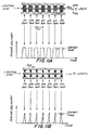
- FIG. 9 This fundamental difference between distributed and non-distributed heat sources is conceptually depicted in FIG. 9 where the flavor delivery profiles from distributed and non-distributed heat sources are compared.
- the flavor delivery to the consumer with non-distributed heat sources varies from puff to puff, in contrast to distributed heat sources where the distributed flavor source is put is thermal contact with the distributed heat source.
- the source of the flavor delivery variation in non-distributed designs is due to the non-constant extraneous material which exists in between the combustion front of the heat source and the flavor source and which acts as an unnecessary heat sink.
- the flavor delivery for each individual puff of the flavor generating article can be precisely controlled.
- the insulating material included in the flavor generating units of the present invention assists in allowing for precise control over the heat transfer characteristics of the flavor generating article.
- the insulating material is chosen as a design parameter.
- the insulator material should be chosen so that the flavor source is exposed to a temperature which would allow the tobacco elements of the flavor source to undergo extensive pyrolysis.
- exposing the flavor source to high temperatures can be accomplished in two (2) alternate ways depending upon the heat source material properties. If the heat source is at a temperature much higher than that needed to produce the necessary extensive pyrolysis in the flavor source, then a thick insulator with a low thermal conductivity can be inserted in between the heat source and the flavor source.
- the heat source is not at such high temperatures, but only at a temperature which is only close to the pyrolysis temperature of the flavor source, then it would be necessary to couple most of the heat that is generated in the heat source directly to the flavor source.
- This can be accomplished by choosing a very thin insulator with high thermal conductivity or possibly even eliminating the insulator material altogether by positioning the flavor source in direct physical contact with the heat source.
- the design parameters of the flavor generating unit include, among others, the temperature of the heat source and the thickness and thermal conductivity of an insulating material positioned in between the heat source and the flavor source, if at all included in the design of the flavor generating unit.
- the insulator material should be chosen so that the flavor source is not exposed to a temperature which would allow the tobacco elements of the flavor source to undergo extensive pyrolysis.
- limiting the exposure of the flavor source to a low temperature can also be accomplished in two (2) alternate ways depending upon the heat source properties. If the heat source is at a temperature much higher than the combustion temperature of the flavor source, then a thick insulator with a low thermal conductivity should be inserted in between the heat source and the flavor source.
- the heat source is not at such high temperatures, but only at a temperature which is close to or lower than the extensive pyrolysis temperature of the flavor source, then most of the heat that is generated in the heat source can be coupled directly to the flavor source without extensive pyrolysis of the flavor source.
- FIGS. 8A and 8B An example of this type of embodiment can be explained with reference to FIGS. 8A and 8B.
- the embodiment of FIGS. 8A and 8B can be programmed to have the first five puffs of the flavor generating unit generate a "rich” smoke while the last four puffs could generate a "lean” smoke.
- the thickness of the insulator under the first five individual flavor source components can be small while the thickness under the last four components can be large.
- the thermal conductivity of the insulator under the first five individual flavor source components can be large while the conductivity under the last four components can be small.
- the combustion temperature of the heat source itself can be designed to be non-uniform down the distributed length of the source.
- the heat source could be designed to have a high combustion temperature under the first five individual flavor source components while under the last four components the combustion temperature could be designed to be small.
- a fourth possibility for producing a high heat source temperature under the first five individual flavor source components and a lower one under the last four would be to incorporate a second insulator material under the back side of the heat source underneath the first five components.
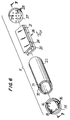
- Flavor generating article 10 consists of an active element 11 and an optional expansion chamber tube 12, overwrapped by cigarette wrapping paper 14, and a filter element 13 attached by tipping paper 205.
- Wrapping paper 14 preferably is a cigarette paper treated to minimize thermal degradation, such as a magnesium oxide, or other suitable refractory type, cigarette paper.
- active element 11 includes a distributed flavor generating unit 26 which includes a distributed heat source 20 and a distributed flavor source 21 which releases flavored vapors and gases when heated.
- distributed flavor generating unit 23 includes an insulating material 24 to further control the heat transfer characteristics of the distributed flavor generating unit 26, as discussed in detail below.
- the vapors generated from flavor source 21 form an aerosol and pass into an optional expansion chamber tube 12 and mouthpiece element 13, and then into the mouth of a" smoker.”
- distributed heat source 20 is substantially rectangular and flat in shape.
- distributed heat source 20 has dimensions of width and length so that flavor generating article 10 has dimensions comparable to the diameter and length of a conventional flavor generating article, such as a cigarette.
- its preferred dimensions should be about 50 mm long, about 7.4 mm wide, and about 2 mm thick.
- Distributed heat source 20 can be fabricated using any of the heat source materials and methods described in detail above.
- flavor source 21 is also substantially rectangular and flat in shape. Its width is comparable to the width of heat source 20 but has a length that is shorter than heat source 20 so as to offset heat source 20 from the flavor source 21. This "offset" exposes an area 206 of heat source 20 so that flavor source 21 does not combust upon lighting of flavor generating article 10. Flavor source 21 can be fabricated using any of the flavor source materials and methods described in detail above.
- heat source 20 will burn to produce mostly carbon dioxide.
- radiant energy reflector sleeve 22 of active element 11 is substantially non-combustible, and does not burn during flavor generating of article 10.
- article 10 is constructed in such a way that flavor source 21 is in thermal contact with distributed heat source 20 so that the temperature that flavor source 21 is exposed to is controlled by the design, geometry, and positioning of distributed heat source 20, flavor source 21 and, if included, insulator material 24.
- the transfer of heat from heat source 20 into flavor source 21 can be can be regulated so that the temperature which flavor source 21 achieves can also be precisely controlled.
- the design and geometry of distributed flavor generator unit 26 can be chosen so that flavor source 21 undergoes either pyrolysis or combustion.
- active element 11 is housed in an inner radiant energy reflector sleeve 22.
- Distributed flavor generator unit 26 is held within inner sleeve 22 along its distributed length.
- Optional expansion chamber tube 12 with its inner sleeve 23 adds to the length of article 10 and thus article 10 has the appearance of an ordinary cigarette.
- Wrapper 14 holds active element 11 and expansion chamber tube 12 together.
- cigarette wrapping paper 14 will have sufficient porosity to allow air to be admitted through paper 14 and radiant energy reflector sleeve 22 to support combustion of heat source 20.
- paper 14 may be perforated, such as by laser perforation, in the region of radiant energy reflector sleeve 22 which surrounds heat source 20.
- aluminum insert 27, fitted in between active region 11 and expansion chamber tube 12, leaves only a plurality of orifices 28 for the passage of the hot vapors. Passage of hot vapors through plurality of orifices 28 causes the vapors to increase their velocity and then expand into expansion chamber tube 12. Expansion of the vapors and gases into the expansion chamber causes cooling of the saturated vapors to form a stable aerosol, thereby minimizing condensation on segments 29 and 200, increasing the delivery of aerosol to the "smoker.” The degree of expansion, and therefore of cooling, may be controlled by varying the size and density of orifices 28 and the volume of expansion chamber 12. Aluminum insert 27 also serves as a heat sink so that radiated and convective heat from heat source 20 does not cause over heating/combustion of the tobacco filler in segment 200, if present, or the cellulose acetate filter plug 201.
- Mouthpiece element 13 may be a hollow tube or may include segment 29. Mouthpiece element 13 preferably includes two segments 29 and 200. Segment 29 is a cellulose acetate filter plug 201 wrapped in plug wrap 202. Segment 200 is a rod of tobacco filler, wrapped in plug wrap 203, which, in addition to further cooling the aerosol and providing some filtration, may impart additional tobacco taste.
- the tobacco filler in segment 200 is preferably cut at the standard thirty (30) cuts per inch, but may be coarser to minimize filtration. For example, the tobacco filler may be cut at about fifteen (15) cuts per inch.
- the two segments 29 and 200 of mouthpiece element 13 are jointly overwrapped by plug wrap 204, and the entire mouthpiece element 13 is attached to the remainder of article 10 by tipping paper 205.
- heat-side space 39 is provided so that there is sufficient air flow to distributed heat source 20 to allow for sustained combustion and so that the amount of heat which is conducted to flavor source 21 is sufficient so as to allow flavor source 21 to achieve its desired temperature.
- radiant energy reflector sleeve 22 is perforated so as to allow air to pass through it.
- the open area and permeability of radiant energy reflector sleeve 22 should be large enough so that the permeability of air and oxygen through the composite of wrapping paper 14 and radiant energy reflector sleeve 22 is limited and controlled by the permeability of wrapping paper 14. Under these conditions, it would be mainly the permeability of wrapping paper 14 that would determine the mass burn rate of distributed heat source 20.
- the permeability of the combination of sleeve 22 and wrapping paper 14 would be a function of the individual permeabilities of sleeve 22 and wrapping paper 14 and would not be limited by permeability of wrapping paper 14.
- article 10 which ever air permeability design is chosen, it is desirable for article 10 to provide about ten (10) puffs under FTC conditions (i.e.,a two-second, thirty-five milliliter puff taken once a minute). If the mass burn rate of distributed heat source 20 is too high, each puff taken by a "smoker" will deliver added flavor because the amount of heat reaching distributed flavor source 21 will be enhanced. This enhancement occurs as a result of distributed heat source 20 emitting heat over a broader area than with smaller mass burn rates. As a result of this broader area of emission of heat, distributed flavor source 21 will also generate flavor over a broader area. Since more of heat source 20 is consumed in each puff, heat source 20 may be consumed in fewer than ten (10) puffs.
- radiant energy reflector sleeve 22 can be made from metallized paper. More preferably, as seen in FIGS. 6 and 7, radiant energy reflector sleeve 22 is made up of a paper layer 70 and inner foil layer 71. Foil layer 71 reflects heat radiated by heat source 20 to keep it hot and thus to ensure that it does not cool down below its ignition temperature and become extinguished.
- Paper layer 70 may be made by spiral winding a paper strip or using other well-known techniques of paper tube making. Preferably, however, paper layer 70 and foil layer 71 are passed together through a garniture, similar to that used in the making of conventional cigarettes, which forms them into a tube. In that preferred embodiment, the edges of paper layer 70 is either porous or perforated, so that the required permeability, referred to above, can be achieved.
- Foil layer 71 is preferably made by taking a standard 1 to 10 mil aluminum foil, embossing it to provide raised holes, and then calendaring it to flatten the holes so that the perforated foil is more nearly smooth. Although calendaring closes up the holes somewhat, the desired permeability can be achieved by taking this effect into account when the foil is embossed.
- foil layer 71 reflects a substantial portion of the heat produced by heat source 20, some of the heat may be absorbed and therefore will be conducted through foil layer 71 to paper layer 70. For that reason, the paper used in paper layer 70 preferably is modified to prevent combustion so that it does not ignite when article 10 is "smoked." Furthermore, if desired, paper layer 70 can also include (not shown in figures) up to three layers of a paper treated to reduce thermal degradation, such as magnesium oxide, or other suitable refractory type, cigarette paper.
- radiant energy reflector sleeve 22 can be comprised of a single perforated aluminum sleeve. Its inside walls should be reflectorized so that its ability to reflect heat is maximized.
- Air chamber 12 includes air chamber sleeve 23 which preferably is not perforated. It can be constructed out of heavy paper or the same material which radiative energy reflector sleeve 22 is made of. Since the inner walls of air chamber sleeve 23 are not exposed directly to heat source 20, it is less critical that air chamber sleeve 23 has to be designed with thermal degradation considerations in mind, in contrast to radiant energy reflector sleeve 23.
- active element 11 is provided with a reflective end cap 15 which clips into radiant energy reflector sleeve 22 but is covered by wrapper 14.
- Cap 15 has one or more opening 16 which allow air into active element 11. Opening 16 preferably is located at the periphery of cap 15. In the preferred embodiment, there are six equiangular spaced openings 16 each having a diameter of eighty (80) mils.
- Cap 15 increases the reflection of radiation back into active element 11, and also keeps heat source 20 from falling out of article 10 if it somehow becomes lose. This is important when it is considered that heat source 20 smolders at a high temperature between puffs, and is even hotter during puffs. Cap 15 also keeps in any ash that may form during burning of heat source 20.
- article 10 have an outer diameter of about 7.9 mm, similar to a conventional cigarette.
- Heat source 20 preferably has a width of about 7.4 mm and a length of about 40 mm, while active element 11 preferably has an overall length of about 50 mm.
- Mouthpiece element 13 preferably has a length of 21 mm, divided between a 10 mm cellulose acetate filter portion segment 29 and an 11 mm tobacco rod portion segment 200.
- Expansion chamber tube 12 preferably is about 29 mm long, so that article 10 overall is about 100 mm long, which is comparable to a conventional "long-size" cigarette.
- FIGS. 1-7 has a distributed flavor generating unit 26 with a single continuous distributed flavor source 21 which sits on top of a single continuous distributed insulator material 24, if such a material is included in the design of article 10.
- the distributed flavor source can be comprised of a plurality of individual flavor source components. In such an embodiment each individual charge represents one puff of the article.
- FIGS. 8A and 8B where the distributed flavor generating unit 226 is comprised of single continuous distributed heat source 220, single continuous distributed insulator material 224 of width W IN and a plurality of individual flavor source components 221 with a contact width of W CA .
- This embodiment also has an "offset" area 299 on the ignition end of heat source 220 so that the first flavor source charge 221 closest to the ignition end of distributed flavor generating unit 226 does combust upon lighting of flavor generating article 10.
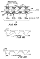
- FIG. 10A Another preferred embodiment of a flavor generating article according to the present invention is shown is FIG. 10A.
- the figure only shows a portion of a flavor generating article, active element 311.
- active element could be incorporated into the flavor generating article depicted in FIGS. 1-7 above, which were described in detail.
- Active element 311 includes distributed continuous flat heat source 320, distributed flavor source 321, flavor source holder 331 and perforated sleeve 322.
- distributed heat source 320 is substantially rectangular in shape as in heat source 21 of FIGS. 1-7.
- distributed heat source 320 has dimensions of width and length so that the flavor generating article in which it is incorporated has dimensions comparable to the diameter and length of a conventional flavor generating article, such as a cigarette. Its preferred dimensions should be about 50 mm long, about 7.4 mm wide, and about 2 mm thick.
- Distributed heat source 320 can be fabricated using any of the heat source materials and methods described in detail above.
- distributed flavor source 321 is comprised of a plurality of individual flavor source components. These individual components can exist on one side of heat source 320, as was the case for the embodiment depicted in FIGS. 8A-8B, or can exist on both sides of distributed heat source 321, as depicted in FIG. 10A.
- the flavor source material that the individual components are composed of can be chosen from any of the flavor source materials described in detail above, but preferably the components are composed of pelletized tobacco, as discussed above.
- FIG. 10A depicts a plurality of "air gaps" 324 in between heat source 320 and flavor source holder 331. These air gaps serve the same purpose that the insulator 24 serves in the embodiment of FIGS. 1-7.
- the function of the insulating air gap is to control and regulate the heat transfer properties of the flavor generating unit of the flavor generating article. As discussed in detail above, larger insulator thicknesses (i.e., larger air gaps) reduce the temperature that the flavor source is exposed to, and consequently reduce the potential for combustion of the tobacco elements in the flavor source.
- larger insulator thicknesses i.e., larger air gaps
- the size of the air gap (i.e., the thickness of the insulator substance) can be reduced to zero by simply allowing flavor source material 321 to come into direct contact with heat source 320.
- This type of design can be achieved by simply eliminating that portion of flavor source material holder 331 that exists adjacent to the insulating air gap 324.
- FIGS. 10B and 10C show two possible embodiments of flavor source holder 331 where the size of the insulating air gap is zero (i.e., flavor source material is in direct physical contact with the heat source).
- FIG. 10B shows an embodiment with perforations in side wall 332 of flavor source holder 331B.
- FIG. 10C shows an embodiment without perforations in side wall 333 of flavor source holder 331C.
- Both figures include perforated sleeve 322 which preferably has a permeability so large that when the sleeve is incorporated into a flavor generating article similar to that in FIGS. 1-7, the permeability of the outer wrapping paper (14 in FIGS. 1-7) will limit the permeability of the composite structure.
- flavor source holder 321 The presence or absence of perforations in flavor source holder 321 will influence flavor delivery to the consumer.
- the density of perforations should be chosen so that flavor delivery is optimized, depending upon the specific geometry and materials of which active element 311 are composed. Since the perforation density will also influence the mass burn rate of heat source 320, the specific optimized density will also depend upon the structure of heat source 320.
- One of ordinary skill in the art would adjust the perforation density of flavor source holder 331 in the same manner that the permeability is adjusted in the composite wrapping paper and outer sleeve in other forms of flavor generating articles.
- Flavor source holder 331 and perforated sleeve 322 can be formed of thermally stable paper treated to minimize thermal degradation as discussed above with respect to the embodiment depicted in FIGS. 1-7, or more preferably, can be formed from aluminum preferably about 1 to 2 mils thick.
- the width of the contact area of the flavor source holder (labelled W CA in FIG. 10A) facing heat source 320 can also be varied in addition to the "air gap" between the heat source and flavor source.
- This aspect of the present invention is depicted in FIGS. 11A and 11B, where embodiments with a large and a small contact area, respectively, are shown. Included in FIGS. 11A and 11B are conceptual flavor delivery profiles associated with the flavor generating units.
- a flavor source holder with a larger width of contact area, W CA is shown.
- FIG. 11A a flavor source holder with a larger width of contact area, W CA , than in FIG. 10A is shown.
- the width of contact area has been reduced to a point where the pellets of the flavor source do not come into direct physical contact with the distributed heat source.
- extensive pyrolysis of the flavor source pellets closest to the heat source is less likely in the design of FIG. 11B in comparison to the designs of FIGS. 10A-10C and 11A.
- reducing the width of the contact area serves the same purpose as inserting an insulator in between the flavor source and heat source: to control and regulate the heat transfer properties of the flavor generating unit and to reduce the temperature that the majority of the flavor source material is exposed to.
- a second aspect of the effect of varying the width of the contact area of the present invention is that it allows the quantity of flavor delivered to the consumer in a single puff to be precisely controlled.
- This added benefit of the present invention is conceptually depicted underneath the embodiments of the flavor generating units in FIGS. 11A and 11B, where delivery of flavor to the consumer is plotted against time as the combustion front moves down along the distributed heat source in the D CF direction.
- the total delivery of flavor is smaller than with larger contact areas (i.e., larger contact times), as shown in FIG. 11A.
- FIGS. 10A, 11A and 11B show how the design of the flavor source holder can be varied in an embodiment of a flavor generating article of the present invention with a distributed continuous flat heat source.
- the distributed heat source can be cylindrical.
- FIGS. 12A-12C Such an embodiment is shown in FIGS. 12A-12C, where, analogously with FIGS. 10A, 11A and 11B, the width of the contact area, W CA , is also varied.
- the inner radius of cylindrical heat source 420 should be designed in the same manner that the heat source of the other embodiments of the present invention are designed.
- the inner heat space 439 should be large enough so that sufficient oxygen is present inside cylindrical heat source 420 so that the heat source does not extinguish in between puffs. Furthermore, it should not be so large that the propagation of the combustion front down heat source 420 is too fast.
- FIGS. 13A and 13B Further embodiments of the present invention are shown in FIGS. 13A and 13B where flat-ladder-type of distributed heat sources are depicted.
- active element 511 includes distributed flat-ladder heat source 520 and perforated sleeve 522.
- Flat-ladder heat source includes left leg 520B and right leg 520A. These two legs are connected by rung 520STP.
- FIG. 13B depicts four embodiments (I, II, III and IV) of the cross section of rung 520STP along line A-A of FIG. 13A.
- rung 520STP includes left leg 520B and right leg 520A which are connected by heat source rung 520C.
- these three components comprise a one-piece heat source, as opposed to a heat source where parts 520B, 520A and 520C are attached together after fabrication of the individual parts. Included on one side of heat source rung 520C is individual flavor source charge 521.
- heat source rung 520C is bounded on one side with individual flavor source charge 521 and on the opposite side with individual insulator material 524 of width W IN .
- the insulator material serves the same purpose of regulating and controlling the heat transport properties of the flavor generating unit as did the insulator material in FIGS. 1-8 and the "air gap", in the discussion surrounding FIGS. 10-12 above.
- heat source rung 520C is bounded on both sides with flavor source material: on the top side of the rung is individual flavor source charged 521A, while on the opposite side is individual flavor source charge 521B.
- heat source rung 520C includes individual flavor source charge 521 which is separated from the rung by individual insulator material 524 of width W IN .
- FIGS. 14A-14C Another embodiment of the present invention is shown in FIGS. 14A-14C.
- This embodiment includes distributed cylindrical heat source 620, distributed mono-layer flavor source 621, flavor source holder 631 and perforated sleeve 622.
- Distributed flavor source 621 is in thermal contact with distributed cylindrical heat source 620.
- An air gap 624 of width W IN between heat source 620 and flavor source 621 serves the purpose of an insulator so as to control and regulate the transfer of heat to flavor source 621 from heat source 620.
- FIG. 14B is a cross section of FIG. 14A at A-A
- FIG. 14C is a cross section of FIG. 14A at B-B.
- flavor source 621 comprises a thin mono-layer of flavor source pellets where the distance of separation between perforated sleeve 622 and insulating air gap 624 is small. Such a thin layer results in extremely efficient heat transfer from the heat source to the outer edge 621E of flavor source 621 and therefore a higher quality puff.
- a 7 mm wide, 60 mm long, 0.30mm thick carbon heat source was coated with a calcium carbonate paste.
- the paste was prepared by mixing 2% CMC (carboxymethyl cellulose), 40% CaCO3, and 58% water. The paste was coated and after drying was 0.38 mm thick and 3 mm in width along the length of the carbon heat source.
- a tobacco mixture composed of 6.2% glycerin, 1.2% pectin, 2.4% wheat starch, 31.5% tobacco and 58.5% water was coated over the CaCO3 surface and dried. The laminated structure was ignited and the heat transfer to the tobacco was sufficient for generation of an aerosol without combustion of the tobacco.
- the distributed flavor source may be a continuous cylindrical and monolayer flavor source.
Abstract
A flavor generating unit (26) for incorporation into a flavor generating article (10) which delivers to a consumer an inhalable flavor-containing substance. The flavor generating unit includes a distributed heat source (20) and a distributed flavor source (21) in thermal contact with the distributed heat source. The flavor generating unit can also include an insulating material (24). Furthermore, the distributed flavor source can be composed of one or more individual flavor source components.
Description
- This invention relates to flavor generating articles which deliver flavor to the consumer during each individual puff of the article.
- A substantial number of previous attempts have been made to produce a flavor generating article in which the quality of flavor delivery resembles that achieved in conventional cigarettes without the generation of sidestream smoke. Accordingly, a wide variety of various design geometries have been tried in an attempt to mimic the quality of flavor delivery in conventional cigarettes. For example, Siegel U.S. Patent No. 2,907,686 describes a smoking article consisting of a charcoal rod and a separate carrier impregnated with flavorants and a synthetic "smoke" forming agent which is heated by the burning charcoal rod. The charcoal rod is coated with a concentrated sugar solution so as to form an impervious layer during burning. It was thought that this layer would contain the gases formed during flavor generating and concentrate the heat thus formed.
- Another smoking article, described in US - A - 3,258,015, employs burning tobacco in the form of a conventional cigarette to heat a metallic cylinder containing a source of nicotine, such as reconstituted tobacco or tobacco extract. During flavor generating, the vapors released from the material inside the metal tube mix with air inhaled through an open end of the tube which runs to the burning end of the flavor generating article.
- US - A - 3,356,094 describes a similar flavor generating article in which the tube becomes frangible upon heating, so that it would break off and not protrude when the surrounding tobacco had burned away.
- Our EP - A - 0 177 355 describes a smoking article which produces a nicotine-containing aerosol by heating, but not burning, a flavor generator. The flavor generator could be fabricated from a substrate material such as alumina, natural clays and the like, or tobacco filler. The flavor generator is impregnated with thermally releasable flavorants, including nicotine, glycerol, menthol and the like. Heating of the flavor generator is provided by hot gases formed as a result of the combustion of a fuel rod of pyrolized tobacco or other carbonaceous material.
- US - A - 4,714,082 shows a variation of the Hearn et al. article which employs a fuel element. The performance of the article is said to be improved by maximizing heat transfer between the fuel element and the aerosol generator. This is effected by preventing heat loss by insulation, and by enhancing heat transfer between the burning fuel and the flavor generator by a metallic conductor. A spun glass fiber insulator surrounds the fuel element and aerosol generator assembly.
- Our US - A - No. 4,991,606 describes a flavor generating article wherein the flavor bed is positioned relative to the heat source so that heat transfers from the heat source to the flavor bed by radiation and convection. Such a design produces substantially no visible sidestream smoke. Further improvements on such a design can be achieved with the incorporation of improved heat sources. For example, Our EP - A - 0 372 985 describes a heat source made of iron carbide. Such a heat source produces virtually no carbon monoxide upon combustion. Furthermore, our EP - A - 0 430 658 describes a heat source made of metal nitride that produces virtually no carbon monoxide or nitrogen oxide. Thus, flavor generating articles with substantially no visible sidestream smoke and which produce virtually no carbon monoxide or nitrogen oxide can be produced.
- Although a wide variety of flavor generating article geometries have been tried, the flavor generating articles described above suffer from a number of design-related drawbacks which have prohibited the flavor generating articles from producing a constant quality of flavor delivery. In the above flavor generating articles, the flavor source is arranged in a geometry where it is concentrated into a single three-dimensional "chamber" with the diameter and length of the chamber approximately the same as the diameter of the flavor generating article. Analogously, the heat source, which is also concentrated into its own individual "chamber," is also arranged with a geometry similar to the flavor source. These two individual "chambers" are then butted against each other so that the heat which is generated in the heat source "chamber" can transfer into the flavor source "chamber." Such a design has inherent disadvantages which have contributed to its inability to mimic the constant quality of flavor delivery obtained in conventional cigarettes.
- First, since the "chambers" necessarily have dimensions on the order of the diameter of the flavor generating article, heat that is generated in the heat source must at times be transferred up to distances on the order of twice the diameter of the flavor generating article in order to heat the flavor source material that is most remote from the heat source. Because this distance can be large, the heat transfer properties of the article are inefficient. The large mass of material over which the heat must transfer serves as an unnecessary heat sink. As a result, the heat source of these devices is inefficient since it must generate more heat than a heat source in a structure where heat would not have to be transferred over large distances.
- Second, since large heat transfer distances are involved, large transients also exist in the heat transfer properties which result in non-uniformity in the quality of the individual puffs of the article over its lifetime. Once the heat source generates heat in a localized region of the heat source "chamber," it takes time to be transferred to the flavor source where it can heat it up so as to produce smoke-like vapors and aerosols. As a result, the quality of the first few puffs of such articles is inferior to the quality of the third and fourth. Furthermore, because large heat transfer distances are involved, the transfer of heat from the heat source to the flavor source during a puff is inherently slow and thus results in an inferior quality puff.
- Third, because the heat transfer distance varies for each puff of the flavor generating article it is difficult to provide constant flavor delivery over each puff of the flavor generating article. For example, during the ninth and tenth puff, there is a large quantity of "flavor-depleted" flavor source material which serves as an unnecessary heat sink. This results in a degradation in the quality of the puff. Such degradation is an inherent quality of flavor generating articles which have a heat source "chamber" butted against a flavor source "chamber." The regulation of flavor delivery in these type of flavor generating articles is controlled by the smoker. If such a flavor generating article is "puffed" at high volumes, depletion of flavors occurs early -- resulting in inferior quality later puffs.
- It would be desirable to be able to provide a flavor generating article which does not produce sidestream smoke but which does not suffer from the inherent design drawbacks exhibited by the articles discussed above.
- It is an object of this invention to provide a flavor generating article which produces substantially no visible sidestream smoke and where the delivery of flavor to the consumer during each individual puff of the article can be precisely controlled and regulated.
- In accordance with this invention, there is provided a flavor generating article capable of producing a substantially constant quality of flavor delivery from the first to last puff of the article, as is obtained in conventional cigarettes. This ability of the present invention is achieved for the first time because a distributed flavor source is placed in thermal contact with a distributed heat source. Such a design allows for the heat to be directly transferred by conduction and convection from the heat source to the flavor source.
- Preferred embodiments have a flavor generating unit which is comprised of a distributed heat source, a distributed flavor source and an optional insulating material. The distributed flavor source is in thermal contact with the distributed heat source. Because of the distributed nature of the heat and flavor sources and because they are in thermal contact with each other, the present invention allows the quality of the individual puff to be precisely controlled and regulated. Accordingly, the present invention can produce the same flavor delivery, which is constant from puff to puff, as is obtained in conventional cigarettes.
- The above and other objects and advantages of the invention will be apparent upon consideration of the following detailed description, taken in conjunction with the accompanying drawings, in which like reference characters refer to like parts throughout, and in which:
- FIG. 1 is an exploded perspective view of a first preferred embodiment of a flavor generating article according to the present invention;
- FIG. 2 is a longitudinal cross-sectional view of the flavor generating article of FIG. 1, taken from line 2-2 of FIG. 1;
- FIG. 3 is an end view of the flavor generating article of FIGS. 1 and 2, taken from line 3-3 of FIG. 2;
- FIG. 4 is a radial cross-sectional view of the flavor generating article of FIGS. 1-3, taken from line 4-4 of FIG. 2;
- FIG. 5 is a radial cross-sectional view of the flavor generating article of FIGS. 1-4, taken from line 5-5 of FIG. 2;
- FIG. 6 is an exploded perspective view of the active element of the flavor generating article of FIGS. 1-5;
- FIG. 7 is a longitudinal cross-sectional view of the active element of the flavor generating article of FIGS. 1-6 taken from line 7-7 of FIG. 6;
- FIG. 8A is a side view of a distributed flavor generating unit with a plurality of individual flavor source components which can be incorporated into the flavor generating article of FIGS. 1-7;
- FIG. 8B is a perspective view of the distributed flavor generating unit of FIG. 8A;
- FIG. 9 is a conceptual comparison between distributed and non-distributed heat sources of flavor delivery profiles;
- FIG. 10A is a side view of a distributed continuous flat heat source with a plurality of individual flavor source components distributed on both sides of the heat source;
- FIG. 10B is a side view of an embodiment of a perforated mounting structure of FIG. 10A;
- FIG. 10C is a side view of an embodiment of a non-perforated mounting structure of FIG. 10A;
- FIG. 11A is a side view of a distributed continuous flat heat source where the width of the flavor source contact area with the heat source is larger than in the embodiment of FIG. 10A; also included is an associated conceptual depiction of flavor delivery versus time as the combustion front moves down along the distributed heat source in the DCF direction.
- FIG. 11B is a side view of a distributed continuous flat heat source where the width of the flavor source contact area with the heat source is smaller than in the embodiments of FIGS. 10A and 11A; also included is an associated conceptual depiction of flavor delivery versus time as the combustion front moves down along the distributed heat source in the DCF direction.
- FIG. 12A is a side view of a distributed continuous cylindrical heat source with a plurality of individual flavor source components distributed around the heat source;
- FIG. 12B is a side view of a distributed continuous cylindrical heat source with a plurality of individual flavor source components distributed around the heat source and where the width of the flavor source contact area with the heat source is larger than in the embodiment of FIG. 12A;
- FIG. 12C is a side view of a distributed continuous cylindrical heat source with a plurality of individual flavor source components distributed around the heat source and where the width of the flavor source contact area with the heat source is smaller than in the embodiments of FIGS. 12A and 12B;
- FIG. 13A is a top view of a distributed flat-ladder type of heat source with a plurality of individual flavor source components distributed on the rungs of the ladder;
- FIG. 13B is a cross-sectional view of four embodiments (I, II, III, and IV) of the rungs of FIG. 13A taken along line A-A;
- FIG. 14A is a side view of a distributed continuous cylindrical heat source with a distributed "mono-layer" flavor source;
- FIG. 14B is a radial cross-sectional view of the flavor generating article of FIG. 14A, taken from the line A-A of FIG. 14A; and
- FIG. 14C is a radial cross-sectional view of the flavor generating article of FIG. 14A, taken from the line B-B of FIG. 14A.
- The basic flavor generating article of the present invention includes a distributed flavor source in thermal contact with a distributed heat source. When the heat source heats the flavor source, flavor-containing substance (i.e., a vapor or aerosol, or mixture thereof, containing flavored vapors or aerosols or other vapors or aerosol components) is generated or released from the flavor source and can be drawn in by the consumer. As used herein, "thermal contact" means that the distributed boundaries of the flavor source and heat source are adjacent each other and not necessarily in direct physical contact.
- The flavor source can be any material that can be distributed and placed in thermal contact with the distributed heat source of the present invention and which, when heated, releases a flavor-containing substance. Such materials can include as a component tobacco, reconstituted tobacco, tobacco condensates (condensed components of the smoke produced by the combustion of tobacco, leaving flavors and, possibly, nicotine), or tobacco extracts. These materials when heated generate or release a flavor-containing substance (which may include nicotine) which can be drawn in by the consumer. Any of these flavor generating materials can also include an aerosol-forming substance (i.e., aerosol precursor), such as glycerin, propylene glycol, 1,3-butanediol, water or the like. These materials give the "smoker" the perception of inhaling and exhaling "smoke" as in a conventional cigarette where tobacco is burned.
- A particularly preferred flavor source material is a composition such as that described in our EP - A - 0 352 107 which describes pelletized tobacco containing an aerosol-forming ingredient and a filler. This composition can be used in the pellet form or, instead of being formed into pellets, could be deposited as a sheet or coating, in conjunction with adhesion agents such as pectins, gums, or cellulose derivatives, such as carboxymethyl cellulose (CMC), or the like. If this sheet or coating-type of flavor source material is used, then the material is applied as a sheet or coating to the heat source. In such a flavor source, the pellets should have a size in the range of approximately 0.1 mm to approximately 0.5 mm. The flavor source material may also be applied to an inert insulating substrate in contact with the heat source, if such an insulating material is used in the flavor generating article design.
- The tobacco pellets described above are preferably formed by combining in an extruder: particularized tobacco materials, having a size of from about 20 mesh down to about 400 mesh, preferably, about 150 mesh, an aerosol-forming material (i.e., an aerosol precursor, such as, glycerin, 1,3-butanediol or propylene glycol), that can be widely dispersed among the tobacco particles, and a finely divided filler material, for example, calcium carbonate or alumina, to increase the thermal load to prevent the heat source from raising the temperature of the pellets above their thermal decomposition temperature. The materials are mixed to form a mixture, and the mixture is extruded out a die typically having a plurality of orifices into spaghetti-like strands of about the same diameter. The extruded strands are cut into lengths, preferably of uniform length. The pellets preferably are uniformly dimensioned and comprise a mixture of about 15% to about 95% tobacco material, about 5% to about 35% aerosol precursor, and about 0% to about 50% filler material.
- Another preferred flavor source material is a gel-based composition such as that described in our copending European application No. 92 302 592.8, which describes a gel-based flavor source containing glycerin (as an aerosol-forming ingredient), tobacco particles, and a gelling agent (to supply structural rigidity to the flavor source). When used in the present invention, instead of being formed into a one-piece central cylinder from which a plurality of vanes radiate outward in a spoke-like fashion, the gel-based composition would be formed into a "sheet" or some other distributed shape so that it can be positioned in thermal contact with the distributed heat sources of the present invention.
- Other flavor source materials are also contemplated by this invention. For example, the flavor source could be a reconstituted tobacco sheet made from a combination of tobacco dust with a binder or the like. Furthermore, the flavor source could also be a material that can be "sprayed" onto the heat source or onto the inert insulating substrate in contact with the heat source. In this later type of process the flavor source material is sprayed on while it is in a liquid-like state and then is allowed to dry or harden so that it adheres to the flavor generating unit. What ever type of flavor source is employed in the flavor generating article of the present invention, the only restriction on the flavor source is that it must be able to be placed in thermal contact with the heat source.
- In some embodiments of the present invention, as discussed below, the flavor source material is divided into individual components, each representing one puff of the flavor generating article. In such designs it is possible to mimic a conventional cigarette by providing the number of components of flavor source material equal to an average number of puffs per cigarette, e.g., eight to ten puffs. Although the flavor generating article does not decrease in length like a conventional cigarette as it is consumed, it is possible to make the flavor generating article in varying lengths, with a different numbers of puffs.
- As discussed above, the flavor source can be any material that can be placed in thermal contact with the distributed heat source and which, when heated, releases a flavor-containing substance for inhalation by the "smoker". Analogously, the heat source of this invention can be any material that can be formed into a distributed shape and which would undergo an exothermic reaction to liberate heat so as to enable the flavor generating material to release flavor-containing substances.
- Preferably, the heat source should combust to produce substantially no carbon monoxide or nitrogen oxides. Preferred materials for the heat source include carbon, metal carbides, metal nitrides, metal oxides and metals. More preferable materials are carbon, non-stoichiometric metal nitrides, metal oxides, or mixtures thereof. Most preferably, the heat source comprises materials made according to the methods of any one or more of our EP-A-0 352 108, 0 372 985, 0 430 658, 0 467 658, 0 494 784 and European Application No. 92 304 310.3 filed July 19, 1991.
- Any method capable of forming the heat source into the desired distributed shape may be used. Preferred methods of manufacture include, but are not limited to, slip casting, injection molding, die compaction and extrusion. Those skilled in the art will understand that a particular desired distributed shape may require a particular method of manufacture. The heat sources may be prepared at the desired size and shape or alternatively, they may be cut, shaped or otherwise produced from a larger piece of material. Furthermore, precursors to the desired heat source materials listed above may be formed into the desired shape and then converted, in situ, to the desired materials.
- In addition to the distributed heat source and the distributed flavor source, the flavor generating units of the present invention may optionally include, as discussed below, an insulator material or substance. Its purpose is to further regulate the generation and conduction of heat reaching the flavor source. A thermal insulation material, as employed herein, is any substance or configuration of materials that resists the flow of heat. Preferably, the insulation material or substance should have a low density so that it does not absorb too much heat and act as a heat sink. Alternatively, the insulation material or substance can be porous in order to avoid the absorption of heat. The insulation materials of the present invention do not stop heat flow, but simply retard it to a rate that suits a particular design requirement. These materials include, preferably, ceramics and more preferably, alumina. A most preferred insulating material is calcium carbonate. Any method capable of forming the insulating material into a shape so that it can be brought into thermal contact with the distributed heat source may be used. Those skilled in the art will understand that a particular desired heat source shape may require a particular method of manufacturing the insulating material.
- Those skilled in the art will understand that when a particular embodiment of the present invention requires that the flavor source is directly adhered to the heat source (or to an insulating material) that any adhesion technique suitable for use in the art of flavor generating articles can be employed. The only requirement on the adhesion technique is that the adhesive must be able to bring the flavor source in intimate contact to the heat source (or the insulating material). Of course, preferably, the heat transport properties of the adhesive should be taken into account when the flavor generating article is designed.
- With the above discussion of the fabrication of the distributed heat and flavor source materials and the optional insulating materials, the general theory of operation of the flavor generating article in which they are incorporated into will now be discussed. Furthermore, the advantages of the new design of the present invention over previous designs will also be discussed.
- The flavor generating articles of the present invention include a flavor generating unit. This unit is labelled 26 in the embodiment of FIGS. 1-7 and 226 in the embodiment of FIGS. 8A-8B. The flavor generating units in these embodiments include a distributed heat source (20 in FIGS. 1-7 and 220 in FIGS. 8A-8B), a distributed flavor source (21 in FIGS. 1-7 and 221 in FIGS. 8A-8B), and an optional insulating material (24 in FIGS. 1-7 and 224-in FIGS. 8A-8B). Upon combustion of the distributed heat source, heat is generated and is then partially transferred through the insulating material (24, 224) to the distributed flavor source (21, 221) where flavor-containing substance is generated and released for consumption by the smoker.
- In the present invention, because the heat source is distributed, the heat transfer properties of the flavor generating article can be regulated and controlled so as to improve the flavor delivery characteristics in each individual puff of the article in comparison to flavor generating articles which employ a non-distributed flavor "bed" that is physically separated from a non-distributed heat source chamber.
- Furthermore, in the present invention, the heat that is produced in a localized region of the distributed heat source undergoes transport in at least two distinct spacial directions. Such multi-dimensional heat transport, in contrast to uni-dimensional transport, allows the flavor source of the present invention to be heated quicker, more directly and more controllably than flavor generating articles without such "distributed" heat sources. The ability to employ multi-dimensional transport is a direct result of the distributed nature of the flavor generating units of the present invention.
- In contrast to previous flavor generating article designs, the present invention utilizes heat transfer in two distinct directions. In one of these directions the combustion front of the heat source propagates down along the heat source (i.e., down along the distributed length of the source). This direction is labelled "DCF" in FIGS. 1-7 and 8A-8B. The length of time that the combustion front takes to propagate down the distributed heat source determines the useful lifetime of the flavor generating article. In a second direction distinct from the combustion front direction, heat that is generated in a localized region of the distributed heat source is transported to the distributed flavor source, which is in thermal contact with the distributed heat source. This direction is labelled "DFS" in FIGS. 1-7 and 8A-8B.
- The beneficial aspects of the present invention are achieved because the distance of separation between the combustion front in the heat source and the flavor source can be small, fixed, and the same for each individual puff of the flavor generating article. This is in contrast to flavor generating articles which employ a non-distributed flavor "bed" which is physically separate from a non-distributed heat source. In such non-distributed designs, the distance of separation between the localized region of the heat source that is undergoing combustion for a given puff and the localized region of the flavor bed that is generating flavor for that puff is large, not fixed, and not the same for each individual puff of the flavor generating article. The distance of separation is referred to as "large" because sandwiched in between the combustion front of the heat source and the flavor bed are two types of "extraneous" material which are not needed for generating the flavor in a given puff of the flavor generating article.
- The first type of "extraneous" material is heat source material which has not undergone combustion because the combustion front of the heat source, for all but the last few puffs of the flavor generating article, has not propagated throughout the source. There will be more volume and mass of this type of material during the early puffs of the flavor generating article. Because this type of material has not undergone combustion for the majority of puffs of the flavor generating article, and because it is positioned in between the combustion front of the heat source and the flavor bed, it is an unnecessary heat sink. In order to heat up the flavor bed to a given temperature so that it can emit flavor-containing substance, this extraneous region in the flavor generating article must also be heated up with no beneficial results. Consequentially, the heat output of the heat source must be larger than would otherwise be required. This disadvantage exists in a non-distributed design because the heat transport characteristics of the flavor generating article are uni-dimensional since DCF and DFS are in the same direction.
- With the distributed heat source design of the present invention, where DCF and DFS are in two distinct directions, the unnecessary non-combusted heat source material, which existed in the non-distributed designs, has been eliminated. In distributed designs, a distributed flavor source is placed in thermal contact with a distributed heat source. As such, the distance of separation between the combustion front of the heat source and the localized region of the flavor bed that is at a sufficient temperature to emit flavor-generating substance is generally small, fixed, and constant for each individual puff of the flavor generating article. Because of such design, the heat transfer mechanism that is used to heat the flavor source can be predominately conductive. In contrast, in non-distributed designs, convective heat transfer plays a dominant role in heating the flavor source since the distance of separations are necessarily larger.
- The second type of "extraneous" material that is sandwiched in between the combustion front of the heat source and the flavor bed, in non-distributed designs, is flavor source material that has been "depleted" of flavor. This type of material is flavor source material which has been heated for so long that its capability to further emit flavor-containing substance has been reduced to a point where it is not significantly contributing to total volume of flavor and aerosol that the consumer is flavor generating. Such material will exist close to the heat source and will increase in volume with each puff as the flavor generating substance is depleted. As was the case with the extraneous non-combusted heat source material discussed above, this depleted flavor source is also positioned in between the combustion front of the heat source and the localized regions in the flavor bed that are emitting flavor-containing substance. As such, it is also an unnecessary heat sink. In order to heat up "un-depleted" flavor source material to a given temperature so that it can emit significant amounts of flavor-containing substance, this extraneous material in the flavor generating article must also be heated up for no beneficial reasons. Consequentially, the heat output of the heat source must be larger than would otherwise be required. As discussed above, this disadvantage exists in non-distributed designs because the heat transport characteristics of the flavor generating article are uni-dimensional since DCF and DFS are in the same direction. In contrast to the extraneous material associated with the heat source, there will be more of the second type of extraneous material during the later puffs of the flavor generating article. This second type of extraneous material is responsible for the degradation in quality during the last few puffs of the article.
- The fact that there is extraneous material (i.e., non-combusted heat source material and depleted flavor source material) which acts as an unnecessary heat sink is not as much of a problem as the fact that the volume and mass of it is not constant over the lifetime of the flavor generating article. The amount of extraneous material, in non-distributed designs, varies from the first puff of the flavor generating article to the fifth puff and further to the last puff. As a result, the relative delivery of flavor to the consumer varies from the first to the fifth to the last puff of the flavor generating article. In contrast, with the distributed design of the present invention, the amount of material in between the heat source and the flavor source can be fixed and constant for each individual puff. This fundamental difference between distributed and non-distributed heat sources is conceptually depicted in FIG. 9 where the flavor delivery profiles from distributed and non-distributed heat sources are compared. As seen in FIG. 9, the flavor delivery to the consumer with non-distributed heat sources varies from puff to puff, in contrast to distributed heat sources where the distributed flavor source is put is thermal contact with the distributed heat source. As discussed above, the source of the flavor delivery variation in non-distributed designs is due to the non-constant extraneous material which exists in between the combustion front of the heat source and the flavor source and which acts as an unnecessary heat sink. The rise in relative delivery depicted in FIG. 9 during the first few puffs of the non-distributed design, as discussed above, is associated with extraneous heat source material. In contrast, the fall-off in relative delivery depicted in FIG. 9 during the last few puffs of the non-distributed design is associated with the extraneous "depleted" flavor source material.
- Because of the distributed nature of the heat sources of the present invention, the flavor delivery for each individual puff of the flavor generating article can be precisely controlled. The insulating material included in the flavor generating units of the present invention assists in allowing for precise control over the heat transfer characteristics of the flavor generating article. The insulating material is chosen as a design parameter.
- For example, if it is desired to produce a particular puff of smoke which is "rich" or has "full flavor" as in conventional flavor generating articles, then the insulator material should be chosen so that the flavor source is exposed to a temperature which would allow the tobacco elements of the flavor source to undergo extensive pyrolysis. In general, in the present invention, exposing the flavor source to high temperatures can be accomplished in two (2) alternate ways depending upon the heat source material properties. If the heat source is at a temperature much higher than that needed to produce the necessary extensive pyrolysis in the flavor source, then a thick insulator with a low thermal conductivity can be inserted in between the heat source and the flavor source. Alternately, if the heat source is not at such high temperatures, but only at a temperature which is only close to the pyrolysis temperature of the flavor source, then it would be necessary to couple most of the heat that is generated in the heat source directly to the flavor source. This can be accomplished by choosing a very thin insulator with high thermal conductivity or possibly even eliminating the insulator material altogether by positioning the flavor source in direct physical contact with the heat source. With either of the above alternatives, it is seen that the production of a "rich" or "full flavor" smoke can be achieved by varying the design parameters of the flavor generating unit. These parameters include, among others, the temperature of the heat source and the thickness and thermal conductivity of an insulating material positioned in between the heat source and the flavor source, if at all included in the design of the flavor generating unit.
- As a second example, if it is desired to produce a smoke which is "lean," then the insulator material should be chosen so that the flavor source is not exposed to a temperature which would allow the tobacco elements of the flavor source to undergo extensive pyrolysis. In general, in the present invention, limiting the exposure of the flavor source to a low temperature can also be accomplished in two (2) alternate ways depending upon the heat source properties. If the heat source is at a temperature much higher than the combustion temperature of the flavor source, then a thick insulator with a low thermal conductivity should be inserted in between the heat source and the flavor source. Alternatively, if the heat source is not at such high temperatures, but only at a temperature which is close to or lower than the extensive pyrolysis temperature of the flavor source, then most of the heat that is generated in the heat source can be coupled directly to the flavor source without extensive pyrolysis of the flavor source. As a result, it is possible to choose a very thin insulator with high thermal conductivity or possibly even eliminating the insulator material altogether by positioning the flavor source in direct physical contact with the heat source. With either of the above alternatives, it is seen that the production of a "lean" smoke can be achieved by varying the design parameters of the flavor generating unit.
- Above it was discussed how either a "rich" or a "lean" smoke could be achieved by the present invention. Of course, a quality of smoke in between these extremes is also achieved with the present invention by varying the design parameters of the flavor generating unit. Furthermore, another advantage of the distributed nature of the flavor generating unit of the present invention is that a single flavor generating article can be "programmed" to have various qualities of puffs (i.e., both "rich" and "lean" puffs). An example of this type of embodiment can be explained with reference to FIGS. 8A and 8B. The embodiment of FIGS. 8A and 8B can be programmed to have the first five puffs of the flavor generating unit generate a "rich" smoke while the last four puffs could generate a "lean" smoke. This can be accomplished in various ways. First, the thickness of the insulator under the first five individual flavor source components can be small while the thickness under the last four components can be large. Second, the thermal conductivity of the insulator under the first five individual flavor source components can be large while the conductivity under the last four components can be small. Third, the combustion temperature of the heat source itself can be designed to be non-uniform down the distributed length of the source. For example, the heat source could be designed to have a high combustion temperature under the first five individual flavor source components while under the last four components the combustion temperature could be designed to be small. As discussed below with respect to another embodiment of the present invention, a fourth possibility for producing a high heat source temperature under the first five individual flavor source components and a lower one under the last four would be to incorporate a second insulator material under the back side of the heat source underneath the first five components.
- The above discussion explains how the quality of the first five puffs of the flavor generating article could be "programmed" to be different than the last four in FIGS. 8A and 8B by changes in the design and geometry of the flavor generating unit. Of course the flavor generating unit could also be "programmed" so that the quality of each individual puff is different than the other puffs, if desired.
- The preferred embodiments will now be discussed in detail in order to elaborate on the features of the present invention. It should be understood that these embodiments should not be interpreted to limit the present invention in any way.
- A first preferred embodiment of a flavor generating article according to the present invention is shown in FIGS. 1-7.
Flavor generating article 10 consists of anactive element 11 and an optionalexpansion chamber tube 12, overwrapped bycigarette wrapping paper 14, and afilter element 13 attached by tippingpaper 205. Wrappingpaper 14 preferably is a cigarette paper treated to minimize thermal degradation, such as a magnesium oxide, or other suitable refractory type, cigarette paper. As discussed in more detail below,active element 11 includes a distributedflavor generating unit 26 which includes a distributedheat source 20 and a distributedflavor source 21 which releases flavored vapors and gases when heated. Optionally, distributedflavor generating unit 23 includes an insulatingmaterial 24 to further control the heat transfer characteristics of the distributedflavor generating unit 26, as discussed in detail below. The vapors generated fromflavor source 21 form an aerosol and pass into an optionalexpansion chamber tube 12 andmouthpiece element 13, and then into the mouth of a" smoker." - In the embodiment of FIGS. 1-7, distributed
heat source 20 is substantially rectangular and flat in shape. Preferably, distributedheat source 20 has dimensions of width and length so thatflavor generating article 10 has dimensions comparable to the diameter and length of a conventional flavor generating article, such as a cigarette. As such, its preferred dimensions should be about 50 mm long, about 7.4 mm wide, and about 2 mm thick. Distributedheat source 20 can be fabricated using any of the heat source materials and methods described in detail above. - In the embodiment of FIGS. 1-7,
flavor source 21 is also substantially rectangular and flat in shape. Its width is comparable to the width ofheat source 20 but has a length that is shorter thanheat source 20 so as to offsetheat source 20 from theflavor source 21. This "offset" exposes anarea 206 ofheat source 20 so thatflavor source 21 does not combust upon lighting offlavor generating article 10.Flavor source 21 can be fabricated using any of the flavor source materials and methods described in detail above. - Given sufficient oxygen, as discussed in more detail below,
heat source 20 will burn to produce mostly carbon dioxide. As also discussed below, radiantenergy reflector sleeve 22 ofactive element 11 is substantially non-combustible, and does not burn during flavor generating ofarticle 10. Further,article 10 is constructed in such a way thatflavor source 21 is in thermal contact with distributedheat source 20 so that the temperature thatflavor source 21 is exposed to is controlled by the design, geometry, and positioning of distributedheat source 20,flavor source 21 and, if included,insulator material 24. By controlling the design, geometry and positioning of these three elements, along with their position relative to radiantenergy reflector sleeve 22, the heat transfer characteristics of distributedflavor generator unit 26 can be precisely controlled. As a result, the transfer of heat fromheat source 20 intoflavor source 21 can be can be regulated so that the temperature whichflavor source 21 achieves can also be precisely controlled. As such, the design and geometry of distributedflavor generator unit 26 can be chosen so thatflavor source 21 undergoes either pyrolysis or combustion. - Turning to the details of the construction of
article 10 in FIGS. 1-7,active element 11 is housed in an inner radiantenergy reflector sleeve 22.
Distributedflavor generator unit 26 is held withininner sleeve 22 along its distributed length. Optionalexpansion chamber tube 12 with itsinner sleeve 23 adds to the length ofarticle 10 and thusarticle 10 has the appearance of an ordinary cigarette.Wrapper 14 holdsactive element 11 andexpansion chamber tube 12 together. Preferably,cigarette wrapping paper 14 will have sufficient porosity to allow air to be admitted throughpaper 14 and radiantenergy reflector sleeve 22 to support combustion ofheat source 20.
Alternatively,paper 14 may be perforated, such as by laser perforation, in the region of radiantenergy reflector sleeve 22 which surroundsheat source 20. - Preferably,
aluminum insert 27, fitted in betweenactive region 11 andexpansion chamber tube 12, leaves only a plurality oforifices 28 for the passage of the hot vapors. Passage of hot vapors through plurality oforifices 28 causes the vapors to increase their velocity and then expand intoexpansion chamber tube 12. Expansion of the vapors and gases into the expansion chamber causes cooling of the saturated vapors to form a stable aerosol, thereby minimizing condensation onsegments orifices 28 and the volume ofexpansion chamber 12.Aluminum insert 27 also serves as a heat sink so that radiated and convective heat fromheat source 20 does not cause over heating/combustion of the tobacco filler insegment 200, if present, or the celluloseacetate filter plug 201. -
Mouthpiece element 13 may be a hollow tube or may includesegment 29.Mouthpiece element 13 preferably includes twosegments Segment 29 is a celluloseacetate filter plug 201 wrapped inplug wrap 202.Segment 200 is a rod of tobacco filler, wrapped inplug wrap 203, which, in addition to further cooling the aerosol and providing some filtration, may impart additional tobacco taste. The tobacco filler insegment 200 is preferably cut at the standard thirty (30) cuts per inch, but may be coarser to minimize filtration. For example, the tobacco filler may be cut at about fifteen (15) cuts per inch. The twosegments mouthpiece element 13 are jointly overwrapped byplug wrap 204, and theentire mouthpiece element 13 is attached to the remainder ofarticle 10 by tippingpaper 205. - Returning to the structure of
active element 11, heat-side space 39 is provided so that there is sufficient air flow to distributedheat source 20 to allow for sustained combustion and so that the amount of heat which is conducted toflavor source 21 is sufficient so as to allowflavor source 21 to achieve its desired temperature. For the former reason, radiantenergy reflector sleeve 22 is perforated so as to allow air to pass through it. preferably, the open area and permeability of radiantenergy reflector sleeve 22 should be large enough so that the permeability of air and oxygen through the composite of wrappingpaper 14 and radiantenergy reflector sleeve 22 is limited and controlled by the permeability of wrappingpaper 14. Under these conditions, it would be mainly the permeability of wrappingpaper 14 that would determine the mass burn rate of distributedheat source 20. In the alternative, if the open area and permeability of radiantenergy reflector sleeve 22 is not so large, then the permeability of the combination ofsleeve 22 and wrappingpaper 14 would be a function of the individual permeabilities ofsleeve 22 and wrappingpaper 14 and would not be limited by permeability of wrappingpaper 14. - Which ever air permeability design is chosen, it is desirable for
article 10 to provide about ten (10) puffs under FTC conditions (i.e.,a two-second, thirty-five milliliter puff taken once a minute). If the mass burn rate of distributedheat source 20 is too high, each puff taken by a "smoker" will deliver added flavor because the amount of heat reaching distributedflavor source 21 will be enhanced. This enhancement occurs as a result of distributedheat source 20 emitting heat over a broader area than with smaller mass burn rates. As a result of this broader area of emission of heat, distributedflavor source 21 will also generate flavor over a broader area. Since more ofheat source 20 is consumed in each puff,heat source 20 may be consumed in fewer than ten (10) puffs. Similarly, if the mass burn rate is too low, more than ten (10) puffs will be available, but each of these puffs will deliver less flavor because the flavor in the flavor source, at the burn front, will be depleted. In addition, if the mass burn rate is too low,heat source 20 may extinguish before the "smoker" is ready to take another puff. - In order to minimize radiative heat loss from
article 10, all inner surfaces ofactive element 11 should preferably have the ability to reflect heat so that the inner walls ofactive element 11 do not absorb large amounts of heat and heat up. For example, radiantenergy reflector sleeve 22 can be made from metallized paper. More preferably, as seen in FIGS. 6 and 7, radiantenergy reflector sleeve 22 is made up of apaper layer 70 andinner foil layer 71.Foil layer 71 reflects heat radiated byheat source 20 to keep it hot and thus to ensure that it does not cool down below its ignition temperature and become extinguished. -
Paper layer 70 may be made by spiral winding a paper strip or using other well-known techniques of paper tube making. Preferably, however,paper layer 70 andfoil layer 71 are passed together through a garniture, similar to that used in the making of conventional cigarettes, which forms them into a tube. In that preferred embodiment, the edges ofpaper layer 70 is either porous or perforated, so that the required permeability, referred to above, can be achieved.Foil layer 71 is preferably made by taking a standard 1 to 10 mil aluminum foil, embossing it to provide raised holes, and then calendaring it to flatten the holes so that the perforated foil is more nearly smooth. Although calendaring closes up the holes somewhat, the desired permeability can be achieved by taking this effect into account when the foil is embossed. - Although
foil layer 71 reflects a substantial portion of the heat produced byheat source 20, some of the heat may be absorbed and therefore will be conducted throughfoil layer 71 topaper layer 70. For that reason, the paper used inpaper layer 70 preferably is modified to prevent combustion so that it does not ignite whenarticle 10 is "smoked." Furthermore, if desired,paper layer 70 can also include (not shown in figures) up to three layers of a paper treated to reduce thermal degradation, such as magnesium oxide, or other suitable refractory type, cigarette paper. - In a most preferred embodiment, in order to minimize radiative heat loss from
article 10, radiantenergy reflector sleeve 22 can be comprised of a single perforated aluminum sleeve. Its inside walls should be reflectorized so that its ability to reflect heat is maximized. -
Air chamber 12 includesair chamber sleeve 23 which preferably is not perforated. It can be constructed out of heavy paper or the same material which radiativeenergy reflector sleeve 22 is made of. Since the inner walls ofair chamber sleeve 23 are not exposed directly to heatsource 20, it is less critical thatair chamber sleeve 23 has to be designed with thermal degradation considerations in mind, in contrast to radiantenergy reflector sleeve 23. - Finally,
active element 11 is provided with areflective end cap 15 which clips into radiantenergy reflector sleeve 22 but is covered bywrapper 14.Cap 15 has one ormore opening 16 which allow air intoactive element 11.Opening 16 preferably is located at the periphery ofcap 15. In the preferred embodiment, there are six equiangular spacedopenings 16 each having a diameter of eighty (80) mils.Cap 15 increases the reflection of radiation back intoactive element 11, and also keepsheat source 20 from falling out ofarticle 10 if it somehow becomes lose. This is important when it is considered thatheat source 20 smolders at a high temperature between puffs, and is even hotter during puffs.Cap 15 also keeps in any ash that may form during burning ofheat source 20. - It is preferred that
article 10 have an outer diameter of about 7.9 mm, similar to a conventional cigarette. Heatsource 20 preferably has a width of about 7.4 mm and a length of about 40 mm, whileactive element 11 preferably has an overall length of about 50 mm.Mouthpiece element 13 preferably has a length of 21 mm, divided between a 10 mm cellulose acetatefilter portion segment 29 and an 11 mm tobaccorod portion segment 200.Expansion chamber tube 12 preferably is about 29 mm long, so thatarticle 10 overall is about 100 mm long, which is comparable to a conventional "long-size" cigarette. - The embodiment of FIGS. 1-7 has a distributed
flavor generating unit 26 with a single continuous distributedflavor source 21 which sits on top of a single continuous distributedinsulator material 24, if such a material is included in the design ofarticle 10. However, in another preferred embodiment, the distributed flavor source can be comprised of a plurality of individual flavor source components. In such an embodiment each individual charge represents one puff of the article. This type of preferred embodiment is illustrated in FIGS. 8A and 8B where the distributedflavor generating unit 226 is comprised of single continuous distributedheat source 220, single continuous distributedinsulator material 224 of width WIN and a plurality of individualflavor source components 221 with a contact width of WCA. This embodiment also has an "offset"area 299 on the ignition end ofheat source 220 so that the firstflavor source charge 221 closest to the ignition end of distributedflavor generating unit 226 does combust upon lighting offlavor generating article 10. - Another preferred embodiment of a flavor generating article according to the present invention is shown is FIG. 10A. The figure only shows a portion of a flavor generating article,
active element 311. Such active element could be incorporated into the flavor generating article depicted in FIGS. 1-7 above, which were described in detail. One would simply have to replaceactive element 11 of FIGS. 1-7 withactive element 311 of FIG. 10A. -
Active element 311 includes distributed continuousflat heat source 320, distributedflavor source 321,flavor source holder 331 andperforated sleeve 322. In the embodiment of FIG. 10A, distributedheat source 320 is substantially rectangular in shape as inheat source 21 of FIGS. 1-7. Preferably, distributedheat source 320 has dimensions of width and length so that the flavor generating article in which it is incorporated has dimensions comparable to the diameter and length of a conventional flavor generating article, such as a cigarette. Its preferred dimensions should be about 50 mm long, about 7.4 mm wide, and about 2 mm thick. Distributedheat source 320 can be fabricated using any of the heat source materials and methods described in detail above. - In the present embodiment, distributed
flavor source 321 is comprised of a plurality of individual flavor source components. These individual components can exist on one side ofheat source 320, as was the case for the embodiment depicted in FIGS. 8A-8B, or can exist on both sides of distributedheat source 321, as depicted in FIG. 10A. The flavor source material that the individual components are composed of can be chosen from any of the flavor source materials described in detail above, but preferably the components are composed of pelletized tobacco, as discussed above. - The individual flavor source components are held in place by
flavor source holder 331. FIG. 10A depicts a plurality of "air gaps" 324 in betweenheat source 320 andflavor source holder 331. These air gaps serve the same purpose that theinsulator 24 serves in the embodiment of FIGS. 1-7. The function of the insulating air gap is to control and regulate the heat transfer properties of the flavor generating unit of the flavor generating article. As discussed in detail above, larger insulator thicknesses (i.e., larger air gaps) reduce the temperature that the flavor source is exposed to, and consequently reduce the potential for combustion of the tobacco elements in the flavor source. In the embodiment of FIG. 10A the size of the air gap (i.e., the thickness of the insulator substance) can be reduced to zero by simply allowingflavor source material 321 to come into direct contact withheat source 320. This type of design can be achieved by simply eliminating that portion of flavorsource material holder 331 that exists adjacent to the insulatingair gap 324. - FIGS. 10B and 10C show two possible embodiments of
flavor source holder 331 where the size of the insulating air gap is zero (i.e., flavor source material is in direct physical contact with the heat source). FIG. 10B shows an embodiment with perforations inside wall 332 offlavor source holder 331B. FIG. 10C shows an embodiment without perforations in side wall 333 offlavor source holder 331C. Both figures includeperforated sleeve 322 which preferably has a permeability so large that when the sleeve is incorporated into a flavor generating article similar to that in FIGS. 1-7, the permeability of the outer wrapping paper (14 in FIGS. 1-7) will limit the permeability of the composite structure. The presence or absence of perforations inflavor source holder 321 will influence flavor delivery to the consumer. The density of perforations should be chosen so that flavor delivery is optimized, depending upon the specific geometry and materials of whichactive element 311 are composed. Since the perforation density will also influence the mass burn rate ofheat source 320, the specific optimized density will also depend upon the structure ofheat source 320. One of ordinary skill in the art would adjust the perforation density offlavor source holder 331 in the same manner that the permeability is adjusted in the composite wrapping paper and outer sleeve in other forms of flavor generating articles. -
Flavor source holder 331 andperforated sleeve 322 can be formed of thermally stable paper treated to minimize thermal degradation as discussed above with respect to the embodiment depicted in FIGS. 1-7, or more preferably, can be formed from aluminum preferably about 1 to 2 mils thick. - In the present embodiment, the width of the contact area of the flavor source holder (labelled WCA in FIG. 10A) facing
heat source 320 can also be varied in addition to the "air gap" between the heat source and flavor source. This aspect of the present invention is depicted in FIGS. 11A and 11B, where embodiments with a large and a small contact area, respectively, are shown. Included in FIGS. 11A and 11B are conceptual flavor delivery profiles associated with the flavor generating units. In the FIG. 11A embodiment, a flavor source holder with a larger width of contact area, WCA, than in FIG. 10A is shown. In the FIG. 11B embodiment of the present invention, the width of contact area has been reduced to a point where the pellets of the flavor source do not come into direct physical contact with the distributed heat source. As a result of reducing the contact area, extensive pyrolysis of the flavor source pellets closest to the heat source is less likely in the design of FIG. 11B in comparison to the designs of FIGS. 10A-10C and 11A. Because of this effect, reducing the width of the contact area serves the same purpose as inserting an insulator in between the flavor source and heat source: to control and regulate the heat transfer properties of the flavor generating unit and to reduce the temperature that the majority of the flavor source material is exposed to. - A second aspect of the effect of varying the width of the contact area of the present invention is that it allows the quantity of flavor delivered to the consumer in a single puff to be precisely controlled. This added benefit of the present invention is conceptually depicted underneath the embodiments of the flavor generating units in FIGS. 11A and 11B, where delivery of flavor to the consumer is plotted against time as the combustion front moves down along the distributed heat source in the DCF direction. For smaller contact areas (i.e., smaller contact times), as shown in FIG. 11B, the total delivery of flavor (the integrated area under the relative flavor delivery curves) is smaller than with larger contact areas (i.e., larger contact times), as shown in FIG. 11A.
- It should be pointed out that this type of individual puff control discussed herein is not possible in non-distributed designs where the heat transport characteristics of the flavor generating article are uni-dimensional since DCF and DFS, as discussed above, are in the same direction.
- FIGS. 10A, 11A and 11B show how the design of the flavor source holder can be varied in an embodiment of a flavor generating article of the present invention with a distributed continuous flat heat source. In a further embodiment of the present invention, the distributed heat source can be cylindrical. Such an embodiment is shown in FIGS. 12A-12C, where, analogously with FIGS. 10A, 11A and 11B, the width of the contact area, WCA, is also varied. The inner radius of
cylindrical heat source 420 should be designed in the same manner that the heat source of the other embodiments of the present invention are designed. As discussed above, theinner heat space 439 should be large enough so that sufficient oxygen is present insidecylindrical heat source 420 so that the heat source does not extinguish in between puffs. Furthermore, it should not be so large that the propagation of the combustion front downheat source 420 is too fast. - Further embodiments of the present invention are shown in FIGS. 13A and 13B where flat-ladder-type of distributed heat sources are depicted. In this embodiment,
active element 511 includes distributed flat-ladder heat source 520 andperforated sleeve 522. Flat-ladder heat source includesleft leg 520B andright leg 520A. These two legs are connected by rung 520STP. FIG. 13B depicts four embodiments (I, II, III and IV) of the cross section of rung 520STP along line A-A of FIG. 13A. In embodiment I of FIG. 13B, rung 520STP includesleft leg 520B andright leg 520A which are connected byheat source rung 520C. Preferably, these three components comprise a one-piece heat source, as opposed to a heat source whereparts heat source rung 520C is individualflavor source charge 521. - In embodiment II of FIG. 13B,
heat source rung 520C is bounded on one side with individualflavor source charge 521 and on the opposite side withindividual insulator material 524 of width WIN. The insulator material serves the same purpose of regulating and controlling the heat transport properties of the flavor generating unit as did the insulator material in FIGS. 1-8 and the "air gap", in the discussion surrounding FIGS. 10-12 above. - In embodiment III of FIG. 13B,
heat source rung 520C is bounded on both sides with flavor source material: on the top side of the rung is individual flavor source charged 521A, while on the opposite side is individualflavor source charge 521B. - In embodiment IV of FIG. 13B,
heat source rung 520C includes individualflavor source charge 521 which is separated from the rung byindividual insulator material 524 of width WIN. - Another embodiment of the present invention is shown in FIGS. 14A-14C. This embodiment includes distributed
cylindrical heat source 620, distributed mono-layer flavor source 621,flavor source holder 631 andperforated sleeve 622. Distributedflavor source 621 is in thermal contact with distributedcylindrical heat source 620. Anair gap 624 of width WIN betweenheat source 620 andflavor source 621 serves the purpose of an insulator so as to control and regulate the transfer of heat toflavor source 621 fromheat source 620. FIG. 14B is a cross section of FIG. 14A at A-A, whereas FIG. 14C is a cross section of FIG. 14A at B-B. As can be seen from the cross-section,flavor source 621 comprises a thin mono-layer of flavor source pellets where the distance of separation betweenperforated sleeve 622 and insulatingair gap 624 is small. Such a thin layer results in extremely efficient heat transfer from the heat source to theouter edge 621E offlavor source 621 and therefore a higher quality puff. - The following specific example is intended to illustrate an embodiment of the present invention.
- A 7 mm wide, 60 mm long, 0.30mm thick carbon heat source was coated with a calcium carbonate paste. The paste was prepared by mixing 2% CMC (carboxymethyl cellulose), 40% CaCO₃, and 58% water. The paste was coated and after drying was 0.38 mm thick and 3 mm in width along the length of the carbon heat source. A tobacco mixture composed of 6.2% glycerin, 1.2% pectin, 2.4% wheat starch, 31.5% tobacco and 58.5% water was coated over the CaCO₃ surface and dried. The laminated structure was ignited and the heat transfer to the tobacco was sufficient for generation of an aerosol without combustion of the tobacco.
- One skilled in the art will appreciate that the present invention can be practiced by other than the described embodiments and examples, which are presented for purposes of illustration only.
- For example, with a continuous, cylindrical and hollow heat source, as shown at 420 in Figs. 12 A-C, the distributed flavor source may be a continuous cylindrical and monolayer flavor source.
Claims (13)
- A flavor generating unit for incorporation into a flavor generating article, comprising a combustible heat source (20 etc) and a flavor source (26 etc) disposed in heat transfer relationship with the heat source, characterized in that: the heat source is a distributed heat source and the flavor source (21 etc) is a distributed flavor source in thermal contact with the distributed heat source, such that after initial generation of heat at a first end of the heat source a combustion front propagates in a first direction (DCF) towards a second end of the heat source and heat is transferred to the flavor source in a second direction (DFS) distinct from the first direction.
- The flavor generating unit of claim 1 wherein the distributed heat source (220, 320, 420) is continuous and flat.
- The flavor generating unit of claim 2 wherein the distributed heat source (20) and distributed flavor source (21) are both continuous and flat and wherein the flavor source is in intimate physical contact with the heat source along a flat side extending in the first direction.
- The flavor generating unit of claim 1 wherein the distributed heat source (420) is continuous, cylindrical and hollow.
- The flavor generating unit of claim 4 wherein the distributed heat source is (420) is continuous, cylindrical and hollow and wherein the distributed flavor source is a continuous, cylindrical and monolayer flavor source.
- The flavor generating unit of claim 1, 2 or 4 wherein the distributed flavor source comprises one or more individual flavor source components (221, 321, 421, 521).
- The flavor generating unit of claim 6 wherein each individual flavor source (321) component comprises a contact area adjacent to the heat source (320) which regulates the heat transfer properties of the flavor generating unit.
- The flavor generating unit of claim 6 or 7 wherein the distributed heat source (520) has a flat-ladder conformation and wherein the individual flavor source components (521) are positioned on the individual rungs (520C) of the ladder.
- The flavor generator of claim 6, 7 or 8 wherein the individual flavor source components (221, 321, 421, 521) each generate flavor-containing substance corresponding to substantially a single puff of the flavor generating article.
- The flavor generating unit of any preceding claim, further comprising an insulating substance (24, 224, 324, 524) in thermal contact with the distributed heat source (20, 220, 320, 520), which regulates the heat transfer characteristics of the flavor generating unit.
- The flavor generating unit of claim 2 comprising a distributed heat source (20), a distributed flavor source (21) and an insulating substance (24) which are all continuous and flat, wherein the distributed flavor source is in intimate physical contact with one flat side of the insulating substance and the distributed heat source is in intimate physical contact with the second flat side of the insulating substance.
- The flavor generating unit of any preceding claim wherein the distributed flavor source (21 etc) comprises pelletized tobacco containing an aerosol-forming ingredient and a filler.
- A flavor generating article having an end for reception by the mouth and having at its distal end, remote from but in fluid communication with the mouth end, a flavor generating unit according to any preceding claim.
Applications Claiming Priority (2)
| Application Number | Priority Date | Filing Date | Title |
|---|---|---|---|
| US75734691A | 1991-09-10 | 1991-09-10 | |
| US757346 | 1991-09-10 |
Publications (1)
| Publication Number | Publication Date |
|---|---|
| EP0532194A1 true EP0532194A1 (en) | 1993-03-17 |
Family
ID=25047457
Family Applications (1)
| Application Number | Title | Priority Date | Filing Date |
|---|---|---|---|
| EP92307710A Withdrawn EP0532194A1 (en) | 1991-09-10 | 1992-08-24 | Thermally-regulated flavor generator |
Country Status (2)
| Country | Link |
|---|---|
| EP (1) | EP0532194A1 (en) |
| JP (1) | JPH05277191A (en) |
Cited By (55)
| Publication number | Priority date | Publication date | Assignee | Title |
|---|---|---|---|---|
| EP1468618A1 (en) * | 2001-12-28 | 2004-10-20 | Japan Tobacco Inc. | Smoking implement |
| WO2007039794A2 (en) * | 2005-09-30 | 2007-04-12 | Philip Morris Products S.A. | Smokeless cigarette system |
| WO2007009785A3 (en) * | 2005-07-21 | 2007-05-03 | Njoynic Ltd | Smoke-free cigarette |
| EP2052753A1 (en) | 2002-05-13 | 2009-04-29 | Alexza Pharmaceuticals, Inc. | Method and apparatus for vaporizing a compound |
| WO2011028372A1 (en) * | 2009-08-24 | 2011-03-10 | R.J. Reynolds Tobacco Company | Segmented smoking article with insulation mat |
| US8387612B2 (en) | 2003-05-21 | 2013-03-05 | Alexza Pharmaceuticals, Inc. | Self-contained heating unit and drug-supply unit employing same |
| CN103037718A (en) * | 2010-07-30 | 2013-04-10 | 日本烟草产业株式会社 | Smokeless flavor inhalator |
| US8839799B2 (en) | 2010-05-06 | 2014-09-23 | R.J. Reynolds Tobacco Company | Segmented smoking article with stitch-bonded substrate |
| US8915254B2 (en) | 2005-07-19 | 2014-12-23 | Ploom, Inc. | Method and system for vaporization of a substance |
| US8991402B2 (en) | 2007-12-18 | 2015-03-31 | Pax Labs, Inc. | Aerosol devices and methods for inhaling a substance and uses thereof |
| US9149072B2 (en) | 2010-05-06 | 2015-10-06 | R.J. Reynolds Tobacco Company | Segmented smoking article with substrate cavity |
| US9301546B2 (en) | 2010-08-19 | 2016-04-05 | R.J. Reynolds Tobacco Company | Segmented smoking article with shaped insulator |
| WO2016107765A1 (en) * | 2014-12-29 | 2016-07-07 | British American Tobacco (Investments) Limited | Device for apparatus for heating smokable material |
| WO2016107766A1 (en) * | 2014-12-29 | 2016-07-07 | British American Tobacco (Investments) Limited | Heatable unit for apparatus for heating smokable material and method of making a heatable unit |
| US9408416B2 (en) | 2011-08-16 | 2016-08-09 | Pax Labs, Inc. | Low temperature electronic vaporization device and methods |
| US9549573B2 (en) | 2013-12-23 | 2017-01-24 | Pax Labs, Inc. | Vaporization device systems and methods |
| WO2017108912A1 (en) * | 2015-12-23 | 2017-06-29 | Philip Morris Products S.A. | An aerosol-generating component for use in an aerosol-generating article |
| US9814263B2 (en) | 2010-12-24 | 2017-11-14 | Philip Morris Products S.A. | Aerosol generating system having means for determining depletion of a liquid substrate |
| KR20180003634A (en) * | 2009-12-23 | 2018-01-09 | 필립모리스 프로덕츠 에스.에이. | An elongate heater for an electrically heated aerosol-generating system |
| CN108095194A (en) * | 2016-11-24 | 2018-06-01 | 深圳市赛尔美电子科技有限公司 | Heat do not burn smoking set and its heating component |
| USD825102S1 (en) | 2016-07-28 | 2018-08-07 | Juul Labs, Inc. | Vaporizer device with cartridge |
| US10045567B2 (en) | 2013-12-23 | 2018-08-14 | Juul Labs, Inc. | Vaporization device systems and methods |
| US10045568B2 (en) | 2013-12-23 | 2018-08-14 | Juul Labs, Inc. | Vaporization device systems and methods |
| US10058130B2 (en) | 2013-12-23 | 2018-08-28 | Juul Labs, Inc. | Cartridge for use with a vaporizer device |
| US10076139B2 (en) | 2013-12-23 | 2018-09-18 | Juul Labs, Inc. | Vaporizer apparatus |
| US10104915B2 (en) | 2013-12-23 | 2018-10-23 | Juul Labs, Inc. | Securely attaching cartridges for vaporizer devices |
| US10111470B2 (en) | 2013-12-23 | 2018-10-30 | Juul Labs, Inc. | Vaporizer apparatus |
| USD836541S1 (en) | 2016-06-23 | 2018-12-25 | Pax Labs, Inc. | Charging device |
| USD842536S1 (en) | 2016-07-28 | 2019-03-05 | Juul Labs, Inc. | Vaporizer cartridge |
| US10244793B2 (en) | 2005-07-19 | 2019-04-02 | Juul Labs, Inc. | Devices for vaporization of a substance |
| US10279934B2 (en) | 2013-03-15 | 2019-05-07 | Juul Labs, Inc. | Fillable vaporizer cartridge and method of filling |
| USD848057S1 (en) | 2016-06-23 | 2019-05-07 | Pax Labs, Inc. | Lid for a vaporizer |
| USD849996S1 (en) | 2016-06-16 | 2019-05-28 | Pax Labs, Inc. | Vaporizer cartridge |
| CN109832663A (en) * | 2017-11-27 | 2019-06-04 | 深圳烟草工业有限责任公司 | A kind of low temperature smoking set |
| USD851830S1 (en) | 2016-06-23 | 2019-06-18 | Pax Labs, Inc. | Combined vaporizer tamp and pick tool |
| US10405582B2 (en) | 2016-03-10 | 2019-09-10 | Pax Labs, Inc. | Vaporization device with lip sensing |
| US10463069B2 (en) | 2013-12-05 | 2019-11-05 | Juul Labs, Inc. | Nicotine liquid formulations for aerosol devices and methods thereof |
| US10512282B2 (en) | 2014-12-05 | 2019-12-24 | Juul Labs, Inc. | Calibrated dose control |
| US10517530B2 (en) | 2012-08-28 | 2019-12-31 | Juul Labs, Inc. | Methods and devices for delivering and monitoring of tobacco, nicotine, or other substances |
| US10588354B2 (en) | 2012-07-16 | 2020-03-17 | Nicoventures Holdings Limited | Electronic vapor provision device |
| US10609958B2 (en) | 2014-12-29 | 2020-04-07 | British American Tobacco (Investments) Limited | Heating device for apparatus for heating smokable material and method of manufacture |
| US10653180B2 (en) | 2013-06-14 | 2020-05-19 | Juul Labs, Inc. | Multiple heating elements with separate vaporizable materials in an electric vaporization device |
| USD887632S1 (en) | 2017-09-14 | 2020-06-16 | Pax Labs, Inc. | Vaporizer cartridge |
| US10863766B2 (en) | 2015-03-31 | 2020-12-15 | British American Tobacco (Investments) Limited | Apparatus for heating smokable material, article for use therewith and method of manufacture of article |
| US10865001B2 (en) | 2016-02-11 | 2020-12-15 | Juul Labs, Inc. | Fillable vaporizer cartridge and method of filling |
| CN112384085A (en) * | 2018-07-26 | 2021-02-19 | 菲利普莫里斯生产公司 | Article for forming an aerosol |
| WO2021036727A1 (en) * | 2019-08-26 | 2021-03-04 | 惠州市新泓威科技有限公司 | Electronic cigarette atomizer capable of preheating e-liquid |
| US10952468B2 (en) | 2013-05-06 | 2021-03-23 | Juul Labs, Inc. | Nicotine salt formulations for aerosol devices and methods thereof |
| EP3915618A1 (en) * | 2009-03-17 | 2021-12-01 | Philip Morris Products S.A. | Tobacco-based nicotine aerosol generation system |
| US11350666B2 (en) | 2012-07-16 | 2022-06-07 | Nicoventures Tading Limited | Electronic vapor provision device |
| US11357258B2 (en) | 2014-12-29 | 2022-06-14 | Nicoventures Trading Limited | Cartridge for having a sleeve with slots surrounding a contact piece with corresponding contact arms |
| US11412783B2 (en) | 2014-12-29 | 2022-08-16 | Nicoventures Trading Limited | Apparatus for heating smokable material |
| US11478021B2 (en) | 2014-05-16 | 2022-10-25 | Juul Labs, Inc. | Systems and methods for aerosolizing a vaporizable material |
| US11660403B2 (en) | 2016-09-22 | 2023-05-30 | Juul Labs, Inc. | Leak-resistant vaporizer device |
| US11723396B2 (en) | 2015-03-31 | 2023-08-15 | Nicoventures Trading Limited | Cartridge, pouch and method of manufacture of pouch for use with apparatus for heating smokable material |
Families Citing this family (4)
| Publication number | Priority date | Publication date | Assignee | Title |
|---|---|---|---|---|
| WO2010113702A1 (en) * | 2009-04-03 | 2010-10-07 | 日本たばこ産業株式会社 | Sheet for non-combustion type smoking article, non-combustion type smoking article, and method for producing same |
| KR101600646B1 (en) * | 2011-11-11 | 2016-03-07 | 주식회사 케이티앤지 | Flavor Delivery System for Inhalation |
| WO2016075747A1 (en) * | 2014-11-10 | 2016-05-19 | 日本たばこ産業株式会社 | Non-combusting flavor inhaler and package |
| JP6704889B2 (en) * | 2017-11-07 | 2020-06-03 | アール・エイ・アイ・ストラテジック・ホールディングス・インコーポレイテッド | Electronic smoking article with one or more micro-heaters |
Citations (7)
| Publication number | Priority date | Publication date | Assignee | Title |
|---|---|---|---|---|
| FR1388144A (en) * | 1963-01-17 | 1965-02-05 | Battelle Memorial Institute | Cigarette enhancements |
| EP0245732A2 (en) * | 1986-05-15 | 1987-11-19 | R.J. Reynolds Tobacco Company | Smoking article with dual burn rate fuel element |
| EP0264195A1 (en) * | 1986-09-19 | 1988-04-20 | Imperial Tobacco Limited | Improvements in or relating to a smoking article |
| GB2229349A (en) * | 1989-03-16 | 1990-09-26 | Brown & Williamson Tobacco | Smoking articles |
| DE3910899A1 (en) * | 1989-04-04 | 1990-10-11 | Bat Cigarettenfab Gmbh | Smokable article |
| EP0405190A2 (en) * | 1989-06-29 | 1991-01-02 | R.J. Reynolds Tobacco Company | Extruded cigarette |
| EP0430566A2 (en) * | 1989-12-01 | 1991-06-05 | Philip Morris Products Inc. | Flavor delivering article |
-
1992
- 1992-08-24 EP EP92307710A patent/EP0532194A1/en not_active Withdrawn
- 1992-09-08 JP JP4266682A patent/JPH05277191A/en active Pending
Patent Citations (7)
| Publication number | Priority date | Publication date | Assignee | Title |
|---|---|---|---|---|
| FR1388144A (en) * | 1963-01-17 | 1965-02-05 | Battelle Memorial Institute | Cigarette enhancements |
| EP0245732A2 (en) * | 1986-05-15 | 1987-11-19 | R.J. Reynolds Tobacco Company | Smoking article with dual burn rate fuel element |
| EP0264195A1 (en) * | 1986-09-19 | 1988-04-20 | Imperial Tobacco Limited | Improvements in or relating to a smoking article |
| GB2229349A (en) * | 1989-03-16 | 1990-09-26 | Brown & Williamson Tobacco | Smoking articles |
| DE3910899A1 (en) * | 1989-04-04 | 1990-10-11 | Bat Cigarettenfab Gmbh | Smokable article |
| EP0405190A2 (en) * | 1989-06-29 | 1991-01-02 | R.J. Reynolds Tobacco Company | Extruded cigarette |
| EP0430566A2 (en) * | 1989-12-01 | 1991-06-05 | Philip Morris Products Inc. | Flavor delivering article |
Cited By (101)
| Publication number | Priority date | Publication date | Assignee | Title |
|---|---|---|---|---|
| EP1468618A4 (en) * | 2001-12-28 | 2006-12-27 | Japan Tobacco Inc | Smoking implement |
| EP1468618A1 (en) * | 2001-12-28 | 2004-10-20 | Japan Tobacco Inc. | Smoking implement |
| EP2052753A1 (en) | 2002-05-13 | 2009-04-29 | Alexza Pharmaceuticals, Inc. | Method and apparatus for vaporizing a compound |
| US7987846B2 (en) | 2002-05-13 | 2011-08-02 | Alexza Pharmaceuticals, Inc. | Method and apparatus for vaporizing a compound |
| US8991387B2 (en) | 2003-05-21 | 2015-03-31 | Alexza Pharmaceuticals, Inc. | Self-contained heating unit and drug-supply unit employing same |
| US8387612B2 (en) | 2003-05-21 | 2013-03-05 | Alexza Pharmaceuticals, Inc. | Self-contained heating unit and drug-supply unit employing same |
| US9370629B2 (en) | 2003-05-21 | 2016-06-21 | Alexza Pharmaceuticals, Inc. | Self-contained heating unit and drug-supply unit employing same |
| US8925555B2 (en) | 2005-07-19 | 2015-01-06 | Ploom, Inc. | Method and system for vaporization of a substance |
| US10834964B2 (en) | 2005-07-19 | 2020-11-17 | Juul Labs, Inc. | Method and system for vaporization of a substance |
| US10244793B2 (en) | 2005-07-19 | 2019-04-02 | Juul Labs, Inc. | Devices for vaporization of a substance |
| US8915254B2 (en) | 2005-07-19 | 2014-12-23 | Ploom, Inc. | Method and system for vaporization of a substance |
| US9675109B2 (en) | 2005-07-19 | 2017-06-13 | J. T. International Sa | Method and system for vaporization of a substance |
| WO2007009785A3 (en) * | 2005-07-21 | 2007-05-03 | Njoynic Ltd | Smoke-free cigarette |
| WO2007039794A3 (en) * | 2005-09-30 | 2007-05-18 | Philip Morris Prod | Smokeless cigarette system |
| WO2007039794A2 (en) * | 2005-09-30 | 2007-04-12 | Philip Morris Products S.A. | Smokeless cigarette system |
| EA012883B1 (en) * | 2005-09-30 | 2009-12-30 | Филип Моррис Продактс С.А. | Smokeless cigarette system |
| US11612702B2 (en) | 2007-12-18 | 2023-03-28 | Juul Labs, Inc. | Aerosol devices and methods for inhaling a substance and uses thereof |
| US8991402B2 (en) | 2007-12-18 | 2015-03-31 | Pax Labs, Inc. | Aerosol devices and methods for inhaling a substance and uses thereof |
| US10231484B2 (en) | 2007-12-18 | 2019-03-19 | Juul Labs, Inc. | Aerosol devices and methods for inhaling a substance and uses thereof |
| EP3915618A1 (en) * | 2009-03-17 | 2021-12-01 | Philip Morris Products S.A. | Tobacco-based nicotine aerosol generation system |
| US9486013B2 (en) | 2009-08-24 | 2016-11-08 | R.J. Reynolds Tobacco Company | Segmented smoking article with foamed insulation material |
| WO2011028372A1 (en) * | 2009-08-24 | 2011-03-10 | R.J. Reynolds Tobacco Company | Segmented smoking article with insulation mat |
| US8464726B2 (en) | 2009-08-24 | 2013-06-18 | R.J. Reynolds Tobacco Company | Segmented smoking article with insulation mat |
| US11425935B2 (en) | 2009-12-23 | 2022-08-30 | Philip Morris Usa Inc. | Elongate heater for an electrically heated aerosol-generating system |
| US11871788B2 (en) | 2009-12-23 | 2024-01-16 | Philip Morris Usa Inc. | Elongate heater for an electrically heated aerosol-generating system |
| KR20180003634A (en) * | 2009-12-23 | 2018-01-09 | 필립모리스 프로덕츠 에스.에이. | An elongate heater for an electrically heated aerosol-generating system |
| US9439453B2 (en) | 2010-05-06 | 2016-09-13 | R.J. Reynolds Tobacco Company | Segmented smoking article with substrate cavity |
| US8839799B2 (en) | 2010-05-06 | 2014-09-23 | R.J. Reynolds Tobacco Company | Segmented smoking article with stitch-bonded substrate |
| US9149072B2 (en) | 2010-05-06 | 2015-10-06 | R.J. Reynolds Tobacco Company | Segmented smoking article with substrate cavity |
| CN103037718A (en) * | 2010-07-30 | 2013-04-10 | 日本烟草产业株式会社 | Smokeless flavor inhalator |
| US11160304B2 (en) | 2010-07-30 | 2021-11-02 | Japan Tobacco Inc. | Smokeless flavor inhalator |
| US9301546B2 (en) | 2010-08-19 | 2016-04-05 | R.J. Reynolds Tobacco Company | Segmented smoking article with shaped insulator |
| US9814263B2 (en) | 2010-12-24 | 2017-11-14 | Philip Morris Products S.A. | Aerosol generating system having means for determining depletion of a liquid substrate |
| US9408416B2 (en) | 2011-08-16 | 2016-08-09 | Pax Labs, Inc. | Low temperature electronic vaporization device and methods |
| US11272740B2 (en) | 2012-07-16 | 2022-03-15 | Nicoventures Holdings Limited | Electronic vapor provision device |
| US10588354B2 (en) | 2012-07-16 | 2020-03-17 | Nicoventures Holdings Limited | Electronic vapor provision device |
| US11350666B2 (en) | 2012-07-16 | 2022-06-07 | Nicoventures Tading Limited | Electronic vapor provision device |
| US10517530B2 (en) | 2012-08-28 | 2019-12-31 | Juul Labs, Inc. | Methods and devices for delivering and monitoring of tobacco, nicotine, or other substances |
| US10638792B2 (en) | 2013-03-15 | 2020-05-05 | Juul Labs, Inc. | Securely attaching cartridges for vaporizer devices |
| US10279934B2 (en) | 2013-03-15 | 2019-05-07 | Juul Labs, Inc. | Fillable vaporizer cartridge and method of filling |
| US10952468B2 (en) | 2013-05-06 | 2021-03-23 | Juul Labs, Inc. | Nicotine salt formulations for aerosol devices and methods thereof |
| US10653180B2 (en) | 2013-06-14 | 2020-05-19 | Juul Labs, Inc. | Multiple heating elements with separate vaporizable materials in an electric vaporization device |
| US10463069B2 (en) | 2013-12-05 | 2019-11-05 | Juul Labs, Inc. | Nicotine liquid formulations for aerosol devices and methods thereof |
| US11744277B2 (en) | 2013-12-05 | 2023-09-05 | Juul Labs, Inc. | Nicotine liquid formulations for aerosol devices and methods thereof |
| US11510433B2 (en) | 2013-12-05 | 2022-11-29 | Juul Labs, Inc. | Nicotine liquid formulations for aerosol devices and methods thereof |
| US10104915B2 (en) | 2013-12-23 | 2018-10-23 | Juul Labs, Inc. | Securely attaching cartridges for vaporizer devices |
| US10045568B2 (en) | 2013-12-23 | 2018-08-14 | Juul Labs, Inc. | Vaporization device systems and methods |
| US10045567B2 (en) | 2013-12-23 | 2018-08-14 | Juul Labs, Inc. | Vaporization device systems and methods |
| US10912331B2 (en) | 2013-12-23 | 2021-02-09 | Juul Labs, Inc. | Vaporization device systems and methods |
| US11752283B2 (en) | 2013-12-23 | 2023-09-12 | Juul Labs, Inc. | Vaporization device systems and methods |
| US10111470B2 (en) | 2013-12-23 | 2018-10-30 | Juul Labs, Inc. | Vaporizer apparatus |
| US10117465B2 (en) | 2013-12-23 | 2018-11-06 | Juul Labs, Inc. | Vaporization device systems and methods |
| US10070669B2 (en) | 2013-12-23 | 2018-09-11 | Juul Labs, Inc. | Cartridge for use with a vaporizer device |
| US10076139B2 (en) | 2013-12-23 | 2018-09-18 | Juul Labs, Inc. | Vaporizer apparatus |
| US10159282B2 (en) | 2013-12-23 | 2018-12-25 | Juul Labs, Inc. | Cartridge for use with a vaporizer device |
| US10701975B2 (en) | 2013-12-23 | 2020-07-07 | Juul Labs, Inc. | Vaporization device systems and methods |
| US9549573B2 (en) | 2013-12-23 | 2017-01-24 | Pax Labs, Inc. | Vaporization device systems and methods |
| US10667560B2 (en) | 2013-12-23 | 2020-06-02 | Juul Labs, Inc. | Vaporizer apparatus |
| US10058124B2 (en) | 2013-12-23 | 2018-08-28 | Juul Labs, Inc. | Vaporization device systems and methods |
| US10117466B2 (en) | 2013-12-23 | 2018-11-06 | Juul Labs, Inc. | Vaporization device systems and methods |
| US10058130B2 (en) | 2013-12-23 | 2018-08-28 | Juul Labs, Inc. | Cartridge for use with a vaporizer device |
| US10201190B2 (en) | 2013-12-23 | 2019-02-12 | Juul Labs, Inc. | Cartridge for use with a vaporizer device |
| US10264823B2 (en) | 2013-12-23 | 2019-04-23 | Juul Labs, Inc. | Vaporization device systems and methods |
| US10058129B2 (en) | 2013-12-23 | 2018-08-28 | Juul Labs, Inc. | Vaporization device systems and methods |
| US11478021B2 (en) | 2014-05-16 | 2022-10-25 | Juul Labs, Inc. | Systems and methods for aerosolizing a vaporizable material |
| US11565057B2 (en) | 2014-12-05 | 2023-01-31 | Juul Labs, Inc. | Calibrated dose control |
| US10512282B2 (en) | 2014-12-05 | 2019-12-24 | Juul Labs, Inc. | Calibrated dose control |
| AU2021266325B2 (en) * | 2014-12-29 | 2023-02-16 | Nicoventures Trading Limited | Device for apparatus for heating smokable material |
| RU2673369C1 (en) * | 2014-12-29 | 2018-11-26 | Бритиш Америкэн Тобэкко (Инвестментс) Лимитед | Device for use with the device for heating smoking material |
| US10609958B2 (en) | 2014-12-29 | 2020-04-07 | British American Tobacco (Investments) Limited | Heating device for apparatus for heating smokable material and method of manufacture |
| AU2019219729B2 (en) * | 2014-12-29 | 2021-08-19 | Nicoventures Trading Limited | Device for apparatus for heating smokable material |
| AU2015373527B2 (en) * | 2014-12-29 | 2019-05-23 | Nicoventures Trading Limited | Device for apparatus for heating smokable material |
| US11412783B2 (en) | 2014-12-29 | 2022-08-16 | Nicoventures Trading Limited | Apparatus for heating smokable material |
| WO2016107766A1 (en) * | 2014-12-29 | 2016-07-07 | British American Tobacco (Investments) Limited | Heatable unit for apparatus for heating smokable material and method of making a heatable unit |
| US11357258B2 (en) | 2014-12-29 | 2022-06-14 | Nicoventures Trading Limited | Cartridge for having a sleeve with slots surrounding a contact piece with corresponding contact arms |
| CN107223022A (en) * | 2014-12-29 | 2017-09-29 | 英美烟草(投资)有限公司 | Device for heating the equipment that can smoke material |
| US11166492B2 (en) | 2014-12-29 | 2021-11-09 | British American Tobacco (Investments) Limited | Heating device for apparatus for heating smokable material and method of manufacture |
| WO2016107765A1 (en) * | 2014-12-29 | 2016-07-07 | British American Tobacco (Investments) Limited | Device for apparatus for heating smokable material |
| US10863766B2 (en) | 2015-03-31 | 2020-12-15 | British American Tobacco (Investments) Limited | Apparatus for heating smokable material, article for use therewith and method of manufacture of article |
| US11723396B2 (en) | 2015-03-31 | 2023-08-15 | Nicoventures Trading Limited | Cartridge, pouch and method of manufacture of pouch for use with apparatus for heating smokable material |
| CN108366623A (en) * | 2015-12-23 | 2018-08-03 | 菲利普莫里斯生产公司 | The aerosol formation component of product is generated for aerosol |
| US11672272B2 (en) | 2015-12-23 | 2023-06-13 | Philip Morris Products S.A. | Aerosol-generating component for use in an aerosol-generating article |
| WO2017108912A1 (en) * | 2015-12-23 | 2017-06-29 | Philip Morris Products S.A. | An aerosol-generating component for use in an aerosol-generating article |
| US10865001B2 (en) | 2016-02-11 | 2020-12-15 | Juul Labs, Inc. | Fillable vaporizer cartridge and method of filling |
| US10405582B2 (en) | 2016-03-10 | 2019-09-10 | Pax Labs, Inc. | Vaporization device with lip sensing |
| USD929036S1 (en) | 2016-06-16 | 2021-08-24 | Pax Labs, Inc. | Vaporizer cartridge and device assembly |
| USD913583S1 (en) | 2016-06-16 | 2021-03-16 | Pax Labs, Inc. | Vaporizer device |
| USD849996S1 (en) | 2016-06-16 | 2019-05-28 | Pax Labs, Inc. | Vaporizer cartridge |
| USD851830S1 (en) | 2016-06-23 | 2019-06-18 | Pax Labs, Inc. | Combined vaporizer tamp and pick tool |
| USD836541S1 (en) | 2016-06-23 | 2018-12-25 | Pax Labs, Inc. | Charging device |
| USD848057S1 (en) | 2016-06-23 | 2019-05-07 | Pax Labs, Inc. | Lid for a vaporizer |
| USD842536S1 (en) | 2016-07-28 | 2019-03-05 | Juul Labs, Inc. | Vaporizer cartridge |
| USD825102S1 (en) | 2016-07-28 | 2018-08-07 | Juul Labs, Inc. | Vaporizer device with cartridge |
| US11660403B2 (en) | 2016-09-22 | 2023-05-30 | Juul Labs, Inc. | Leak-resistant vaporizer device |
| CN108095194A (en) * | 2016-11-24 | 2018-06-01 | 深圳市赛尔美电子科技有限公司 | Heat do not burn smoking set and its heating component |
| USD887632S1 (en) | 2017-09-14 | 2020-06-16 | Pax Labs, Inc. | Vaporizer cartridge |
| CN109832663A (en) * | 2017-11-27 | 2019-06-04 | 深圳烟草工业有限责任公司 | A kind of low temperature smoking set |
| CN109832663B (en) * | 2017-11-27 | 2024-01-30 | 深圳烟草工业有限责任公司 | Low-temperature smoking set |
| CN112384085B (en) * | 2018-07-26 | 2022-10-28 | 菲利普莫里斯生产公司 | Article for forming an aerosol |
| CN112384085A (en) * | 2018-07-26 | 2021-02-19 | 菲利普莫里斯生产公司 | Article for forming an aerosol |
| WO2021036727A1 (en) * | 2019-08-26 | 2021-03-04 | 惠州市新泓威科技有限公司 | Electronic cigarette atomizer capable of preheating e-liquid |
Also Published As
| Publication number | Publication date |
|---|---|
| JPH05277191A (en) | 1993-10-26 |
Similar Documents
| Publication | Publication Date | Title |
|---|---|---|
| EP0532194A1 (en) | Thermally-regulated flavor generator | |
| EP0352109B1 (en) | Smoking article | |
| US5345951A (en) | Smoking article | |
| EP0472367B1 (en) | Smoking article | |
| US4991606A (en) | Smoking article | |
| KR102301265B1 (en) | Smoking article comprising an insulated combustible heat source | |
| KR102354033B1 (en) | Smoking article with single radially-separated heat-conducting element | |
| RU2762477C2 (en) | Smoking product with double heat-conducting elements and improved air flow | |
| US5345955A (en) | Composite fuel element for smoking articles | |
| US5159940A (en) | Smoking article | |
| US5027836A (en) | Insulated smoking article | |
| US5019122A (en) | Smoking article with an enclosed heat conductive capsule containing an aerosol forming substance | |
| US5076292A (en) | Smoking article | |
| SU1837815A3 (en) | Product for smoking | |
| US4732168A (en) | Smoking article employing heat conductive fingers | |
| RU1795883C (en) | Cigarette-like smoking product | |
| US5247947A (en) | Cigarette | |
| US5119834A (en) | Smoking article with improved substrate | |
| JPH0390162A (en) | Article for smoking |
Legal Events
| Date | Code | Title | Description |
|---|---|---|---|
| PUAI | Public reference made under article 153(3) epc to a published international application that has entered the european phase |
Free format text: ORIGINAL CODE: 0009012 |
|
| AK | Designated contracting states |
Kind code of ref document: A1 Designated state(s): AT BE CH DE DK ES FR GB GR IE IT LI LU MC NL PT SE |
|
| STAA | Information on the status of an ep patent application or granted ep patent |
Free format text: STATUS: THE APPLICATION HAS BEEN WITHDRAWN |
|
| 18W | Application withdrawn |
Withdrawal date: 19931209 |