EP0532220A2 - Bar code scanner and method of operation - Google Patents
Bar code scanner and method of operation Download PDFInfo
- Publication number
- EP0532220A2 EP0532220A2 EP19920307967 EP92307967A EP0532220A2 EP 0532220 A2 EP0532220 A2 EP 0532220A2 EP 19920307967 EP19920307967 EP 19920307967 EP 92307967 A EP92307967 A EP 92307967A EP 0532220 A2 EP0532220 A2 EP 0532220A2
- Authority
- EP
- European Patent Office
- Prior art keywords
- scan pattern
- scan
- axis
- scanning
- pattern
- Prior art date
- Legal status (The legal status is an assumption and is not a legal conclusion. Google has not performed a legal analysis and makes no representation as to the accuracy of the status listed.)
- Granted
Links
Images


Classifications
-
- G—PHYSICS
- G06—COMPUTING; CALCULATING OR COUNTING
- G06K—GRAPHICAL DATA READING; PRESENTATION OF DATA; RECORD CARRIERS; HANDLING RECORD CARRIERS
- G06K7/00—Methods or arrangements for sensing record carriers, e.g. for reading patterns
- G06K7/10—Methods or arrangements for sensing record carriers, e.g. for reading patterns by electromagnetic radiation, e.g. optical sensing; by corpuscular radiation
- G06K7/10544—Methods or arrangements for sensing record carriers, e.g. for reading patterns by electromagnetic radiation, e.g. optical sensing; by corpuscular radiation by scanning of the records by radiation in the optical part of the electromagnetic spectrum
- G06K7/10554—Moving beam scanning
- G06K7/10594—Beam path
- G06K7/10683—Arrangement of fixed elements
- G06K7/10693—Arrangement of fixed elements for omnidirectional scanning
Definitions
- the present invention relates to a bar code scanner.
- reading systems which have been constructed to read this type of bar code include stationary optical scanning systems normally located within the cabinet structure of a checkout counter and hand-held laser scanners which emit a single or multiple line scan pattern and which are manually moved past the bar code label which is to be read.
- the scan pattern is generated by deflecting a number of scanning light beams off a plurality of pattern forming mirrors. The number of scanning lines in the scan pattern is determined by the number of scanning beams generated or the number of pattern mirrors untilized.
- a scanner is known from US 4871 904.
- a bar code scanner comprising first scanning means for projecting a first multi-line scan pattern along a first scan axis, characterized by second scanning means arranged to deflect said first multi-line scan pattern along a first scan axis, characterized by second scanning means arranged to deflect said first multi-line scan pattern along a second scan axis for scanning a coded indicia, said second scanning means being arranged to be driven so as to rotate said first multi-line scan pattern about said second scan axis so as to generate second multi-line scan pattern having a grater number of scan lines than said first scan pattern.
- the first multi-line scan pattern generated is projected onto the tilted reflecting mirror whose rotation will rotate the multi-line scan pattern thereby generating a dense multi-line scan pattern which is projected toward the bar code label positioned adjacent the aperture in the housing member.
- a method of generating a multi-line scan pattern characterized by projecting a first multi-line scan pattern along a first scan axis, deflecting said first multi-line scan pattern along a second scan axis in a manner such that said first multi-line scan pattern rotates about said second scan axis so as form a second multi-line scan pattern having a greater number of scan lines than said first pattern.
- a compact optical scanning device can be provided which can be used as a hand-held scanner or a stationary scanner and which doesn't require the scan pattern to be tagged onto a bar code label in order to read it and also which is simple in construction and low in cost.
- the scanner 18 comprises a box-like housing structure 20 which includes a cover portion 22 having located at one end a glass covered aperture 24. Mounted in one corner of the aperture is an infrared detector 25 whose function will be described more fully hereinafter.
- the housing structure 20 is 7.62 cm wide, 15.24 cm long and 5.08 cm thick, providing an interior volume of 589.93 cm . These dimensions enable an operator to grasp the housing structure 20 for use as a handle held scanner. If the housing structure 20 is positioned on a supporting surface, the scanner may function as a stationary scanner where a merchandise item is moved across the top surface 22 of the housing structure 20 to locate a bar code label adjacent the aperture 24.
- a side diagrammatic representation of the scanning system 26 which is mounted within the housing structure 20. Included in the system is a scan module 28 which generates a first multi-line scan pattern 44( Fig. 5) and a rotating reflecting mirror 30 which is mounted offset to the rotational axis of the drive shaft 32 of a motor 34 which engages and rotates the mirror 30.
- the drive shaft 32 is orientated in a direction perpendicular to a reference plane 36 which in turn is orientated at a 45 degree angle to the spin axis 38 of a drive shaft 50 (Figs. 3 and 4) located in the scan module 28.
- the spin axis 38 corresponds to a first scan axis about which the scan pattern 44 (Fig. 5) is projected.
- the construction of the scan module is fully disclosed i U.S. Patent No. 4,971,410.
- the motor 34 and the scan module 28 are mounted on a support member 40 secured to the housing structure 20.
- Mounted adjacent the support member 40 is a printed circuit board 42 which supplies power to the motor 34 and the scan module 28 from a battery (not shown) mounted adjacent the printed circuit board 42.
- the scan module 28 will generate the scan pattern 44 (Fig. 5) which comprises a seven sided star shaped scan pattern.
- This scan pattern when projected on the rotating reflecting mirror 30 will be rotated by the mirror to generate the multi-line scan pattern 46 (Fig. 6).
- This scan pattern is projected through the aperture 24 (Fig. 1 and 2) about a second scan axis 41 (Fig. 2) for scanning a bar code label positioned adjacent the aperture 24.
- an infrared LED member 45 which is mounted offset to the sidewall 43 to project an infrared beam 47 through the aperture 24.
- the infrared beam 47 Upon the positioning of a merchandise item or a bar code label adjacent the aperture 24, the infrared beam 47 will be reflected off the item or label in a direction which is detected by the detector 25 (Figs. 1 and 2).
- the detector 25 In response to receiving the reflected infrared beam 47, the detector 25 will generate an electrical signal in a manner that is well known in the art, which signal is used to initiate a scanning operation of the bar code scanner 18.
- the reflected beam Upon removal of the item or label from adjacent the aperture 24, the reflected beam will be removed from the detector 25, resulting in the scanner 18 being disabled from operation.
- the scan module 28 includes a laser source 48 such as a laser diode positioned at one end of a hollow drive shaft 50 driven by a motor 52.
- a laser source 48 such as a laser diode
- an optical transceiver 54 mounted on the other end of the drive shaft is an optical transceiver 54 which, as will be described more fully hereinafter, includes a deflecting portion 88 (Fig. 4) extending obliquely across the spin axis 38 (Fig. 2) of the drive shaft 50.
- a laser beam will be projected through the drive shaft 50 to be deflected by the deflecting portion 88 of the transceiver 54 in a direction generally perpendicular to the spin axis 38 (Fig. 2) of the drive shaft 50 towards a ring of pattern forming mirrors 56.
- the mirrors 56 will deflect the received laser light beams through the opening of the scan module towards the reflecting mirror 30 rotated by the motor 34 which in turn will generate the scan pattern 46 (Fig. 6).
- motors 52 and 34 rotate in opposite directions.
- the scan pattern 46 is projected through the aperture 24 (Fig. 1) in the housing structure 20 towards a bar code label 58 positioned adjacent the aperture 24.
- the light reflected from the bar code label is redirected towards the reflecting mirror 30 which in turn deflects the reflected light beams towards the pattern forming mirrors 56 which direct the light beams to a collection portion 90 (Fig. 4) of the optical transceiver 54.
- the collection portion 90 deflects the received light beam towards a photodetector 60 located in the front portion of the scan module 28.
- the photodetector 60 will generate signals representing the intensity of the light beams reflected off the bar code label 58, which signals are transmitted over line 62 to the printed circuit board 42.
- the printed circuit board 42 contains processing means (not shown) for controlling the operation of the scanner 18, for decoding the signals generated by the photodetector 60 and for transmitting the decoded signals over the coiled cable 62 to a remote processing member 63.
- processing means not shown
- the printed circuit board 42 contains electronics for operating a loud speaker 68 or a green indicator light 70 indicating a valid read operation.
- the electronics on the printed circuit board 42 will also operate a red indicator light 72 indicating a bad read operation.
- the scan module includes a molded frame support member 74 having a plurality of latching portions 76. Mounted within the support member 74 is the motor 52. Journaled within the motor 52 by bearings 78 is the hollow drive shaft 50 extending through the motor 52. Mounted within a rear extension portion 80 of the frame support member 74 is a brass laser diode support member 82 supporting the laser diode 48 and a collimating and a focusing lens member 84, both of which are in alignment with the spin axis 38 of the drive shaft 50. The diode 48 outputs a diverging light beam which is collimated and focused on a reference plane (not shown) located in front of the scanning unit by the lens member 84.
- a molded mirror support member 86 constructed of any type of polycarbonate plastic which includes a plurality of acrylic turning or pattern mirrors 56, each of which is attached to and extends outwardly from the support member 86 at an angle of approximately thirty-three degrees and in which each mirror is offset to each of the other mirrors 56 by approximately three degrees.
- the number of mirrors employed is controlled by the number of scan lines required for the scan pattern. In the scan module 28, there are seven turning mirrors 56.
- the optical transceiver 54 Secured to the front end of the drive shaft 50 is the optical transceiver 54 comprising a flat deflecting mirror portion 88 which extends obliquely across the spin axis 38 of the drive shaft 50 and a collection mirror portion 90 comprising a sloping aspheric concave surface 92 for collecting the scanning light beams reflected from a scanned bar code label.
- the deflecting mirror portion 88 extends through a slot 94 in the collecting surface 92 of the collection mirror portion 90.
- the mirror portion is orientated at an oblique angle to the surface 92.
- the operation of the laser diode 48 will output a narrow laser light beam along the spin axis 38 of the scan module 28.
- the laser light beam will travel through the hollow drive shaft 50 where it impacts on the rotating deflecting mirror portion 88 of the optical transceiver 54.
- the light beam designated as 102 in Fig. 3 will be deflected outwardly by the deflecting mirror portion 88 to impact on the turning mirrors 56 which in turn deflect the light beam in a forward direction through the acrylic support member 98 forming the star shaped scanning pattern 44 (Fig. 5)
- this scan pattern is projected onto the rotating tilted mirror member 30 which will rotate the scan pattern 44 about the scan axis 41 (Fig. 2) forming the highly-dense multi-line scan pattern 46 (Fig. 6).
- the number of scan lines in the scan pattern 46 can be varied.
- the speed of motor 34 is one-twentieth the speed of motor 52, which in the preferred embodiment is forty-eight hundred rpm. As mentioned above, by increasing the speed ratio between the motor 52 and the motor 34 by decreasing the speed of the motor 34, the scan pattern generated effectively reads bar code labels having high aspect ratio.
- the scan pattern 46 (Fig. 2) is projected through the glass aperture 24 in the top surface 22 off the housing structure 20 for scanning the bar code label 58 (Fig. 3).
- the laser light beams reflected from the bar code label 58 will be redirected back to the turning mirrors 56 which deflects the light beams to the collection portion 90 of the optical transceiver 54 which will focus the light beams at the photodetector 60.
- the photodetector 60 will generate electrical signals representating the light intensity of the received light beams and transmit the electrical signals over the line 62 (Fig. 3) to the printed circuit board 42 where the processing means located on the printed circuit board will decode the received electrical signals and transmit the data either over cable 63 (Fig. 3) or store the information in a storage unit (not shown) located on the printed circuit board which is to be retrieved later.
Abstract
Description
- The present invention relates to a bar code scanner.
- In present-day merchandising point-of sale checkout systems, data pertaining to the purchase of a merchandise item is obtained by reading data encoded indicia such as bar code label printed on or attached to the purchased merchandise item. Reading systems which have been constructed to read this type of bar code include stationary optical scanning systems normally located within the cabinet structure of a checkout counter and hand-held laser scanners which emit a single or multiple line scan pattern and which are manually moved past the bar code label which is to be read. In known scanners, the scan pattern is generated by deflecting a number of scanning light beams off a plurality of pattern forming mirrors. The number of scanning lines in the scan pattern is determined by the number of scanning beams generated or the number of pattern mirrors untilized. Such a scanner is known from US 4871 904. A greater number of scanning lines in the pattern will produce more efficient scanning operations and the known scanners are disadvantageous in that the scan pattern, particularly in hand held scanners, is restricted. Depending on the size of the bar code label to be read, prior hand-held bar code scanners have also utilized interchangeable scanning heads which produce different scanning patterns which vary in the size and the number of scan lines forming the scanning pattern.
- It is therefore an object of the present invention to provide a bar code scanner that generates a scanning pattern having an improved density of scan lines for scanning different size bar code labels with the same reading efficiency.
- In accordance with one aspect of the present invention there is provided a bar code scanner comprising first scanning means for projecting a first multi-line scan pattern along a first scan axis, characterized by second scanning means arranged to deflect said first multi-line scan pattern along a first scan axis, characterized by second scanning means arranged to deflect said first multi-line scan pattern along a second scan axis for scanning a coded indicia, said second scanning means being arranged to be driven so as to rotate said first multi-line scan pattern about said second scan axis so as to generate second multi-line scan pattern having a grater number of scan lines than said first scan pattern.
- Advantageously the first multi-line scan pattern generated is projected onto the tilted reflecting mirror whose rotation will rotate the multi-line scan pattern thereby generating a dense multi-line scan pattern which is projected toward the bar code label positioned adjacent the aperture in the housing member.
- According to another aspect of the invention there is provided a method of generating a multi-line scan pattern, characterized by projecting a first multi-line scan pattern along a first scan axis, deflecting said first multi-line scan pattern along a second scan axis in a manner such that said first multi-line scan pattern rotates about said second scan axis so as form a second multi-line scan pattern having a greater number of scan lines than said first pattern.
- The invention advantageously provides an optical scanning device which generates a very dense multi-line scan pattern for scanning a bar code label and in particular a pattern which will read damaged bar codes or read truncated bar code labels
- It is a further advantage of this invention that a compact optical scanning device can be provided which can be used as a hand-held scanner or a stationary scanner and which doesn't require the scan pattern to be tagged onto a bar code label in order to read it and also which is simple in construction and low in cost.
- The invention is described further hereinafter, by way of example only, with reference to the accompanying drawings in which:
- Fig. 1 is a perspective view of a compact optical scanner in which the present invention is incorporated;
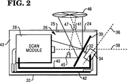
- Fig. 2 is a side diagrammatic view of an optical scanner embodying the present invention and illustrating the arrangement of the scan module and the tilted reflecting mirror;
- Fig. 3 is a more detailed schematic representation of the scanning system of the optical scanner of Fig. 2;
- Fig. 4 is a sectional side view of the scan module of Fig. 3;
- Fig. 5 is a plan view of the scan pattern generated by the scan module of Fig. 4; and
- Fig. 6 is a plan view of the scan pattern generated by a tilted reflecting mirror.
- Referring now to Fig. 1, there is shown a perspective view of a compact
optical scanner 18. Thescanner 18 comprises a box-like housing structure 20 which includes acover portion 22 having located at one end a glass coveredaperture 24. Mounted in one corner of the aperture is aninfrared detector 25 whose function will be described more fully hereinafter. Thehousing structure 20 is 7.62 cm wide, 15.24 cm long and 5.08 cm thick, providing an interior volume of 589.93 cm . These dimensions enable an operator to grasp thehousing structure 20 for use as a handle held scanner. If thehousing structure 20 is positioned on a supporting surface, the scanner may function as a stationary scanner where a merchandise item is moved across thetop surface 22 of thehousing structure 20 to locate a bar code label adjacent theaperture 24. - Referring to Fig. 2, there is shown a side diagrammatic representation of the
scanning system 26 which is mounted within thehousing structure 20. Included in the system is ascan module 28 which generates a first multi-line scan pattern 44( Fig. 5) and a rotating reflectingmirror 30 which is mounted offset to the rotational axis of thedrive shaft 32 of amotor 34 which engages and rotates themirror 30. Thedrive shaft 32 is orientated in a direction perpendicular to areference plane 36 which in turn is orientated at a 45 degree angle to thespin axis 38 of a drive shaft 50 (Figs. 3 and 4) located in thescan module 28. Thespin axis 38 corresponds to a first scan axis about which the scan pattern 44 (Fig. 5) is projected. The construction of the scan module is fully disclosed i U.S. Patent No. 4,971,410. Themotor 34 and thescan module 28 are mounted on asupport member 40 secured to thehousing structure 20. Mounted adjacent thesupport member 40 is a printedcircuit board 42 which supplies power to themotor 34 and thescan module 28 from a battery (not shown) mounted adjacent the printedcircuit board 42. Thescan module 28 will generate the scan pattern 44 (Fig. 5) which comprises a seven sided star shaped scan pattern. This scan pattern when projected on the rotating reflectingmirror 30 will be rotated by the mirror to generate the multi-line scan pattern 46 (Fig. 6). This scan pattern is projected through the aperture 24 (Fig. 1 and 2) about a second scan axis 41 (Fig. 2) for scanning a bar code label positioned adjacent theaperture 24. - Mounted to the
sidewall 43 of thehousing member 26 is aninfrared LED member 45 which is mounted offset to thesidewall 43 to project aninfrared beam 47 through theaperture 24. Upon the positioning of a merchandise item or a bar code label adjacent theaperture 24, theinfrared beam 47 will be reflected off the item or label in a direction which is detected by the detector 25 (Figs. 1 and 2). In response to receiving the reflectedinfrared beam 47, thedetector 25 will generate an electrical signal in a manner that is well known in the art, which signal is used to initiate a scanning operation of thebar code scanner 18. Upon removal of the item or label from adjacent theaperture 24, the reflected beam will be removed from thedetector 25, resulting in thescanner 18 being disabled from operation. - Referring to Fig. 3, there is shown a more detailed schematic representation of the scanning system located within the
housing structure 20. Thescan module 28 includes alaser source 48 such as a laser diode positioned at one end of ahollow drive shaft 50 driven by amotor 52. Mounted on the other end of the drive shaft is anoptical transceiver 54 which, as will be described more fully hereinafter, includes a deflecting portion 88 (Fig. 4) extending obliquely across the spin axis 38 (Fig. 2) of thedrive shaft 50. Upon the operation of thelaser source 48 as a result of thedetector 25 receiving the reflectedinfrared beam 47, a laser beam will be projected through thedrive shaft 50 to be deflected by thedeflecting portion 88 of thetransceiver 54 in a direction generally perpendicular to the spin axis 38 (Fig. 2) of thedrive shaft 50 towards a ring ofpattern forming mirrors 56. Themirrors 56 will deflect the received laser light beams through the opening of the scan module towards the reflectingmirror 30 rotated by themotor 34 which in turn will generate the scan pattern 46 (Fig. 6). Preferably,motors - The
scan pattern 46 is projected through the aperture 24 (Fig. 1) in thehousing structure 20 towards abar code label 58 positioned adjacent theaperture 24. The light reflected from the bar code label is redirected towards the reflectingmirror 30 which in turn deflects the reflected light beams towards thepattern forming mirrors 56 which direct the light beams to a collection portion 90 (Fig. 4) of theoptical transceiver 54. Thecollection portion 90 deflects the received light beam towards aphotodetector 60 located in the front portion of thescan module 28. Thephotodetector 60 will generate signals representing the intensity of the light beams reflected off thebar code label 58, which signals are transmitted overline 62 to the printedcircuit board 42. The printedcircuit board 42 contains processing means (not shown) for controlling the operation of thescanner 18, for decoding the signals generated by thephotodetector 60 and for transmitting the decoded signals over thecoiled cable 62 to aremote processing member 63. When theoptical scanner 18 is mounted on a supporting surface, power is supplied to the printed circuit board and to thelaser diode 48, themotor 52 and thephotodetector 60 by means of a power source such as anelectrical plug 66 via thecable 62 and theremote processing unit 63. The printedcircuit board 42 contains electronics for operating aloud speaker 68 or agreen indicator light 70 indicating a valid read operation. The electronics on the printedcircuit board 42 will also operate ared indicator light 72 indicating a bad read operation. - Referring now to Fig. 4, there is shown a sectional side view of the
scan module 28. The scan module includes a moldedframe support member 74 having a plurality oflatching portions 76. Mounted within thesupport member 74 is themotor 52. Journaled within themotor 52 bybearings 78 is thehollow drive shaft 50 extending through themotor 52. Mounted within arear extension portion 80 of theframe support member 74 is a brass laserdiode support member 82 supporting thelaser diode 48 and a collimating and a focusinglens member 84, both of which are in alignment with thespin axis 38 of thedrive shaft 50. Thediode 48 outputs a diverging light beam which is collimated and focused on a reference plane (not shown) located in front of the scanning unit by thelens member 84. - Slidably mounted within the
frame support member 74 is a moldedmirror support member 86 constructed of any type of polycarbonate plastic which includes a plurality of acrylic turning orpattern mirrors 56, each of which is attached to and extends outwardly from thesupport member 86 at an angle of approximately thirty-three degrees and in which each mirror is offset to each of theother mirrors 56 by approximately three degrees. The number of mirrors employed is controlled by the number of scan lines required for the scan pattern. In thescan module 28, there are seventurning mirrors 56. Secured to the front end of thedrive shaft 50 is theoptical transceiver 54 comprising a flatdeflecting mirror portion 88 which extends obliquely across thespin axis 38 of thedrive shaft 50 and acollection mirror portion 90 comprising a sloping asphericconcave surface 92 for collecting the scanning light beams reflected from a scanned bar code label. - The deflecting
mirror portion 88 extends through aslot 94 in the collectingsurface 92 of thecollection mirror portion 90. The mirror portion is orientated at an oblique angle to thesurface 92. Mounted within a protrudinghousing portion 96 of asupport member 98 is thephotodetector 60 mounted within aholder 100 secured to the inside end portion of thehousing portion 96. - The operation of the
laser diode 48 will output a narrow laser light beam along thespin axis 38 of thescan module 28. The laser light beam will travel through thehollow drive shaft 50 where it impacts on the rotatingdeflecting mirror portion 88 of theoptical transceiver 54. The light beam designated as 102 in Fig. 3 will be deflected outwardly by the deflectingmirror portion 88 to impact on the turning mirrors 56 which in turn deflect the light beam in a forward direction through theacrylic support member 98 forming the star shaped scanning pattern 44 (Fig. 5) As previously described, this scan pattern is projected onto the rotating tiltedmirror member 30 which will rotate thescan pattern 44 about the scan axis 41 (Fig. 2) forming the highly-dense multi-line scan pattern 46 (Fig. 6). - By varying the speed of the
motor 52 in thescan module 28 and themotor 34, the number of scan lines in thescan pattern 46 can be varied. The speed ofmotor 34 is one-twentieth the speed ofmotor 52, which in the preferred embodiment is forty-eight hundred rpm. As mentioned above, by increasing the speed ratio between themotor 52 and themotor 34 by decreasing the speed of themotor 34, the scan pattern generated effectively reads bar code labels having high aspect ratio. - The scan pattern 46 (Fig. 2) is projected through the
glass aperture 24 in thetop surface 22 off thehousing structure 20 for scanning the bar code label 58 (Fig. 3). The laser light beams reflected from thebar code label 58 will be redirected back to the turning mirrors 56 which deflects the light beams to thecollection portion 90 of theoptical transceiver 54 which will focus the light beams at thephotodetector 60. Thephotodetector 60 will generate electrical signals representating the light intensity of the received light beams and transmit the electrical signals over the line 62 (Fig. 3) to the printedcircuit board 42 where the processing means located on the printed circuit board will decode the received electrical signals and transmit the data either over cable 63 (Fig. 3) or store the information in a storage unit (not shown) located on the printed circuit board which is to be retrieved later. - It will be seen that by this construction a very dense multiple line scan pattern is generated by a compact bar code scanner which may be used as a hand-held scanner or as a stationary scanner and will enable the bar code scanner to improve the efficiency of reading bar code labels irrespective of their size or orientation.
Claims (9)
- A bar code scanner (18) comprising first scanning means (28) for projecting a first multi-line scan pattern along a first scan axis (38), characterized by second scanning means (30) arranged to deflect said first multi-line scan pattern along a first scan axis (38), characterized by second scanning means (30) arranged to deflect said first multi-line scan pattern along a second scan axis (41 ) for scanning a coded indicia (58) said second scanning means (30) being arranged to be driven so as to rotate said first multi-line scan pattern about said second scan axis (41) so as to generate a second multi-line scan pattern having a grater number of scan lines than said first scan pattern.
- A scanner according to claim 1, characterized in that said second scanning means comprises a mirror member (30) arranged to be rotatably driven so as to rotate said first multi-line scan pattern.
- A scanner according to claim 2, chararcterized in that said mirror member (30) comprises a plane mirror rotatably mounted on first drive means (32,34) and arranged so as to be offset from the perpendicular to the axis of rotation thereof
- A scanner according to claim 3, characterized in that said first scanning means (28) includes second drive means (52) arranged to be driven at a different speed from said first drive means (32,34).
- A scanner apparatus according to claim 1, 2, 3 or 4, characterized in that said first scanning means (28) comprises a source (48) of scanning light beams projected along said first scan axis (38), second deflecting means (88) rotatably mounted on said first scan axis (38) and a plurality of pattern forming mirror members (56) mounted around said second deflecting means (88) for deflecting the scanning light beams along said first scan axis (38) in the form of a multi-line scan pattern.
- A scanner according to any one of the preceding claims, characterized by optoelectric light source and detector means (42,25) for detecting the presence of a bar code label adjacent said scanner, and means for operating said scanner in response to the detection of said bar code label.
- A scanner according to claim 6, characterized by a housing member (20) including a top surface (22) in which is located an aperture (24) through which said second multiline scan pattern passes, said detector means (25) being mounted in said top surface (22) adjacent said aperture (24).
- A method of generating a multi-line scan pattern, characterized by projecting a first multi-line scan pattern along a first scan axis (38), deflecting said first multi-line scan pattern along a second scan axis (41) in a manner such that said first multi-line scan pattern rotates about said second scan axis (41) so as form a second multi-line scan pattern having a greater number of scan lines than said first pattern.
- A method according to claim 8, characterized in that drive means (34,52) for providing said first multi-line scan pattern and for causing the rotation of said first multiline scan pattern respectively, are driven at different speeds.
Applications Claiming Priority (2)
| Application Number | Priority Date | Filing Date | Title |
|---|---|---|---|
| US75931691A | 1991-09-13 | 1991-09-13 | |
| US759316 | 1991-09-13 |
Publications (3)
| Publication Number | Publication Date |
|---|---|
| EP0532220A2 true EP0532220A2 (en) | 1993-03-17 |
| EP0532220A3 EP0532220A3 (en) | 1994-03-16 |
| EP0532220B1 EP0532220B1 (en) | 1998-03-04 |
Family
ID=25055205
Family Applications (1)
| Application Number | Title | Priority Date | Filing Date |
|---|---|---|---|
| EP19920307967 Expired - Lifetime EP0532220B1 (en) | 1991-09-13 | 1992-09-02 | Bar code scanner and method of operation |
Country Status (3)
| Country | Link |
|---|---|
| EP (1) | EP0532220B1 (en) |
| JP (1) | JPH05210757A (en) |
| DE (1) | DE69224570T2 (en) |
Cited By (3)
| Publication number | Priority date | Publication date | Assignee | Title |
|---|---|---|---|---|
| EP0626605A1 (en) * | 1993-05-28 | 1994-11-30 | Omron Corporation | Vibrating and rotating optical scanning device |
| EP0650133A2 (en) * | 1993-10-25 | 1995-04-26 | Symbol Technologies, Inc. | Integrated scanner on a common substrate |
| EP0778538A2 (en) | 1995-12-08 | 1997-06-11 | Ncr International Inc. | Optical scanner |
Families Citing this family (1)
| Publication number | Priority date | Publication date | Assignee | Title |
|---|---|---|---|---|
| CN109458533B (en) * | 2018-11-02 | 2020-10-13 | 浙江厚达智能科技股份有限公司 | Jet jacking and rotating device of optical fiber disk code scanner |
Citations (5)
| Publication number | Priority date | Publication date | Assignee | Title |
|---|---|---|---|---|
| US3718761A (en) * | 1968-03-27 | 1973-02-27 | Hughes Aircraft Co | Omnidirectional planar optical code reader |
| DE2238816B1 (en) * | 1972-08-07 | 1973-09-13 | Anker-Werke Ag, 4800 Bielefeld | Electro-optical scanning device for data carriers |
| US4795224A (en) * | 1986-10-06 | 1989-01-03 | Katsuchika Goto | Optical scanning pattern generator |
| US4871904A (en) * | 1987-12-28 | 1989-10-03 | Symbol Technologies, Inc. | Multidirectional optical scanner |
| US4971410A (en) * | 1989-07-27 | 1990-11-20 | Ncr Corporation | Scanning and collection system for a compact laser |
-
1992
- 1992-08-28 JP JP25184492A patent/JPH05210757A/en active Pending
- 1992-09-02 DE DE1992624570 patent/DE69224570T2/en not_active Expired - Fee Related
- 1992-09-02 EP EP19920307967 patent/EP0532220B1/en not_active Expired - Lifetime
Patent Citations (5)
| Publication number | Priority date | Publication date | Assignee | Title |
|---|---|---|---|---|
| US3718761A (en) * | 1968-03-27 | 1973-02-27 | Hughes Aircraft Co | Omnidirectional planar optical code reader |
| DE2238816B1 (en) * | 1972-08-07 | 1973-09-13 | Anker-Werke Ag, 4800 Bielefeld | Electro-optical scanning device for data carriers |
| US4795224A (en) * | 1986-10-06 | 1989-01-03 | Katsuchika Goto | Optical scanning pattern generator |
| US4871904A (en) * | 1987-12-28 | 1989-10-03 | Symbol Technologies, Inc. | Multidirectional optical scanner |
| US4971410A (en) * | 1989-07-27 | 1990-11-20 | Ncr Corporation | Scanning and collection system for a compact laser |
Cited By (5)
| Publication number | Priority date | Publication date | Assignee | Title |
|---|---|---|---|---|
| EP0626605A1 (en) * | 1993-05-28 | 1994-11-30 | Omron Corporation | Vibrating and rotating optical scanning device |
| EP0650133A2 (en) * | 1993-10-25 | 1995-04-26 | Symbol Technologies, Inc. | Integrated scanner on a common substrate |
| EP0650133A3 (en) * | 1993-10-25 | 1995-09-13 | Symbol Technologies Inc | Integrated scanner on a common substrate. |
| EP0778538A2 (en) | 1995-12-08 | 1997-06-11 | Ncr International Inc. | Optical scanner |
| EP0778538A3 (en) * | 1995-12-08 | 1999-02-17 | Ncr International Inc. | Optical scanner |
Also Published As
| Publication number | Publication date |
|---|---|
| EP0532220A3 (en) | 1994-03-16 |
| DE69224570T2 (en) | 1998-10-01 |
| EP0532220B1 (en) | 1998-03-04 |
| JPH05210757A (en) | 1993-08-20 |
| DE69224570D1 (en) | 1998-04-09 |
Similar Documents
| Publication | Publication Date | Title |
|---|---|---|
| US4935610A (en) | Hand-held bar code reader | |
| EP0517958B1 (en) | Combined range laser scanner | |
| US4766298A (en) | Low-profile portable UPC optical scanner | |
| US5015833A (en) | Scan board module for laser scanners | |
| EP0449490B1 (en) | Optical scanning apparatus | |
| US5132523A (en) | Dual mode optical scanning system | |
| US5142131A (en) | Hand-held bar code reader | |
| US5214270A (en) | Modular handheld or fixed scanner | |
| EP0490604B1 (en) | Optical scanning apparatus | |
| EP0318574B1 (en) | Optical scanning apparatus | |
| US5140144A (en) | Scan board module for laser scanners | |
| US6631844B1 (en) | Optical scanner, code reader and bar code reader having increased degree of freedom in placement of optical parts | |
| WO1989005013A1 (en) | Optical scanning apparatus | |
| EP0414452B1 (en) | Hand-held bar code reader | |
| US5192857A (en) | Compact optical scanner rotatable between horizontal and vertical positions | |
| EP0532220B1 (en) | Bar code scanner and method of operation | |
| US5043563A (en) | Portable overhead bar code scanner | |
| US5177347A (en) | Axially invariant pattern scanning apparatus | |
| EP0373934A2 (en) | Hand-held bar code reader | |
| EP0490657B1 (en) | Compact optical scanning system | |
| EP0378766B1 (en) | Scan board module for laser scanners | |
| EP0528630A2 (en) | Optical scanner apparatus | |
| CA1328017C (en) | Scan board module for terminal connected scanner | |
| JPH11203393A (en) | Optical information reader |
Legal Events
| Date | Code | Title | Description |
|---|---|---|---|
| PUAI | Public reference made under article 153(3) epc to a published international application that has entered the european phase |
Free format text: ORIGINAL CODE: 0009012 |
|
| AK | Designated contracting states |
Kind code of ref document: A2 Designated state(s): DE FR GB |
|
| RIN1 | Information on inventor provided before grant (corrected) |
Inventor name: WIKE, DONALD A. JR. Inventor name: COLLINS, DONALD A., JR. |
|
| PUAL | Search report despatched |
Free format text: ORIGINAL CODE: 0009013 |
|
| AK | Designated contracting states |
Kind code of ref document: A3 Designated state(s): DE FR GB |
|
| RAP1 | Party data changed (applicant data changed or rights of an application transferred) |
Owner name: AT&T GLOBAL INFORMATION SOLUTIONS INTERNATIONAL IN |
|
| 17P | Request for examination filed |
Effective date: 19940903 |
|
| RAP1 | Party data changed (applicant data changed or rights of an application transferred) |
Owner name: NCR INTERNATIONAL, INC. |
|
| 17Q | First examination report despatched |
Effective date: 19960724 |
|
| GRAG | Despatch of communication of intention to grant |
Free format text: ORIGINAL CODE: EPIDOS AGRA |
|
| GRAG | Despatch of communication of intention to grant |
Free format text: ORIGINAL CODE: EPIDOS AGRA |
|
| GRAH | Despatch of communication of intention to grant a patent |
Free format text: ORIGINAL CODE: EPIDOS IGRA |
|
| GRAH | Despatch of communication of intention to grant a patent |
Free format text: ORIGINAL CODE: EPIDOS IGRA |
|
| GRAA | (expected) grant |
Free format text: ORIGINAL CODE: 0009210 |
|
| AK | Designated contracting states |
Kind code of ref document: B1 Designated state(s): DE FR GB |
|
| REF | Corresponds to: |
Ref document number: 69224570 Country of ref document: DE Date of ref document: 19980409 |
|
| ET | Fr: translation filed | ||
| PLBE | No opposition filed within time limit |
Free format text: ORIGINAL CODE: 0009261 |
|
| STAA | Information on the status of an ep patent application or granted ep patent |
Free format text: STATUS: NO OPPOSITION FILED WITHIN TIME LIMIT |
|
| 26N | No opposition filed | ||
| PGFP | Annual fee paid to national office [announced via postgrant information from national office to epo] |
Ref country code: GB Payment date: 19990705 Year of fee payment: 8 |
|
| PGFP | Annual fee paid to national office [announced via postgrant information from national office to epo] |
Ref country code: FR Payment date: 19990723 Year of fee payment: 8 |
|
| PGFP | Annual fee paid to national office [announced via postgrant information from national office to epo] |
Ref country code: DE Payment date: 19990827 Year of fee payment: 8 |
|
| PG25 | Lapsed in a contracting state [announced via postgrant information from national office to epo] |
Ref country code: GB Free format text: LAPSE BECAUSE OF NON-PAYMENT OF DUE FEES Effective date: 20000902 |
|
| GBPC | Gb: european patent ceased through non-payment of renewal fee |
Effective date: 20000902 |
|
| PG25 | Lapsed in a contracting state [announced via postgrant information from national office to epo] |
Ref country code: FR Free format text: LAPSE BECAUSE OF NON-PAYMENT OF DUE FEES Effective date: 20010531 |
|
| PG25 | Lapsed in a contracting state [announced via postgrant information from national office to epo] |
Ref country code: DE Free format text: LAPSE BECAUSE OF NON-PAYMENT OF DUE FEES Effective date: 20010601 |
|
| REG | Reference to a national code |
Ref country code: FR Ref legal event code: ST |