EP0534657A1 - Adsorbent vessel having a convective heat exchanger and flow developer - Google Patents
Adsorbent vessel having a convective heat exchanger and flow developer Download PDFInfo
- Publication number
- EP0534657A1 EP0534657A1 EP92308344A EP92308344A EP0534657A1 EP 0534657 A1 EP0534657 A1 EP 0534657A1 EP 92308344 A EP92308344 A EP 92308344A EP 92308344 A EP92308344 A EP 92308344A EP 0534657 A1 EP0534657 A1 EP 0534657A1
- Authority
- EP
- European Patent Office
- Prior art keywords
- adsorbent
- adsorbent bed
- flow
- gaseous mixture
- heat exchanger
- Prior art date
- Legal status (The legal status is an assumption and is not a legal conclusion. Google has not performed a legal analysis and makes no representation as to the accuracy of the status listed.)
- Withdrawn
Links
Images

Classifications
-
- B—PERFORMING OPERATIONS; TRANSPORTING
- B01—PHYSICAL OR CHEMICAL PROCESSES OR APPARATUS IN GENERAL
- B01D—SEPARATION
- B01D53/00—Separation of gases or vapours; Recovering vapours of volatile solvents from gases; Chemical or biological purification of waste gases, e.g. engine exhaust gases, smoke, fumes, flue gases, aerosols
- B01D53/02—Separation of gases or vapours; Recovering vapours of volatile solvents from gases; Chemical or biological purification of waste gases, e.g. engine exhaust gases, smoke, fumes, flue gases, aerosols by adsorption, e.g. preparative gas chromatography
- B01D53/04—Separation of gases or vapours; Recovering vapours of volatile solvents from gases; Chemical or biological purification of waste gases, e.g. engine exhaust gases, smoke, fumes, flue gases, aerosols by adsorption, e.g. preparative gas chromatography with stationary adsorbents
- B01D53/0407—Constructional details of adsorbing systems
- B01D53/0438—Cooling or heating systems
-
- B—PERFORMING OPERATIONS; TRANSPORTING
- B01—PHYSICAL OR CHEMICAL PROCESSES OR APPARATUS IN GENERAL
- B01J—CHEMICAL OR PHYSICAL PROCESSES, e.g. CATALYSIS OR COLLOID CHEMISTRY; THEIR RELEVANT APPARATUS
- B01J8/00—Chemical or physical processes in general, conducted in the presence of fluids and solid particles; Apparatus for such processes
- B01J8/02—Chemical or physical processes in general, conducted in the presence of fluids and solid particles; Apparatus for such processes with stationary particles, e.g. in fixed beds
- B01J8/0242—Chemical or physical processes in general, conducted in the presence of fluids and solid particles; Apparatus for such processes with stationary particles, e.g. in fixed beds the fluid flow within the bed being predominantly vertical
- B01J8/025—Chemical or physical processes in general, conducted in the presence of fluids and solid particles; Apparatus for such processes with stationary particles, e.g. in fixed beds the fluid flow within the bed being predominantly vertical in a cylindrical shaped bed
-
- B—PERFORMING OPERATIONS; TRANSPORTING
- B01—PHYSICAL OR CHEMICAL PROCESSES OR APPARATUS IN GENERAL
- B01J—CHEMICAL OR PHYSICAL PROCESSES, e.g. CATALYSIS OR COLLOID CHEMISTRY; THEIR RELEVANT APPARATUS
- B01J8/00—Chemical or physical processes in general, conducted in the presence of fluids and solid particles; Apparatus for such processes
- B01J8/02—Chemical or physical processes in general, conducted in the presence of fluids and solid particles; Apparatus for such processes with stationary particles, e.g. in fixed beds
- B01J8/0278—Feeding reactive fluids
-
- B—PERFORMING OPERATIONS; TRANSPORTING
- B01—PHYSICAL OR CHEMICAL PROCESSES OR APPARATUS IN GENERAL
- B01D—SEPARATION
- B01D2253/00—Adsorbents used in seperation treatment of gases and vapours
- B01D2253/10—Inorganic adsorbents
- B01D2253/106—Silica or silicates
- B01D2253/108—Zeolites
-
- B—PERFORMING OPERATIONS; TRANSPORTING
- B01—PHYSICAL OR CHEMICAL PROCESSES OR APPARATUS IN GENERAL
- B01D—SEPARATION
- B01D2256/00—Main component in the product gas stream after treatment
- B01D2256/12—Oxygen
-
- B—PERFORMING OPERATIONS; TRANSPORTING
- B01—PHYSICAL OR CHEMICAL PROCESSES OR APPARATUS IN GENERAL
- B01D—SEPARATION
- B01D2257/00—Components to be removed
- B01D2257/10—Single element gases other than halogens
- B01D2257/102—Nitrogen
Definitions
- the present invention relates to apparatus for separating a gaseous mixture by pressure swing adsorption.
- Pressure swing adsorption is used to produce a product gas from a multi-component gas mixture by adsorbing a component contained within the gas mixture.
- air is passed under pressure into an adsorbent formed of zeolite pellets to adsorb nitrogen and to produce a product gas composed essentially of oxygen.
- the adsorbent is then regenerated by desorbing nitrogen therefrom.
- Several interconnected adsorbent vessels containing the adsorbent are ordinarily used in carrying out the pressure swing adsorption process so that the adsorbent vessels can alternately be used to produce product or to regenerate the adsorbent.
- Adsorption by the adsorbent is exothermic while desorption of the adsorbent is endothermic. If a pressure swing adsorption process were conducted to thermodynamic perfection, then the heat produced by adsorption could be used in desorption. However, adsorption does not occur uniformly in the adsorbent bed. Additionally, heat is carried away in the product gas and the desorbed gas. As a result, a cold spot forms near an inlet of the adsorption vessel and a hot spot forms near an outlet of the adsorption vessel.
- the adsorption capacity of some adsorbents such as zeolites decreases with decreasing temperature, and therefore, the effectiveness of the adsorption decreases within the cold spot.
- Another possible factor that can decrease the effectiveness of adsorption concerns the flow of the gas mixture into the adsorbent bed. For instance, if a bend or tee fitting is located too close to the inlet of the adsorbent vessel, the flow of the gas mixture will not be fully developed upon its entry into the adsorbent vessel. That is, the flow velocity will vary across the flow of the gas mixture. The disadvantage of this is that the gas mixture will be distributed on an unequal basis within the adsorbent bed and thereby decrease the degree to which the component of the gas mixture is actually adsorbed in the adsorbent bed.
- One aim of the present invention is to provide an apparatus that has principal use in increasing the temperature of the cold spot, and therefore, decreasing the deterioration of the adsorbent capacity of the adsorbent due to the cold spot.
- a further aim of the present invention is to provide a compact device to fully develop flow entering an adsorbent bed to insure that the gas to be separated is equally distributed throughout the adsorbent bed.
- an apparatus for separating a gaseous mixture by pressure swing adsorption comprises a vessel containing a bed of adsorbent material which preferentially adsorbs one or more constituents of the gaseous mixture relative to a selected constituent, the vessel having an inlet for the gaseous mixture and an outlet for the selected constituent, and an elongate member located within the vessel and extending at least partially into the adsorbent bed characterised in that the member includes at least two oppositely directed lengthwise extending passes one of which is in fluid communication with the inlet whilst the other of which is in fluid communication with the adsorbent bed, the arrangement being such that the gaseous mixture when passing from the inlet towards the adsorbent bed and adsorbed constituent(s) when desorbed from the adsorbent bed and passing towards the inlet each flow through the passes successively.
- the pass through which the incoming gaseous mixture flows immediately prior to flowing through the adsorbent bed is dimensioned to provide a straight run having a length sufficient to develop fully the flow of the gaseous mixture.
- the member may be made of heat conduction material such that the flow of gases through the passes transfers heat to the adsorbent bed.
- an adsorbent vessel 10 has an interior 12 for containing a zeolite adsorbent for use in fractionating oxygen from air.
- adsorbent vessel 10 could be shaped wider and flatter than the form illustrated in complete dependence upon process considerations and the amount of adsorbent to be utilized.
- a pair of opposed inlet and outlet distributors 14 and 16 are provided at openings 18 and 20 at the ends of adsorbent vessel 10 and are held in place in a manner well known in the art.
- Both inlet and outlet flow distributors 14 and 16 are provided with end walls 22 and 24 and sidewalls 26 and 28 of cylindrical configuration projecting into openings 18 and 20.
- End walls 22 and 24 are provided with inlet and outlet openings 30 and 32 defined in end walls 22 and 24 and sidewalls 26 and 28 are provided with a plurality of slit-like apertures 34 and 36.
- Outlet distributor 16 is provided with an opposed end wall 37 connected to sidewall 28 thereof so that process gases are constrained to pass through slit-like apertures 36 of of sidewall 28.
- Inlet distributor 14 is not provided with such an opposed end wall and as such constitutes a modified form of a flow distributor for purposes that will become apparent.
- Inlet and outlet pipes 38 and 40 pass through inlet and outlet openings 30 and 32 of end walls 22 and 24 and are welded to end walls 22 and 24.
- Pressurized air enters interior 12 of adsorbent vessel 10 via the inlet pipe 38 for adsorption of nitrogen within the zeolite adsorbent that can be contained within adsorbent vessel 10.
- the zeolite adsorbent not illustrated, is contained and supported within adsorbent vessel 10 between perforate supporting structures 42 and 44, well known in the art, that allow passage of the process gases to and from the adsorbent.
- the perforate supporting structures allow a sufficient volume to be created within interior 12 of adsorbent vessel 10 above and below the zeolite adsorbent to allow for the accumulation and distribution of process gases.
- a cold spot tends to form within the zeolite contained within adsorbent vessel 10 closer to inlet distributor 14 than to outlet distributor 16.
- the cold spot exists within the central, lower one third region of the zeolite contained within the vessel.
- the reduction in temperature of the zeolite within the cold spot decreases the capacity of zeolite to adsorb nitrogen.
- the cold spot is heated by an elongated, convective heat exchanger 46 fabricated from a heat conductive material, for instance stainless steel. Heat exchanger 46 is located within the adsorbent vessel so as to extend into the cold spot.
- Heat exchanger 46 has a reversing flow path for either the air entering interior 12 of adsorbent vessel 10 or desorbed nitrogen passing out of interior 12 of adsorbent vessel 10. Since the air is much warmer than the cold spot, typically 0° C., but as low as -60° C., the reversing path taken by the entering air tends to raise the temperature of the cold spot. Additionally, since desorbed nitrogen is approximately 20° C., a good deal warmer than the cold spot, heat tends to transfer to the cold spot from also the outgoing desorbed nitrogen to raise the temperature of the cold spot, and thus, prevent deterioration of the performance of the zeolite adsorbent.
- Convective heat exchanger 46 comprises inlet pipe 38, which is sized to project inwardly and is left open to form an inner tube of heat exchanger 46, an outer tube 48, and an inner end cap 50.
- Inner end cap 50 is connected to one of the ends of outer tube 48.
- Outer tube 48 is connected at the other of its ends to cylindrical sidewall 26 of inlet distributor 16.
- the resulting structure of heat exchanger 46 has two oppositely directed, lengthwise extending passes formed by inlet pipe 38 and an annular flow area 52 formed between inlet pipe 38 and outer tube 48. For instance, air passing through the pass formed by inlet pipe 38 flows toward and into the cold spot to heat the cold spot. The air then reverses direction at inner end cap 50 and then flows through the pass formed by annular flow area 52.
- the air then flows into inlet distributer 18 and passes into interior 12 of vessel 10 through slit-like apertures 34 thereof. After passage through slit-like apertures 34, the air reverses direction again in its flow to the adsorbent. The desorbed nitrogen flows along a flow path that is the reverse of that taken by the entering air.
- the passes are designed to allow heat to be transferred, through the heat conductive material forming elongated heat exchanger 46, to the cold spot from the air or desorbed nitrogen during their transverse of the reversing flow path defined by the two passes. Practically, this is accomplished by appropriately sizing heat exchanger 46 to extend into the cold spot region or slightly past the cold spot region of the adsorbent bed. If necessary, heat exchanger 46 can extend the full length of adsorption vessel 10.
- Heat exchanger 46 can serve to develop fully the air flow into adsorbent vessel 10 in the event that such flow is not fully developed. In this regard, it is sometimes necessary to locate tee fittings and bends, through which air flows to the adsorbent vessel, very near the inlet to the adsorbent vessel. As the air flow changes direction around a bend or through a tee fitting, the velocity distribution across the air flow becomes non-uniform or not fully developed. Normally a straight run of six or more pipe diameters are provided after the tee fitting or bend to allow the air flow to fully develop before entering the adsorbent vessel.
- the non-uniform velocity distribution across the air flow will cause the air to non-uniformly distribute itself in the adsorbent vessel and thus, the adsorbent.
- adsorbent will be unequally utilized to decrease the adsorption capability of the adsorption bed.
- Convective heat exchanger 46 solves this problem by providing a sufficient straight run of flow for the entering air to fully develop prior to its entry into the adsorbent bed.
- this sufficient straight run is provided by annular flow area 52.
- flow straighteners such as radially extending plates 54 can be provided within annular flow area 52. In place of plates 54, bundles of open ended pipes could be inserted into annular flow area 52.
- heat exchanger 46 can be designed also to develop fully the flow of incoming air.
- heat exchanger 46 can be solely designed to solve flow development problems without regard to potential cold spot problems.
- the flow areas of annular flow area 52 and inlet pipe 38 should each be no less than the transverse cross-sectional are of process piping to prevent excessive pressure drops in the process piping.
- other possible embodiments of the subject invention could include the use of more than one elongated, convective heat exchanger or an elongated convective heat exchanger having more than two passes. The disadvantage of such embodiments would be the increase in pressure drop produced by the additional passes.
Abstract
The present invention provides an adsorbent vessel adapted to contain an adsorbent and form an adsorbent bed for use in adsorbing a component of a multicomponent gas mixture during a pressure swing adsorption process. In accordance with such process the adsorbent bed is regenerated by desorbing the adsorbed component. The adsorption capacity of the adsorbent decreases with decreasing temperature and the pressure swing adsorption process produces a cold spot of reduced temperature within a region of the adsorbent bed. In order to combat the resulting decreased adsorption capacity, a convective heat exchanger extends into the cold spot to raise the temperature of the cold spot. The convective heat exchanger is provided with at least two passes for the entering multi-component gas mixture or the outward bound desorbed component to transverse and thereby transfer heat to the cold spot. Additionally, the heat exchanger can also serve to supply a sufficiently long straight run for the entering multi-component gas mixture to fully develop. The full development of the entering flow prevents unequal distribution of the multi-component gas mixture within the adsorbent bed.
Description
- The present invention relates to apparatus for separating a gaseous mixture by pressure swing adsorption.
- Pressure swing adsorption is used to produce a product gas from a multi-component gas mixture by adsorbing a component contained within the gas mixture. In a typical pressure swing adsorption process to generate oxygen, air is passed under pressure into an adsorbent formed of zeolite pellets to adsorb nitrogen and to produce a product gas composed essentially of oxygen. The adsorbent is then regenerated by desorbing nitrogen therefrom. Several interconnected adsorbent vessels containing the adsorbent are ordinarily used in carrying out the pressure swing adsorption process so that the adsorbent vessels can alternately be used to produce product or to regenerate the adsorbent.
- Adsorption by the adsorbent is exothermic while desorption of the adsorbent is endothermic. If a pressure swing adsorption process were conducted to thermodynamic perfection, then the heat produced by adsorption could be used in desorption. However, adsorption does not occur uniformly in the adsorbent bed. Additionally, heat is carried away in the product gas and the desorbed gas. As a result, a cold spot forms near an inlet of the adsorption vessel and a hot spot forms near an outlet of the adsorption vessel. The adsorption capacity of some adsorbents such as zeolites, however, decreases with decreasing temperature, and therefore, the effectiveness of the adsorption decreases within the cold spot.
- Another possible factor that can decrease the effectiveness of adsorption concerns the flow of the gas mixture into the adsorbent bed. For instance, if a bend or tee fitting is located too close to the inlet of the adsorbent vessel, the flow of the gas mixture will not be fully developed upon its entry into the adsorbent vessel. That is, the flow velocity will vary across the flow of the gas mixture. The disadvantage of this is that the gas mixture will be distributed on an unequal basis within the adsorbent bed and thereby decrease the degree to which the component of the gas mixture is actually adsorbed in the adsorbent bed.
- One aim of the present invention is to provide an apparatus that has principal use in increasing the temperature of the cold spot, and therefore, decreasing the deterioration of the adsorbent capacity of the adsorbent due to the cold spot. A further aim of the present invention is to provide a compact device to fully develop flow entering an adsorbent bed to insure that the gas to be separated is equally distributed throughout the adsorbent bed.
- According to the present invention an apparatus for separating a gaseous mixture by pressure swing adsorption comprises a vessel containing a bed of adsorbent material which preferentially adsorbs one or more constituents of the gaseous mixture relative to a selected constituent, the vessel having an inlet for the gaseous mixture and an outlet for the selected constituent, and an elongate member located within the vessel and extending at least partially into the adsorbent bed characterised in that the member includes at least two oppositely directed lengthwise extending passes one of which is in fluid communication with the inlet whilst the other of which is in fluid communication with the adsorbent bed, the arrangement being such that the gaseous mixture when passing from the inlet towards the adsorbent bed and adsorbed constituent(s) when desorbed from the adsorbent bed and passing towards the inlet each flow through the passes successively.
- In a preferred embodiment, the pass through which the incoming gaseous mixture flows immediately prior to flowing through the adsorbent bed is dimensioned to provide a straight run having a length sufficient to develop fully the flow of the gaseous mixture.
- The member may be made of heat conduction material such that the flow of gases through the passes transfers heat to the adsorbent bed.
- An embodiment of the invention will now be described by way of examples, reference being made to the Figures of the accompanying diagrammatic drawings in which:-
- Fig. 1 is a schematic, sectional view of an adsorbent vessel in accordance with the present invention; and
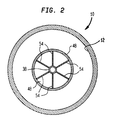
- Fig. 2 is a sectional view taken along line 2-2 of Fig. 1.
- As shown, an
adsorbent vessel 10 has aninterior 12 for containing a zeolite adsorbent for use in fractionating oxygen from air. As would be appreciated by those skilled in the art,adsorbent vessel 10 could be shaped wider and flatter than the form illustrated in complete dependence upon process considerations and the amount of adsorbent to be utilized. - A pair of opposed inlet and
outlet distributors openings adsorbent vessel 10 and are held in place in a manner well known in the art. Both inlet andoutlet flow distributors end walls sidewalls openings End walls outlet openings end walls sidewalls like apertures Outlet distributor 16 is provided with anopposed end wall 37 connected tosidewall 28 thereof so that process gases are constrained to pass through slit-like apertures 36 of ofsidewall 28.Inlet distributor 14 is not provided with such an opposed end wall and as such constitutes a modified form of a flow distributor for purposes that will become apparent. - Inlet and
outlet pipes outlet openings end walls end walls interior 12 ofadsorbent vessel 10 via theinlet pipe 38 for adsorption of nitrogen within the zeolite adsorbent that can be contained withinadsorbent vessel 10. The zeolite adsorbent, not illustrated, is contained and supported withinadsorbent vessel 10 between perforate supportingstructures interior 12 ofadsorbent vessel 10 above and below the zeolite adsorbent to allow for the accumulation and distribution of process gases. - The adsorption of nitrogen within the zeolite adsorbent produces a product oxygen gas essentially free of the nitrogen which is discharged from
adsorbent vessel 10 viaoutlet conduit 40. As would be known to those skilled in the art, additional process streams such as purge, backfill and equalization gases also flow to and fromvessel 10 throughoutlet conduit 40. During regeneration, reduced pressure is applied toinlet conduit 38 to cause adsorbed nitrogen to desorb from the zeolite and be drawn fromadsorbent vessel 10 throughinlet conduit 38. - As mentioned previously, due to heat of adsorption, a cold spot tends to form within the zeolite contained within
adsorbent vessel 10 closer toinlet distributor 14 than tooutlet distributor 16. Inadsorbent vessel 10, the cold spot exists within the central, lower one third region of the zeolite contained within the vessel. The reduction in temperature of the zeolite within the cold spot decreases the capacity of zeolite to adsorb nitrogen. In the present invention, the cold spot is heated by an elongated,convective heat exchanger 46 fabricated from a heat conductive material, for instance stainless steel.Heat exchanger 46 is located within the adsorbent vessel so as to extend into the cold spot. -
Heat exchanger 46 has a reversing flow path for either the air entering interior 12 ofadsorbent vessel 10 or desorbed nitrogen passing out ofinterior 12 ofadsorbent vessel 10. Since the air is much warmer than the cold spot, typically 0° C., but as low as -60° C., the reversing path taken by the entering air tends to raise the temperature of the cold spot. Additionally, since desorbed nitrogen is approximately 20° C., a good deal warmer than the cold spot, heat tends to transfer to the cold spot from also the outgoing desorbed nitrogen to raise the temperature of the cold spot, and thus, prevent deterioration of the performance of the zeolite adsorbent. -
Convective heat exchanger 46 comprisesinlet pipe 38, which is sized to project inwardly and is left open to form an inner tube ofheat exchanger 46, anouter tube 48, and aninner end cap 50.Inner end cap 50 is connected to one of the ends ofouter tube 48.Outer tube 48 is connected at the other of its ends tocylindrical sidewall 26 ofinlet distributor 16. The resulting structure ofheat exchanger 46 has two oppositely directed, lengthwise extending passes formed byinlet pipe 38 and anannular flow area 52 formed betweeninlet pipe 38 andouter tube 48. For instance, air passing through the pass formed byinlet pipe 38 flows toward and into the cold spot to heat the cold spot. The air then reverses direction atinner end cap 50 and then flows through the pass formed byannular flow area 52. The air then flows intoinlet distributer 18 and passes into interior 12 ofvessel 10 through slit-like apertures 34 thereof. After passage through slit-like apertures 34, the air reverses direction again in its flow to the adsorbent. The desorbed nitrogen flows along a flow path that is the reverse of that taken by the entering air. - The passes are designed to allow heat to be transferred, through the heat conductive material forming
elongated heat exchanger 46, to the cold spot from the air or desorbed nitrogen during their transverse of the reversing flow path defined by the two passes. Practically, this is accomplished by appropriately sizingheat exchanger 46 to extend into the cold spot region or slightly past the cold spot region of the adsorbent bed. If necessary,heat exchanger 46 can extend the full length ofadsorption vessel 10. -
Heat exchanger 46 can serve to develop fully the air flow intoadsorbent vessel 10 in the event that such flow is not fully developed. In this regard, it is sometimes necessary to locate tee fittings and bends, through which air flows to the adsorbent vessel, very near the inlet to the adsorbent vessel. As the air flow changes direction around a bend or through a tee fitting, the velocity distribution across the air flow becomes non-uniform or not fully developed. Normally a straight run of six or more pipe diameters are provided after the tee fitting or bend to allow the air flow to fully develop before entering the adsorbent vessel. When this is not or cannot be done because of other design considerations, the non-uniform velocity distribution across the air flow will cause the air to non-uniformly distribute itself in the adsorbent vessel and thus, the adsorbent. As a result, adsorbent will be unequally utilized to decrease the adsorption capability of the adsorption bed. -
Convective heat exchanger 46 solves this problem by providing a sufficient straight run of flow for the entering air to fully develop prior to its entry into the adsorbent bed. In this regard, this sufficient straight run is provided byannular flow area 52. In order to decrease the length ofannular flow area 52 and hence,heat exchanger 46, required for such a purpose, flow straighteners such as radially extendingplates 54 can be provided withinannular flow area 52. In place ofplates 54, bundles of open ended pipes could be inserted intoannular flow area 52. - In the event that in addition to a cold spot problem, a flow development problem, as described above, is inherent in the pressure swing adsorption system design, then heat exchanger can be designed also to develop fully the flow of incoming air. As may be appreciated,
heat exchanger 46 can be solely designed to solve flow development problems without regard to potential cold spot problems. In any possible embodiment of or use ofheat exchanger 46, the flow areas ofannular flow area 52 andinlet pipe 38 should each be no less than the transverse cross-sectional are of process piping to prevent excessive pressure drops in the process piping. In addition to the foregoing, other possible embodiments of the subject invention could include the use of more than one elongated, convective heat exchanger or an elongated convective heat exchanger having more than two passes. The disadvantage of such embodiments would be the increase in pressure drop produced by the additional passes.
Claims (6)
- Apparatus for separating a gaseous mixture by pressure swing adsorption comprising a vessel (10) containing a bed of adsorbent material which preferentially adsorbs one or more constituents of the gaseous mixture relative to a selected constituent, the vessel (10) having an inlet (14) for the gaseous mixture and an outlet (16) for the selected constituent, and an elongate member (46) located within the vessel (10) and extending at least partially into the adsorbent bed characterised in that the member (46) includes at least two oppositely directed lengthwise extending passes (38, 52) one (38) of which is in fluid communication with the inlet (14) whilst the other (52) of which is in fluid communication with the adsorbent bed, the arrangement being such that the gaseous mixture when passing from the inlet (14) towards the adsorbent bed and adsorbed constituent(s) when desorbed from the adsorbent bed and passing towards the inlet 14 each flow through the passes (38, 52) successively.
- Apparatus as claimed in Claim 1, characterised in that the pass (52) through which the incoming gaseous mixture flows immediately prior to flowing through the adsorbent bed is dimensioned to provide a straight run having a length sufficient to develop fully the flow of the gaseous mixture.
- Apparatus as claimed Claim 1 or 2, characterised in that the member (46) is made of heat conduction material such that the flow of gases through the passes (38.52) transfers heat to the adsorbent bed.
- Apparatus as claimed in Claim 1,2 or 3, characterised in that said one pass comprises a hollow elongate inner tube (38) which extends coaxially within but spaced from an elongate outer tube (48), the tubes (38, 48) defining between them an annular flow area (52) comprising said other pass, and an end cap (50) connected to one end of the tube (48).
- Apparatus as claimed in Claim 4, characterised in that means is provided for straightening the flow of the gaseous mixture through the annular flow area (52).
- Apparatus as claimed in Claim 5, characterised in that the flow straightening means is at least one plate (54) extending radially from the outer surface of the inner tube (38) to the inner surface of the outer tube (48).
Applications Claiming Priority (2)
| Application Number | Priority Date | Filing Date | Title |
|---|---|---|---|
| US07/765,609 US5160355A (en) | 1991-09-25 | 1991-09-25 | Adsorbent vessel having a convective heat exchanger and flow developer |
| US765609 | 1991-09-25 |
Publications (1)
| Publication Number | Publication Date |
|---|---|
| EP0534657A1 true EP0534657A1 (en) | 1993-03-31 |
Family
ID=25073999
Family Applications (1)
| Application Number | Title | Priority Date | Filing Date |
|---|---|---|---|
| EP92308344A Withdrawn EP0534657A1 (en) | 1991-09-25 | 1992-09-14 | Adsorbent vessel having a convective heat exchanger and flow developer |
Country Status (9)
| Country | Link |
|---|---|
| US (1) | US5160355A (en) |
| EP (1) | EP0534657A1 (en) |
| JP (1) | JPH0639231A (en) |
| AU (1) | AU641866B2 (en) |
| CA (1) | CA2072295A1 (en) |
| NZ (1) | NZ243122A (en) |
| TR (1) | TR26447A (en) |
| TW (1) | TW221980B (en) |
| ZA (1) | ZA925021B (en) |
Cited By (3)
| Publication number | Priority date | Publication date | Assignee | Title |
|---|---|---|---|---|
| EP0636399A2 (en) * | 1993-07-29 | 1995-02-01 | The BOC Group plc | A vessel baffle arrangement |
| CN106043961A (en) * | 2016-08-15 | 2016-10-26 | 安徽翼迈科技股份有限公司 | Two-component epoxy adhesive storage device |
| RU2805091C2 (en) * | 2019-05-08 | 2023-10-11 | Линде Гмбх | Pressure vessel |
Families Citing this family (8)
| Publication number | Priority date | Publication date | Assignee | Title |
|---|---|---|---|---|
| DE4119660C2 (en) * | 1991-06-14 | 1994-03-31 | Draegerwerk Ag | Air cleaning cartridge for a respirator with an insert |
| DE4243816A1 (en) * | 1992-12-23 | 1994-06-30 | Zeolith Tech | Sorbent cartridge |
| US5453112A (en) * | 1994-02-02 | 1995-09-26 | Praxair Technology, Inc. | Pressure swing adsorption heat recovery |
| US7881390B2 (en) | 2004-12-01 | 2011-02-01 | Intel Corporation | Increased discrete point processing in an OFDM communication system |
| US7491259B2 (en) * | 2006-05-09 | 2009-02-17 | Equistar Chemicals, Lp | Residence time distribution method and apparatus for operating a curvilinear pressure vessel where transport phenomena take place |
| US7531024B2 (en) * | 2006-05-17 | 2009-05-12 | Equistar Chemicals, Lp | Plug-flow method and apparatus for operating a curvilinear pressure vessel where transport phenomena occur |
| US8500884B2 (en) | 2010-09-27 | 2013-08-06 | Uop Llc | Vessel and process pertaining to an impermeable impingement plate |
| PL2630420T3 (en) * | 2010-10-20 | 2015-06-30 | Coldway | Thermochemical system having a modular connection |
Citations (4)
| Publication number | Priority date | Publication date | Assignee | Title |
|---|---|---|---|---|
| US3258899A (en) * | 1962-02-06 | 1966-07-05 | Puregas Equipment Corp | Apparatus for fractionating gaseous mixtures |
| DE2655936A1 (en) * | 1975-12-19 | 1977-06-23 | Gen Electric | GAS SEPARATION SYSTEM |
| EP0172003A1 (en) * | 1984-08-13 | 1986-02-19 | Pall Corporation | Sorbing apparatus |
| EP0254936A2 (en) * | 1986-07-15 | 1988-02-03 | The M. W. Kellogg Company | Ammonia synthesis converter |
Family Cites Families (13)
| Publication number | Priority date | Publication date | Assignee | Title |
|---|---|---|---|---|
| US3734293A (en) * | 1970-03-04 | 1973-05-22 | Air Prod & Chem | Thermoelectric adsorber |
| US3800507A (en) * | 1970-06-23 | 1974-04-02 | Us Navy | Low pressure air dehydrator |
| US3735563A (en) * | 1971-11-04 | 1973-05-29 | C Adams | Regenerating desiccator |
| US3917458A (en) * | 1972-07-21 | 1975-11-04 | Nicoll Jr Frank S | Gas filtration system employing a filtration screen of particulate solids |
| NL7610120A (en) * | 1976-09-12 | 1978-03-14 | Droogtech | Pressure vessel for drying compressed air by heat exchange - has only one end cover, facilitating production, inspection and assembly |
| DE7727993U1 (en) * | 1977-09-09 | 1978-02-16 | Bauer - Kompressoren Heinz Bauer, 8000 Muenchen | FILTER CARTRIDGE |
| US4162146A (en) * | 1977-12-14 | 1979-07-24 | Pall Corporation | Multi-chamber adsorbent gas fractionator with non-jamming effluent flow control valve |
| US4312640A (en) * | 1979-03-12 | 1982-01-26 | Pall Corporation | Heat-reactivatable adsorbent gas fractionator and process |
| US4322223A (en) * | 1979-03-30 | 1982-03-30 | Pall Corporation | Adsorbent fractionators with electronic sequence timer cycle control and process |
| US4312641A (en) * | 1979-05-25 | 1982-01-26 | Pall Corporation | Heat-reactivatable adsorbent gas fractionator and process |
| US4552570A (en) * | 1980-05-02 | 1985-11-12 | Pall Corporation | Adsorbent fractionator with automatic cycle control and process |
| FR2541588B1 (en) * | 1983-02-28 | 1985-07-05 | Air Liquide | CONTAINER AND PURIFICATION PLANT BY ADSORPTION |
| JPH01299622A (en) * | 1988-05-30 | 1989-12-04 | Mitsubishi Electric Corp | Air drying apparatus |
-
1991
- 1991-09-25 US US07/765,609 patent/US5160355A/en not_active Expired - Fee Related
-
1992
- 1992-06-12 NZ NZ243122A patent/NZ243122A/en unknown
- 1992-06-15 AU AU18268/92A patent/AU641866B2/en not_active Ceased
- 1992-06-25 CA CA002072295A patent/CA2072295A1/en not_active Abandoned
- 1992-07-06 ZA ZA925021A patent/ZA925021B/en unknown
- 1992-07-22 TW TW081105793A patent/TW221980B/zh active
- 1992-09-02 TR TR92/0833A patent/TR26447A/en unknown
- 1992-09-10 JP JP4242122A patent/JPH0639231A/en active Pending
- 1992-09-14 EP EP92308344A patent/EP0534657A1/en not_active Withdrawn
Patent Citations (4)
| Publication number | Priority date | Publication date | Assignee | Title |
|---|---|---|---|---|
| US3258899A (en) * | 1962-02-06 | 1966-07-05 | Puregas Equipment Corp | Apparatus for fractionating gaseous mixtures |
| DE2655936A1 (en) * | 1975-12-19 | 1977-06-23 | Gen Electric | GAS SEPARATION SYSTEM |
| EP0172003A1 (en) * | 1984-08-13 | 1986-02-19 | Pall Corporation | Sorbing apparatus |
| EP0254936A2 (en) * | 1986-07-15 | 1988-02-03 | The M. W. Kellogg Company | Ammonia synthesis converter |
Cited By (4)
| Publication number | Priority date | Publication date | Assignee | Title |
|---|---|---|---|---|
| EP0636399A2 (en) * | 1993-07-29 | 1995-02-01 | The BOC Group plc | A vessel baffle arrangement |
| EP0636399A3 (en) * | 1993-07-29 | 1995-02-15 | Boc Group Plc | |
| CN106043961A (en) * | 2016-08-15 | 2016-10-26 | 安徽翼迈科技股份有限公司 | Two-component epoxy adhesive storage device |
| RU2805091C2 (en) * | 2019-05-08 | 2023-10-11 | Линде Гмбх | Pressure vessel |
Also Published As
| Publication number | Publication date |
|---|---|
| NZ243122A (en) | 1994-11-25 |
| AU641866B2 (en) | 1993-09-30 |
| CA2072295A1 (en) | 1993-03-26 |
| JPH0639231A (en) | 1994-02-15 |
| AU1826892A (en) | 1993-04-01 |
| TW221980B (en) | 1994-04-01 |
| US5160355A (en) | 1992-11-03 |
| TR26447A (en) | 1995-03-15 |
| ZA925021B (en) | 1993-03-16 |
Similar Documents
| Publication | Publication Date | Title |
|---|---|---|
| US8313561B2 (en) | Radial bed vessels having uniform flow distribution | |
| US11260339B2 (en) | Apparatus and system for swing adsorption processes related thereto | |
| KR100275224B1 (en) | Radial flow adsorption vessel and method for imparting a u-shaped flow pattern to fluids flowing inside the vessel | |
| EP0534657A1 (en) | Adsorbent vessel having a convective heat exchanger and flow developer | |
| US3103425A (en) | Adsorption apparatus and method | |
| US4030896A (en) | Regeneration of adsorbents | |
| US3323292A (en) | Apparatus for fractionating gaseous mixtures | |
| KR100264097B1 (en) | Low pressure gas source and dispensing apparatus with enhanced diffusive/extractive means | |
| US5593475A (en) | Mixed bed adsorber | |
| US5916531A (en) | Spiral fixed-bed module for adsorber and catalytic reactor | |
| JPS6012084B2 (en) | gas fractionator | |
| JP2007529297A (en) | Method and apparatus for removing water and carbon dioxide from a gas mixture using pressure swing adsorption | |
| CN103702753B (en) | Reactor for carrying out autothermal gas-phase dehydrogenation | |
| US3432995A (en) | Adsorption tower | |
| US2678108A (en) | Apparatus for flowing gas through a permeable adsorbent bed | |
| US4371384A (en) | Bed vessels for a compact oxygen concentrator | |
| US4353716A (en) | Process and apparatus for the regeneration of an adsorber | |
| NZ248546A (en) | Adsorbent vessel having two pass flow developer at inlet | |
| RU2257944C1 (en) | Adsorber | |
| EP0045210B1 (en) | An improved cyclic adsorption process | |
| JPH1089805A (en) | Adsorption core for adsorption refrigerator | |
| US6375723B1 (en) | Apparatus for improving gas distribution in a prepurifier | |
| JP2969356B2 (en) | Adsorption tower | |
| SU1150009A1 (en) | Installation for dehumidification and cleaning of gas | |
| RU2040311C1 (en) | Apparatus for gasses purification and / or drying |
Legal Events
| Date | Code | Title | Description |
|---|---|---|---|
| PUAI | Public reference made under article 153(3) epc to a published international application that has entered the european phase |
Free format text: ORIGINAL CODE: 0009012 |
|
| AK | Designated contracting states |
Kind code of ref document: A1 Designated state(s): BE DE ES FR GB IE IT NL SE |
|
| 17P | Request for examination filed |
Effective date: 19930809 |
|
| 17Q | First examination report despatched |
Effective date: 19941109 |
|
| STAA | Information on the status of an ep patent application or granted ep patent |
Free format text: STATUS: THE APPLICATION IS DEEMED TO BE WITHDRAWN |
|
| 18D | Application deemed to be withdrawn |
Effective date: 19951205 |