EP0535912A2 - Hinge mechanism for foldable electronic apparatus - Google Patents
Hinge mechanism for foldable electronic apparatus Download PDFInfo
- Publication number
- EP0535912A2 EP0535912A2 EP92308869A EP92308869A EP0535912A2 EP 0535912 A2 EP0535912 A2 EP 0535912A2 EP 92308869 A EP92308869 A EP 92308869A EP 92308869 A EP92308869 A EP 92308869A EP 0535912 A2 EP0535912 A2 EP 0535912A2
- Authority
- EP
- European Patent Office
- Prior art keywords
- hinge
- casings
- engaging means
- hinge mechanism
- casing
- Prior art date
- Legal status (The legal status is an assumption and is not a legal conclusion. Google has not performed a legal analysis and makes no representation as to the accuracy of the status listed.)
- Granted
Links
Images


Classifications
-
- E—FIXED CONSTRUCTIONS
- E05—LOCKS; KEYS; WINDOW OR DOOR FITTINGS; SAFES
- E05D—HINGES OR SUSPENSION DEVICES FOR DOORS, WINDOWS OR WINGS
- E05D7/00—Hinges or pivots of special construction
-
- H—ELECTRICITY
- H04—ELECTRIC COMMUNICATION TECHNIQUE
- H04M—TELEPHONIC COMMUNICATION
- H04M1/00—Substation equipment, e.g. for use by subscribers
- H04M1/02—Constructional features of telephone sets
- H04M1/0202—Portable telephone sets, e.g. cordless phones, mobile phones or bar type handsets
- H04M1/0206—Portable telephones comprising a plurality of mechanically joined movable body parts, e.g. hinged housings
- H04M1/0208—Portable telephones comprising a plurality of mechanically joined movable body parts, e.g. hinged housings characterized by the relative motions of the body parts
- H04M1/0214—Foldable telephones, i.e. with body parts pivoting to an open position around an axis parallel to the plane they define in closed position
- H04M1/0216—Foldable in one direction, i.e. using a one degree of freedom hinge
-
- E—FIXED CONSTRUCTIONS
- E05—LOCKS; KEYS; WINDOW OR DOOR FITTINGS; SAFES
- E05D—HINGES OR SUSPENSION DEVICES FOR DOORS, WINDOWS OR WINGS
- E05D11/00—Additional features or accessories of hinges
- E05D11/10—Devices for preventing movement between relatively-movable hinge parts
- E05D11/1028—Devices for preventing movement between relatively-movable hinge parts for maintaining the hinge in two or more positions, e.g. intermediate or fully open
- E05D11/1078—Devices for preventing movement between relatively-movable hinge parts for maintaining the hinge in two or more positions, e.g. intermediate or fully open the maintaining means acting parallel to the pivot
-
- E—FIXED CONSTRUCTIONS
- E05—LOCKS; KEYS; WINDOW OR DOOR FITTINGS; SAFES
- E05Y—INDEXING SCHEME RELATING TO HINGES OR OTHER SUSPENSION DEVICES FOR DOORS, WINDOWS OR WINGS AND DEVICES FOR MOVING WINGS INTO OPEN OR CLOSED POSITION, CHECKS FOR WINGS AND WING FITTINGS NOT OTHERWISE PROVIDED FOR, CONCERNED WITH THE FUNCTIONING OF THE WING
- E05Y2900/00—Application of doors, windows, wings or fittings thereof
- E05Y2900/60—Application of doors, windows, wings or fittings thereof for other use
- E05Y2900/606—Application of doors, windows, wings or fittings thereof for other use for electronic devices
Definitions
- the present invention relates to the structure of a foldable electronic apparatus and, more particularly, to a hinge mechanism for a hand-held radio communication apparatus.
- a hand-held radio communication apparatus e.g., a hand-held mobile telephone is one of portable electronic apparatuses extensively used today. For miniaturization, it is a common practice with such a hand-held radio communication apparatus to divide the casing thereof into two and connect the two casing parts by a hinge mechanism. In this configuration, the casing parts are rotatable about the hinge mechanism toward and away from each other, i.e., the apparatus is foldable. The casing parts are locked in a position where they are spaced apart by a predetermined angle by lugs ad recesses included in the hinge mechanism. To unlock the casing parts, a force greater than the bias of a spring also included in the hinge mechanism is exerted on the casing parts.
- the prerequisite with such a mechanism is that the bias of the spring be greater than the predetermined force associated with the predetermined angle, so that the mechanism may rotate beyond the predetermined angle only when a force greater than the predetermined force acts thereon.
- This brings about a problem that the apparatus cannot be folded or unfolded from or to the predetermined angle unless a force overcoming the bias of the spring is exerted. Should use be made of a spring exerting a relatively small bias to eliminate the above problem, the casing parts locked at the predetermined angle would be easily unlocked by a small effort.
- a hinge mechanism for rotatably connecting a first and a second casing of a foldable electronic apparatus of the present invention comprises a first hinge provided on the first casing and having a first engaging portion, and a second hinge provided on the second casing and having a second engaging portion mating with the first engaging portion of the first hinge such that the first and second casings are locked in positions spaced apart by a predetermined angle from each other.
- the second engaging portion mates with the first engaging portion in a condition which differs from one direction of rotation to the other direction of rotation of the first and second casings.
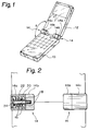
- FIG. 1 of the drawings a foldable electronic apparatus to which the present invention is applicable is shown and implemented as a hand-held mobile telephone by way of example.
- the telephone has a first casing 10 and a second casing 12 which are rotatably connected together by a pair of hinge mechanisms 14 having an identical configuration.
- the hinge mechanisms 14 each has a cylindrical first hinge 14a connected to the casing 10, and a cylindrical second hinge 14b connected to the casing 12.
- the hinges 14a and 14b are configured such that the casings 10 and 12 are locked in a position where they are spaced apart by a predetermined angle ⁇ .
- FIG. 2 shows a conventional arrangement of the first and second hinges 14a and 14b.
- the hinge 14a is provided with semispherical recesses 16 on the end thereof which faces the hinge 14b.
- the hinge 14b is provided with semispherical lugs 18 on the end thereof which faces the hinge 14a, the lugs 18 mating with the recesses 16.
- a cylindrical locking member 20 is received in the cylindrical hinge 14b and formed with the recesses 16 on the end thereof which faces the hinge 14b.
- a coil spring 22 is accommodated in the locking member 20 to constantly urge the member 20 against the hinge 14b via a screw 24. The problem with this kind of arrangement is that the bias of the spring 22 is difficult to set, as stated earlier.
- the hinge mechanism embodying the present invention has a cylindrical first hinge 14a and a cylindrical second hinge 14b.
- a pair of guide libs 26 (only one is visible) are provided on the inner periphery of the first hinge 14a and extend in the axial direction of the hinge 14a.
- Trapezoidal logs 28 are provided on the end of the second hinge 14b that faces the first hinge 14a.
- a cylindrical locking member 20 has guide grooves 30 each mating with one of the guide libs 26 on the outer periphery thereof.
- the locking member 20 has recesses 32 on the end thereof which faces the hinge 14b when the member 20 is inserted into the hinge 14a via a screw 24 and a spring 22.
- FIG. 4A is a front view showing the configuration of the lugs 28 of the hinge 14b in detail.
- the lugs 28 appear as shown in FIGS. 4B and 4C when seen from opposite sides.
- FIG. 5A shows the configurations of the recesses 32 and guide grooves 30 of the locking member 20 in detail.
- FIGS. 5A and 5B are side elevations of the recesses 32 and guide grooves 30 as viewed from opposite sides.
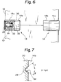
- each of the recesses 32 of the locking member 20 and the associated lug 28 of the second hinge 14b make contact angles ⁇ and ⁇ which are different from each other. For example, assume that when the two casings 10 and 12 are rotated toward each other, i.e., in the folding direction, the contact angle ⁇ holds.
- the contact angle ⁇ is selected to be greater than or equal to 45 degrees, the casings 10 and 12 can be rotated by a relatively small effort. Assume that the contact angle ⁇ holds when the casings 10 and 12 are urged further from the ordinary position for use in the unfolding direction. Then, if the contact angle ⁇ is selected to be smaller than 45 degrees ( ⁇ being smaller than ⁇ ), the casings 10 and 12 will be prevented from being unfolded more than the angle ⁇ .
- the present invention provides a hinge mechanism which allows each of the force for folding an electronic apparatus and the force for unfolding it to have a different value.
- the apparatus is easy to fold and is not unfoldable beyond the ordinary position for use unless an excessive force is inadvertently exerted thereon. This is successful in promoting easy operation of the apparatus and protecting the apparatus against damage.
Abstract
Description
- The present invention relates to the structure of a foldable electronic apparatus and, more particularly, to a hinge mechanism for a hand-held radio communication apparatus.
- A hand-held radio communication apparatus, e.g., a hand-held mobile telephone is one of portable electronic apparatuses extensively used today. For miniaturization, it is a common practice with such a hand-held radio communication apparatus to divide the casing thereof into two and connect the two casing parts by a hinge mechanism. In this configuration, the casing parts are rotatable about the hinge mechanism toward and away from each other, i.e., the apparatus is foldable. The casing parts are locked in a position where they are spaced apart by a predetermined angle by lugs ad recesses included in the hinge mechanism. To unlock the casing parts, a force greater than the bias of a spring also included in the hinge mechanism is exerted on the casing parts. The prerequisite with such a mechanism is that the bias of the spring be greater than the predetermined force associated with the predetermined angle, so that the mechanism may rotate beyond the predetermined angle only when a force greater than the predetermined force acts thereon. This brings about a problem that the apparatus cannot be folded or unfolded from or to the predetermined angle unless a force overcoming the bias of the spring is exerted. Should use be made of a spring exerting a relatively small bias to eliminate the above problem, the casing parts locked at the predetermined angle would be easily unlocked by a small effort.
- It is therefore an object of the present invention to provide a hinge mechanism for a foldable electronic apparatus which is easy to operate.
- It is another object of the present invention to provide a hinge mechanism for a foldable electronic apparatus which protects the apparatus from damage.
- A hinge mechanism for rotatably connecting a first and a second casing of a foldable electronic apparatus of the present invention comprises a first hinge provided on the first casing and having a first engaging portion, and a second hinge provided on the second casing and having a second engaging portion mating with the first engaging portion of the first hinge such that the first and second casings are locked in positions spaced apart by a predetermined angle from each other. The second engaging portion mates with the first engaging portion in a condition which differs from one direction of rotation to the other direction of rotation of the first and second casings.
- The above and other objects, features and advantages of the present invention will become more apparent from the following detailed description taken with the accompanying drawings in which:
- FIG. 1 is a perspective view of a foldable electronic apparatus to which the present invention is applicable;
- FIG. 2 is a sectional side elevation showing a conventional hinge mechanism;
- FIG. 3 is an exploded perspective view of a hinge mechanism embodying the present invention;
- FIG. 4A is a front view showing a second hinge included in the embodiment in detail;
- FIGS.4B and 4C are side elevations showing the second hinge as viewed from opposite sides;
- FIG. 5A is a front view of a locking member included in the embodiment;
- FIGS. 5B and 5C are side elevations of the locking member as viewed from opposite sides;
- FIG. 6 is a sectional side elevation showing a first hinge and the second hinge in a locking position;
- FIG. 7 is a fragmentary enlarged view showing the locking position of the hinge mechanism in more detail.
- Referring to FIG. 1 of the drawings, a foldable electronic apparatus to which the present invention is applicable is shown and implemented as a hand-held mobile telephone by way of example. As shown, the telephone has a
first casing 10 and asecond casing 12 which are rotatably connected together by a pair ofhinge mechanisms 14 having an identical configuration. Thehinge mechanisms 14 each has a cylindricalfirst hinge 14a connected to thecasing 10, and a cylindricalsecond hinge 14b connected to thecasing 12. Thehinges casings - FIG. 2 shows a conventional arrangement of the first and
second hinges hinge 14a is provided withsemispherical recesses 16 on the end thereof which faces thehinge 14b. On the other hand, thehinge 14b is provided withsemispherical lugs 18 on the end thereof which faces thehinge 14a, thelugs 18 mating with therecesses 16. More specifically, acylindrical locking member 20 is received in thecylindrical hinge 14b and formed with therecesses 16 on the end thereof which faces thehinge 14b. Acoil spring 22 is accommodated in thelocking member 20 to constantly urge themember 20 against thehinge 14b via ascrew 24. The problem with this kind of arrangement is that the bias of thespring 22 is difficult to set, as stated earlier. - A preferred embodiment of the hinge mechanism in accordance with the present invention which eliminates the above problem will be described hereinafter. In the embodiment, the same or similar constituents to the constituents of the mechanism shown in FIGS. 1 and 2 are designated by like reference numerals.
- Referring to FIG. 3, the hinge mechanism embodying the present invention has a cylindrical
first hinge 14a and a cylindricalsecond hinge 14b. A pair of guide libs 26 (only one is visible) are provided on the inner periphery of thefirst hinge 14a and extend in the axial direction of thehinge 14a.Trapezoidal logs 28 are provided on the end of thesecond hinge 14b that faces thefirst hinge 14a. Acylindrical locking member 20 has guidegrooves 30 each mating with one of theguide libs 26 on the outer periphery thereof. Also, thelocking member 20 has recesses 32 on the end thereof which faces thehinge 14b when themember 20 is inserted into thehinge 14a via ascrew 24 and aspring 22. Therecesses 32 each mates with one of thelugs 28 of thehinge 14b. FIG. 4A is a front view showing the configuration of thelugs 28 of thehinge 14b in detail. Thelugs 28 appear as shown in FIGS. 4B and 4C when seen from opposite sides. FIG. 5A shows the configurations of therecesses 32 and guidegrooves 30 of thelocking member 20 in detail. FIGS. 5A and 5B are side elevations of therecesses 32 and guidegrooves 30 as viewed from opposite sides. - As shown in FIG. 6, when the
recesses 20 of thefirst hinge 14a and thelugs 28 of thesecond hinge 14b mate with each other, thehinges hinges recesses 32 of thelocking member 20 and the associatedlug 28 of thesecond hinge 14b make contact angles α and β which are different from each other. For example, assume that when the twocasings casings casings casings - In summary, it will be seen that the present invention provides a hinge mechanism which allows each of the force for folding an electronic apparatus and the force for unfolding it to have a different value. Hence, the apparatus is easy to fold and is not unfoldable beyond the ordinary position for use unless an excessive force is inadvertently exerted thereon. This is successful in promoting easy operation of the apparatus and protecting the apparatus against damage.
- Various modifications will become possible for those skilled in the art after receiving the teachings of the present disclosure without departing from the scope thereof.
Claims (5)
- A hinge mechanism for rotatably connecting a first and a second casing of a foldable electronic apparatus, comprising:
first hinge means provided on the first casing and having first engaging means; and
second hinge means provided on the second casing and having second engaging means mating with said first engaging means of said first hinge means such that the first and second casings are locked in positions spaced apart by a predetermined angle from each other;
said second engaging means mating with said first engaging means in a condition which differs from one direction of rotation to the other direction of rotation of the first and second casings. - A hinge mechanism as claimed in claim 1, wherein said first hinge means comprises a cylindrical hinge member and a locking member received in said hinge member, said second hinge means comprising a cylindrical hinge member.
- A hinge mechanism as claimed in claim 2, wherein said first engaging means comprises recesses formed in one end of said locking member which faces said cylindrical hinge member of said second hinge means, said second engaging means comprising lugs formed on one end of said cylindrical hinge member which faces said one end of said locking member and each mating with one of said recesses of said locking member.
- A hinge mechanism as claimed in claim 3, wherein said lugs of said second engaging means each contacts one of said recesses of said first engaging means at a contact angle which differs from one direction of rotation to the other direction of rotation of the first and second casings.
- A hinge mechanism as claimed in claim 4, wherein assuming that the contact angle is α when the first and second casings are rotated in a folding direction, α is selected to be greater than or equal to 45 degrees while, assuming that the contact angle is β when said first and second casings are rotated in an unfolding direction, β is selected to be smaller than 45 degrees.
Applications Claiming Priority (2)
| Application Number | Priority Date | Filing Date | Title |
|---|---|---|---|
| JP78901/91U | 1991-09-30 | ||
| JP1991078901U JP2534114Y2 (en) | 1991-09-30 | 1991-09-30 | Foldable electronic device structure |
Publications (3)
| Publication Number | Publication Date |
|---|---|
| EP0535912A2 true EP0535912A2 (en) | 1993-04-07 |
| EP0535912A3 EP0535912A3 (en) | 1994-02-16 |
| EP0535912B1 EP0535912B1 (en) | 1998-06-24 |
Family
ID=13674732
Family Applications (1)
| Application Number | Title | Priority Date | Filing Date |
|---|---|---|---|
| EP92308869A Expired - Lifetime EP0535912B1 (en) | 1991-09-30 | 1992-09-29 | Hinge mechanism for foldable electronic apparatus |
Country Status (7)
| Country | Link |
|---|---|
| US (1) | US5317785A (en) |
| EP (1) | EP0535912B1 (en) |
| JP (1) | JP2534114Y2 (en) |
| KR (1) | KR950003838Y1 (en) |
| AU (1) | AU654394B2 (en) |
| CA (1) | CA2079388C (en) |
| DE (1) | DE69226006T2 (en) |
Cited By (21)
| Publication number | Priority date | Publication date | Assignee | Title |
|---|---|---|---|---|
| FR2721163A1 (en) * | 1994-06-09 | 1995-12-15 | Sagem | Electronic case with keyboard cover for pushbutton cordless telephone |
| FR2724737A1 (en) * | 1994-09-16 | 1996-03-22 | Tomy Co Ltd | TRANSFER DEVICE |
| EP0713313A1 (en) * | 1994-11-15 | 1996-05-22 | Nec Corporation | Foldable and portable telephone |
| WO1996017463A1 (en) * | 1994-11-28 | 1996-06-06 | Ericsson Inc. | Portable telephone with an asymmetric hinged housing configuration |
| EP0720339A2 (en) * | 1994-12-30 | 1996-07-03 | Nec Corporation | Electronic apparatus having a hinge structure |
| EP0756406A1 (en) * | 1995-07-27 | 1997-01-29 | Societe D'applications Generales D'electricite Et De Mecanique Sagem | Electronic easing with a hinged flap |
| FR2741766A1 (en) * | 1995-11-29 | 1997-05-30 | Philips Electronics Nv | TELEPHONE STATION COMPRISING A ROTATING STREAM |
| EP0801489A2 (en) * | 1996-04-11 | 1997-10-15 | Nokia Mobile Phones Ltd. | Hinge mechanism for fastening the two parts of a foldable apparatus to one another |
| EP0802293A1 (en) * | 1996-04-19 | 1997-10-22 | FIAT AUTO S.p.A. | A mechanical device for controlling the opening of a door |
| FR2752699A1 (en) * | 1996-09-03 | 1998-03-06 | Oreal | HOUSING, TYPE OF MAKE-UP HOUSING |
| WO1998040593A1 (en) * | 1997-03-13 | 1998-09-17 | Siemens Schweiz Ag | Device having a movable part |
| EP0927923A1 (en) * | 1998-01-05 | 1999-07-07 | Siemens Aktiengesellschaft | Hinge for a computer with telecommunication device and comprising a system unit, a keyboard unit, and a display unit |
| EP1006286A2 (en) * | 1998-12-03 | 2000-06-07 | Strawberry Corporation | Hinge device |
| FR2788892A1 (en) * | 1999-01-25 | 2000-07-28 | Framatome Connectors France | Mobile telephone rotating connection having fixed inner cavity holding flexible circuit with conductor tracks and rotating plug in unit with friction contact. |
| EP1093274A2 (en) * | 1999-10-15 | 2001-04-18 | Kabushiki Kaisha Strawberry Corporation | Hinge structure for collapsible portable phone |
| EP1113136A2 (en) * | 1999-12-28 | 2001-07-04 | Sugatsune Kogyo Co., Ltd. | Hinge assembly |
| EP1170517A1 (en) * | 1999-02-22 | 2002-01-09 | Strawberry Corporation | Hinge device and portable electronic device |
| US6633749B2 (en) * | 2000-08-04 | 2003-10-14 | Matsushita Electric Industrial Co. Ltd. | Folding mobile wireless device |
| DE102010020318A1 (en) * | 2010-05-10 | 2011-11-10 | Otto Bock Mobility Solutions Gmbh | Control unit for electric motor driven vehicles, in particular traction unit or pushing aid for a wheelchair or industrial truck |
| US8836585B2 (en) | 2008-12-22 | 2014-09-16 | Teknologian Tutkimuskeskus Vtt | Radio-frequency transponder for marking wood products and method of manufacturing thereof |
| CN111133167A (en) * | 2017-06-26 | 2020-05-08 | 惠普发展公司,有限责任合伙企业 | Cam with non-radial wear edge |
Families Citing this family (27)
| Publication number | Priority date | Publication date | Assignee | Title |
|---|---|---|---|---|
| JP2553924Y2 (en) * | 1992-02-20 | 1997-11-12 | 沖電気工業株式会社 | Rotating structure of flip phone |
| USD384059S (en) * | 1995-04-11 | 1997-09-23 | E.F. Johnson Company | Handheld two-way radio with hinged cover |
| US5678206A (en) * | 1995-04-12 | 1997-10-14 | E. F. Johnson Company | Keypad cover hinge |
| US5628089A (en) * | 1995-05-18 | 1997-05-13 | Motorola, Inc. | Radiotelephone having a self contained hinge |
| USD397109S (en) | 1995-08-25 | 1998-08-18 | E. F. Johnson Company | Handheld two-way radio with hinged cover |
| KR200141099Y1 (en) * | 1995-09-19 | 1999-05-15 | 김광호 | Button cover of a portable telephone |
| US5905796A (en) * | 1995-09-19 | 1999-05-18 | Samsung Electronics Co., Ltd. | Hinge mechanism for foldable electronic apparatus |
| DE19626704A1 (en) * | 1996-07-03 | 1998-01-08 | Scharwaechter Gmbh Co Kg | Motor vehicle door arrester |
| US5813093A (en) * | 1997-01-31 | 1998-09-29 | Lucent Technologies Inc. | Hinge assembly |
| JP3691630B2 (en) * | 1997-04-21 | 2005-09-07 | 加藤電機株式会社 | Opening and closing device for opening and closing body |
| US5966776A (en) * | 1997-05-07 | 1999-10-19 | Strawberry Corporation | Hinge device |
| US5996178A (en) * | 1997-10-15 | 1999-12-07 | Motorola, Inc. | Hinge suitable for use in a foldable device |
| US5996179A (en) * | 1998-08-07 | 1999-12-07 | Chin-Fu Huong & Li-Hua Liu | Device for preventing inadvertent pressing of push button keys |
| DE29815747U1 (en) * | 1998-09-02 | 2000-01-05 | Ramsauer Dieter | Screw-on hinge with locking position |
| JP4290989B2 (en) * | 2001-02-26 | 2009-07-08 | スガツネ工業株式会社 | Hinge device |
| TW530961U (en) * | 2002-02-20 | 2003-05-01 | Hannstar Display Corp | Stepwise pivot mechanism |
| FR2844434B1 (en) * | 2002-09-16 | 2004-11-05 | Techpack Int | PACKAGING OF COSMETIC PRODUCTS, TYPICALLY A HOUSING, TO BE SIDE CLOSED |
| US20040139579A1 (en) * | 2003-01-22 | 2004-07-22 | Ding-Hone Su | Axial rotary hinge assembly |
| US7062817B2 (en) * | 2003-03-14 | 2006-06-20 | Winia Mando, Inc. | Hinge assembly structure for opening and closing of door of storage facility |
| KR100651412B1 (en) * | 2003-10-31 | 2006-11-28 | 삼성전자주식회사 | Swing hinge device for portable terminal |
| US6986188B2 (en) * | 2004-06-14 | 2006-01-17 | Shin Zu Shing Co., Ltd. | Hinge |
| CA2550400C (en) | 2005-06-17 | 2014-02-11 | Columbia Insurance Company | Food grating device and improved hinge mechanism |
| DE202005014145U1 (en) | 2005-09-07 | 2006-03-02 | KL-Beschläge Karl Loggen GmbH | Hinge for doors or windows |
| DE102006037218B4 (en) * | 2006-08-09 | 2008-11-13 | Mekra Lang Gmbh & Co. Kg | Locking joint and outside mirror with such a locking joint |
| CN101742845B (en) * | 2008-11-20 | 2013-09-04 | 深圳富泰宏精密工业有限公司 | Hinge mechanism and portable electronic device using same |
| TWI447560B (en) * | 2008-12-05 | 2014-08-01 | Fih Hong Kong Ltd | Hinge assembly and portable electronic device using the same |
| US20100175501A1 (en) * | 2009-01-13 | 2010-07-15 | Chao-Chi Lin | Effort-Saving Cam Device of Hinge Assembly for Electronic Device |
Citations (4)
| Publication number | Priority date | Publication date | Assignee | Title |
|---|---|---|---|---|
| DE3723984A1 (en) * | 1986-07-21 | 1988-02-04 | Yazaki Corp | LID LOCKING MECHANISM FOR A MOTOR VEHICLE SWITCHBOARD PANEL DEVICE |
| US4774740A (en) * | 1986-04-23 | 1988-10-04 | Edward D. Gidseg | Door hinge |
| US4845809A (en) * | 1988-03-21 | 1989-07-11 | Pillifant Jr Albert | Leaf spring biased position retentive hinge assembly |
| EP0367610A2 (en) * | 1988-11-04 | 1990-05-09 | Motorola, Inc. | Multipurpose hinge apparatus for foldable telephones |
Family Cites Families (8)
| Publication number | Priority date | Publication date | Assignee | Title |
|---|---|---|---|---|
| US3874029A (en) * | 1974-01-16 | 1975-04-01 | Richard C Mccullough | Positive locking hinge |
| JPS625743A (en) * | 1985-07-01 | 1987-01-12 | Fujitsu Ltd | Semiconductor laser modulation circuit |
| US4623115A (en) * | 1985-11-12 | 1986-11-18 | Velvac, Inc. | Preset mirror mount |
| GB2192459B (en) * | 1986-07-07 | 1990-12-19 | English Electric Valve Co Ltd | Hydrogen sulphide sensor |
| AU624027B2 (en) * | 1989-10-11 | 1992-05-28 | Sugatsune Industrial Co., Ltd | Door hinge |
| JPH0486349A (en) * | 1990-07-26 | 1992-03-18 | Nissan Motor Co Ltd | Controller of internal combustion engine |
| WO1992017974A1 (en) * | 1991-03-28 | 1992-10-15 | Motorola, Inc. | Hinge apparatus for foldable radiotelephones |
| US5185790A (en) * | 1991-03-28 | 1993-02-09 | Motorola, Inc. | Multiposition detenting hinge apparatus |
-
1991
- 1991-09-30 JP JP1991078901U patent/JP2534114Y2/en not_active Expired - Lifetime
-
1992
- 1992-09-29 EP EP92308869A patent/EP0535912B1/en not_active Expired - Lifetime
- 1992-09-29 DE DE69226006T patent/DE69226006T2/en not_active Expired - Lifetime
- 1992-09-29 CA CA002079388A patent/CA2079388C/en not_active Expired - Fee Related
- 1992-09-29 AU AU26051/92A patent/AU654394B2/en not_active Expired
- 1992-09-29 KR KR92018524U patent/KR950003838Y1/en not_active IP Right Cessation
- 1992-09-30 US US07/954,348 patent/US5317785A/en not_active Expired - Lifetime
Patent Citations (4)
| Publication number | Priority date | Publication date | Assignee | Title |
|---|---|---|---|---|
| US4774740A (en) * | 1986-04-23 | 1988-10-04 | Edward D. Gidseg | Door hinge |
| DE3723984A1 (en) * | 1986-07-21 | 1988-02-04 | Yazaki Corp | LID LOCKING MECHANISM FOR A MOTOR VEHICLE SWITCHBOARD PANEL DEVICE |
| US4845809A (en) * | 1988-03-21 | 1989-07-11 | Pillifant Jr Albert | Leaf spring biased position retentive hinge assembly |
| EP0367610A2 (en) * | 1988-11-04 | 1990-05-09 | Motorola, Inc. | Multipurpose hinge apparatus for foldable telephones |
Cited By (38)
| Publication number | Priority date | Publication date | Assignee | Title |
|---|---|---|---|---|
| FR2721163A1 (en) * | 1994-06-09 | 1995-12-15 | Sagem | Electronic case with keyboard cover for pushbutton cordless telephone |
| BE1009538A5 (en) * | 1994-09-16 | 1997-05-06 | Tomy Co Ltd | Transfer device. |
| FR2724737A1 (en) * | 1994-09-16 | 1996-03-22 | Tomy Co Ltd | TRANSFER DEVICE |
| US5751477A (en) * | 1994-09-16 | 1998-05-12 | Tomy Company, Ltd. | Transferring device |
| EP0713313A1 (en) * | 1994-11-15 | 1996-05-22 | Nec Corporation | Foldable and portable telephone |
| WO1996017463A1 (en) * | 1994-11-28 | 1996-06-06 | Ericsson Inc. | Portable telephone with an asymmetric hinged housing configuration |
| US5732135A (en) * | 1994-11-28 | 1998-03-24 | Ericsson Inc. | Asymmetric hinged housing configuration |
| US5995373A (en) * | 1994-12-30 | 1999-11-30 | Nec Corporation | Electronic apparatus having a hinge structure |
| EP0720339A2 (en) * | 1994-12-30 | 1996-07-03 | Nec Corporation | Electronic apparatus having a hinge structure |
| EP0720339A3 (en) * | 1994-12-30 | 1999-02-24 | Nec Corporation | Electronic apparatus having a hinge structure |
| EP0756406A1 (en) * | 1995-07-27 | 1997-01-29 | Societe D'applications Generales D'electricite Et De Mecanique Sagem | Electronic easing with a hinged flap |
| FR2741766A1 (en) * | 1995-11-29 | 1997-05-30 | Philips Electronics Nv | TELEPHONE STATION COMPRISING A ROTATING STREAM |
| EP0777370A1 (en) * | 1995-11-29 | 1997-06-04 | Philips Electronique Grand Public | Portable telephone with a hinged cover |
| US5915440A (en) * | 1996-04-11 | 1999-06-29 | Nokia Mobile Phones Limited | Hinge mechanism for a foldable apparatus |
| EP0801489A3 (en) * | 1996-04-11 | 1998-02-04 | Nokia Mobile Phones Ltd. | Hinge mechanism for fastening the two parts of a foldable apparatus to one another |
| EP0801489A2 (en) * | 1996-04-11 | 1997-10-15 | Nokia Mobile Phones Ltd. | Hinge mechanism for fastening the two parts of a foldable apparatus to one another |
| EP0802293A1 (en) * | 1996-04-19 | 1997-10-22 | FIAT AUTO S.p.A. | A mechanical device for controlling the opening of a door |
| EP0832576A1 (en) * | 1996-09-03 | 1998-04-01 | L'oreal | Make-up container |
| FR2752699A1 (en) * | 1996-09-03 | 1998-03-06 | Oreal | HOUSING, TYPE OF MAKE-UP HOUSING |
| WO1998040593A1 (en) * | 1997-03-13 | 1998-09-17 | Siemens Schweiz Ag | Device having a movable part |
| EP0927923A1 (en) * | 1998-01-05 | 1999-07-07 | Siemens Aktiengesellschaft | Hinge for a computer with telecommunication device and comprising a system unit, a keyboard unit, and a display unit |
| EP1006286A2 (en) * | 1998-12-03 | 2000-06-07 | Strawberry Corporation | Hinge device |
| EP1006286A3 (en) * | 1998-12-03 | 2002-12-18 | Strawberry Corporation | Hinge device |
| FR2788892A1 (en) * | 1999-01-25 | 2000-07-28 | Framatome Connectors France | Mobile telephone rotating connection having fixed inner cavity holding flexible circuit with conductor tracks and rotating plug in unit with friction contact. |
| EP1170517A4 (en) * | 1999-02-22 | 2002-12-18 | Strawberry Corp | Hinge device and portable electronic device |
| US6823067B1 (en) | 1999-02-22 | 2004-11-23 | Strawberry Corporation | Hinge device and portable electronic device |
| EP1170517A1 (en) * | 1999-02-22 | 2002-01-09 | Strawberry Corporation | Hinge device and portable electronic device |
| EP1093274A3 (en) * | 1999-10-15 | 2004-02-11 | Kabushiki Kaisha Strawberry Corporation | Hinge structure for collapsible portable phone |
| EP1093274A2 (en) * | 1999-10-15 | 2001-04-18 | Kabushiki Kaisha Strawberry Corporation | Hinge structure for collapsible portable phone |
| EP1113136A3 (en) * | 1999-12-28 | 2003-05-21 | Sugatsune Kogyo Co., Ltd. | Hinge assembly |
| EP1113136A2 (en) * | 1999-12-28 | 2001-07-04 | Sugatsune Kogyo Co., Ltd. | Hinge assembly |
| US6633749B2 (en) * | 2000-08-04 | 2003-10-14 | Matsushita Electric Industrial Co. Ltd. | Folding mobile wireless device |
| US8836585B2 (en) | 2008-12-22 | 2014-09-16 | Teknologian Tutkimuskeskus Vtt | Radio-frequency transponder for marking wood products and method of manufacturing thereof |
| DE102010020318A1 (en) * | 2010-05-10 | 2011-11-10 | Otto Bock Mobility Solutions Gmbh | Control unit for electric motor driven vehicles, in particular traction unit or pushing aid for a wheelchair or industrial truck |
| EP2386470A1 (en) | 2010-05-10 | 2011-11-16 | Otto Bock Mobility Solutions GmbH | Operating unit for vehicles powered by electric motors, in particular traction unit or pushing aid for a wheelchair or industrial truck |
| DE102010020318B4 (en) * | 2010-05-10 | 2011-12-08 | Otto Bock Mobility Solutions Gmbh | Control unit for electric motor driven vehicles, in particular traction unit or pushing aid for a wheelchair or industrial truck |
| CN111133167A (en) * | 2017-06-26 | 2020-05-08 | 惠普发展公司,有限责任合伙企业 | Cam with non-radial wear edge |
| EP3645815A4 (en) * | 2017-06-26 | 2021-01-13 | Hewlett-Packard Development Company, L.P. | Cams with non-radial abrasion edges |
Also Published As
| Publication number | Publication date |
|---|---|
| KR930006886U (en) | 1993-04-24 |
| EP0535912B1 (en) | 1998-06-24 |
| KR950003838Y1 (en) | 1995-05-16 |
| EP0535912A3 (en) | 1994-02-16 |
| CA2079388C (en) | 1997-04-08 |
| AU654394B2 (en) | 1994-11-03 |
| DE69226006T2 (en) | 1998-12-17 |
| US5317785A (en) | 1994-06-07 |
| AU2605192A (en) | 1993-04-01 |
| JPH0531422U (en) | 1993-04-23 |
| JP2534114Y2 (en) | 1997-04-30 |
| DE69226006D1 (en) | 1998-07-30 |
Similar Documents
| Publication | Publication Date | Title |
|---|---|---|
| US5317785A (en) | Hinge mechanism for foldable electronic apparatus | |
| US6170120B1 (en) | Notebook computer hinge | |
| US6865406B2 (en) | Radiotelephone for visual communication | |
| US7383617B2 (en) | Hinge assembly | |
| US7634838B2 (en) | Hinge and a mobile phone with the hinge | |
| US5937062A (en) | Hinge module for mounting a flip onto a portable telephone set | |
| KR100480434B1 (en) | Camera lens assembly and portable wireless terminal therewith | |
| KR100450581B1 (en) | Hinge device and portable terminal therewith | |
| US20060112517A1 (en) | Hinge assembly for foldable electronic device | |
| US7512428B2 (en) | Twist-type mobile terminal and hinge device thereof | |
| US6859978B2 (en) | Flip phone having a hinge mechanism with an auto-lock function | |
| CN110714977A (en) | Folding device and electronic equipment | |
| US20050278894A1 (en) | Multi-section hinge mechanism | |
| US5271684A (en) | Rotatably mounted cable for communication equipment | |
| JP3119614B2 (en) | Foldable portable communication device | |
| JP2708011B2 (en) | Portable information equipment | |
| JP3853733B2 (en) | Foldable mobile phone | |
| JP3408496B2 (en) | Hinge structure of foldable equipment | |
| US20040254000A1 (en) | Folding electronic device | |
| KR100556886B1 (en) | Mobile terminal with function of fixing camera position | |
| JP2001313709A (en) | Holding mechanism for portable telephone set | |
| JP2003152348A (en) | Hinge structure of folding type terminal equipment | |
| KR20010000471U (en) | A electronic system having a infrared apparatus | |
| KR20050035721A (en) | Camera lens assembly for portable terminal | |
| KR20050054752A (en) | Portable terminal provided with a pair of hinge axis extended in parallel |
Legal Events
| Date | Code | Title | Description |
|---|---|---|---|
| PUAI | Public reference made under article 153(3) epc to a published international application that has entered the european phase |
Free format text: ORIGINAL CODE: 0009012 |
|
| AK | Designated contracting states |
Kind code of ref document: A2 Designated state(s): DE GB IT SE |
|
| PUAL | Search report despatched |
Free format text: ORIGINAL CODE: 0009013 |
|
| AK | Designated contracting states |
Kind code of ref document: A3 Designated state(s): DE GB IT SE |
|
| RHK1 | Main classification (correction) |
Ipc: H04M 1/02 |
|
| 17P | Request for examination filed |
Effective date: 19940113 |
|
| 17Q | First examination report despatched |
Effective date: 19961112 |
|
| GRAG | Despatch of communication of intention to grant |
Free format text: ORIGINAL CODE: EPIDOS AGRA |
|
| GRAG | Despatch of communication of intention to grant |
Free format text: ORIGINAL CODE: EPIDOS AGRA |
|
| GRAG | Despatch of communication of intention to grant |
Free format text: ORIGINAL CODE: EPIDOS AGRA |
|
| GRAG | Despatch of communication of intention to grant |
Free format text: ORIGINAL CODE: EPIDOS AGRA |
|
| GRAH | Despatch of communication of intention to grant a patent |
Free format text: ORIGINAL CODE: EPIDOS IGRA |
|
| GRAH | Despatch of communication of intention to grant a patent |
Free format text: ORIGINAL CODE: EPIDOS IGRA |
|
| GRAA | (expected) grant |
Free format text: ORIGINAL CODE: 0009210 |
|
| AK | Designated contracting states |
Kind code of ref document: B1 Designated state(s): DE GB IT SE |
|
| REF | Corresponds to: |
Ref document number: 69226006 Country of ref document: DE Date of ref document: 19980730 |
|
| PLBE | No opposition filed within time limit |
Free format text: ORIGINAL CODE: 0009261 |
|
| STAA | Information on the status of an ep patent application or granted ep patent |
Free format text: STATUS: NO OPPOSITION FILED WITHIN TIME LIMIT |
|
| 26N | No opposition filed | ||
| PGFP | Annual fee paid to national office [announced via postgrant information from national office to epo] |
Ref country code: SE Payment date: 20000919 Year of fee payment: 9 |
|
| PG25 | Lapsed in a contracting state [announced via postgrant information from national office to epo] |
Ref country code: SE Free format text: LAPSE BECAUSE OF NON-PAYMENT OF DUE FEES Effective date: 20010930 |
|
| REG | Reference to a national code |
Ref country code: GB Ref legal event code: IF02 |
|
| EUG | Se: european patent has lapsed |
Ref document number: 92308869.4 |
|
| PGFP | Annual fee paid to national office [announced via postgrant information from national office to epo] |
Ref country code: DE Payment date: 20100922 Year of fee payment: 19 |
|
| PGFP | Annual fee paid to national office [announced via postgrant information from national office to epo] |
Ref country code: GB Payment date: 20110928 Year of fee payment: 20 |
|
| PGFP | Annual fee paid to national office [announced via postgrant information from national office to epo] |
Ref country code: IT Payment date: 20110921 Year of fee payment: 20 |
|
| REG | Reference to a national code |
Ref country code: DE Ref legal event code: R071 Ref document number: 69226006 Country of ref document: DE |
|
| REG | Reference to a national code |
Ref country code: DE Ref legal event code: R071 Ref document number: 69226006 Country of ref document: DE |
|
| REG | Reference to a national code |
Ref country code: GB Ref legal event code: PE20 Expiry date: 20120928 |
|
| PG25 | Lapsed in a contracting state [announced via postgrant information from national office to epo] |
Ref country code: GB Free format text: LAPSE BECAUSE OF EXPIRATION OF PROTECTION Effective date: 20120928 |