EP0539659B1 - Decal transfer process - Google Patents
Decal transfer process Download PDFInfo
- Publication number
- EP0539659B1 EP0539659B1 EP92111201A EP92111201A EP0539659B1 EP 0539659 B1 EP0539659 B1 EP 0539659B1 EP 92111201 A EP92111201 A EP 92111201A EP 92111201 A EP92111201 A EP 92111201A EP 0539659 B1 EP0539659 B1 EP 0539659B1
- Authority
- EP
- European Patent Office
- Prior art keywords
- membrane
- decal
- heating
- accordance
- heated
- Prior art date
- Legal status (The legal status is an assumption and is not a legal conclusion. Google has not performed a legal analysis and makes no representation as to the accuracy of the status listed.)
- Expired - Lifetime
Links
Images

Classifications
-
- B—PERFORMING OPERATIONS; TRANSPORTING
- B44—DECORATIVE ARTS
- B44C—PRODUCING DECORATIVE EFFECTS; MOSAICS; TARSIA WORK; PAPERHANGING
- B44C1/00—Processes, not specifically provided for elsewhere, for producing decorative surface effects
- B44C1/16—Processes, not specifically provided for elsewhere, for producing decorative surface effects for applying transfer pictures or the like
- B44C1/165—Processes, not specifically provided for elsewhere, for producing decorative surface effects for applying transfer pictures or the like for decalcomanias; sheet material therefor
- B44C1/17—Dry transfer
- B44C1/1712—Decalcomanias applied under heat and pressure, e.g. provided with a heat activable adhesive
-
- B—PERFORMING OPERATIONS; TRANSPORTING
- B44—DECORATIVE ARTS
- B44C—PRODUCING DECORATIVE EFFECTS; MOSAICS; TARSIA WORK; PAPERHANGING
- B44C1/00—Processes, not specifically provided for elsewhere, for producing decorative surface effects
- B44C1/16—Processes, not specifically provided for elsewhere, for producing decorative surface effects for applying transfer pictures or the like
-
- Y—GENERAL TAGGING OF NEW TECHNOLOGICAL DEVELOPMENTS; GENERAL TAGGING OF CROSS-SECTIONAL TECHNOLOGIES SPANNING OVER SEVERAL SECTIONS OF THE IPC; TECHNICAL SUBJECTS COVERED BY FORMER USPC CROSS-REFERENCE ART COLLECTIONS [XRACs] AND DIGESTS
- Y10—TECHNICAL SUBJECTS COVERED BY FORMER USPC
- Y10T—TECHNICAL SUBJECTS COVERED BY FORMER US CLASSIFICATION
- Y10T156/00—Adhesive bonding and miscellaneous chemical manufacture
- Y10T156/11—Methods of delaminating, per se; i.e., separating at bonding face
- Y10T156/1168—Gripping and pulling work apart during delaminating
- Y10T156/1179—Gripping and pulling work apart during delaminating with poking during delaminating [e.g., jabbing, etc.]
-
- Y—GENERAL TAGGING OF NEW TECHNOLOGICAL DEVELOPMENTS; GENERAL TAGGING OF CROSS-SECTIONAL TECHNOLOGIES SPANNING OVER SEVERAL SECTIONS OF THE IPC; TECHNICAL SUBJECTS COVERED BY FORMER USPC CROSS-REFERENCE ART COLLECTIONS [XRACs] AND DIGESTS
- Y10—TECHNICAL SUBJECTS COVERED BY FORMER USPC
- Y10T—TECHNICAL SUBJECTS COVERED BY FORMER US CLASSIFICATION
- Y10T156/00—Adhesive bonding and miscellaneous chemical manufacture
- Y10T156/17—Surface bonding means and/or assemblymeans with work feeding or handling means
- Y10T156/1702—For plural parts or plural areas of single part
- Y10T156/1705—Lamina transferred to base from adhered flexible web or sheet type carrier
- Y10T156/1707—Discrete spaced laminae on adhered carrier
- Y10T156/171—Means serially presenting discrete base articles or separate portions of a single article
-
- Y—GENERAL TAGGING OF NEW TECHNOLOGICAL DEVELOPMENTS; GENERAL TAGGING OF CROSS-SECTIONAL TECHNOLOGIES SPANNING OVER SEVERAL SECTIONS OF THE IPC; TECHNICAL SUBJECTS COVERED BY FORMER USPC CROSS-REFERENCE ART COLLECTIONS [XRACs] AND DIGESTS
- Y10—TECHNICAL SUBJECTS COVERED BY FORMER USPC
- Y10T—TECHNICAL SUBJECTS COVERED BY FORMER US CLASSIFICATION
- Y10T156/00—Adhesive bonding and miscellaneous chemical manufacture
- Y10T156/19—Delaminating means
- Y10T156/1978—Delaminating bending means
- Y10T156/1983—Poking delaminating means
Definitions
- the field is apparatus and method for transfer and application of offset heat release decals.
- Heat release decals customarily include a design layer supported on a substrate which is usually a paper sheet.
- An intermediate adhesive layer may be provided between the design layer and the paper sheet. That layer is solid at ambient temperature and softenable when heated. This permits separation of the design layer and the paper sheet, either during pickup of the decal or after its application to an article being decorated.
- Heat release decals as well as equipment for their application to ware, have been in use for many years. This is especially true for direct applied decals. There, the decal is brought into contact with the ware being decorated, and the design layer is applied by heat and contact pressure. Pressure may be applied by a rubber roller or pressure pad. Heat may be supplied by a heated pressure or print pad, for example, by an electrically heated pad. Alternatively, heat may be supplied by preheated ware.
- the design layer must separate from the carrier paper during pickup. This means that the temperature of the decal must be raised sufficiently to soften the adhesive layer. However, the adhesive must not become so hot that it becomes too fluid. It is evident that close temperature control must be exercised.
- the transfer pad presents even more of a problem.
- the pad is normally of substantial size such that its temperature cannot be quickly changed.
- the pad temperature must be sufficiently high so that the pad does not act as a heat sink and freeze the adhesive layer.
- some heat will be lost during transfer, and even more as the decal is applied to the ware.
- the ware of course, will be at ambient temperature to freeze the adhesive on the surface of the ware, thereby permitting release of the decal from the pressure pad.
- the material problem is one of selecting a suitable silicone material for the silicone transfer pad.
- the silicone must be relatively soft and deformable, that is, have a low durometer reading. This is necessary to avoid ware fracture when pressure is applied during decal application.
- most silicone materials of this nature do not have good release properties. In summary then, the problem is effecting a compromise between good chemical properties for decal release and good physical properties to avoid ware damage.
- the apparatus of my invention includes
- the silicone membrane may be 0.040 to 0.100" (0.10-0.25 cm) thick. It may be heated by a heated platen, or by focused infra-red heating means.
- a single print head may be employed to apply pressure through the silicone membrane for the decal pickup and also for printing the decal on the ware. However, it is preferred to provide a separate print head for each operation and to heat each head.
- the invention further resides in a method of applying an offset, heat release decal to an article surface which includes the steps of
- U.S. No. 2,077,790 (Hakogi) describes an offset printing apparatus in which a blanket carries an ink pattern, the blanket is pressed into a bowl to be decorated and air is evacuated between the blanket and the bowl.
- U.S. No. 4,392,905 (Boyd et al.) describes a laminate carried by a paper support, and application of the laminate to an article by a heated, silicone rubber transfer pad.
- the laminate support is heated to a temperature of 390°-420°F (199°-216°C) to soften an adhesive layer, and the transfer pad is heated to a lower temperature of 300-350°F (149°-177°C).
- U.S. No. 4,532,175 (Johnson et al.) describes a silicone membrane for use in collecting and transferring an ink design.
- the membrane is preferably 0.030 to 0.090" (0.075 to 0.225 cms) thick and has other defined release characteristics.
- My invention resides in an apparatus for, and method of, applying an offset, heat release decal to an article.
- a key feature is the use of a thin, flexible, silicone membrane as a mechanism for picking up, transferring and printing a decal on an article.
- the silicone membrane is preferably in the range of 0.040 to 0.100" (0.10-0.25 cm) thick. Because of its thin nature, the durometer of the silicone is not critical, as it is in prior printing pads. Rather, the silicone for the membrane may be selected on the basis of optimum release characteristics.
- a basic concept of the invention is physical separation of the thin, silicone membrane from a relatively bulky print or press pad.
- the print pad is still required in applying pressure through the membrane.
- the two members are physically separated so that critical temperature control is exercised in the membrane, not in the print pad.
- FIGURE 1 is a schematic drawing showing a four-position, indexing membrane table.
- the membrane in each of the four positions, is mounted with the print surface facing down.
- Position A is a membrane heater position.
- Position B is a decal pickup position.
- Position C is a decal print position where the decal is brought to, and printed on, the ware.
- Position D is optional, and is a position where additional membrane heating and/or cleaning may occur.
- FIGURES 2-5 The elements involved, and the functions carried out at positions A-D, are detailed in FIGURES 2-5, respectively.
- FIGURES 2a and 2b are schematic views in cross-section. They illustrate alternative heating systems for membrane 10 in position A.
- Membrane 10 is a thin silicone member, usually circular in nature, which is mounted on member 12.
- Member 12 is shown as a metal ring that rests in an opening 14 in membrane table 16.
- Table 16 may have any suitable geometry, but is shown as a square, movable, flat sheet of any suitable material.
- FIGURE 2a illustrates a simple system employing a temperature-controlled platen 18.
- Platen 18 may, for example, be electrically heated. It may be controlled at a temperature determined to be adequate for quick reheating of the membrane after each cycle. Heated platen 18 is mounted close to the under surface of membrane 10, but with sufficient clearance to permit indexing of membrane table 16.
- FIGURE 2b shows an alternative heating system.
- Membrane 10 may be mounted as in FIGURE 2a. However, heated platen 18 is replaced by infra-red heaters 20. Heaters 20 will also be controlled to bring membrane 10 to a fixed temperature at position A. The surface temperature of membrane 10 may be monitored by an optical pyrometer 22. In order to conserve and focus the heat generated, heaters 20 may be surrounded by a shroud-like enclosure 24.
- membrane table 16 is indexed from position A to position B preparatory to picking up a decal for printing.
- a decal loader system 26 includes a decal magazine 28 from which a decal 30 is picked up by suction cups 32 and carried forward to a heated vacuum platen 34. The decal is released to platen 34 where it is held in place by vacuum means (not shown). Platen 34, carrying decal 30, then slides into position under membrane table assembly 16 and presshead assembly 36. This is shown in a schematic cross-section view in FIGURE 3.
- Presshead assembly 36 is a conventional component that has a cross arm construction, as shown, for vertical operation.
- Assembly 36 has a sheet 38 carried by vertical post 40 that serves as a carrier for presshead 42.
- the latter is composed of a deformable silicone.
- Decal 30 in turn, is heated by platen 34 to soften an adhesive layer between the design layer and the decal backing. This permits separation to occur readily.
- Platen 34 may correspond to platen 18 in FIGURE 2a. It operates at a set temperature. This temperature control, together with a controlled dwell time, ensures optimum conditions in decal 30 for its pickup by membrane 10.
- presshead 42 As presshead 42 is lowered against membrane 10, the latter is deformed and pressed into contact with decal 30.
- the dwell time of presshead 42 is controlled, after which the presshead is retracted. This releases the pressure on membrane 10, thereby allowing it to regain its shape and lift the design layer of decal 30 away from its paper backing.
- Membrane table 16 then indexes to position C. Meanwhile, decal platen 34 retracts and the spent paper backing is removed preparatory to starting another cycle.
- FIGURE 4 is a schematic view in cross-section showing membrane table 16 indexed to position C with membrane 10 carrying decal 30.
- FIGURE 4 also shows the arrangement for transfer of decal 30 to an article 44.
- article 44 e.g., a dinner plate
- Chuck 46 embodies a centering device 48 to hold article 44 in a fixed position.
- the assembly 50 is moved laterally on a track 52. This positions assembly 50 in alignment with a presshead assembly 54 and membrane 10.
- Presshead assembly 54 is similar in structure and operation to assembly 36 of FIGURE 3.
- the operative element is presshead 56 which, like presshead 42, is composed of a deformable silicone rubber.
- presshead assembly 54 With article 44 in position, presshead assembly 54 is lowered to bring presshead 56 into contact with membrane 10. Further downward movement of assembly 54 deforms membrane 10 and presses decal 30 into contact with ware 44.
- a dwell timer operates to maintain contact pressure until the transfer of decal 30 is complete. Presshead assembly 54 then retracts to its inoperative position. At the same time, the ware assembly 50 moves back to its out position from unloading article 44 and loading of another article for another print cycle. Meanwhile membrane table 16 is indexed to position D.
- position D may be a combined preheat and cleaning station.
- a third presshead assembly 58 similar to previous assemblies 42 and 54, and a heated platen 60, similar to heated platens 18 and 34, are provided. Platen 60 serves to heat the membrane 10 for cleaning. It also reduces the heating time required in position A.
- Presshead assembly 58 may be lowered to deform membrane 10. This presses membrane 10 against a cleaning material 62 which may be rolled over platen 60. A continuous roll of paper 62, passing between rolls 64, has been found successful to remove any decal residue from the membrane. After a fixed dwell time, presshead assembly 58 is retracted. Membrane table 16, with a clean and preheated membrane 10, is then indexed to position A to begin a new cycle.
- An essential feature of my invention then is use of a thin silicone membrane as a pickup and print member. Necessarily, the membrane is used in conjunction with a means of applying pressure, such as the presshead assemblies shown. However, the membrane is a separate and distinct member that can be controlled independent of the presshead.
- the characteristics of the presshead and the membrane may be optimized separately, that is, each for its inherent function.
- the primary concern will be release characteristics that are of a chemical nature. Because the membrane is so thin, physical properties, in particular the durometer of the material, are of secondary concern at most.
- a soft, deformable material may be preferred for the presshead.
- a preferred presshead material is a deformable silicone rubber with a durometer of about 30-40 on the Shore-00 scale.
- a membrane material that has excellent release characteristics, but has a durometer of about 60-70.
- a further feature of the invention is use of membrane and decal heating systems.
- the use of closely controllable heating systems permit determining and employing optimum temperature conditions for each stage of the operation.
- the decal is heated to a temperature where separation at the adhesive layer occurs most readily.
- Heating of the membrane means that it is at an optimum temperature for decal pickup.
- heating of the presshead while not so critical, does avoid it acting as a heat sink.
- the use of a thin membrane, controlled separately from the presshead, is significant with respect to temperature control. The membrane can be more quickly heated, or reheated, whereby the cycle is speeded up.
- a single presshead assembly might be used for all positions. It might be indexed in conjunction with the membrane table. The operation would, of course, be slower, but the apparatus would be simplified.
- position D is an optional operation. If cleaning and/or reheating of the membrane should prove unnecessary, this position might be omitted.
- a three-position table might then be used. However, the four-position table is preferred to speed up the cycle and increase the select rate of good ware.
Description
- The field is apparatus and method for transfer and application of offset heat release decals.
- Heat release decals customarily include a design layer supported on a substrate which is usually a paper sheet. An intermediate adhesive layer may be provided between the design layer and the paper sheet. That layer is solid at ambient temperature and softenable when heated. This permits separation of the design layer and the paper sheet, either during pickup of the decal or after its application to an article being decorated.
- Heat release decals, as well as equipment for their application to ware, have been in use for many years. This is especially true for direct applied decals. There, the decal is brought into contact with the ware being decorated, and the design layer is applied by heat and contact pressure. Pressure may be applied by a rubber roller or pressure pad. Heat may be supplied by a heated pressure or print pad, for example, by an electrically heated pad. Alternatively, heat may be supplied by preheated ware.
- Recently, an offset heat release decal process has been proposed where the decal is preheated on a platen, see e.g. GB-A-2 193 158. The design layer of the preheated decal is picked up from the decal paper substrate by a silicone print pad, The design layer is then transferred to the ware and applied by pressing the silicone print pad into contact with the ware. A feature of such a process is ability to design the print pad for use with curved or otherwise irregular surfaces.
- Such a process holds forth much promise. However, certain problems limit its use. These involve primarily temperature control and material selection.
- The design layer must separate from the carrier paper during pickup. This means that the temperature of the decal must be raised sufficiently to soften the adhesive layer. However, the adhesive must not become so hot that it becomes too fluid. It is evident that close temperature control must be exercised.
- The transfer pad presents even more of a problem. The pad is normally of substantial size such that its temperature cannot be quickly changed. During decal pickup, the pad temperature must be sufficiently high so that the pad does not act as a heat sink and freeze the adhesive layer. However, some heat will be lost during transfer, and even more as the decal is applied to the ware. The ware, of course, will be at ambient temperature to freeze the adhesive on the surface of the ware, thereby permitting release of the decal from the pressure pad.
- The net effect is that the transfer pad must be reheated between cycles. Because of its substantial size, this is relatively time consuming. This slows the rate at which the machine can be operated.
- The material problem is one of selecting a suitable silicone material for the silicone transfer pad. On the one hand, the silicone must be relatively soft and deformable, that is, have a low durometer reading. This is necessary to avoid ware fracture when pressure is applied during decal application. However, most silicone materials of this nature do not have good release properties. In summary then, the problem is effecting a compromise between good chemical properties for decal release and good physical properties to avoid ware damage.
- It is a basic purpose of my invention to provide a novel apparatus and process for offset heat release decal application that avoids the problems just discussed. Another purpose is to provide an apparatus and process where transfer of the decal is less dependent on the nature of the pressure pad.
- The apparatus of my invention includes
- a plurality of work positions,
- a thin, silicone membrane carried by a support member,
- means for indexing the membrane and support member through successive work positions,
- means for heating the membrane at a first work position,
- means for presenting a decal for pickup by the heated membrane at a second work position,
- means for bringing the membrane and decal into close proximity to an article at a third work position and
- means for applying pressure through the membrane to print the decal on the surface of the article.
- In one embodiment, the silicone membrane may be 0.040 to 0.100" (0.10-0.25 cm) thick. It may be heated by a heated platen, or by focused infra-red heating means. A single print head may be employed to apply pressure through the silicone membrane for the decal pickup and also for printing the decal on the ware. However, it is preferred to provide a separate print head for each operation and to heat each head.
- The invention further resides in a method of applying an offset, heat release decal to an article surface which includes the steps of
- supporting a thin, silicone membrane at the membrane periphery,
- indexing the supported membrane through successive work positions,
- heating the membrane to a predetermined temperature at a first position,
- presenting a decal for pickup by the membrane at a second position,
- heating the decal to a predetermined temperature,
- bringing the membrane into contact with the heated decal to pick the decal up on the membrane,
- bringing the decal on the membrane into contact with the article surface and
- releasing the decal from the membrane onto the article surface.
- Attention is directed to the following patents as illustrating the state of the art:
- U.S. No. 2,077,790 (Hakogi) describes an offset printing apparatus in which a blanket carries an ink pattern, the blanket is pressed into a bowl to be decorated and air is evacuated between the blanket and the bowl.
- U.S. No. 4,392,905 (Boyd et al.) describes a laminate carried by a paper support, and application of the laminate to an article by a heated, silicone rubber transfer pad. The laminate support is heated to a temperature of 390°-420°F (199°-216°C) to soften an adhesive layer, and the transfer pad is heated to a lower temperature of 300-350°F (149°-177°C).
- U.S. No. 4,532,175 (Johnson et al.) describes a silicone membrane for use in collecting and transferring an ink design. The membrane is preferably 0.030 to 0.090" (0.075 to 0.225 cms) thick and has other defined release characteristics.
- British No. 2,081,645 (Clare) describes a transfer apparatus that employs a vacuum pickup, and that heats a decal with an electric heating element for release.
- British No. 2,193,158 (Pass) describes an apparatus including a heated platen to soften the adhesive layer in a decal for removal of the backing, and a deformable, heated transfer pad.
- In the accompanying drawings,
- FIGURE 1 is a schematic top view of a four-position, indexing table in accordance with the invention.
- FIGURE 2a is a schematic view in cross-section taken at position A of FIGURE 1.
- FIGURE 2b is a schematic view in cross-section that is similar to FIGURE 2a, but illustrates an alternative heating system.
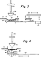
- FIGURE 3 is a schematic view in cross-section taken at position B of FIGURE 1.
- FIGURE 4 is a schematic view in cross-section taken at position C of FIGURE 1.
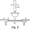
- FIGURE 5 is a schematic view in cross-section taken at position D of FIGURE 1.
- My invention resides in an apparatus for, and method of, applying an offset, heat release decal to an article. A key feature is the use of a thin, flexible, silicone membrane as a mechanism for picking up, transferring and printing a decal on an article. The silicone membrane is preferably in the range of 0.040 to 0.100" (0.10-0.25 cm) thick. Because of its thin nature, the durometer of the silicone is not critical, as it is in prior printing pads. Rather, the silicone for the membrane may be selected on the basis of optimum release characteristics.
- A basic concept of the invention is physical separation of the thin, silicone membrane from a relatively bulky print or press pad. The print pad is still required in applying pressure through the membrane. However, the two members are physically separated so that critical temperature control is exercised in the membrane, not in the print pad. This will become more apparent as the invention is further described with reference to the accompanying drawings.
- FIGURE 1 is a schematic drawing showing a four-position, indexing membrane table. In this FIGURE, the membrane, in each of the four positions, is mounted with the print surface facing down. Position A is a membrane heater position. Position B is a decal pickup position. Position C is a decal print position where the decal is brought to, and printed on, the ware. Position D is optional, and is a position where additional membrane heating and/or cleaning may occur. The elements involved, and the functions carried out at positions A-D, are detailed in FIGURES 2-5, respectively.
- FIGURES 2a and 2b are schematic views in cross-section. They illustrate alternative heating systems for
membrane 10 inposition A. Membrane 10 is a thin silicone member, usually circular in nature, which is mounted onmember 12.Member 12 is shown as a metal ring that rests in an opening 14 in membrane table 16. Table 16 may have any suitable geometry, but is shown as a square, movable, flat sheet of any suitable material. - It is necessary to uniformly and rapidly heat the under surface of
membrane 10 to a fixed, set-point temperature. The absolute value of that temperature will vary with, and depend on, the heat release decal construction and materials. - FIGURE 2a illustrates a simple system employing a temperature-controlled
platen 18.Platen 18 may, for example, be electrically heated. It may be controlled at a temperature determined to be adequate for quick reheating of the membrane after each cycle.Heated platen 18 is mounted close to the under surface ofmembrane 10, but with sufficient clearance to permit indexing of membrane table 16. - FIGURE 2b shows an alternative heating system.
Membrane 10 may be mounted as in FIGURE 2a. However,heated platen 18 is replaced by infra-red heaters 20. Heaters 20 will also be controlled to bringmembrane 10 to a fixed temperature at position A. The surface temperature ofmembrane 10 may be monitored by anoptical pyrometer 22. In order to conserve and focus the heat generated, heaters 20 may be surrounded by a shroud-like enclosure 24. - Referring back to FIGURE 1, membrane table 16 is indexed from position A to position B preparatory to picking up a decal for printing. At position B, a
decal loader system 26 includes adecal magazine 28 from which adecal 30 is picked up bysuction cups 32 and carried forward to aheated vacuum platen 34. The decal is released to platen 34 where it is held in place by vacuum means (not shown).Platen 34, carryingdecal 30, then slides into position undermembrane table assembly 16 and presshead assembly 36. This is shown in a schematic cross-section view in FIGURE 3. - Presshead assembly 36 is a conventional component that has a cross arm construction, as shown, for vertical operation. Assembly 36 has a
sheet 38 carried byvertical post 40 that serves as a carrier forpresshead 42. The latter is composed of a deformable silicone. When press-head 42 is lowered againstmembrane 10, the membrane is depressed againstdecal 30 to pickup the decal. -
Decal 30, in turn, is heated byplaten 34 to soften an adhesive layer between the design layer and the decal backing. This permits separation to occur readily.Platen 34 may correspond to platen 18 in FIGURE 2a. It operates at a set temperature. This temperature control, together with a controlled dwell time, ensures optimum conditions indecal 30 for its pickup bymembrane 10. - As
presshead 42 is lowered againstmembrane 10, the latter is deformed and pressed into contact withdecal 30. The dwell time ofpresshead 42 is controlled, after which the presshead is retracted. This releases the pressure onmembrane 10, thereby allowing it to regain its shape and lift the design layer ofdecal 30 away from its paper backing. Membrane table 16 then indexes to position C. Meanwhile,decal platen 34 retracts and the spent paper backing is removed preparatory to starting another cycle. - FIGURE 4 is a schematic view in cross-section showing membrane table 16 indexed to position C with
membrane 10 carryingdecal 30. FIGURE 4 also shows the arrangement for transfer ofdecal 30 to anarticle 44. In this arrangement,article 44, e.g., a dinner plate, is loaded in avacuum chuck 46.Chuck 46 embodies a centeringdevice 48 to holdarticle 44 in a fixed position. Afterarticle 44 is loaded inchuck 46, theassembly 50 is moved laterally on atrack 52. This positionsassembly 50 in alignment with apresshead assembly 54 andmembrane 10. -
Presshead assembly 54 is similar in structure and operation to assembly 36 of FIGURE 3. The operative element is presshead 56 which, likepresshead 42, is composed of a deformable silicone rubber. Witharticle 44 in position,presshead assembly 54 is lowered to bringpresshead 56 into contact withmembrane 10. Further downward movement ofassembly 54 deformsmembrane 10 and pressesdecal 30 into contact withware 44. A dwell timer operates to maintain contact pressure until the transfer ofdecal 30 is complete.Presshead assembly 54 then retracts to its inoperative position. At the same time, theware assembly 50 moves back to its out position from unloadingarticle 44 and loading of another article for another print cycle. Meanwhile membrane table 16 is indexed to position D. - As shown in FIGURE 5, position D may be a combined preheat and cleaning station. A
third presshead assembly 58, similar toprevious assemblies heated platen 60, similar toheated platens Platen 60 serves to heat themembrane 10 for cleaning. It also reduces the heating time required in position A. -
Presshead assembly 58 may be lowered to deformmembrane 10. This pressesmembrane 10 against a cleaningmaterial 62 which may be rolled overplaten 60. A continuous roll ofpaper 62, passing betweenrolls 64, has been found successful to remove any decal residue from the membrane. After a fixed dwell time,presshead assembly 58 is retracted. Membrane table 16, with a clean andpreheated membrane 10, is then indexed to position A to begin a new cycle. - An essential feature of my invention then is use of a thin silicone membrane as a pickup and print member. Necessarily, the membrane is used in conjunction with a means of applying pressure, such as the presshead assemblies shown. However, the membrane is a separate and distinct member that can be controlled independent of the presshead.
- A primary significance of this distinction is that the characteristics of the presshead and the membrane may be optimized separately, that is, each for its inherent function. In choosing a membrane material, the primary concern will be release characteristics that are of a chemical nature. Because the membrane is so thin, physical properties, in particular the durometer of the material, are of secondary concern at most.
- The physical properties are of significance in selecting the material for a presshead. To avoid crushing or breaking of thin ware, a soft, deformable material may be preferred for the presshead. By way of illustration, I have found that a preferred presshead material is a deformable silicone rubber with a durometer of about 30-40 on the Shore-00 scale. In contrast, I prefer a membrane material that has excellent release characteristics, but has a durometer of about 60-70.
- A further feature of the invention is use of membrane and decal heating systems. In particular, the use of closely controllable heating systems permit determining and employing optimum temperature conditions for each stage of the operation. Thus, the decal is heated to a temperature where separation at the adhesive layer occurs most readily. Heating of the membrane means that it is at an optimum temperature for decal pickup. Also, heating of the presshead, while not so critical, does avoid it acting as a heat sink. The use of a thin membrane, controlled separately from the presshead, is significant with respect to temperature control. The membrane can be more quickly heated, or reheated, whereby the cycle is speeded up.
- Within these basic considerations, numerous variations and modifications are contemplated. With the foregoing teaching as a guide, these will be readily evident to those conversant with the decal and decorating arts.
- In particular, it is contemplated that a single presshead assembly might be used for all positions. It might be indexed in conjunction with the membrane table. The operation would, of course, be slower, but the apparatus would be simplified.
- Also, as indicated earlier, position D is an optional operation. If cleaning and/or reheating of the membrane should prove unnecessary, this position might be omitted. A three-position table might then be used. However, the four-position table is preferred to speed up the cycle and increase the select rate of good ware.
Claims (10)
- An apparatus for applying an offset, heat release decal to the surface of an article, the apparatus includinga plurality of work positions (A, B, C, D),a thin, silicone membrane (10) carried by a support member (12),means (16) for indexing the membrane (10) and support member (12) through successive work positions (A, B, C, D),means (18, 20) for heating the membrane (10) at a first work position (A),means (34) for presenting a decal (30) for pickup by the heated membrane (10) at a second work position (B),means (50) for bringing the membrane (10) and decal (30) into close proximity to an article (44) at a third work position (C) andmeans (5) for applying pressure through the membrane (10) to print the decal (30) on the surface of the article (44).
- An apparatus in accordance with claim 1 wherein the silicone membrane is 0.040 to 0.100" (0.10-0.25 cm) thick.
- An apparatus in accordance with claim 1 wherein the means for heating the membrane at the first position is a heated platen in close proximity to the membrane, or wherein the means for heating the membrane at the first position includes infra-red heaters in close proximity to the membrane.
- An apparatus in accordance with claim 1, 2 or 3 wherein the means for presenting the decal for pickup is a vacuum device.
- An apparatus in accordance with claim 1, 2, 3 or 4 further including means for heating the decal to a predetermined temperature at the second work position.
- An apparatus in accordance with any one of claims 1-5 further including means for applying pressure against the membrane to press it into contact with the decal at the second position, optionally said means for applying pressure against the membrane being indexed in conjunction with the membrane.
- An apparatus in accordance with any one of claims 1-6 further including a fourth work position having means for removing decal residue from the membrane, said fourth work position optionally further including means for heating the membrane.
- A method of applying an offset, heat release decal to an article surface which includes the steps ofsupporting a thin, silicone membrane at the membrane periphery,indexing the supported membrane through successive work positions,heating the membrane to a predetermined temperature at a first position,presenting a decal for pickup by the membrane at a second position,heating the decal to a predetermined temperature,bringing the membrane into contact with the heated decal to pick the decal up on the membrane,bringing the decal on the membrane into contact with the article surface andreleasing the decal from the membrane onto the article surface.
- A method in accordance with claim 8 wherein the decal presented at the second work position is attached to a backing by an adhesive layer and the decal is heated to a temperature such that the adhesive layer softens but does not flow.
- A method in accordance with claim 8 or 9 which includes applying pressure against the membrane at the second work position to force the membrane into contact with the heated decal, and/or applying pressure against the membrane at the third work position to force the decal into contact with the article surface, optionally including step of preheating the silicone membrane, and/or optionally including as a further step of cleaning decal residue from the silicone membrane at a fourth work position.
Applications Claiming Priority (2)
| Application Number | Priority Date | Filing Date | Title |
|---|---|---|---|
| US78386391A | 1991-10-28 | 1991-10-28 | |
| US783863 | 1991-10-28 |
Publications (3)
| Publication Number | Publication Date |
|---|---|
| EP0539659A2 EP0539659A2 (en) | 1993-05-05 |
| EP0539659A3 EP0539659A3 (en) | 1994-04-27 |
| EP0539659B1 true EP0539659B1 (en) | 1997-03-12 |
Family
ID=25130636
Family Applications (1)
| Application Number | Title | Priority Date | Filing Date |
|---|---|---|---|
| EP92111201A Expired - Lifetime EP0539659B1 (en) | 1991-10-28 | 1992-07-02 | Decal transfer process |
Country Status (4)
| Country | Link |
|---|---|
| US (1) | US5300170A (en) |
| EP (1) | EP0539659B1 (en) |
| JP (1) | JP2923126B2 (en) |
| DE (1) | DE69218107T2 (en) |
Families Citing this family (26)
| Publication number | Priority date | Publication date | Assignee | Title |
|---|---|---|---|---|
| US5637172A (en) * | 1994-08-15 | 1997-06-10 | Earth & Ocean Sports, Inc. | Method for applying a decal to foam |
| US5630894A (en) * | 1995-02-23 | 1997-05-20 | Gemstone Memorials, Inc. | Flexible heating pad for transfer of decalcomania |
| IT1274381B (en) * | 1995-04-21 | 1997-07-17 | I P A Ind Porcellane S P A | MACHINE FOR THE DECORATION OF MUGS AND OTHER CERAMIC ARTICLES WITH COMPLEX CONFORMATION, BY HOT TRANSFER OF DECALS |
| DE19814101A1 (en) * | 1998-03-30 | 1999-10-14 | Fresenius Medical Care De Gmbh | Process for the airtight connection of two membranes |
| DE10006176A1 (en) * | 2000-02-11 | 2001-08-16 | Schenck Rotec Gmbh | Device for attaching balance weights for balancing |
| US6499526B1 (en) * | 2000-10-11 | 2002-12-31 | The United States Of America As Represented By The Secretary Of The Navy | Umbilical cable bonding tool |
| KR100389513B1 (en) * | 2000-12-07 | 2003-06-27 | 삼성전자주식회사 | Apparatus For Removing Wafer Ring Tape |
| TW489730U (en) * | 2001-04-25 | 2002-06-01 | Jr-Hau You | Impression device for nail patterns |
| US6892499B1 (en) * | 2002-02-01 | 2005-05-17 | Steven R. Mayle | Apparatus and method for sealing a vertical protrusion on a roof |
| US6877542B2 (en) * | 2002-04-17 | 2005-04-12 | Agilent Technologies, Inc. | Systems and methods for bonding a heat sink to a printed circuit assembly |
| US20060042141A1 (en) * | 2004-09-01 | 2006-03-02 | Juergen Hansen | Frame system |
| US8029643B2 (en) * | 2005-03-04 | 2011-10-04 | Thomson Licensing | Apparatus and method for removing a temporary substrate from an optical disk |
| US20070017395A1 (en) * | 2005-07-22 | 2007-01-25 | Neri Joel D | Method and apparatus for uniformly heating a substrate |
| US8746132B2 (en) * | 2005-08-12 | 2014-06-10 | Lawrence Equipment Inc. | Heated discharge platen for dough processing system |
| TW200831724A (en) * | 2007-01-18 | 2008-08-01 | Silicon Genesis Corp | Method and structure for cleaning surfaces for bonding layer transfer substrates |
| FR2918917B1 (en) * | 2007-07-20 | 2009-10-09 | Essilor Int | METHOD FOR BONDING A FILM TO A CURVED SUBSTRATE |
| PL2285224T3 (en) * | 2008-05-01 | 2016-01-29 | Lawrence Equip Inc | Vacuum pressing platen assembly and method for adjustment |
| US8499810B2 (en) * | 2009-08-27 | 2013-08-06 | Transfer Devices Inc. | Molecular transfer lithography apparatus and method for transferring patterned materials to a substrate |
| US8689685B2 (en) | 2010-11-04 | 2014-04-08 | Lawrence Equipment Inc. | Dough forming pressing plate with spacers |
| US20130000810A1 (en) * | 2011-06-30 | 2013-01-03 | Cool Works Cup, LLC. | Systems and Methods for Applying Decals to Substrates |
| US8662313B2 (en) | 2011-07-20 | 2014-03-04 | Lawrence Equipment Inc. | Systems and methods for processing comestibles |
| TWI578409B (en) * | 2011-12-08 | 2017-04-11 | 尼康股份有限公司 | A pressing device, a substrate bonding device and a superimposing substrate |
| CN105620023A (en) * | 2014-09-05 | 2016-06-01 | 太阳机电有限公司 | Window thermal transfer printing device and method for mobile device and tablet PC |
| US10549521B2 (en) * | 2016-05-02 | 2020-02-04 | Benjamin S. Adner | Thermally controlled pad print ink transfer arrangement |
| US10919280B2 (en) * | 2017-09-01 | 2021-02-16 | The George Washington University | Two-dimensional material printer and transfer system and method for atomically layered materials |
| CN111204119B (en) * | 2020-01-10 | 2021-06-15 | 嘉兴学院 | Micro-nano form roller transfer printing equipment for surface of ceramic material |
Citations (1)
| Publication number | Priority date | Publication date | Assignee | Title |
|---|---|---|---|---|
| GB2193158A (en) * | 1986-07-02 | 1988-02-03 | Service | Applying heat-release transfers |
Family Cites Families (13)
| Publication number | Priority date | Publication date | Assignee | Title |
|---|---|---|---|---|
| US2077790A (en) * | 1934-07-25 | 1937-04-20 | Hakogi Ichiro | Method of and apparatus for printing on curved faced bodies |
| US4353775A (en) * | 1979-11-01 | 1982-10-12 | Paul William A | Apparatus for applying gasket-forming material to workpieces |
| US4352712A (en) * | 1979-11-01 | 1982-10-05 | Paul William A | Apparatus for applying gasket-forming material to workpieces |
| EP0185895A3 (en) * | 1980-11-29 | 1986-08-13 | Nissha Printing Co., Ltd. | Apparatus for coloring an article by transfer printing |
| US4392905A (en) * | 1981-07-30 | 1983-07-12 | Dennison Manufacturing Company | Method of transferring designs onto articles |
| GB2081645B (en) * | 1981-08-12 | 1984-11-21 | Capper Ben Ltd | Apparatus for applying decalcomania |
| US4532175A (en) * | 1983-08-22 | 1985-07-30 | Corning Glass Works | Collector membrane |
| US4417513A (en) * | 1982-09-17 | 1983-11-29 | Corning Glass Works | Printing apparatus and method |
| US4511425A (en) * | 1983-06-13 | 1985-04-16 | Dennison Manufacturing Company | Heated pad decorator |
| GB8610692D0 (en) * | 1986-05-01 | 1986-06-04 | Brittains Tr Ltd | Transfer |
| GB8629267D0 (en) * | 1986-12-08 | 1987-02-11 | Westland Plc | Laying pre-impregnated fibre reinforced material on surface |
| JPH01225553A (en) * | 1988-03-07 | 1989-09-08 | Denki Kagaku Kogyo Kk | Apparatus for penetration printing of plastic molded body |
| JPH0261916A (en) * | 1988-08-29 | 1990-03-01 | Matsushita Electric Ind Co Ltd | Patterning of transparent conductive film |
-
1992
- 1992-06-22 JP JP4162402A patent/JP2923126B2/en not_active Expired - Lifetime
- 1992-07-02 DE DE69218107T patent/DE69218107T2/en not_active Expired - Fee Related
- 1992-07-02 EP EP92111201A patent/EP0539659B1/en not_active Expired - Lifetime
-
1993
- 1993-03-01 US US08/002,058 patent/US5300170A/en not_active Expired - Lifetime
Patent Citations (1)
| Publication number | Priority date | Publication date | Assignee | Title |
|---|---|---|---|---|
| GB2193158A (en) * | 1986-07-02 | 1988-02-03 | Service | Applying heat-release transfers |
Also Published As
| Publication number | Publication date |
|---|---|
| US5300170A (en) | 1994-04-05 |
| EP0539659A3 (en) | 1994-04-27 |
| JPH05220928A (en) | 1993-08-31 |
| DE69218107D1 (en) | 1997-04-17 |
| EP0539659A2 (en) | 1993-05-05 |
| DE69218107T2 (en) | 1997-09-25 |
| JP2923126B2 (en) | 1999-07-26 |
Similar Documents
| Publication | Publication Date | Title |
|---|---|---|
| EP0539659B1 (en) | Decal transfer process | |
| EP0495111B1 (en) | Device and method of transfer printing | |
| US6998005B2 (en) | Method and apparatus for forming dye sublimation images in solid plastic | |
| US4049484A (en) | Vacuum transfer head and method of use | |
| CA2442070A1 (en) | Method and apparatus for continuously forming dye sublimation images in solid substrates | |
| MY111232A (en) | Method and apparatus for thermal transfer printing using thermal transfer film | |
| US3984273A (en) | Decal applying method | |
| EP0251780B1 (en) | Applying designs from heat-release transfers by means of a transfer pad | |
| JPH0261916B2 (en) | ||
| US3986920A (en) | Transfer application device | |
| US20020040768A1 (en) | High pressure, solid phase-forming apparatus and process | |
| EP0244174A1 (en) | Heat release offset transfer material | |
| GB2081645A (en) | Apparatus for applying decalcomania | |
| GB1572716A (en) | Apparatus for peeling a film or the like off a substrate | |
| JPH06115123A (en) | Thermally transferring method | |
| EP0200285A1 (en) | Decoration of articles by use of transfer sheets | |
| JPH0615802A (en) | Transfer method and anode forming method | |
| JP3306462B2 (en) | Thermal transfer device | |
| JPH04339652A (en) | Transfer apparatus and method | |
| JPH0538796A (en) | Vacuum laminating method | |
| JPS6242776B2 (en) | ||
| JPH01167934A (en) | Transfer device for forming fluorescent screen in cathode-ray tube | |
| GB2141384A (en) | Decalcomanias | |
| JPH0848073A (en) | Laminate transferring method | |
| JPH0858060A (en) | Image transferring system |
Legal Events
| Date | Code | Title | Description |
|---|---|---|---|
| PUAI | Public reference made under article 153(3) epc to a published international application that has entered the european phase |
Free format text: ORIGINAL CODE: 0009012 |
|
| AK | Designated contracting states |
Kind code of ref document: A2 Designated state(s): DE FR GB |
|
| PUAL | Search report despatched |
Free format text: ORIGINAL CODE: 0009013 |
|
| AK | Designated contracting states |
Kind code of ref document: A3 Designated state(s): DE FR GB |
|
| 17P | Request for examination filed |
Effective date: 19941003 |
|
| GRAG | Despatch of communication of intention to grant |
Free format text: ORIGINAL CODE: EPIDOS AGRA |
|
| 17Q | First examination report despatched |
Effective date: 19960430 |
|
| GRAH | Despatch of communication of intention to grant a patent |
Free format text: ORIGINAL CODE: EPIDOS IGRA |
|
| GRAH | Despatch of communication of intention to grant a patent |
Free format text: ORIGINAL CODE: EPIDOS IGRA |
|
| GRAA | (expected) grant |
Free format text: ORIGINAL CODE: 0009210 |
|
| AK | Designated contracting states |
Kind code of ref document: B1 Designated state(s): DE FR GB |
|
| REF | Corresponds to: |
Ref document number: 69218107 Country of ref document: DE Date of ref document: 19970417 |
|
| ET | Fr: translation filed | ||
| PLBE | No opposition filed within time limit |
Free format text: ORIGINAL CODE: 0009261 |
|
| STAA | Information on the status of an ep patent application or granted ep patent |
Free format text: STATUS: NO OPPOSITION FILED WITHIN TIME LIMIT |
|
| 26N | No opposition filed | ||
| REG | Reference to a national code |
Ref country code: GB Ref legal event code: IF02 |
|
| PGFP | Annual fee paid to national office [announced via postgrant information from national office to epo] |
Ref country code: FR Payment date: 20090717 Year of fee payment: 18 |
|
| PGFP | Annual fee paid to national office [announced via postgrant information from national office to epo] |
Ref country code: GB Payment date: 20090727 Year of fee payment: 18 Ref country code: DE Payment date: 20090729 Year of fee payment: 18 |
|
| GBPC | Gb: european patent ceased through non-payment of renewal fee |
Effective date: 20100702 |
|
| REG | Reference to a national code |
Ref country code: FR Ref legal event code: ST Effective date: 20110331 |
|
| PG25 | Lapsed in a contracting state [announced via postgrant information from national office to epo] |
Ref country code: DE Free format text: LAPSE BECAUSE OF NON-PAYMENT OF DUE FEES Effective date: 20110201 |
|
| REG | Reference to a national code |
Ref country code: DE Ref legal event code: R119 Ref document number: 69218107 Country of ref document: DE Effective date: 20110201 |
|
| PG25 | Lapsed in a contracting state [announced via postgrant information from national office to epo] |
Ref country code: FR Free format text: LAPSE BECAUSE OF NON-PAYMENT OF DUE FEES Effective date: 20100802 |
|
| PG25 | Lapsed in a contracting state [announced via postgrant information from national office to epo] |
Ref country code: GB Free format text: LAPSE BECAUSE OF NON-PAYMENT OF DUE FEES Effective date: 20100702 |