EP0541508A2 - Computer system - Google Patents
Computer system Download PDFInfo
- Publication number
- EP0541508A2 EP0541508A2 EP92890234A EP92890234A EP0541508A2 EP 0541508 A2 EP0541508 A2 EP 0541508A2 EP 92890234 A EP92890234 A EP 92890234A EP 92890234 A EP92890234 A EP 92890234A EP 0541508 A2 EP0541508 A2 EP 0541508A2
- Authority
- EP
- European Patent Office
- Prior art keywords
- computer
- circuit
- relays
- output
- relay
- Prior art date
- Legal status (The legal status is an assumption and is not a legal conclusion. Google has not performed a legal analysis and makes no representation as to the accuracy of the status listed.)
- Withdrawn
Links
Images

Classifications
-
- G—PHYSICS
- G06—COMPUTING; CALCULATING OR COUNTING
- G06F—ELECTRIC DIGITAL DATA PROCESSING
- G06F11/00—Error detection; Error correction; Monitoring
- G06F11/07—Responding to the occurrence of a fault, e.g. fault tolerance
- G06F11/16—Error detection or correction of the data by redundancy in hardware
- G06F11/20—Error detection or correction of the data by redundancy in hardware using active fault-masking, e.g. by switching out faulty elements or by switching in spare elements
Definitions
- the invention relates to a computer system with two computers working in parallel, one of which works as a main computer and the other as a stand-by computer on a common command output.
- Such computer systems are used for purposes where a very high degree of reliability is required.
- the outputs of the two computers are compared with one another and these are only processed further if the outputs deliver identical signals.
- Such a system can only be used if the signal output can be interrupted and it is only important to rule out incorrect results from program sequences.
- Such systems are not suitable for the control of plants and equipment, since an error in a computer interrupts the signal output.
- the aim of the invention is to avoid these disadvantages and to propose a computer system of the type mentioned in the introduction, in which a constant controlled signal output is ensured at the common command output with little effort.
- each computer has a circuit which monitors the execution of the program, which, when the program is running properly, emits a low-frequency life cycle signal and emits it when the program is in an endless loop or stops and has a further circuit which is active during the run of the computer emits a continuous signal, which controls a work relay, and the output of the circuit providing the life cycle signal of each computer is connected to a monitoring circuit which controls a life cycle relay, to which a locking circuit formed with contacts of the work and life cycle relays of the other computer is assigned and whose one contact is connected to the output of the assigned computer and the common command output is, the terminals of these contacts of the life relays connected to the command output being interconnected.
- a circuit is provided for the delayed start of the life cycle signal of the two computers when the same is started.
- the service life relays are designed as bistable relays and the monitoring circuits, as well as service life relays and work relays of each computer are arranged on separate printed circuit boards, the latter also having a device for manual operation Switching the command output are arranged on a specific computer.
- the inputs I1 to I n of the two computers R1 and R2 are connected in parallel.
- the computer R1 works as the main computer and the computer R2 as a stand-by computer, but both computers R1, R2 process the information arriving at the inputs I 1 to I n simultaneously according to identical programs and the processed signals at the outputs K of both computers R1, R2 can be tapped at the same time.
- the computers R1 and R2 each have a software module 20, which monitor the course of the program and, when the program is running properly, generate a low-frequency life cycle signal which can be tapped at the output 1 of each computer R1, R2. This signal is not issued as soon as the program runs into an endless loop or into a stop.
- a permanent signal is generated by a software module 30, which is automatically reset when the computer is stopped, which permanent signal can be tapped at the outputs 2 of each computer R1, R2.
- a monitoring circuit LCI1 or LCI2 is connected to the output 1 of each computer R1, R2 and controls a life cycle relay U1 or U2.
- the corresponding relay U1, U2 is enabled as long as the monitoring circuit LCI1, LCI2 supplies a signal corresponding to an applied life cycle signal.
- each computer R1, R2 controls a working relay D1, D2.
- the life cycle relays U1, U2 are connected in series with a normally open contact of the same computer R1, R2 associated working relay D1, D2 and a normally closed contact of the life cycle relay U1, U2 assigned to the other computer interlocked.
- the software of the two computers R1, R2 ensures that the life cycles of the two computers R1, R2 start against each other with a short time delay. This ensures that when the two computers R1, R2 start up, one of the two life cycle relays U1, U2 picks up first and thus prevents the life cycle relay U1, U2 from being shown by the other computer via its normally closed contact.
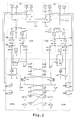
- Fig. 2 shows a block diagram of the monitoring circuits LCI1 and LCI2 and the switching unit U, which is essentially formed by the life cycle relays U1, U2 and the working relays.
- the relays LC1 and LC2 on the board LCI1 correspond to the relay D1 of the embodiment according to FIG. 1 and the relays LC1 and LC2 on the board LCI2 correspond to the relay D2 of the embodiment according to FIG. 1.
- relay U on the board LCR1, or the relay U on the board LCR2 corresponds to the relay U1 or U2 according to FIG. 1.
- the contacts KU12 or KU22 according to FIG. 1 correspond to the contacts KUH on the board LCR 1 or, LCR2.
- all outputs K are no longer switched individually, as is the case in the embodiment according to FIG. 1, but rather the supply of the output relays and the supply of the output contacts are switched to find the way out with fewer contacts.
- the switchover unit U furthermore has buttons T1 which are provided for a manual switchover of the command output KO from one computer to another. Furthermore, keys T2 are also provided, with which a self-test of the monitoring circuits LCI1 or LCI2 can be triggered.
- the monitoring circuits LCI1, LCI2 have two flashing-duration detection circuits 10 and relays LC1, LC2 and LT1 and LT2 connected in parallel, the relays LC1 and LC2 being connected in parallel and connected to the output 2 of the respectively assigned computer R1, R2. Furthermore, each circuit LCI1 is provided with a self-test circuit 11.
- each of the two computers sets a continuous signal that can be tapped from output 2. This pulls the relays LC1 and LC2 of the respective circuits LC1, LC2. Furthermore, the two computers R1, R2 set the life cycle as soon as they start executing the program, but the life cycles of the two computers are set with a time delay.
- the flashing duration detection circuits 10 of the circuits LCI1, LCI2 recognize the life cycle signal and emit a signal to the relays LT1, LT2, so that they attract. Via the contacts KLT1, KLT2 of these relays, the relays LCS and LC can now pick up, as a result of which the life cycle relay, which is assigned to the computer R1, R2 which first sets the life cycle, then picks up.
- the relay UH of a circuit LCR1 or LCR2 picks up, the relay UH of the other circuit, which was previously energized, is held via the contacts KLS and KUH of the relays UH and LS arranged in both circuits LCR1, LCR2. If the corresponding relay UH, e.g. If the relay UH of the circuit LCR2 does not attract, the attracted relay UH, e.g. the relay UH of the circuit LCR1 after a certain time, e.g. 300 msec through the LCS relay of the LCR1 circuit. The drop-out delay caused by the protective diode above the respective relay UH is sufficient to ensure a safe overlap of the command outputs.
- Each circuit board LCI1, LCI2 contains a self-test device 11 for the flashing-duration detection circuit 10.
- This self-test device 11 applies a continuous voltage to the input of the flashing-duration detection circuit 10 and monitors whether this is recognized by the flashing-duration detection circuit 10.
- the proper sequence of the self-test is indicated by LEDs.
- a self-test is started by pressing the T2 button on the LGR1 or LCR2 board. However, a self-test is only permitted for the computer working as a stand-by computer, which is guaranteed by the KU contact.
Abstract
Description
Die Erfindung bezieht sich auf ein Rechnersystem mit zwei parallel arbeitenden Rechnern, von denen einer als Hauptrechner und der andere als Stand-by-Rechner auf einen gemeinsamen Befehlsausgang arbeiten.The invention relates to a computer system with two computers working in parallel, one of which works as a main computer and the other as a stand-by computer on a common command output.
Solche Rechnersysteme werden für Zwecke eingesetzt, bei denen ein sehr hohes Maß an Zuverlässigkeit gefordert ist. Bei bekannten Systemen dieser Art werden die Ausgänge der beiden Rechner miteinander verglichen und diese nur dann weiter verarbeitet, wenn die Ausgänge idente Signale liefern. ein solches System ist nur dann verwendbar, wenn die Signalausgabe unterbrochen werden kann und es nur darauf ankommt allenfalls unrichtige Ergebnisse von Programmabläufen auszuschließen. Für Anwendungszwecke, bei denen eine ständige Signalausgabe des Rechnersystems erforderlich ist, wie z.B. bei Steuerungen von Anlagen und Einrichtungen, sind solche Systeme nicht geeignet, da es bei einem Fehler in einem Rechner zu einer Unterbrechung der Signalausgabe kommt.Such computer systems are used for purposes where a very high degree of reliability is required. In known systems of this type, the outputs of the two computers are compared with one another and these are only processed further if the outputs deliver identical signals. Such a system can only be used if the signal output can be interrupted and it is only important to rule out incorrect results from program sequences. For applications in which a constant signal output from the computer system is required, e.g. Such systems are not suitable for the control of plants and equipment, since an error in a computer interrupts the signal output.
Weiters sind Rechnersysteme mit drei Rechnern bekannt, deren Ausgangssignale miteinander verglichen werden und im Falle von Unterschieden zwischen den einzelnen Ausgangssignalen jene beiden Rechner zum Befehlsausgang durchgeschaltet werden, die idente Signale liefern.Furthermore, computer systems with three computers are known, the output signals of which are compared with one another and, in the event of differences between the individual output signals, those two computers which provide identical signals are switched through to the command output.
Der Nachteil eines solchen Systems, bei dem mit sehr großer Sicherheit eine ständige richtige Signalausgabe gewährleistet ist, liegt in dem erforderlichen hohen AufwandThe disadvantage of such a system, in which a constant correct signal output is guaranteed with great certainty, lies in the high effort required
Ziel der Erfindung ist es, diese Nachteile zu vermeiden und ein Rechnersystem der eingangs erwähnten Art vorzuschlagen, bei dem mit geringem Aufwand eine ständige kontrollierte Signalausgabe an dem gemeinsamen Befehlsausgang gewährleistet ist.The aim of the invention is to avoid these disadvantages and to propose a computer system of the type mentioned in the introduction, in which a constant controlled signal output is ensured at the common command output with little effort.
Erfindungsgemäß wird dies dadurch erreicht, daß jeder Rechner eine den Ablauf des Programms überwachende Schaltung aufweist, die bei ordnungsgemäßem Programmablauf ein Lebenstakt-Signal niedriger Frequenz abgibt und dieses bei einer Endlosschleife oder einem Halt des Programms absetzt und eine weitere Schaltung aufweist, die während des Laufes des Rechners ein Dauersignal abgibt, das ein Arbeits-Relais steuert, und der Ausgang der das Lebenstakt-Signal liefernden Schaltung eines jeden Rechners mit einer Überwachungsschaltung verbunden ist, die ein Lebenstakt-Relais steuert, dem eine mit Kontakten des Arbeits- und des Lebenstakt-Relais des jeweils anderen Rechners gebildete Verriegelungsschaltung zugeordnet ist und dessen einer Kontakt dem Ausgang des zugeordneten Rechners und dem gemeinsamen Befehlsausgang geschaltet ist, wobei die mit dem Befehlsausgang verbundenen Anschlüsse dieser Kontakte der Lebensdauer-Relais miteinander verbunden sind.According to the invention this is achieved in that each computer has a circuit which monitors the execution of the program, which, when the program is running properly, emits a low-frequency life cycle signal and emits it when the program is in an endless loop or stops and has a further circuit which is active during the run of the computer emits a continuous signal, which controls a work relay, and the output of the circuit providing the life cycle signal of each computer is connected to a monitoring circuit which controls a life cycle relay, to which a locking circuit formed with contacts of the work and life cycle relays of the other computer is assigned and whose one contact is connected to the output of the assigned computer and the common command output is, the terminals of these contacts of the life relays connected to the command output being interconnected.
Auf diese Weise ist gewährleistet, daß bei einem Fehler im Programmablauf des als Hauptrechner arbeitenden Rechners dieser vom Befehlsausgang getrennt und der bisher als Stand-by-Rechner arbeitende Rechner mit dem Befehlsausgang verbunden wird. Auf diese Weise ist mit relativ geringem Aufwand eine ständige Signalausgabe am Befehlsausgang des Systems gewährleistet, auch wenn es zu einer Störung im Programmablauf des als Hauptrechner arbeitenden Rechners kommt. In diesemm Falle erfolgt die Signalausgabe unterbrechungslos vom bisher als Stand-by-Rechner arbeitenden Rechner. Diese unterbrechungslose Umschaltung ist, wenn das Programm des als Hauptrechner arbeitenden Rechners in eine Endlosschleife läuft durch die Überwachung des Lebenstaktes gewährleistet. Falls dagegen des Programm des als Hauptrechner arbeitenden Rechners in ein Halt läuft und stehen bleibt, so führt dies zu einer Unterbrechung des Dauersignals, wodurch das von diesem gesteuerte Arbeits-Relais abfällt und eine Umschaltung des Befehlsausganges auf den bisherigen Stand-by-Rechner auslöst.In this way it is ensured that in the event of an error in the program sequence of the computer operating as the main computer, the latter is separated from the command output and the computer previously operating as a stand-by computer is connected to the command output. In this way, a constant signal output at the command output of the system is ensured with relatively little effort, even if there is a malfunction in the program flow of the computer working as the main computer. In this case, the signal is output without interruption from the computer previously operating as a stand-by computer. This uninterrupted switchover is ensured when the program of the computer working as the main computer runs in an endless loop by monitoring the life cycle. If, on the other hand, the program of the computer working as the main computer stops and stops, this leads to an interruption of the continuous signal, as a result of which the work relay controlled by it drops out and triggers a switchover of the command output to the previous standby computer.
Nach einem weiteren Merkmal der Erfindung kann vorgesehen sein, daß eine Schaltung zum zeitversetzten Start des Lebenstakt-Signales der beiden Rechner beim Start derselben vorgesehen ist.According to a further feature of the invention it can be provided that a circuit is provided for the delayed start of the life cycle signal of the two computers when the same is started.
Dadurch kann auf einfache Weise festgelegt werden, welcher der beiden Rechner beim Hochfahren derselben zum Befehlsausgang durchgeschaltet wird.This makes it easy to determine which of the two computers is switched through to the command output when the computer is started up.
Nach einem weiteren Merkmal der Erfindung kann vorgesehen sein, daß die Lebensdauer-Relais als bistabile Relais ausgebildet sind und die Überwachungsschaltungen, wie auch Lebensdauer-Relais und Arbeits-Relais eines jeden Rechners auf separaten Leiterplatten angeordnet sind, wobei auf letzteren auch eine Einrichtung zum händischen Umschalten des Befehlsausganges auf einen bestimmten Rechner angeordnet sind.According to a further feature of the invention it can be provided that the service life relays are designed as bistable relays and the monitoring circuits, as well as service life relays and work relays of each computer are arranged on separate printed circuit boards, the latter also having a device for manual operation Switching the command output are arranged on a specific computer.
Auf diese Weise ist es möglich im Falle eines Fehlers der Überwachungsschaltung oder der zur Umschaltung des Befehlsausganges von einem Rechner zum anderen erforderlichen Relais nach einem entsprechenden händischen Umschalten die entsprechende Leiterplatte auszutauschen.In this way it is possible in the event of a fault in the monitoring circuit or in the relays required to switch the command output from one computer to another after a corresponding manual switchover, to replace the corresponding printed circuit board.
Die Erfindung wird nun anhand der Zeichnung näher erläutert. Dabei zeigen:
- Fig. 1 schematisch ein erfindungsgemäßes Rechnersystem, und
- Fig. 2 schematisch ein Ausführungsbeispiel für die zur automatischen Umschaltung des Befehlsausganges von einem Rechner zum anderen vorgesehenen Einrichtung.
- Fig. 1 shows schematically an inventive computer system, and
- Fig. 2 shows schematically an embodiment for the device provided for automatically switching the command output from one computer to another.
Wie aus der Fig. 1 ersichtlich ist, sind die Eingänge I₁, bis In der beiden Rechner R1 und R2 parallel geschaltet. Dabei arbeitet der Rechner R1 als Hauptrechner und der Rechner R2 als Stand-by-Rechner, wobei aber beide Rechner R1, R2 die an den Eingängen I₁ bis In einlangenden Informationen nach identen Programmen gleichzeitig verarbeiten und die verarbeiteten Signale an den Ausgängen K beider Rechner R1, R2 zur gleichen Zeit abgreifbar sind.As can be seen from Fig. 1, the inputs I₁ to I n of the two computers R1 and R2 are connected in parallel. The computer R1 works as the main computer and the computer R2 as a stand-by computer, but both computers R1, R2 process the information arriving at the inputs I 1 to I n simultaneously according to identical programs and the processed signals at the outputs K of both computers R1, R2 can be tapped at the same time.
Die Rechner R1 und R2 weisen je einen Software-Modul 20 auf, die den Ablauf des Programms überwachen und bei einem ordnungsgemäßen Programmablauf ein Lebenstakt-Signal niedriger Frequenz erzeugen, das am Ausgang 1 eines jeden Rechners R1, R2 abgreifbar ist. Die Abgabe dieses Signales unterbleibt, sobald das Programm in eine Endlosschleife oder in einen Halt läuft.The computers R1 and R2 each have a
Weiters wird durch einen Software-Modul 30 ein Dauersignal erzeugt, das bei einem Halt des Rechners automatisch rückgesetzt wird, welches Dauersignal an den Ausgängen 2 eines jeden Rechners R1, R2 abgreifbar ist.Furthermore, a permanent signal is generated by a
An den Ausgang 1 eines jeden Rechners R1, R2 ist eine Überwachungsschaltung LCI1, bzw LCI2 angeschlossen, die ein Lebenstakt-Relais U1, bzw. U2 steuert. Dabei wird ein Anziehen des entsprechenden Relais U1, U2 ermöglicht, solange die Überwachungsschaltung LCI1, LCI2 ein einem anliegenden Lebenstakt-Signal entsprechendens Signal liefert.A monitoring circuit LCI1 or LCI2 is connected to the
Weiters steuert der Ausgang 2 eines jeden Rechners R1, R2 ein Arbeits-Relais D1, D2.Furthermore, the
Die Lebenstakt-Relais U1, U2 sind mit einer Reihenschaltung eines Arbeitskontaktes des dem selben Rechner R1, R2 zugeordneten Arbeitsrelais D1, D2 und eines Ruhekontaktes des dem anderen Rechner zugeordneten Lebenstakt-Relais U1, U2, gegeneinander verriegelt.The life cycle relays U1, U2 are connected in series with a normally open contact of the same computer R1, R2 associated working relay D1, D2 and a normally closed contact of the life cycle relay U1, U2 assigned to the other computer interlocked.
Dabei ist durch die Software der beiden Rechnern R1, R2 sichergestellt, daß die Lebenstakte der beiden Rechner R1, R2 gegeneinander um eine geringe Zeitspanne zeitversetzt starten. Dadurch wird sichergestellt, daß bei Hochfahren der beiden Rechner R1, R2 eines der beiden Lebenstakt-Relais U1, U2 zuerst anzieht und damit ein Anzeihen des Lebenstakt-Relais U1, U2 des anderen Rechners über seinen Ruhekontakt verhindert.The software of the two computers R1, R2 ensures that the life cycles of the two computers R1, R2 start against each other with a short time delay. This ensures that when the two computers R1, R2 start up, one of the two life cycle relays U1, U2 picks up first and thus prevents the life cycle relay U1, U2 from being shown by the other computer via its normally closed contact.
Dabei schaltet ein Arbeitskontakt KU12 des Lebenstakt-Relais U1, bzw. eine Arbeitskontakt KU22 des Lebenstakt-Relais U2 den Ausgang K des jeweils zugeordneten Rechners R1, R2 zum Befehlsausgang KO durch, wobei die beiden Arbeitskontakte KU12 und KU22 miteinander verbunden sind.A work contact KU12 of the life cycle relay U1, or a work contact KU22 of the life cycle relay U2, switches the output K of the respectively assigned computer R1, R2 to the command output KO, the two work contacts KU12 and KU22 being connected to one another.
Dadurch ist sichergestellt, daß sobald das Programm des als Hauptrechner arbeitenden Rechners R1, R2, dessen Ausgang K zum Befehlsausgang KO durchgeschaltet ist, in eine Endlosschleife läuft, wodurch kein Lebenstakt-Signal mehr zur entsprechenden Überwachungsschaltung, z.B. LCI1 gelangt und daher das entsprechende Lebenstakt-Relais, z.B. U1 umschaltet. Dadurch zieht das jeweils andere Lebensdauer-Relais, z.B. U2 an, wodurch der Arbeitskontakt KU12 öffnet und der Arbeitskontakt KU22 schließt und daher der Ausgang K des anderen Rechners, z.B. R2, zum Befehlsausgang KO durchgeschaltet ist.This ensures that as soon as the program of the computer R1, R2 working as the main computer, whose output K is connected to the command output KO, runs in an endless loop, as a result of which no more life cycle signal to the corresponding monitoring circuit, e.g. LCI1 arrives and therefore the corresponding life cycle relay, e.g. U1 switches. This pulls the other lifetime relay, e.g. U2 on, whereby the normally open contact KU12 opens and the normally open contact KU22 closes and therefore the output K of the other computer, e.g. R2, is switched through to the command output KO.
Fig. 2 zeigt ein Blockschaltbild der Überwachungsschaltungen LCI1 und LCI2 und der Umschalteinheit U, die im wesentlichen durch die Lebenstakt-Relais U1, U2 und die Arbeitsrelais gebildet ist. Dabei entsprechen die Relais LC1 und LC2 auf der Platine LCI1 dem Relais D1 der Ausführungsform nach der Fig. 1 und die Relais LC1 und LC2 auf der Platine LCI2 dem Relais D2 der Ausführungsform nach der Fig. 1.Fig. 2 shows a block diagram of the monitoring circuits LCI1 and LCI2 and the switching unit U, which is essentially formed by the life cycle relays U1, U2 and the working relays. The relays LC1 and LC2 on the board LCI1 correspond to the relay D1 of the embodiment according to FIG. 1 and the relays LC1 and LC2 on the board LCI2 correspond to the relay D2 of the embodiment according to FIG. 1.
Weiters entspricht das Relais U auf der Platine LCR1, bzw. das Relais U auf der Platine LCR2 dem Relais U1 bzw. U2 nach der Fig. 1.Furthermore, the relay U on the board LCR1, or the relay U on the board LCR2 corresponds to the relay U1 or U2 according to FIG. 1.
Weiters entsprechen die Kontakte KU12 bzw. KU22 nach der Fig. 1 den Kontakten KUH auf der Platine LCR 1 bzw, LCR2. Allerdings werden bei der Ausführungsform nach der Fig. 2 nicht mehr alle Ausgänge K einzeln umgeschaltet, wie dies bei der Ausführungsform nach der Fig. 1 der Fall ist, sondern es wird die Anspeisung der Ausgangsrelais und die Anspeisung der Ausgangskontakte umgeschlatet um mit weniger Kontakten das Auslangen zu finden.Furthermore, the contacts KU12 or KU22 according to FIG. 1 correspond to the contacts KUH on the
Wie aus der Fig. 2 zu ersehen ist, weist die Umschalteinheit U weiters Tasten T1, die für eine manuelle Umschaltung des Befehlsausganges KO von einem Rechner zum anderen vorgesehen sind. Weiters sind noch Tasten T2 vorgesehen, mit denen ein Selbsttest der Überwachungsschaltungen LCI1, bzw. LCI2 ausgelöst werden kann.As can be seen from FIG. 2, the switchover unit U furthermore has buttons T1 which are provided for a manual switchover of the command output KO from one computer to another. Furthermore, keys T2 are also provided, with which a self-test of the monitoring circuits LCI1 or LCI2 can be triggered.
Die Überwachungsschaltungen LCI1, LCI2 weisen zwei parallel geschaltete Blink-Dauer-Erkennungsschaltungen 10 und Relais LC1, LC2 und LT1 sowie LT2 auf, wobei die Relais LC1, und LC2 parallel geschaltet und mit dem Ausgang 2 des jeweils zugeordneten Rechners R1, R2 verbunden sind. Weiters ist jede Schaltung LCI1 mit einer Selbsttestschaltung 11 versehen.The monitoring circuits LCI1, LCI2 have two flashing-
Beim Hochlaufen der beiden Rechner R1, R2 setzt jeder der beiden Rechner ein Dauersignal, das vom Ausgang 2 abgreifbar ist. Dadurch ziehen die Relais LC1 und LC2 der jeweiligen Schaltungen LC1, LC2 an. Weiters setzen die beiden Rechner R1, R2 den Lebenstakt, sobald sie mit dem Abarbeiten des Programms beginnen, wobei aber die Lebenstakte der beiden Rechner zeitversetzt gesetzt werden.When the two computers R1, R2 start up, each of the two computers sets a continuous signal that can be tapped from
Die Blink-Dauer-Erkennungsschaltungen 10 der Schaltungen LCI1, LCI2 erkennen das Lebenstakt-Signal und geben ein Signal an die Relais LT1, LT2 ab, sodaß diese anziehen. Über die Kontakte KLT1, KLT2 dieser Relais können nun auch die Relais LCS und LC anziehen, wodurch in weiterer Folge das Lebenstakt-Relais anzieht, das jenem Rechner R1, R2 zugeordnet ist, der zuerst den Lebenstakt setzt.The flashing
Bei einem Ausfall des mit dem Befehlsausgang KO verbundenen Rechners R1, R2 setzt dieser das Dauersignal an seinem Ausgang 2 retour, wodurch die entsprechenden Relais LC1 und LC2 abfallen. Dadurch fallen auch dem selben Rechner zugeordnete Relais LT1 und LT2 und weiters das zugeordnete Relais LC ab.In the event of a failure of the computer R1, R2 connected to the command output KO, the latter sets the continuous signal back at its
Über die Kontakte KLC der in beiden Schaltungen LCR1, LCR2-angeordneten Relais LC werden die beiden Lebenstakt-Relais U1, U2 umgeschaltet und damit, wie bereits erläutert, der Befehlsausgang KO mit dem jeweils anderen Rechner R1, R2 verbunden.Via the contacts KLC of the relays LC arranged in both circuits LCR1, LCR2, the two life cycle relays U1, U2 are switched over and, as already explained, the command output KO is connected to the respective other computer R1, R2.
Dabei wird bis zum Anzug des Relais UH einer Schaltung LCR1, bzw. LCR2 das Relais UH der anderen Schaltung, das bisher angezogen war, über die Kontakte KLS und KUH der in beiden Schaltungen LCR1, LCR2 angeordneten Relais UH und LS gehalten. Sollte das entsprechende Relais UH, z.B. das Relais UH der Schaltung LCR2 nicht anziehen, so wird das angezogene Relais UH, z.B. das Relais UH der Schaltung LCR1 nach einer bestimmten Zeit, z.B. 300msec durch das Relais LCS der Schaltung LCR1 abgeworfen. Die Abfallverzögerung, die durch die Schutzdiode über dem jeweiligen Relais UH bedingt ist, genügt, um eine sichere Überschneidung der Befehlsausgaben sicherzustellen.In this case, until the relay UH of a circuit LCR1 or LCR2 picks up, the relay UH of the other circuit, which was previously energized, is held via the contacts KLS and KUH of the relays UH and LS arranged in both circuits LCR1, LCR2. If the corresponding relay UH, e.g. If the relay UH of the circuit LCR2 does not attract, the attracted relay UH, e.g. the relay UH of the circuit LCR1 after a certain time, e.g. 300 msec through the LCS relay of the LCR1 circuit. The drop-out delay caused by the protective diode above the respective relay UH is sufficient to ensure a safe overlap of the command outputs.
Bei einem Ausfall des Lebenstaktes des als Hauptrechner arbeitenden Rechners R1, R2 wird dieser Ausfall durch die entsprechnden Blink-Dauer-Erkennungsschaltungen 10 erkannt und diese bewirken einen Abfall der entsprechenden Relais LT1 und LT2, wodurch es zu einem Umschalten der Lebenstakt-Relais U1, U2 kommtIf the life cycle of the computer R1, R2 working as the main computer fails, this failure is recognized by the corresponding flashing
Eine händische Umschaltung ist durch Drücken der Umschalttaste T1 auf der jeweiligen Platine LCR1, LCR2 möglich. Dabei werden über die Kontakte KLC die beiden Lebenstakt-Relais U1, U2 umgeschaltet und damit, wie bereits erwähnt, der Befehlsausgang KO mit dem der jeweiligen Platine LCR1, LCR2 zugeordneten Rechner R1, R2 verbunden.Manual switchover is possible by pressing the switchover key T1 on the respective circuit board LCR1, LCR2. The two life cycle relays U1, U2 are switched over via the contacts KLC and, as already mentioned, the command output KO is connected to the computer R1, R2 assigned to the respective circuit board LCR1, LCR2.
Jede Platine LCI1, LCI2 enthält eine Selbsttesteinrichtung 11 für die Blink-Dauer-Erkennungsschaltung 10. Diese Selbsttesteinrichtung 11 legt eine Dauerspannung an den Eingang der Blink-Dauer-Erkennungsschaltung 10 und überwacht ob dies von der Blink-Dauer-Erkennungsschaltung 10 erkannt wird. Der ordnungsgemäße Ablauf des Selbsttestes wird durch Leuchtdioden angezeigt. Ein Selbsttest wird durch Drücken der Taste T2 an der Platine LGR1, bzw. LCR2 gestartet. Ein Selbstest ist jedoch nur beim als Stand-by-Rechner arbeitenden Rechner zulässig, was durch den Kontakt KU gewährleistet wird.Each circuit board LCI1, LCI2 contains a self-
Claims (3)
Applications Claiming Priority (2)
| Application Number | Priority Date | Filing Date | Title |
|---|---|---|---|
| AT218591A AT398645B (en) | 1991-11-04 | 1991-11-04 | COMPUTER SYSTEM |
| AT2185/91 | 1991-11-04 |
Publications (2)
| Publication Number | Publication Date |
|---|---|
| EP0541508A2 true EP0541508A2 (en) | 1993-05-12 |
| EP0541508A3 EP0541508A3 (en) | 1993-10-20 |
Family
ID=3529538
Family Applications (1)
| Application Number | Title | Priority Date | Filing Date |
|---|---|---|---|
| EP19920890234 Withdrawn EP0541508A3 (en) | 1991-11-04 | 1992-11-04 | Computer system |
Country Status (4)
| Country | Link |
|---|---|
| EP (1) | EP0541508A3 (en) |
| AT (1) | AT398645B (en) |
| HU (1) | HUT68436A (en) |
| PL (1) | PL296461A1 (en) |
Cited By (1)
| Publication number | Priority date | Publication date | Assignee | Title |
|---|---|---|---|---|
| EP0732654A1 (en) * | 1995-03-16 | 1996-09-18 | ABBPATENT GmbH | Method for fault-tolerant communication under real-time conditions |
Citations (4)
| Publication number | Priority date | Publication date | Assignee | Title |
|---|---|---|---|---|
| US3303474A (en) * | 1963-01-17 | 1967-02-07 | Rca Corp | Duplexing system for controlling online and standby conditions of two computers |
| US3833890A (en) * | 1972-03-17 | 1974-09-03 | Int Standard Electric Corp | Safety device |
| GB2187909A (en) * | 1986-03-13 | 1987-09-16 | Lake Electronic Tech | Power on reset & watchdog circuit |
| US5022076A (en) * | 1988-12-09 | 1991-06-04 | The Exchange System Limited Partnership | Redundant encryption processor arrangement for use in an electronic fund transfer network |
Family Cites Families (4)
| Publication number | Priority date | Publication date | Assignee | Title |
|---|---|---|---|---|
| DE2729362C2 (en) * | 1977-06-29 | 1982-07-08 | Siemens AG, 1000 Berlin und 8000 München | Digital data processing arrangement, especially for railway safety technology, with switchgear that processes the same information in two channels |
| GB2217487B (en) * | 1988-04-13 | 1992-09-23 | Yokogawa Electric Corp | Dual computer system |
| DE3919183A1 (en) * | 1989-06-12 | 1990-12-13 | Siemens Ag | CIRCUIT FOR MONITORING THE VOLTAGE OF A SELECTED DC POWER SUPPLY IN A REDUNDANT POWER SUPPLY SYSTEM |
| DE3938501A1 (en) * | 1989-11-20 | 1991-05-23 | Siemens Ag | METHOD FOR OPERATING A MULTI-CHANNEL FAILSAFE COMPUTER SYSTEM AND DEVICE FOR IMPLEMENTING THE METHOD |
-
1991
- 1991-11-04 AT AT218591A patent/AT398645B/en not_active IP Right Cessation
-
1992
- 1992-10-30 HU HU9203410A patent/HUT68436A/en unknown
- 1992-11-03 PL PL29646192A patent/PL296461A1/en unknown
- 1992-11-04 EP EP19920890234 patent/EP0541508A3/en not_active Withdrawn
Patent Citations (4)
| Publication number | Priority date | Publication date | Assignee | Title |
|---|---|---|---|---|
| US3303474A (en) * | 1963-01-17 | 1967-02-07 | Rca Corp | Duplexing system for controlling online and standby conditions of two computers |
| US3833890A (en) * | 1972-03-17 | 1974-09-03 | Int Standard Electric Corp | Safety device |
| GB2187909A (en) * | 1986-03-13 | 1987-09-16 | Lake Electronic Tech | Power on reset & watchdog circuit |
| US5022076A (en) * | 1988-12-09 | 1991-06-04 | The Exchange System Limited Partnership | Redundant encryption processor arrangement for use in an electronic fund transfer network |
Cited By (2)
| Publication number | Priority date | Publication date | Assignee | Title |
|---|---|---|---|---|
| EP0732654A1 (en) * | 1995-03-16 | 1996-09-18 | ABBPATENT GmbH | Method for fault-tolerant communication under real-time conditions |
| US5784547A (en) * | 1995-03-16 | 1998-07-21 | Abb Patent Gmbh | Method for fault-tolerant communication under strictly real-time conditions |
Also Published As
| Publication number | Publication date |
|---|---|
| EP0541508A3 (en) | 1993-10-20 |
| AT398645B (en) | 1995-01-25 |
| PL296461A1 (en) | 1993-06-14 |
| HUT68436A (en) | 1995-06-28 |
| HU9203410D0 (en) | 1993-03-01 |
| ATA218591A (en) | 1994-05-15 |
Similar Documents
| Publication | Publication Date | Title |
|---|---|---|
| EP0535205B1 (en) | Device for monitoring a control unit | |
| EP1869687B1 (en) | Safety switch for the safe disconnection of an electric consumer | |
| DE2711416C2 (en) | Arrangement for displaying the switching status of the switches | |
| DE2059797B1 (en) | Clock supply system | |
| DE2651314B1 (en) | Safety output circuit for a data processing system which emits binary signals | |
| EP0541508A2 (en) | Computer system | |
| DE3137450C2 (en) | Safety output circuit for a data processing system | |
| EP0471935B1 (en) | Circuit for supervising a matrix of bistable points | |
| DE2621397A1 (en) | SAFETY CIRCUIT, IN PARTICULAR FOR LIFT SYSTEMS | |
| EP2645511A1 (en) | Emergency deactivation monitoring | |
| DE4319750C2 (en) | Method and device for function monitoring of switching devices of a bridge circuit and their use | |
| DE19913933A1 (en) | Circuit for switching on user load e.g safety release equipment | |
| DE1513297B2 (en) | CIRCUIT ARRANGEMENT FOR DETECTION OF L OR O SIGNAL ERRORS FOR AT LEAST ONE TWO-CHANNEL CONTROL CIRCUIT | |
| DE3832800C2 (en) | ||
| EP0178402B1 (en) | Monitoring circuit | |
| DE1961972C3 (en) | Circuit arrangement for controlling electrical switching devices using keys | |
| DE2002353A1 (en) | Method for the detection of false signals | |
| AT209950B (en) | Signal box for railway safety devices | |
| DE3022058C2 (en) | Device for the safe control of a switching element in terms of signaling | |
| DE950128C (en) | Monitoring device for step switches in railroad safety systems | |
| DE1270667B (en) | Circuit arrangement for dynamic monitoring of the operational safety of individual or linked contactless control modules | |
| DE1605428C (en) | Circuit arrangement for testing relay-monitored signal circuits, in particular light signal circuits in railway safety systems, for external voltage | |
| DE1118274B (en) | Method and circuit arrangement for automatically determining the location of errors which occur in a message processing system, in particular in a telephone exchange system | |
| DE1690279A1 (en) | Circuit arrangement for the transmission of information between a command station and several substations | |
| DE4112625A1 (en) | Testing function of switching device activated by magnetic field, e.g. in machine tool - applying compensating magnetic field and checking that switch is deactivated |
Legal Events
| Date | Code | Title | Description |
|---|---|---|---|
| PUAI | Public reference made under article 153(3) epc to a published international application that has entered the european phase |
Free format text: ORIGINAL CODE: 0009012 |
|
| AK | Designated contracting states |
Kind code of ref document: A2 Designated state(s): BE CH DE ES FR GB IT LI NL PT SE |
|
| PUAL | Search report despatched |
Free format text: ORIGINAL CODE: 0009013 |
|
| AK | Designated contracting states |
Kind code of ref document: A3 Designated state(s): BE CH DE ES FR GB IT LI NL PT SE |
|
| STAA | Information on the status of an ep patent application or granted ep patent |
Free format text: STATUS: THE APPLICATION IS DEEMED TO BE WITHDRAWN |
|
| 18D | Application deemed to be withdrawn |
Effective date: 19940421 |