EP0542673A1 - Process for automatically depositing an adhesive shaped strip along the edge of a glass sheet and device for application of the process - Google Patents
Process for automatically depositing an adhesive shaped strip along the edge of a glass sheet and device for application of the process Download PDFInfo
- Publication number
- EP0542673A1 EP0542673A1 EP92810790A EP92810790A EP0542673A1 EP 0542673 A1 EP0542673 A1 EP 0542673A1 EP 92810790 A EP92810790 A EP 92810790A EP 92810790 A EP92810790 A EP 92810790A EP 0542673 A1 EP0542673 A1 EP 0542673A1
- Authority
- EP
- European Patent Office
- Prior art keywords
- pressing device
- pressing
- profile
- liquid
- shaped strip
- Prior art date
- Legal status (The legal status is an assumption and is not a legal conclusion. Google has not performed a legal analysis and makes no representation as to the accuracy of the status listed.)
- Withdrawn
Links
Images
Classifications
-
- C—CHEMISTRY; METALLURGY
- C03—GLASS; MINERAL OR SLAG WOOL
- C03C—CHEMICAL COMPOSITION OF GLASSES, GLAZES OR VITREOUS ENAMELS; SURFACE TREATMENT OF GLASS; SURFACE TREATMENT OF FIBRES OR FILAMENTS MADE FROM GLASS, MINERALS OR SLAGS; JOINING GLASS TO GLASS OR OTHER MATERIALS
- C03C27/00—Joining pieces of glass to pieces of other inorganic material; Joining glass to glass other than by fusing
- C03C27/04—Joining glass to metal by means of an interlayer
- C03C27/048—Joining glass to metal by means of an interlayer consisting of an adhesive specially adapted for that purpose
-
- B—PERFORMING OPERATIONS; TRANSPORTING
- B29—WORKING OF PLASTICS; WORKING OF SUBSTANCES IN A PLASTIC STATE IN GENERAL
- B29C—SHAPING OR JOINING OF PLASTICS; SHAPING OF MATERIAL IN A PLASTIC STATE, NOT OTHERWISE PROVIDED FOR; AFTER-TREATMENT OF THE SHAPED PRODUCTS, e.g. REPAIRING
- B29C43/00—Compression moulding, i.e. applying external pressure to flow the moulding material; Apparatus therefor
- B29C43/02—Compression moulding, i.e. applying external pressure to flow the moulding material; Apparatus therefor of articles of definite length, i.e. discrete articles
- B29C43/18—Compression moulding, i.e. applying external pressure to flow the moulding material; Apparatus therefor of articles of definite length, i.e. discrete articles incorporating preformed parts or layers, e.g. compression moulding around inserts or for coating articles
-
- B—PERFORMING OPERATIONS; TRANSPORTING
- B29—WORKING OF PLASTICS; WORKING OF SUBSTANCES IN A PLASTIC STATE IN GENERAL
- B29C—SHAPING OR JOINING OF PLASTICS; SHAPING OF MATERIAL IN A PLASTIC STATE, NOT OTHERWISE PROVIDED FOR; AFTER-TREATMENT OF THE SHAPED PRODUCTS, e.g. REPAIRING
- B29C43/00—Compression moulding, i.e. applying external pressure to flow the moulding material; Apparatus therefor
- B29C43/32—Component parts, details or accessories; Auxiliary operations
- B29C43/52—Heating or cooling
-
- B—PERFORMING OPERATIONS; TRANSPORTING
- B29—WORKING OF PLASTICS; WORKING OF SUBSTANCES IN A PLASTIC STATE IN GENERAL
- B29C—SHAPING OR JOINING OF PLASTICS; SHAPING OF MATERIAL IN A PLASTIC STATE, NOT OTHERWISE PROVIDED FOR; AFTER-TREATMENT OF THE SHAPED PRODUCTS, e.g. REPAIRING
- B29C70/00—Shaping composites, i.e. plastics material comprising reinforcements, fillers or preformed parts, e.g. inserts
- B29C70/68—Shaping composites, i.e. plastics material comprising reinforcements, fillers or preformed parts, e.g. inserts by incorporating or moulding on preformed parts, e.g. inserts or layers, e.g. foam blocks
- B29C70/74—Moulding material on a relatively small portion of the preformed part, e.g. outsert moulding
- B29C70/76—Moulding on edges or extremities of the preformed part
- B29C70/763—Moulding on edges or extremities of the preformed part the edges being disposed in a substantial flat plane
-
- B—PERFORMING OPERATIONS; TRANSPORTING
- B29—WORKING OF PLASTICS; WORKING OF SUBSTANCES IN A PLASTIC STATE IN GENERAL
- B29C—SHAPING OR JOINING OF PLASTICS; SHAPING OF MATERIAL IN A PLASTIC STATE, NOT OTHERWISE PROVIDED FOR; AFTER-TREATMENT OF THE SHAPED PRODUCTS, e.g. REPAIRING
- B29C35/00—Heating, cooling or curing, e.g. crosslinking or vulcanising; Apparatus therefor
- B29C35/02—Heating or curing, e.g. crosslinking or vulcanizing during moulding, e.g. in a mould
- B29C2035/0216—Heating or curing, e.g. crosslinking or vulcanizing during moulding, e.g. in a mould using Peltier-effect
-
- B—PERFORMING OPERATIONS; TRANSPORTING
- B29—WORKING OF PLASTICS; WORKING OF SUBSTANCES IN A PLASTIC STATE IN GENERAL
- B29L—INDEXING SCHEME ASSOCIATED WITH SUBCLASS B29C, RELATING TO PARTICULAR ARTICLES
- B29L2031/00—Other particular articles
- B29L2031/26—Sealing devices, e.g. packaging for pistons or pipe joints
-
- B—PERFORMING OPERATIONS; TRANSPORTING
- B29—WORKING OF PLASTICS; WORKING OF SUBSTANCES IN A PLASTIC STATE IN GENERAL
- B29L—INDEXING SCHEME ASSOCIATED WITH SUBCLASS B29C, RELATING TO PARTICULAR ARTICLES
- B29L2031/00—Other particular articles
- B29L2031/30—Vehicles, e.g. ships or aircraft, or body parts thereof
- B29L2031/3055—Cars
Definitions
- the invention relates to the method described in claims 1 to 6 for the mechanical application of an adhesive profile strand along the edge of a glass pane and to the device described in claims 7 to 10 for carrying out this method.
- the deformed profile strand part is separated from the non-deformed profile strand part, in the region of the starting point of the extrusion profile nozzle, mechanically by means of a cut made transversely to the profile. Then the separated deformed initial part is machined from the Glass surface loosened and removed. Then, in the area of the end point of the profile nozzle, it is lifted off the glass surface and the profile strand is mechanically cut to such a length by means of a second cut made parallel to the first that the two ends of the profile strand meet congruently. Finally, the end region of the profile strand is pressed mechanically onto the glass surface, and the two ends of the profile strand are pressed together mechanically.
- the contact pressure can be chosen as high as desired.
- the object of the invention is therefore to eliminate the disadvantages of these methods and to provide a method and a device with which the two ends of the profile strand can be connected to one another in a simple and inexpensive manner.
- This object is achieved according to the invention in that the pressing of the end regions of the profile strand both against one another and against the glass surface is carried out with a pressing device equipped with one or more Peltier elements, the pressing surface being cooled prior to pressing and being solidified Liquid is covered and heated up at the latest during pressing and, as long as there is a liquid film between the pressing device and the profile strand, the pressing device is lifted off the profile strand.
- the pressing device must therefore be lifted off at a point in time when the liquid film has not yet evaporated or has been absorbed by the profile strand.
- the Peltier element was switched to heating mode at the latest during the pressing process.
- the pressing device can also be preheated to a temperature at which the solid phase of the liquid is still present on the surface. In this case the cycle time is shortened.
- the pressing device expediently has a counter profile corresponding to the profile of the profile strand.
- the pressing device can be made in one or more parts, in which case each part is expediently provided with at least one Peltier element.
- An at least three-part design of the pressing device is mandatory if the profile strand has undercuts.
- the pressing device or one of its parts is expediently placed at an oblique angle to the glass surface during pressing and then tilted around an edge parallel to the longitudinal direction of the profile strand.
- the excess material of the profile strand is squeezed off, either to a location outside the pressing device or at one Location in the pressing device itself, for example in a recess provided for this purpose in the pressing device. In the latter case, it must then be removed periodically from the pressing device.
- the pressing device is preferably tilted in the direction of the glass pane, so that the excess material of the profile strand is pressed onto the glass pane.
- the pressing device To form the solid phase of the liquid on the pressing device, it is expediently cooled to a temperature of -20 to -40 ° C.
- the pressing device can be preheated to a temperature at which the solid phase of the liquid is still present on the surface. This temperature control takes place through a corresponding power supply to the Peltier elements.
- Water a water-containing mixture or an anhydrous liquid can be used as the liquid.
- Suitable water-containing mixtures are, for example, water surface-active substances, e.g. soap solutions, or starch solutions, e.g. potato juice, dissolved in it.
- the pressing device can be sprayed with the liquid to form the solid phase or immersed in the liquid.
- the pressing device itself it is also possible to design the pressing device itself to be porous, so that the liquid can be supplied through it. In this case it is essential that no drop formation occurs on the surface of the pressing device.
- Sintered metal or leather can be used as materials.
- the measures mentioned not only ensure a coherent connection of the two profile strand ends, but also a problem-free detachment of the pressing device from the adhesive profile strand.
- the temperature of the warm side of the pressing device should not exceed 20 to 25 ° C, otherwise water or air cooling should be provided.
- the entire arrangement is expediently designed in such a way that that the contact pressure of the pressing device is not exerted via the Peltier element, but only on the profile-side parts of the pressing device. This can be accomplished by allowing the pressure generator to act on the pressing device at a point lying between the Peltier element and the profile.
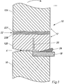
- the embodiment shown in Fig. 1 serves, as mentioned, the processing of a profile strand without undercuts, the profile of which projects beyond the glass pane.
- the pressing device 10 is formed in two parts. It comprises an upper part 12 and a lower part 16 designed as a support.
- a Peltier element 22 comprising the two parts 22A and 22B is arranged between the two parts 12A and 12B of the upper part 12 of the pressing device 10. This is fed with current via connecting wires, not shown.
- the lower part 16 of the pressing device 10 has no such Peltier element, since its contact surface with the profile strand 20 is only small, so that detachment is possible even without special temperature control.
- the two parts 12 and 16 of the pressing device 10 have at their ends a counter profile corresponding to the profile of the profile strand 20 attached to the glass pane 18.
- the glass pane 18 and the profile strand 20 rest on the lower part 16 of the pressing device 10 which is designed as a support. However, this can also be designed such that it only supports the profile strand 20 while the glass pane 18 rests on a separate support.
- the glass pane 18 provided with the profile strand 20 is first placed on the lower part 16 of the pressing device 10. Then the upper part 12 of the pressing device 10 is placed along the edge K, which runs parallel to the longitudinal direction of the profile strand 20, at an oblique angle to the glass surface and then tilted against the glass pane 18 in the position shown. The excess material 28 is pressed onto the glass pane 18.
- the temperature control of the part 12 of the pressing device 10 takes place, as described above, by corresponding current supply to the Peltier element 22.
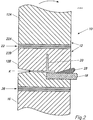
- the improved embodiment shown in FIG. 2 also serves to machine a profile strand without undercuts, the profile of which projects beyond the glass pane. It differs from the embodiment shown in FIG. 1 in that the lower part 16 of the pressing device 10 is provided with a Peltier element 26 in the same way as the upper part 12 of the pressing device 10. The temperature control of the two parts 12 and 16 of the pressing device 10 takes place, as described above, by a corresponding current supply to the two Peltier elements 22 and 26 simultaneously.
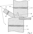
- the embodiment shown in Fig. 3 is used to machine a profile strand with an undercut.
- the pressing device 10 is constructed in three parts. it includes two mutually independent upper parts 12 and 14 and a lower part 16 designed as a support. All three parts 12, 14 and 16 of the pressing device 10 are provided with Peltier elements 22, 24 and 26. The temperature control of all three parts 12, 14 and 16 of the pressing device 10 takes place in the same way as described above by corresponding current supply to the three Peltier elements 22, 24 and 26 simultaneously.
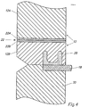
- the embodiment shown in FIG. 4 is used to machine a profile strand without an undercut, the profile of which does not protrude beyond the glass pane.
- the pressing device is formed in one piece and has only an upper part 12.
- the glass pane 18 rests on the support 30.
- the temperature control of the part 12 of the pressing device 10 is carried out in the same way as described above by corresponding current supply to the Peltier element 22.
- the glass pane 18 lies horizontally with the profile strand 20 upwards.
- the processing can just as well be carried out on a vertical, i.e. upright, standing glass pane. In special cases, it can also make sense to carry out processing on a horizontally mounted glass pane with the profile strand pointing downwards.
Abstract
Description
Die Erfindung betrifft das in den Ansprüchen 1 bis 6 umschriebene Verfahren zum maschinellen Aufbringen eines Klebstoff-Profilstranges entlang dem Rand einer Glasscheibe sowie die in den Ansprüchen 7 bis 10 umschriebene Vorrichtung zur Durchführung dieses Verfahrens.The invention relates to the method described in claims 1 to 6 for the mechanical application of an adhesive profile strand along the edge of a glass pane and to the device described in claims 7 to 10 for carrying out this method.
Aus der Veröffentlichung DE-C1-40 22 484 ist ein Verfahren zum maschinellen Aufbringen eines Klebstoff-Profilstranges entlang dem Rand einer Glasscheibe, insbesondere einer Fahrzeugscheibe, bekannt, bei welchem der Klebstoff durch eine mittels eines Roboters entlang dem Glasscheibenrand geführten Extrudier-Profildüse auf die Glasoberfläche angedrückt und der deformierte Anfangs- und Endteil des Profilstranges abgetrennt wird.From publication DE-C1-40 22 484, a method for the mechanical application of an adhesive profile strand along the edge of a glass pane, in particular a vehicle window, is known, in which the adhesive is applied to the extrusion profile nozzle by a robot guided along the edge of the glass pane Pressed on the glass surface and the deformed beginning and end part of the profile strand is separated.
Bei diesem Verfahren erfolgt das Abtrennen des deformierten Profilstrangteiles vom nicht deformierten Profilstrangteil, im Bereich des Startpunktes der Extrudier-Profildüse, maschinell mittels eines quer zum Profil geführten Schnittes. Dann wird der abgetrennte deformierte Anfangsteil maschinell von der Glasoberfläche gelöst und entfernt. Danach wird im Bereich des Endpunktes der Profildüse diese von der Glasoberfläche abgehoben und der Profilstrang mittels eines zweiten, parallel zum ersten geführten Schnittes maschinell auf eine solche Länge abgeschnitten, dass die beiden Enden des Profilstranges deckungsgleich aneinanderstossen. Schliesslich wird der Endbereich des Profilstranges maschinell an die Glasoberfläche angedrückt, und die beiden Enden des Profilstranges werden maschinell aneinandergedrückt.In this method, the deformed profile strand part is separated from the non-deformed profile strand part, in the region of the starting point of the extrusion profile nozzle, mechanically by means of a cut made transversely to the profile. Then the separated deformed initial part is machined from the Glass surface loosened and removed. Then, in the area of the end point of the profile nozzle, it is lifted off the glass surface and the profile strand is mechanically cut to such a length by means of a second cut made parallel to the first that the two ends of the profile strand meet congruently. Finally, the end region of the profile strand is pressed mechanically onto the glass surface, and the two ends of the profile strand are pressed together mechanically.
Dieses Verfahren weist den Nachteil auf, dass das Andrücken des Profilstranges an die Glasoberfläche berührungsfrei mittels eines Druckfluids erfolgen muss, da andernfalls der noch klebrige Profilstrang am Andrückelement haften würde. Aus diesem Grunde sind nur geringe Anpressdruck-Werte realisierbar, und die Haftung der beiden Profilstrangenden aneinander an der Nahtstelle bleibt ungenügend.This method has the disadvantage that the profile strand must be pressed onto the glass surface without contact by means of a pressure fluid, since otherwise the still sticky profile strand would adhere to the pressure element. For this reason, only low contact pressure values can be achieved, and the adhesion of the two profile strand ends to one another at the seam remains insufficient.
Weiter ist aus der Veröffentlichung DE-A1-39 30 414 ein Verfahren zur Montage von Glasscheiben bekannt, bei welchem eine profilierte Extruderdüse auf den Rand der Glasscheibe aufgesetzt, unter gleichmässiger Dosierung des Polymers am Rand der Glasscheibe entlanggeführt und nach Erreichen des Anfangs des extrudierten Profilstranges nach Unterbrechung der Polymerzufuhr von der Glasscheibe entfernt wird. Danach wird der Übergangsbereich von Anfang und Ende des extrudierten Profilstranges durch kalibrierte Presswerkzeuge nachgepresst.Furthermore, from publication DE-A1-39 30 414 a method for assembling glass panes is known, in which a profiled extruder nozzle is placed on the edge of the glass pane, guided along the edge of the glass pane with uniform metering of the polymer and after reaching the beginning of the extruded profile strand is removed from the glass pane after the polymer supply has been interrupted. Then the transition area from the beginning and end of the extruded profile strand is passed through re-calibrated pressing tools.
Bei diesem Verfahren kann zwar der Anpressdruck beliebig hoch gewählt werden. Um ein Haften des Presswerkzeuges am Profilstrang zu verhindern, ist es jedoch notwendig, zwischen dem Profilstrang und dem Presswerkzeug eine Trennfolie zwischenzuschalten, welche nach dem Aushärten des Polymers wieder entfernt werden muss. Das Verfahren ist daher relativ kompliziert und aufwendig.With this method, the contact pressure can be chosen as high as desired. In order to prevent the pressing tool from sticking to the profile strand, however, it is necessary to interpose a separating film between the profile strand and the pressing tool, which must be removed again after the polymer has cured. The process is therefore relatively complicated and time-consuming.
Aufgabe der Erfindung ist es somit, die Nachteile dieser Verfahren zu beseitigen und ein Verfahren sowie eine Vorrichtung zu schaffen, mit dem die beiden Profilstrangenden in einfacher und billiger Weise schlüssig miteinander verbunden werden können.The object of the invention is therefore to eliminate the disadvantages of these methods and to provide a method and a device with which the two ends of the profile strand can be connected to one another in a simple and inexpensive manner.
Diese Aufgabe wird erfindungsgemäss dadurch gelöst, dass das Anpressen der Endbereiche des Profilstranges sowohl aneinander als auch an die Glasoberfläche mit einer durch ein oder mehrere Peltier-Elemente kühl- und heizbar ausgerüsteten Anpresseinrichtung vorgenommen wird, wobei die Pressfläche vor dem Anpressen gekühlt und mit einer erstarrten Flüssigkeit bedeckt und spätestens während des Anpressens aufgeheizt wird und, solange ein Flüssigkeitsfilm zwischen der Anpresseinrichtung und dem Profilstrang vorhanden ist, die Anpresseinrichtung vom Profilstrang abgehoben wird.This object is achieved according to the invention in that the pressing of the end regions of the profile strand both against one another and against the glass surface is carried out with a pressing device equipped with one or more Peltier elements, the pressing surface being cooled prior to pressing and being solidified Liquid is covered and heated up at the latest during pressing and, as long as there is a liquid film between the pressing device and the profile strand, the pressing device is lifted off the profile strand.
Das Abheben der Anpresseinrichtung hat also zu einem Zeitpunkt zu erfolgen, wo der Flüssigkeitsfilm noch nicht verdampft oder vom Profilstrang absorbiert worden ist.The pressing device must therefore be lifted off at a point in time when the liquid film has not yet evaporated or has been absorbed by the profile strand.
Die Umschaltung des Peltier-Elementes in den Heizbetrieb hat, wie erwähnt, spätestens während des Andrückvorganges erfolgen. Die Anpresseinrichtung kann aber auch bereits vor dem Anpressen bis zu einer Temperatur vorgeheizt werden, bei welcher an seiner Oberfläche noch feste Phase der Flüssigkeit vorhanden ist. In diesem Falle wird die Taktzeit verkürzt.As mentioned, the Peltier element was switched to heating mode at the latest during the pressing process. However, the pressing device can also be preheated to a temperature at which the solid phase of the liquid is still present on the surface. In this case the cycle time is shortened.
Zweckmässigerweise weist die Anpresseinrichtung ein dem Profil des Profilstranges entsprechendes Gegenprofil auf.The pressing device expediently has a counter profile corresponding to the profile of the profile strand.
Die Anpresseinrichtung kann ein- oder mehrteilig ausgebildet sein, wobei im letzteren Falle zweckmässigerweise jeder Teil mit mindestens einem Peltier-Element versehen ist. Eine mindestens dreiteilige Ausbildung der Anpresseinrichtung ist dann zwingend, wenn der Profilstrang Hinterschneidungen aufweist.The pressing device can be made in one or more parts, in which case each part is expediently provided with at least one Peltier element. An at least three-part design of the pressing device is mandatory if the profile strand has undercuts.
Zweckmässigerweise wird die Anpresseinrichtung oder eines ihrer Teile beim Anpressen schiefwinklig zur Glasoberfläche aufgesetzt und anschliessend um eine zur Längsrichtung des Profilstranges parallele Kante gekippt. Dabei wird das überschüssige Material des Profilstranges abgequetscht, und zwar entweder an einen Ort ausserhalb der Anpresseinrichtung oder aber an einem Ort in der Anpresseinrichtung selbst, beispielsweise in eine für diesen Zweck vorgesehene Ausnehmung in der Anpresseinrichtung. Im letzeren Falle ist es dann periodisch von der Anpresseinrichtung zu entfernen.The pressing device or one of its parts is expediently placed at an oblique angle to the glass surface during pressing and then tilted around an edge parallel to the longitudinal direction of the profile strand. The excess material of the profile strand is squeezed off, either to a location outside the pressing device or at one Location in the pressing device itself, for example in a recess provided for this purpose in the pressing device. In the latter case, it must then be removed periodically from the pressing device.
Vorzugsweise erfolgt das Kippen der Anpresseinrichtung in Richtung der Glasscheibe, so dass das überschüssige Material des Profilstranges auf die Glasscheibe gepresst wird. In diesem Falle ist es zweckmässig, die Glasscheibe nur im Bereich des Profilstranges mit einem Primer vorzubehandeln, damit das abgepresste Material leicht von der Glasscheibe entfernt werden kann und nicht an dieser haften bleibt.The pressing device is preferably tilted in the direction of the glass pane, so that the excess material of the profile strand is pressed onto the glass pane. In this case, it is expedient to pretreat the glass pane only in the area of the extruded profile so that the pressed material can be easily removed from the glass pane and does not adhere to it.
Zur Bildung der festen Phase der Flüssigkeit auf der Anpresseinrichtung wird diese zweckmässigerweise auf eine Temperatur von -20 bis -40 °C gekühlt. Zur Verkürzung der Taktzeit kann die Anpresseinrichtung vor dem Anpressen bis zu einer Temperatur vorgeheizt werden, bei welcher an ihrer Oberfläche noch feste Phase der Flüssigkeit vorhanden ist. Diese Temperaturführung erfolgt durch entsprechende Stromzufuhr zu den Peltier-Elementen.To form the solid phase of the liquid on the pressing device, it is expediently cooled to a temperature of -20 to -40 ° C. In order to shorten the cycle time, the pressing device can be preheated to a temperature at which the solid phase of the liquid is still present on the surface. This temperature control takes place through a corresponding power supply to the Peltier elements.
Als Flüssigkeit kann Wasser, ein wasserhaltiges Gemisch oder eine wasserfreie Flüssigkeit eingesetzt werden.Water, a water-containing mixture or an anhydrous liquid can be used as the liquid.
Geeignete wasserhaltige Gemische sind beispielsweise Wasser mit darin gelösten oberflächenaktiven Substanzen, z.B. Seifenlösungen, oder Stärkelösungen, z.B. Kartoffelsaft.Suitable water-containing mixtures are, for example, water surface-active substances, e.g. soap solutions, or starch solutions, e.g. potato juice, dissolved in it.
Beim Einsatz von Wasser als Flüssigkeit kann dieses zur Bildung der festen Phase der Luftfeuchtigkeit entnommen werden. In allen Fällen kann aber die Anpresseinrichtung zur Bildung der festen Phase mit der Flüssigkeit besprüht oder in diese eingetaucht werden.If water is used as the liquid, this can be removed to form the solid phase of atmospheric humidity. In all cases, however, the pressing device can be sprayed with the liquid to form the solid phase or immersed in the liquid.
Es ist aber auch möglich, das Anpresseinrichtung selbst porös auszugestalten, so dass die Flüssigkeit durch diese hindurch zugeführt werden kann. Wesentlich ist in diesem Falle, dass an der Oberfläche der Anpresseinrichtung keine Tropfenbildung stattfindet. Als Materialien kommen dabei beispielsweise Sintermetall oder Leder in Frage.However, it is also possible to design the pressing device itself to be porous, so that the liquid can be supplied through it. In this case it is essential that no drop formation occurs on the surface of the pressing device. Sintered metal or leather can be used as materials.
Durch die erwähnten Massnahmen wird nicht nur eine schlüssige Verbindung der beiden Profilstrangenden, sondern auch ein problemloses Ablösen der Anpresseinrichtung vom Klebstoff-Profilstrang gewährleistet.The measures mentioned not only ensure a coherent connection of the two profile strand ends, but also a problem-free detachment of the pressing device from the adhesive profile strand.
Die Temperatur der warmen Seite der Anpresseinrichtung sollte nicht mehr als 20 bis 25 °C betragen, andernfalls sollte eine Wasser- oder Luftkühlung vorgesehen werden.The temperature of the warm side of the pressing device should not exceed 20 to 25 ° C, otherwise water or air cooling should be provided.
Zweckmässigerweise ist die gesamte Anordnung so ausgebildet, dass der Anpressdruck der Anpresseinrichtung nicht über das Peltier-Element, sondern lediglich auf die profilseitigen Teile der Anpresseinrichtung ausgeübt wird. Dies kann in der Weise bewerkstelligt werden, dass man den Druckerzeuger an einer zwischen dem Peltier-Element und dem Profil liegenden Stelle auf die Anpresseinrichtung angreifen lässt.The entire arrangement is expediently designed in such a way that that the contact pressure of the pressing device is not exerted via the Peltier element, but only on the profile-side parts of the pressing device. This can be accomplished by allowing the pressure generator to act on the pressing device at a point lying between the Peltier element and the profile.
Vier beispielsweise Ausführungsformen des erfindungsgemässen Verfahren werden anhand der Zeichnung erläutert, in welcher darstellen:
- Fig. 1 und 2
- Schnitte durch zwei Ausführungsformen mit zweiteiliger Ausgestaltung der Anpresseinrichtung für einen Profilstrang ohne Hinterschneidungen, dessen Profil über die Glasscheibe hinausragt;
- Fig. 3
- einen Schnitt durch eine Ausführungsform mit dreiteiliger Ausgestaltung der Anpresseinrichtung für einen Profilstrang mit einer Hinterschneidung, dessen Profil über die Glasscheibe hinausragt; und
- Fig. 4
- einen Schnitt durch eine Ausführungsform mit einteiliger Ausgestaltung der Anpresseinrichtung für einen Profilstrang ohne Hinterschneidung, dessen Profil nicht über die Glasscheibe hinausragt.
- 1 and 2
- Cuts through two embodiments with a two-part design of the pressing device for a profile strand without undercuts, the profile of which projects beyond the glass pane;
- Fig. 3
- a section through an embodiment with a three-part configuration of the pressing device for a profile strand with an undercut, the profile of which projects beyond the glass pane; and
- Fig. 4
- a section through an embodiment with a one-piece design of the pressing device for a profile strand without an undercut, the profile of which does not protrude beyond the glass pane.
In allen Figuren sind gleichartige Elemente mit denselben Bezugszeichen versehen.In all figures, elements of the same type are provided with the same reference symbols.
Die in Fig. 1 dargestellte Ausführungsform dient, wie erwähnt, der Bearbeitung eines Profilstranges ohne Hinterschneidungen, dessen Profil über die Glasscheibe hinausragt. Die Anpresseinrichtung 10 ist zweiteilig ausgebildet. Sie umfasst einen oberen Teil 12 und einen als Auflager ausgebildeten unteren Teil 16. Zwischen den beiden Teilen 12A und 12B des oberen Teiles 12 der Anpresseinrichtung 10 ist ein die beiden Teile 22A und 22B umfassendes Peltier-Element 22 angeordnet. Dieses wird über nicht dargestellte Anschlussdrähte mit Strom gespeist. Der untere Teil 16 der Anpresseinrichtung 10 weist kein solches Peltier-Element auf, da seine Berührungsfläche mit dem Profilstrang 20 nur klein ist, so dass ein Ablösen auch ohne besondere Temperaturführung möglich ist.The embodiment shown in Fig. 1 serves, as mentioned, the processing of a profile strand without undercuts, the profile of which projects beyond the glass pane. The
Die beiden Teile 12 und 16 der Anpresseinrichtung 10 weisen an ihren Enden ein dem Profil des auf der Glasscheibe 18 angebrachten Profilstranges 20 entsprechendes Gegenprofil auf. Die Glasscheibe 18 und der Profilstrang 20 ruhen auf dem als Auflager ausgebildeten unteren Teil 16 der Anpresseinrichtung 10. Dieser kann aber auch so ausgebildet sein, dass er nur den Profilstrang 20 stützt, während die Glasscheibe 18 auf einem separaten Auflager ruht.The two
Im Betrieb wird zunächst die mit dem Profilstrang 20 versehene Glasscheibe 18 auf den unteren Teil 16 der Anpresseinrichtung 10 aufgelegt. Dann wird der obere Teil 12 der Anpresseinrichtung 10 längs der Kante K, welche zur Längsrichtung des Profilstranges 20 parallel verläuft, schiefwinklig zur Glasoberfläche aufgesetzt und danach gegen die Glasscheibe 18 hin in die dargestellte Lage gekippt. Dabei wird das überschüssige Material 28 auf die Glasscheibe 18 ausgepresst. Die Temperaturführung des Teiles 12 der Anpresseinrichtung 10 erfolgt wie oben beschrieben durch entsprechende Stromzufuhr zum Peltier-Element 22.In operation, the
Die in Fig. 2 dargestellte verbesserte Ausführungsform dient ebenfalls der Bearbeitung eines Profilstranges ohne Hinterschneidungen, dessen Profil über die Glasscheibe hinausragt. Sie unterscheidet sich von der in Fig. 1 dargestellten Ausführungsform dadurch, dass auch der untere Teil 16 der Anpresseinrichtung 10 in gleicher Weise wie der obere Teil 12 der Anpresseinrichtung 10 mit einem Peltier-Element 26 versehen ist. Die Temperaturführung der beiden Teile 12 und 16 der Anpresseinrichtung 10 erfolgt wie oben beschrieben durch entsprechende Stromzufuhr zu den beiden Peltier-Elementen 22 und 26 simultan.The improved embodiment shown in FIG. 2 also serves to machine a profile strand without undercuts, the profile of which projects beyond the glass pane. It differs from the embodiment shown in FIG. 1 in that the
Die in Fig. 3 dargestellte Ausführungsform dient der Bearbeitung eines Profilstranges mit einer Hinterschneidung. Bei ihr ist die Anpresseinrichtung 10 dreiteilig ausgebildet. Sie umfasst zwei voneinander unabhängige obere Teile 12 und 14 sowie einen als Auflager ausgebildeten unteren Teil 16. Alle drei Teile 12, 14 und 16 der Anpresseinrichtung 10 sind mit Peltier-Elementen 22, 24 und 26 versehen. Die Temperaturführung aller drei Teile 12, 14 und 16 der Anpresseinrichtung 10 erfolgt in gleicher Weise wie oben beschrieben durch entsprechende Stromzufuhr zu den drei Peltier-Elementen 22, 24 und 26 simultan.The embodiment shown in Fig. 3 is used to machine a profile strand with an undercut. The
Die in Fig. 4 dargestellte Ausführungsform dient der Bearbeitung eines Profilstranges ohne Hinterschneidung, dessen Profil nicht über die Glasscheibe hinausragt. Die Anpresseinrichtung ist einteilig ausgebildet und weist nur einen oberen Teil 12 auf. Die Glasscheibe 18 ruht auf dem Auflager 30. Die Temperaturführung des Teiles 12 der Anpresseinrichtung 10 erfolgt in gleicher Weise wie oben beschrieben durch entsprechende Stromzufuhr zum Peltier-Element 22.The embodiment shown in FIG. 4 is used to machine a profile strand without an undercut, the profile of which does not protrude beyond the glass pane. The pressing device is formed in one piece and has only an
Bei den in den Figuren dargestellten Ausführungsformen liegt die Glasscheibe 18 waagrecht mit dem Profilstrang 20 nach oben. Die Bearbeitung kann aber ebensogut an einer senkrecht, d.h. hochkant, stehenden Glasscheibe durchgeführt werden. In besonderen Fällen kann es auch sinnvoll sein, die Bearbeitung an einer waagrecht gelagerten Glasscheibe mit nach unten gerichtetem Profilstrang durchzuführen.In the embodiments shown in the figures, the
Claims (11)
Applications Claiming Priority (2)
| Application Number | Priority Date | Filing Date | Title |
|---|---|---|---|
| DE4137249 | 1991-11-13 | ||
| DE19914137249 DE4137249C1 (en) | 1991-11-13 | 1991-11-13 |
Publications (1)
| Publication Number | Publication Date |
|---|---|
| EP0542673A1 true EP0542673A1 (en) | 1993-05-19 |
Family
ID=6444661
Family Applications (1)
| Application Number | Title | Priority Date | Filing Date |
|---|---|---|---|
| EP92810790A Withdrawn EP0542673A1 (en) | 1991-11-13 | 1992-10-15 | Process for automatically depositing an adhesive shaped strip along the edge of a glass sheet and device for application of the process |
Country Status (2)
| Country | Link |
|---|---|
| EP (1) | EP0542673A1 (en) |
| DE (1) | DE4137249C1 (en) |
Cited By (2)
| Publication number | Priority date | Publication date | Assignee | Title |
|---|---|---|---|---|
| US7838115B2 (en) | 1995-04-11 | 2010-11-23 | Magna Mirrors Of America, Inc. | Method for manufacturing an articulatable vehicular window assembly |
| US8235452B2 (en) | 1993-09-30 | 2012-08-07 | Magna Mirrors Of America, Inc. | Window assembly for vehicle |
Families Citing this family (4)
| Publication number | Priority date | Publication date | Assignee | Title |
|---|---|---|---|---|
| DE4319965C3 (en) * | 1993-06-14 | 2000-09-14 | Emi Tec Elektronische Material | Method of manufacturing an electromagnetic shielding case |
| DE4445258C2 (en) * | 1994-12-19 | 1996-10-02 | Sekurit Saint Gobain Deutsch | Method and device for reshaping a profile strand extruded onto an object |
| WO2008025561A1 (en) * | 2006-08-31 | 2008-03-06 | Pilkington Italia S.P.A. | Method for encapsulating the edge of a glass sheet |
| FR2924972B1 (en) * | 2007-12-12 | 2010-02-19 | Faurecia Interieur Ind | SHAPING METHOD FOR WELDING A REPORTED PART ON A MOLDING PIECE. |
Citations (5)
| Publication number | Priority date | Publication date | Assignee | Title |
|---|---|---|---|---|
| US2251785A (en) * | 1938-02-26 | 1941-08-05 | Mid Continent Petrolcum Corp | Method of molding adhesive materials |
| GB1306950A (en) * | 1969-03-04 | 1973-02-14 | Bjornsson G K | Method of moulding an article |
| DE2639999A1 (en) * | 1976-09-04 | 1978-03-09 | Continental Gummi Werke Ag | Heating plate for presses used in mfr. of bands or strands - having peltier elements serving as cooling zones |
| DE3930414A1 (en) * | 1989-09-12 | 1991-03-14 | Ver Glaswerke Gmbh | GLASS DISC WITH A PROFILED FRAME, IN PARTICULAR CAR GLASS DISC, AS WELL AS METHOD AND DEVICE FOR PRODUCING SUCH A GLASS DISC |
| DE9011573U1 (en) * | 1990-08-08 | 1991-09-12 | Siv Deutschland Gmbh, 6000 Frankfurt, De |
-
1991
- 1991-11-13 DE DE19914137249 patent/DE4137249C1/de not_active Expired - Fee Related
-
1992
- 1992-10-15 EP EP92810790A patent/EP0542673A1/en not_active Withdrawn
Patent Citations (5)
| Publication number | Priority date | Publication date | Assignee | Title |
|---|---|---|---|---|
| US2251785A (en) * | 1938-02-26 | 1941-08-05 | Mid Continent Petrolcum Corp | Method of molding adhesive materials |
| GB1306950A (en) * | 1969-03-04 | 1973-02-14 | Bjornsson G K | Method of moulding an article |
| DE2639999A1 (en) * | 1976-09-04 | 1978-03-09 | Continental Gummi Werke Ag | Heating plate for presses used in mfr. of bands or strands - having peltier elements serving as cooling zones |
| DE3930414A1 (en) * | 1989-09-12 | 1991-03-14 | Ver Glaswerke Gmbh | GLASS DISC WITH A PROFILED FRAME, IN PARTICULAR CAR GLASS DISC, AS WELL AS METHOD AND DEVICE FOR PRODUCING SUCH A GLASS DISC |
| DE9011573U1 (en) * | 1990-08-08 | 1991-09-12 | Siv Deutschland Gmbh, 6000 Frankfurt, De |
Cited By (5)
| Publication number | Priority date | Publication date | Assignee | Title |
|---|---|---|---|---|
| US8235452B2 (en) | 1993-09-30 | 2012-08-07 | Magna Mirrors Of America, Inc. | Window assembly for vehicle |
| US7838115B2 (en) | 1995-04-11 | 2010-11-23 | Magna Mirrors Of America, Inc. | Method for manufacturing an articulatable vehicular window assembly |
| US8048529B2 (en) | 1995-04-11 | 2011-11-01 | Magna Mirrors of America, Inc | Vehicular rear sliding window assembly |
| US8322073B2 (en) | 1995-04-11 | 2012-12-04 | Magna Mirrors Of America, Inc. | Vehicular rear sliding window assembly |
| US8668989B2 (en) | 1995-04-11 | 2014-03-11 | Magna Mirrors Of America, Inc. | Vehicular sliding window assembly |
Also Published As
| Publication number | Publication date |
|---|---|
| DE4137249C1 (en) | 1993-02-11 |
Similar Documents
| Publication | Publication Date | Title |
|---|---|---|
| DE3231861C2 (en) | ||
| EP0475004A1 (en) | Process for manufacturing multi-coloured skins by slush moulding, mold and cutting device for carrying out the process | |
| DE3049256A1 (en) | WELDING DEVICE FOR SCREENS | |
| CH649128A5 (en) | DEVICE FOR PRODUCING CORNER CONNECTIONS OF SEALING PROFILES FOR WINDOWS, DOORS OR THE LIKE. | |
| DE60311828T2 (en) | COVER BAND | |
| EP1341621B1 (en) | Planishing device and method | |
| EP0542673A1 (en) | Process for automatically depositing an adhesive shaped strip along the edge of a glass sheet and device for application of the process | |
| EP0009015A1 (en) | Hand operated welding tool for webs or covers of thermoplastic material | |
| DE10235151B4 (en) | Holding device for an extrusion nozzle | |
| EP0825119A1 (en) | Method and apparatus for producing and wrapping melt portions | |
| DE4131442A1 (en) | High strength hot plate pressure butt welding of plastics profiles - by pinching molten flash after welding with blunt blades and forming upset material back on either side of the weld | |
| DE1628953A1 (en) | Wood veneer | |
| DE3422578C2 (en) | ||
| EP1321548A1 (en) | Method and device for winding and attaching warped bands on the drum of a sectional warper | |
| DE19851130A1 (en) | Automatic feeding of carrier members with plastic parts to a feeding frame of a coating plant by overlapping and connecting the gate lands or connecting pieces to form carriers | |
| DE3024736C2 (en) | Device for the production of corner connections of sealing profiles for windows, doors or the like. | |
| DE3215604C2 (en) | Joint tape and method and device for its manufacture | |
| AT396100B (en) | METHOD AND DEVICE FOR PRODUCING A SPRING STRUCTURE WITH SCREW SPRINGS ATTACHED IN COVERS | |
| DE69919991T2 (en) | METHOD AND DEVICE FOR PRODUCING A BITUMINOUS COATING FOIL AND SUCH COATING FOIL | |
| DE1957986C3 (en) | Apparatus for producing a liquid treatment unit for separating solid particles from a liquid | |
| DE4013345C2 (en) | Device for connecting film webs on packaging machines | |
| DE19958858A1 (en) | Method and device for producing veneer sheets from individual veneer sections | |
| DE3621062C2 (en) | ||
| DE19652036C2 (en) | Process for the production of blanks for molded or pressed plastic parts | |
| DE1604507A1 (en) | Method and device for the alignment of parts of objects |
Legal Events
| Date | Code | Title | Description |
|---|---|---|---|
| PUAI | Public reference made under article 153(3) epc to a published international application that has entered the european phase |
Free format text: ORIGINAL CODE: 0009012 |
|
| AK | Designated contracting states |
Kind code of ref document: A1 Designated state(s): AT BE CH DE ES FR GB IT LI NL SE |
|
| STAA | Information on the status of an ep patent application or granted ep patent |
Free format text: STATUS: THE APPLICATION IS DEEMED TO BE WITHDRAWN |
|
| 18D | Application deemed to be withdrawn |
Effective date: 19931120 |