EP0544261A1 - Vacuum interface valve - Google Patents
Vacuum interface valve Download PDFInfo
- Publication number
- EP0544261A1 EP0544261A1 EP92120102A EP92120102A EP0544261A1 EP 0544261 A1 EP0544261 A1 EP 0544261A1 EP 92120102 A EP92120102 A EP 92120102A EP 92120102 A EP92120102 A EP 92120102A EP 0544261 A1 EP0544261 A1 EP 0544261A1
- Authority
- EP
- European Patent Office
- Prior art keywords
- valve
- valve member
- casing
- vacuum
- valve seat
- Prior art date
- Legal status (The legal status is an assumption and is not a legal conclusion. Google has not performed a legal analysis and makes no representation as to the accuracy of the status listed.)
- Granted
Links
Images


Classifications
-
- E—FIXED CONSTRUCTIONS
- E03—WATER SUPPLY; SEWERAGE
- E03F—SEWERS; CESSPOOLS
- E03F1/00—Methods, systems, or installations for draining-off sewage or storm water
- E03F1/006—Pneumatic sewage disposal systems; accessories specially adapted therefore
Definitions
- the present invention relates to a vacuum interface valve, and more particularly to a vacuum interface valve for use in a vacuum sewerage system in which sewage drained from houses is transported under the influence of vacuum to a wastewater treatment station or a public main sewer.
- the vacuum sewerage system comprises sumps with a vacuum interface valve, vacuum sewers and a vacuum collection station.
- the vacuum interface valve In the vacuum sewerage system, downhill flow of sewage drained from houses is collected in the sump with the vacuum interface valve.
- a control device detects a predetermined liquid level of the sump, the vacuum interface valve is opened to feed sewage in the sump into the vacuum sewer. After finishing the feed of sewage in the sump, the vacuum interface valve continues to be opened for a certain period of time, during which atmospheric air is sucked into the vacuum sewer.
- the sewage is mixed with the expanded air in the vacuum sewer to form mixed flow and conveyed to the vacuum collection station.
- the sewage collected in a collection tank of the vacuum collection station reaches a certain liquid level, the sewage is fed to the wastewater treatment station or the public main sewer by discharge pumps.
- the conventional vacuum interface valve V comprises a casing 21 having a substantially Y-shaped body, a valve member 22 which is moved up and down in an oblique direction with respect to an axis of the vacuum sewer, and a valve rod 23 for supporting the valve member 22.
- the casing 21 has an inlet 21i and an outlet 21o which extend in a horizontal direction.
- the valve rod 23 is formed, at the upper portion thereof, with a screw 23a.
- the piston 26 is fixed to the valve rod 23 by being held between a plate 27 and a nut 28 engaging the screw 23a.
- a diaphragm 29 is provided between the piston 26 and the housing 25 to define two chambers, that is, a vacuum chamber 25a and an atmospheric chamber 25b.
- a compressive coil spring 30 is provided between the upper wall of the housing 25 and the piston 26 to urge the piston 26 obliquely downwardly.
- the vacuum interface valve V in closing the valve, when the valve rod 23 is extended downwardly by urging force of the spring 30, the valve member 22 engages a valve seat 21s formed in the casing 21 and prevents sewage flow from the inlet 21i to the outlet 21o.
- valve member 22 when the valve member 22 is stuck at the partially opened position by existence of the foreign matters F, vacuum in the total sewerage system is lost, resulting in malfunction of the system.
- a vacuum interface valve of the present invention will be described below with reference to Figs. 1 through 3.
- a vacuum interface valve V comprises a casing 1, a valve member 5 which is moved up and down in a vertical direction, and a valve rod 6 for supporting the valve member 5.
- the casing 1 has a cylindrical receptacle-like shape comprising a bottom wall 1a and a cylindrical side wall 1b extending from the bottom wall 1a upwardly.
- the casing 1 is provided with an inlet 2 at the upper portion thereof and an outlet 3 at the bottom portion thereof.
- the casing 1 is formed with a valve seat 4 at the upper and inner peripheral portion of the outlet 3.
- the inlet 2 and the outlet 3 have the same inside diameter d. As shown in Figs.
- the inlet 2 extends vertically from a position slightly spaced from the central portion of the casing 1 and extends radially outwardly along the central line 1 (see Fig. 2) after changing the direction at an angle of approximately 90 degrees, and finally is open radially outwardly.
- the inlet 2 has an inside wall portion 2w which extends in parallel to an axis x of the valve member 5 inside the casing 1.
- the outlet 3 extends vertically downwardly from the central position of the bottom wall 1a.
- the casing 1 has the bottom wall 1a and the side wall 1b which are bulged outwardly from the vicinity of the valve seat 4 in a direction substantially perpendicular to the axis x of the valve member 5 so that foreign matters such as gravel are not caught between the inner wall of the casing 1 and the valve member 5.
- the bulged degree of the bottom wall 1a and the side wall 1b is arranged so as to have a distance of at least 0.8d between the inner wall of the casing 1 and the outer periphery of the valve member 5 when the valve is fully opened.
- the valve member 5 has an approximately conical shape and is supported by the valve rod 6 extending vertically.
- a housing 7 On the upper portion of the casing 1 there is provided a housing 7 in which a piston 8 is provided so as to perform a reciprocating motion vertically.
- the valve rod 6 is formed, at the upper portion thereof, with a screw 6a.
- the piston 8 is fixed to the valve rod 6 by being held between a plate 9 and a nut 10 engaging the screw 6a.
- a diaphragm 11 is provided between the piston 8 and the housing 7 to define two chambers, that is, a vacuum chamber 7a and an atmospheric chamber 7b.
- a weight 13 is provided in the housing 7 to urge the piston 8 downwardly.
- the valve member 5 engages the valve seat 4 by urging force of the weight 13 and prevents sewage flow from the inlet 2 to the outlet 3.
- the suction pipe of the vacuum interface valve V is arranged so that the gap between the lower end of the suction pipe and the bottom of the sump is smaller than the inner diameter d of the inlet 3 of the casing 1, in order that the suction pipe or the vacuum interface valve V is not blocked with a foreign matter having a diameter of d or more sucked therein. That is, the foreign matter having a diameter of d or more is checked to enter into the suction pipe by the gap between the suction pipe and the bottom of the sump.
- the gap is equal to 0.8 to 0.9d, therefore, the maximum diameter of the foreign matter F flowing into the vacuum interface valve V is equal to 0.8 to 0.9d.
- Wide space S is defined in the vicinity of the valve seat 4 in the casing 1 so that wide space can be defined with respect to the foreign matter F flowing into the casing 1 between the valve member 5 and the bottom wall 1a or the side wall 1b. That is, the distance between the valve member 5 and the inner wall of the casing 1 is 0.8d or more when the valve member 5 takes a fully opened position as shown in Fig. 3, it is possible to ensure area necessary for allowing the foreign matter F to pass therethrough. Incidentally, in Fig. 3, the distance is equal to d as shown by alternate long and short dash line.
- the foreign matter F (having a diameter of 0.8d as shown by alternate long and two short dashes line) is prevented from being caught between the valve member 5 and the casing 1, and the valve member 5 is prevented from being stuck by existence of the foreign matter F. Further, the foreign matter flowing in the backside of the valve member 5 is easily discharged.
- the inlet 2 is disposed at the upper position of the outlet 3 which is disposed at the lowermost position of the casing 1, and the inlet 2 has the inside wall portion 2w which extends in parallel to the axis x of the valve member 5 inside the casing 1, thus liquid flowing into the inlet 2 flows vertically downwardly in parallel to the valve rod 6. Consequently, liquid flow does not impinge directly on the valve member 5, radial force is not applied to the valve member 5, so that wear of the bearing 15 or looseness of the valve member 5 can be prevented. Further, since liquid flowing into the inlet 2 reaches the outlet 3 directly without forming swirling stream, the foreign matter F does not float inside the casing 1 and an elongated object does not remain in the casing 1.
- the weight 13 can be utilized as an urging force for closing the valve.
- the valve rod 6 is extended downwardly by the gravity of the weight 13, the valve member 5 engages a valve seat 4 and prevents sewage flow from the inlet 2 to the outlet 3.
- the valve member 22 in the case where the degree of vacuum applied to the vacuum chamber 25a is low, the valve member 22 does not reach a fully opened position due to the urging force of the spring 30 and is stuck at a partially opened position.
- the conventional vacuum interface valve is problematic in that area of flow passage of sewage in the casing becomes smaller, resulting in jamming.
- the weigh 13 can be utilized in order to enable the valve member 5 to engage the valve seat 4, the force necessary for lifting the valve member 5 is constant, and it is easy to lift the valve member 5 up to a fully opened position. As a result, the valve member 5 does not remain at the partially opened position, area of flow passage is not restricted.
- Fig. 4 shows a second embodiment of the present invention.
- the weight 13 is employed as urging means for urging the valve member 5 downwardly.
- a compressive coil spring is used as urging means. More specifically, a compressive coil spring 14 is provided between the upper wall of the housing 7 and the piston 8.
- Other structure of the second embodiment is the same as that of the first embodiment, explanation thereof is omitted.
- Fig. 5 shows a third embodiment of the present invention.
- the casing in the third embodiment is different in shape from the casing 1 in the first embodiment.
- the central axis of the casing 31 is not directed in a vertical direction, but is inclined with respect to the vertical direction.
- An inlet 32 and an outlet 33 of the casing 31 extends in a horizontal direction.
- the casing 31 is formed with a valve seat 34 at the bottom thereof.
- the casing 31 has a bottom wall 31a and a side wall 31b having the same shape as the bottom wall 1a and the side wall 1b of the casing 1 in Fig. 1 so that wide space S is defined in the vicinity of the valve seat 34.
- the inlet 32 has an inside wall portion 32w which extends in parallel to the axis x of the valve member 5 inside the casing 31.
- the valve member 5 in the casing 31, the housing 7 and the piston 8 provided on the upper portion of the casing 31 are the same as those in Fig. 4. Operation of the vacuum interface valve of this embodiment is the same as that of the valve in Fig. 4.
- the inner wall of the casing is bulged from the vicinity of the valve seat in a direction substantially perpendicular to the axis of the valve member, wide space is defined in the vicinity of the valve seat so that foreign matters are not caught between the inner wall of the casing and the valve member. Further, the valve member can be prevented from being stuck at a partially opened position by existence of the foreign matters, the vacuum sewerage system can be always operated in a normal condition.
- the valve rod is vertically provided and the weight can be utilized as urging means of the valve member.
- the force for lifting the valve becomes constant, thus facilitating the lift of the valve member up to the fully opened position.
- the valve member does not remain at the partially opened position, area of flow passage is not restricted.
- the inlet is disposed above the outlet which is disposed at the lowermost position of the casing and the inlet has the inside wall portion which extends in parallel to the axis x of the valve member inside the casing, thus liquid flowing into the inlet flows vertically downwardly in parallel to the valve rod. Consequently, liquid flow does not impinge directly on the valve member, radial force is not applied to the valve member, so that wear of the bearing or looseness of the valve member can be prevented.
Abstract
Description
- The present invention relates to a vacuum interface valve, and more particularly to a vacuum interface valve for use in a vacuum sewerage system in which sewage drained from houses is transported under the influence of vacuum to a wastewater treatment station or a public main sewer.
- Recently, a vacuum sewerage system is becoming recognized as an economical alternative of a conventional gravity sewerage system including a network of underground pipes which is constructed at relatively high cost. The vacuum sewerage system comprises sumps with a vacuum interface valve, vacuum sewers and a vacuum collection station.
- In the vacuum sewerage system, downhill flow of sewage drained from houses is collected in the sump with the vacuum interface valve. When a control device detects a predetermined liquid level of the sump, the vacuum interface valve is opened to feed sewage in the sump into the vacuum sewer. After finishing the feed of sewage in the sump, the vacuum interface valve continues to be opened for a certain period of time, during which atmospheric air is sucked into the vacuum sewer. The sewage is mixed with the expanded air in the vacuum sewer to form mixed flow and conveyed to the vacuum collection station. When the sewage collected in a collection tank of the vacuum collection station reaches a certain liquid level, the sewage is fed to the wastewater treatment station or the public main sewer by discharge pumps.
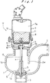
- Next, a conventional vacuum interface valve in the vacuum sewerage system will be described with reference to Figs. 6 and 7. The conventional vacuum interface valve V comprises a
casing 21 having a substantially Y-shaped body, avalve member 22 which is moved up and down in an oblique direction with respect to an axis of the vacuum sewer, and avalve rod 23 for supporting thevalve member 22. Thecasing 21 has aninlet 21i and an outlet 21o which extend in a horizontal direction. On the upper portion of thecasing 21 there is provided ahousing 25 in which apiston 26 is provided so as to perform a reciprocating motion. Thevalve rod 23 is formed, at the upper portion thereof, with ascrew 23a. Thepiston 26 is fixed to thevalve rod 23 by being held between aplate 27 and anut 28 engaging thescrew 23a. - A
diaphragm 29 is provided between thepiston 26 and thehousing 25 to define two chambers, that is, avacuum chamber 25a and anatmospheric chamber 25b. Acompressive coil spring 30 is provided between the upper wall of thehousing 25 and thepiston 26 to urge thepiston 26 obliquely downwardly. - According to the vacuum interface valve V thus constructed, in closing the valve, when the
valve rod 23 is extended downwardly by urging force of thespring 30, thevalve member 22 engages avalve seat 21s formed in thecasing 21 and prevents sewage flow from theinlet 21i to the outlet 21o. - In contrast, in opening the valve, when the
vacuum chamber 25a is communicated with a vacuum source and thevalve rod 23 is retracted by pressure difference between thevacuum chamber 25a and theatmospheric chamber 25b, thevalve member 22 is moved away from thevalve seat 21s and sewage can flow from theinlet 21i to the outlet 21o. - However, in the conventional vacuum interface valve V, since a gap g between the
valve member 22 and the inner wall of thecasing 21 is small, foreign matters F such as gravel are caught between the inner wall of thecasing 21 and thevalve member 22 as shown in Fig. 7 and thevalve member 22 is stuck at a partially opened position. Since the gap g is constant along a stroke of thevalve member 22 to guide thevalve member 22, there is a high possibility that the foreign matters F are caught everywhere during the actuation of thevalve member 22. - Further, when the
valve member 22 is stuck at the partially opened position by existence of the foreign matters F, vacuum in the total sewerage system is lost, resulting in malfunction of the system. - It is an object of the present invention to provide a vacuum interface valve in which wide space can be defined in the vicinity of a valve seat so that foreign matters such as gravel are not caught between the inner wall of the casing and the valve member.
- According to the present invention, there is provided a vacuum interface valve for use in a vacuum sewerage system comprising: a casing having an inlet, an outlet and a valve seat; a valve member provided in the casing and being linearly movable between a position engageable with the valve seat and a position away from the valve seat; means for urging the valve member to cause the valve member to engage the valve seat; and means for lifting the valve member under the action of vacuum to cause the valve member to disengage the valve seat; wherein the casing has an inner wall which is bulged outwardly from the vicinity of the valve seat in a direction substantially perpendicular to an axis of said valve member so that foreign matters are not caught between the inner wall of the casing and the valve member.
- With the above structure, since the inner wall of the casing is bulged outwardly from the vicinity of the valve seat in a direction substantially perpendicular to an axis of the valve member, wide space is defined in the vicinity of the valve seat in the casing. Therefore, foreign matters are not caught between the inner wall of the casing and the valve member, the valve member can be prevented from being stuck at a partially opened position by existence of the foreign matters and the vacuum sewerage system can be always operated in a normal condition. The above and other objects, features and advantages of the present invention will become more apparent from the following description when taken in conjunction with the accompanying drawings in which a preferred embodiment of the present invention is shown by way of an illustrative example.
- In the drawings:
- Fig. 1 is a cross-sectional view of a vacuum interface valve according to a first embodiment of the present invention;
- Fig. 2 is a plan view of a casing in the vacuum interface valve according to the first embodiment of the present invention;
- Fig. 3 is a cross-sectional view showing the manner in which the vacuum interface valve according to the first embodiment of the present invention operates;
- Fig. 4 is a cross-sectional view of a vacuum interface valve according to a second embodiment of the present invention;
- Fig. 5 is a cross-sectional view of a vacuum interface valve according to a third embodiment of the present invention;
- Fig. 6 is a cross-sectional view of a conventional vacuum interface valve; and
- Fig. 7 is a cross-sectional view showing the manner in which the conventional vacuum interface valve operates.
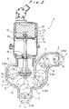
- A vacuum interface valve of the present invention will be described below with reference to Figs. 1 through 3.
- As shown in Figs. 1 and 2, a vacuum interface valve V comprises a
casing 1, avalve member 5 which is moved up and down in a vertical direction, and avalve rod 6 for supporting thevalve member 5. Thecasing 1 has a cylindrical receptacle-like shape comprising abottom wall 1a and acylindrical side wall 1b extending from thebottom wall 1a upwardly. Thecasing 1 is provided with aninlet 2 at the upper portion thereof and anoutlet 3 at the bottom portion thereof. Thecasing 1 is formed with avalve seat 4 at the upper and inner peripheral portion of theoutlet 3. Theinlet 2 and theoutlet 3 have the same inside diameter d. As shown in Figs. 1 and 2, theinlet 2 extends vertically from a position slightly spaced from the central portion of thecasing 1 and extends radially outwardly along the central line 1 (see Fig. 2) after changing the direction at an angle of approximately 90 degrees, and finally is open radially outwardly. In other words, theinlet 2 has aninside wall portion 2w which extends in parallel to an axis x of thevalve member 5 inside thecasing 1. Theoutlet 3 extends vertically downwardly from the central position of thebottom wall 1a. - Therefore, liquid flowing in from the
inlet 2 flows radially inwardly, then changes smoothly its course vertically downwardly, and finally is discharged downwardly from theoutlet 3. Thus, swirling stream is not formed in thecasing 1, which exerts pressure or force on thevalve member 5. - The
casing 1 has thebottom wall 1a and theside wall 1b which are bulged outwardly from the vicinity of thevalve seat 4 in a direction substantially perpendicular to the axis x of thevalve member 5 so that foreign matters such as gravel are not caught between the inner wall of thecasing 1 and thevalve member 5. The bulged degree of thebottom wall 1a and theside wall 1b is arranged so as to have a distance of at least 0.8d between the inner wall of thecasing 1 and the outer periphery of thevalve member 5 when the valve is fully opened. - The
valve member 5 has an approximately conical shape and is supported by thevalve rod 6 extending vertically. On the upper portion of thecasing 1 there is provided ahousing 7 in which apiston 8 is provided so as to perform a reciprocating motion vertically. Thevalve rod 6 is formed, at the upper portion thereof, with ascrew 6a. Thepiston 8 is fixed to thevalve rod 6 by being held between aplate 9 and anut 10 engaging thescrew 6a. - A
diaphragm 11 is provided between thepiston 8 and thehousing 7 to define two chambers, that is, avacuum chamber 7a and anatmospheric chamber 7b. Aweight 13 is provided in thehousing 7 to urge thepiston 8 downwardly. Thevalve member 5 engages thevalve seat 4 by urging force of theweight 13 and prevents sewage flow from theinlet 2 to theoutlet 3. - On the other hand, when the
vacuum chamber 7a is communicated with a vacuum source and thevalve rod 6 is retracted by pressure difference between thevacuum chamber 7a and theatmospheric chamber 7b against gravity of theweight 13, thevalve member 5 is moved upwardly and disengages thevalve seat 4, and thus sewage can flow from theinlet 2 to theoutlet 3. At this time, the gravity of theweight 13 is constant everywhere irrespective of opening degree of the valve, therefore, even if the opening degree of the valve becomes large, there is no need for increasing the degree of vacuum. - Next, operation of the vacuum interface valve of the present invention will be described below with reference to Figs. 1 and 3.
- The suction pipe of the vacuum interface valve V is arranged so that the gap between the lower end of the suction pipe and the bottom of the sump is smaller than the inner diameter d of the
inlet 3 of thecasing 1, in order that the suction pipe or the vacuum interface valve V is not blocked with a foreign matter having a diameter of d or more sucked therein. That is, the foreign matter having a diameter of d or more is checked to enter into the suction pipe by the gap between the suction pipe and the bottom of the sump. The gap is equal to 0.8 to 0.9d, therefore, the maximum diameter of the foreign matter F flowing into the vacuum interface valve V is equal to 0.8 to 0.9d. - In opening the valve, when the
vacuum chamber 7a is communicated with a vacuum source and thevalve rod 6 is retracted by pressure difference between thevacuum chamber 7a and theatmospheric chamber 7b against gravity of theweight 13, thevalve member 5 is moved upwardly and disengages thevalve seat 4, and thus sewage can flow from theinlet 2 to theoutlet 3. - Wide space S is defined in the vicinity of the
valve seat 4 in thecasing 1 so that wide space can be defined with respect to the foreign matter F flowing into thecasing 1 between thevalve member 5 and thebottom wall 1a or theside wall 1b. That is, the distance between thevalve member 5 and the inner wall of thecasing 1 is 0.8d or more when thevalve member 5 takes a fully opened position as shown in Fig. 3, it is possible to ensure area necessary for allowing the foreign matter F to pass therethrough. Incidentally, in Fig. 3, the distance is equal to d as shown by alternate long and short dash line. Thus, the foreign matter F (having a diameter of 0.8d as shown by alternate long and two short dashes line) is prevented from being caught between thevalve member 5 and thecasing 1, and thevalve member 5 is prevented from being stuck by existence of the foreign matter F. Further, the foreign matter flowing in the backside of thevalve member 5 is easily discharged. - The
inlet 2 is disposed at the upper position of theoutlet 3 which is disposed at the lowermost position of thecasing 1, and theinlet 2 has theinside wall portion 2w which extends in parallel to the axis x of thevalve member 5 inside thecasing 1, thus liquid flowing into theinlet 2 flows vertically downwardly in parallel to thevalve rod 6. Consequently, liquid flow does not impinge directly on thevalve member 5, radial force is not applied to thevalve member 5, so that wear of thebearing 15 or looseness of thevalve member 5 can be prevented. Further, since liquid flowing into theinlet 2 reaches theoutlet 3 directly without forming swirling stream, the foreign matter F does not float inside thecasing 1 and an elongated object does not remain in thecasing 1. Even if the foreign matter F having a diameter of 0.8d flows into thecasing 1 as shown in Fig. 3, the flow passage defined from theinlet 2 to theoutlet 3 in thecasing 1 has a sectional area with a diameter of 0.8d or more, therefore, the foreign matter F does not remain in thecasing 1. - On the other hand, the
weight 13 can be utilized as an urging force for closing the valve. To be more specific, when vacuum applied to thevacuum chamber 7a is intercepted, thevalve rod 6 is extended downwardly by the gravity of theweight 13, thevalve member 5 engages avalve seat 4 and prevents sewage flow from theinlet 2 to theoutlet 3. - According to the conventional vacuum interface valve in Fig. 6, in the case where the degree of vacuum applied to the
vacuum chamber 25a is low, thevalve member 22 does not reach a fully opened position due to the urging force of thespring 30 and is stuck at a partially opened position. Thus, the conventional vacuum interface valve is problematic in that area of flow passage of sewage in the casing becomes smaller, resulting in jamming. In contrast, in the present invention, because theweigh 13 can be utilized in order to enable thevalve member 5 to engage thevalve seat 4, the force necessary for lifting thevalve member 5 is constant, and it is easy to lift thevalve member 5 up to a fully opened position. As a result, thevalve member 5 does not remain at the partially opened position, area of flow passage is not restricted. - Fig. 4 shows a second embodiment of the present invention. In the first embodiment of Fig. 1, the
weight 13 is employed as urging means for urging thevalve member 5 downwardly. According to the second embodiment, a compressive coil spring is used as urging means. More specifically, acompressive coil spring 14 is provided between the upper wall of thehousing 7 and thepiston 8. Other structure of the second embodiment is the same as that of the first embodiment, explanation thereof is omitted. - Fig. 5 shows a third embodiment of the present invention. The casing in the third embodiment is different in shape from the
casing 1 in the first embodiment. In this embodiment, the central axis of thecasing 31 is not directed in a vertical direction, but is inclined with respect to the vertical direction. Aninlet 32 and anoutlet 33 of thecasing 31 extends in a horizontal direction. Thecasing 31 is formed with avalve seat 34 at the bottom thereof. Thecasing 31 has abottom wall 31a and aside wall 31b having the same shape as thebottom wall 1a and theside wall 1b of thecasing 1 in Fig. 1 so that wide space S is defined in the vicinity of thevalve seat 34. Theinlet 32 has an inside wall portion 32w which extends in parallel to the axis x of thevalve member 5 inside thecasing 31. Thevalve member 5 in thecasing 31, thehousing 7 and thepiston 8 provided on the upper portion of thecasing 31 are the same as those in Fig. 4. Operation of the vacuum interface valve of this embodiment is the same as that of the valve in Fig. 4. - As is apparent from the above description, according to the present invention, since the inner wall of the casing is bulged from the vicinity of the valve seat in a direction substantially perpendicular to the axis of the valve member, wide space is defined in the vicinity of the valve seat so that foreign matters are not caught between the inner wall of the casing and the valve member. Further, the valve member can be prevented from being stuck at a partially opened position by existence of the foreign matters, the vacuum sewerage system can be always operated in a normal condition.
- Further, according to one aspect of the present invention, since the valve member is vertically moved and the lower surface of the valve member engages the valve seat, the valve rod is vertically provided and the weight can be utilized as urging means of the valve member. By utilizing gravity of the weight, the force for lifting the valve becomes constant, thus facilitating the lift of the valve member up to the fully opened position. As a result, the valve member does not remain at the partially opened position, area of flow passage is not restricted.
- Furthermore, according to one aspect of the present invention, the inlet is disposed above the outlet which is disposed at the lowermost position of the casing and the inlet has the inside wall portion which extends in parallel to the axis x of the valve member inside the casing, thus liquid flowing into the inlet flows vertically downwardly in parallel to the valve rod. Consequently, liquid flow does not impinge directly on the valve member, radial force is not applied to the valve member, so that wear of the bearing or looseness of the valve member can be prevented.
- Although certain preferred embodiments of the present invention have been shown and described in detail, it should be understood that various changes and modification may be made therein without departing from the scope of the appended claims.
Claims (7)
- A vacuum interface valve for use in a vacuum sewerage system comprising:
a casing having an inlet, an outlet and a valve seat;
a valve member provided in said casing and being linearly movable between a position engageable with said valve seat and a position away from said valve seat;
means for urging said valve member to cause said valve member to engage said valve seat; and
means for lifting said valve member under the action of vacuum to cause said valve member to disengage said valve seat;
wherein said casing has an inner wall which is bulged outwardly from the vicinity of said valve seat in a direction substantially perpendicular to an axis of said valve member so that foreign matters are not caught between said inner wall of said casing and said valve member. - The vacuum interface valve according to claim 1, wherein said inlet has an inside diameter of d, a distance between said valve member and said inner wall of said casing is 0.8d or more when said valve member takes a fully opened position.
- The vacuum interface valve according to claim 2, wherein a flow passage defined from said inlet to said outlet in said casing has a sectinal area with a diameter of 0.8d or more.
- The vacuum interface valve according to claim 1, wherein said casing has a cylindrical receptacle-like shape comprising a bottom wall and a cylindrical side wall extending from the bottom wall upwardly, said valve seat is located at a central portion of said bottom wall.
- The vacuum interface valve according to claim 4, wherein said outlet is located at a central portion of said casing, and said inlet has an inside wall portion which extends in parallel to an axis of said valve member.
- The vacuum interface valve according to claim 1, wherein said valve member is movable vertically, said urging means comprises a weight having a predetermined weight.
- The vacuum interface valve according to claim 1, wherein said valve member is movable vertically, said urging means comprises a spring.
Applications Claiming Priority (2)
| Application Number | Priority Date | Filing Date | Title |
|---|---|---|---|
| JP31226491 | 1991-11-27 | ||
| JP312264/91 | 1991-11-27 |
Publications (2)
| Publication Number | Publication Date |
|---|---|
| EP0544261A1 true EP0544261A1 (en) | 1993-06-02 |
| EP0544261B1 EP0544261B1 (en) | 1996-10-23 |
Family
ID=18027152
Family Applications (1)
| Application Number | Title | Priority Date | Filing Date |
|---|---|---|---|
| EP92120102A Expired - Lifetime EP0544261B1 (en) | 1991-11-27 | 1992-11-25 | Vacuum interface valve |
Country Status (5)
| Country | Link |
|---|---|
| US (1) | US5292104A (en) |
| EP (1) | EP0544261B1 (en) |
| JP (1) | JPH05240373A (en) |
| AT (1) | ATE144572T1 (en) |
| DE (1) | DE69214775T2 (en) |
Cited By (2)
| Publication number | Priority date | Publication date | Assignee | Title |
|---|---|---|---|---|
| EP0646740A1 (en) * | 1993-09-22 | 1995-04-05 | Ebara Corporation | Vacuum valve |
| DE102017117904A1 (en) * | 2017-08-07 | 2019-02-07 | Gemü Gebr. Müller Apparatebau Gmbh & Co. Kommanditgesellschaft | Valve body for an angle seat valve |
Families Citing this family (4)
| Publication number | Priority date | Publication date | Assignee | Title |
|---|---|---|---|---|
| JP3854433B2 (en) * | 1999-09-16 | 2006-12-06 | シーケーディ株式会社 | Vacuum proportional on-off valve |
| DE102008021748B4 (en) * | 2008-04-30 | 2010-02-04 | Vab Vakuum Anlagen Bau Gmbh | Vacuum valve, in particular for sewer systems |
| DE102012204044A1 (en) * | 2012-03-15 | 2013-09-19 | Schaeffler Technologies AG & Co. KG | Adjustable coolant pump with a multi-part modular design |
| CN112392115B (en) * | 2020-11-11 | 2022-04-26 | 宁波市北仑大矸建筑工程有限公司 | Municipal administration sewage drainage system |
Citations (5)
| Publication number | Priority date | Publication date | Assignee | Title |
|---|---|---|---|---|
| FR7774E (en) * | 1903-08-11 | 1907-10-11 | Chappee Et Fils Soc | New urban sanitation system |
| FR11156E (en) * | 1909-04-28 | 1909-12-21 | Joseph Pire | Advanced device for lifting liquids and its application |
| FR477567A (en) * | 1914-06-20 | 1915-10-28 | Jean Chabanel | Installation for the evacuation and treatment of waste |
| DE1459592A1 (en) * | 1961-01-16 | 1969-04-24 | Wilhelm Strate | Method and device for lifting waste water |
| EP0445462A1 (en) * | 1990-03-09 | 1991-09-11 | Burton Mechanical Contractors, Inc. | Electric air admission controller |
Family Cites Families (11)
| Publication number | Priority date | Publication date | Assignee | Title |
|---|---|---|---|---|
| US642154A (en) * | 1897-03-27 | 1900-01-30 | Thomas O Perry | Thermostatically-operated valve-motor. |
| FR402491A (en) * | 1909-04-28 | 1909-10-09 | Joseph Pire | Advanced device for lifting liquids and its application |
| DE550090C (en) * | 1930-11-26 | 1932-05-13 | Johann Zagorski Dr Ing | Valve housing |
| US2685426A (en) * | 1949-06-15 | 1954-08-03 | Edward Valves Inc | Valve body with material flow guide and inclined seat structure |
| US4171853A (en) * | 1977-07-15 | 1979-10-23 | Burton Mechanical Contractors | Vacuum operated sewerage system |
| GB2149534B (en) * | 1983-11-08 | 1986-12-10 | Cowells Sewerage Systems Limit | Liquid level control system |
| US5082238B1 (en) * | 1989-06-15 | 1996-05-07 | Burton Mech Contractors | Nonjamming vacuum valve having tapered plunger |
| JP2546722B2 (en) * | 1989-08-31 | 1996-10-23 | 株式会社荏原製作所 | Vacuum type waste water collecting device and branch pipe connecting structure of vacuum waste water pipe for the device |
| JPH0388621A (en) * | 1989-08-31 | 1991-04-15 | Ebara Corp | Vacuum type sewage water collection device and vacuum value controller therefor |
| JP2546721B2 (en) * | 1989-08-31 | 1996-10-23 | 株式会社荏原製作所 | Opening and closing power extraction structure of vacuum valve for vacuum type waste water collection device |
| JPH03250128A (en) * | 1990-02-28 | 1991-11-07 | Ebara Corp | Vacuum soil pipe laying structure of vacuum type waste water collecting device |
-
1992
- 1992-11-24 US US07/980,924 patent/US5292104A/en not_active Expired - Fee Related
- 1992-11-24 JP JP4336571A patent/JPH05240373A/en active Pending
- 1992-11-25 EP EP92120102A patent/EP0544261B1/en not_active Expired - Lifetime
- 1992-11-25 DE DE69214775T patent/DE69214775T2/en not_active Expired - Fee Related
- 1992-11-25 AT AT92120102T patent/ATE144572T1/en active
Patent Citations (5)
| Publication number | Priority date | Publication date | Assignee | Title |
|---|---|---|---|---|
| FR7774E (en) * | 1903-08-11 | 1907-10-11 | Chappee Et Fils Soc | New urban sanitation system |
| FR11156E (en) * | 1909-04-28 | 1909-12-21 | Joseph Pire | Advanced device for lifting liquids and its application |
| FR477567A (en) * | 1914-06-20 | 1915-10-28 | Jean Chabanel | Installation for the evacuation and treatment of waste |
| DE1459592A1 (en) * | 1961-01-16 | 1969-04-24 | Wilhelm Strate | Method and device for lifting waste water |
| EP0445462A1 (en) * | 1990-03-09 | 1991-09-11 | Burton Mechanical Contractors, Inc. | Electric air admission controller |
Cited By (3)
| Publication number | Priority date | Publication date | Assignee | Title |
|---|---|---|---|---|
| EP0646740A1 (en) * | 1993-09-22 | 1995-04-05 | Ebara Corporation | Vacuum valve |
| US5575454A (en) * | 1993-09-22 | 1996-11-19 | Ebara Corporation | Vacuum valve |
| DE102017117904A1 (en) * | 2017-08-07 | 2019-02-07 | Gemü Gebr. Müller Apparatebau Gmbh & Co. Kommanditgesellschaft | Valve body for an angle seat valve |
Also Published As
| Publication number | Publication date |
|---|---|
| US5292104A (en) | 1994-03-08 |
| JPH05240373A (en) | 1993-09-17 |
| EP0544261B1 (en) | 1996-10-23 |
| DE69214775D1 (en) | 1996-11-28 |
| ATE144572T1 (en) | 1996-11-15 |
| DE69214775T2 (en) | 1997-05-28 |
Similar Documents
| Publication | Publication Date | Title |
|---|---|---|
| US4489746A (en) | Backflow preventer apparatus | |
| FI93667C (en) | Vacuum Drainage Device | |
| EP0544261B1 (en) | Vacuum interface valve | |
| EP0821753A1 (en) | Sump-vented controller mechanism for vacuum sewerage transport system | |
| EP0415360B1 (en) | Vacuum-type sewage collecting apparatus | |
| US4523607A (en) | Backflow preventer apparatus | |
| KR100390294B1 (en) | Vacuum valve | |
| EP1860245A1 (en) | Sewage lifting station especially for domestic sewage | |
| JP3869573B2 (en) | Vacuum sewage system | |
| US5765595A (en) | Air/vacuum valve throttling apparatus | |
| JP2008121253A (en) | Vacuum type draining system | |
| US6283140B1 (en) | Waste fluid discharge column | |
| CN212317092U (en) | Sewage tank ventilation type vacuum well | |
| EP0530203B1 (en) | Improvement in a sewage system | |
| JP2001081852A (en) | Vacuum sewage system | |
| JP2001098537A (en) | Suspended matter recovery device | |
| JPH06174147A (en) | Vacuum valve | |
| JP2000170936A (en) | Intake and exhaust valve | |
| KR101099312B1 (en) | Vacuum fluid transfer system | |
| JP2651789B2 (en) | Breather pipe with sewage inflow prevention mechanism | |
| EP4022140A1 (en) | A urinal outlet conduit | |
| JP2000074242A (en) | Valve | |
| JP2001049733A (en) | Simple and easy vacuum valve unit | |
| PL163770B1 (en) | System for draining off liquids in particular in vacuum sewerage | |
| JPH08145218A (en) | Exhaust valve device for vacuum drainage collecting and discharging tank |
Legal Events
| Date | Code | Title | Description |
|---|---|---|---|
| PUAI | Public reference made under article 153(3) epc to a published international application that has entered the european phase |
Free format text: ORIGINAL CODE: 0009012 |
|
| AK | Designated contracting states |
Kind code of ref document: A1 Designated state(s): AT BE CH DE DK ES FR GB GR IT LI LU MC NL PT SE |
|
| 17P | Request for examination filed |
Effective date: 19931125 |
|
| 17Q | First examination report despatched |
Effective date: 19950411 |
|
| GRAG | Despatch of communication of intention to grant |
Free format text: ORIGINAL CODE: EPIDOS AGRA |
|
| GRAH | Despatch of communication of intention to grant a patent |
Free format text: ORIGINAL CODE: EPIDOS IGRA |
|
| GRAH | Despatch of communication of intention to grant a patent |
Free format text: ORIGINAL CODE: EPIDOS IGRA |
|
| GRAA | (expected) grant |
Free format text: ORIGINAL CODE: 0009210 |
|
| AK | Designated contracting states |
Kind code of ref document: B1 Designated state(s): AT BE CH DE DK ES FR GB GR IT LI LU MC NL PT SE |
|
| PG25 | Lapsed in a contracting state [announced via postgrant information from national office to epo] |
Ref country code: IT Free format text: LAPSE BECAUSE OF FAILURE TO SUBMIT A TRANSLATION OF THE DESCRIPTION OR TO PAY THE FEE WITHIN THE PRESCRIBED TIME-LIMIT;WARNING: LAPSES OF ITALIAN PATENTS WITH EFFECTIVE DATE BEFORE 2007 MAY HAVE OCCURRED AT ANY TIME BEFORE 2007. THE CORRECT EFFECTIVE DATE MAY BE DIFFERENT FROM THE ONE RECORDED. Effective date: 19961023 Ref country code: ES Free format text: THE PATENT HAS BEEN ANNULLED BY A DECISION OF A NATIONAL AUTHORITY Effective date: 19961023 Ref country code: GR Free format text: LAPSE BECAUSE OF FAILURE TO SUBMIT A TRANSLATION OF THE DESCRIPTION OR TO PAY THE FEE WITHIN THE PRESCRIBED TIME-LIMIT Effective date: 19961023 Ref country code: DK Effective date: 19961023 Ref country code: LI Free format text: LAPSE BECAUSE OF FAILURE TO SUBMIT A TRANSLATION OF THE DESCRIPTION OR TO PAY THE FEE WITHIN THE PRESCRIBED TIME-LIMIT Effective date: 19961023 Ref country code: BE Effective date: 19961023 Ref country code: CH Free format text: LAPSE BECAUSE OF FAILURE TO SUBMIT A TRANSLATION OF THE DESCRIPTION OR TO PAY THE FEE WITHIN THE PRESCRIBED TIME-LIMIT Effective date: 19961023 Ref country code: AT Effective date: 19961023 |
|
| REF | Corresponds to: |
Ref document number: 144572 Country of ref document: AT Date of ref document: 19961115 Kind code of ref document: T |
|
| ET | Fr: translation filed | ||
| REF | Corresponds to: |
Ref document number: 69214775 Country of ref document: DE Date of ref document: 19961128 |
|
| PG25 | Lapsed in a contracting state [announced via postgrant information from national office to epo] |
Ref country code: LU Free format text: LAPSE BECAUSE OF NON-PAYMENT OF DUE FEES Effective date: 19961130 |
|
| PG25 | Lapsed in a contracting state [announced via postgrant information from national office to epo] |
Ref country code: SE Effective date: 19970123 Ref country code: PT Effective date: 19970123 |
|
| REG | Reference to a national code |
Ref country code: CH Ref legal event code: PL |
|
| PG25 | Lapsed in a contracting state [announced via postgrant information from national office to epo] |
Ref country code: MC Effective date: 19970531 |
|
| PLBE | No opposition filed within time limit |
Free format text: ORIGINAL CODE: 0009261 |
|
| STAA | Information on the status of an ep patent application or granted ep patent |
Free format text: STATUS: NO OPPOSITION FILED WITHIN TIME LIMIT |
|
| 26N | No opposition filed | ||
| REG | Reference to a national code |
Ref country code: GB Ref legal event code: IF02 |
|
| PGFP | Annual fee paid to national office [announced via postgrant information from national office to epo] |
Ref country code: GB Payment date: 20021112 Year of fee payment: 11 |
|
| PGFP | Annual fee paid to national office [announced via postgrant information from national office to epo] |
Ref country code: FR Payment date: 20021114 Year of fee payment: 11 |
|
| PGFP | Annual fee paid to national office [announced via postgrant information from national office to epo] |
Ref country code: DE Payment date: 20021128 Year of fee payment: 11 |
|
| PGFP | Annual fee paid to national office [announced via postgrant information from national office to epo] |
Ref country code: NL Payment date: 20021130 Year of fee payment: 11 |
|
| PG25 | Lapsed in a contracting state [announced via postgrant information from national office to epo] |
Ref country code: GB Free format text: LAPSE BECAUSE OF NON-PAYMENT OF DUE FEES Effective date: 20031125 |
|
| PG25 | Lapsed in a contracting state [announced via postgrant information from national office to epo] |
Ref country code: NL Free format text: LAPSE BECAUSE OF NON-PAYMENT OF DUE FEES Effective date: 20040601 |
|
| PG25 | Lapsed in a contracting state [announced via postgrant information from national office to epo] |
Ref country code: DE Free format text: LAPSE BECAUSE OF NON-PAYMENT OF DUE FEES Effective date: 20040602 |
|
| GBPC | Gb: european patent ceased through non-payment of renewal fee |
Effective date: 20031125 |
|
| PG25 | Lapsed in a contracting state [announced via postgrant information from national office to epo] |
Ref country code: FR Free format text: LAPSE BECAUSE OF NON-PAYMENT OF DUE FEES Effective date: 20040730 |
|
| NLV4 | Nl: lapsed or anulled due to non-payment of the annual fee |
Effective date: 20040601 |
|
| REG | Reference to a national code |
Ref country code: FR Ref legal event code: ST |