EP0546865A2 - Digital video signal recording/playback apparatus - Google Patents
Digital video signal recording/playback apparatus Download PDFInfo
- Publication number
- EP0546865A2 EP0546865A2 EP92311370A EP92311370A EP0546865A2 EP 0546865 A2 EP0546865 A2 EP 0546865A2 EP 92311370 A EP92311370 A EP 92311370A EP 92311370 A EP92311370 A EP 92311370A EP 0546865 A2 EP0546865 A2 EP 0546865A2
- Authority
- EP
- European Patent Office
- Prior art keywords
- data
- frame
- intra
- frame compression
- playback
- Prior art date
- Legal status (The legal status is an assumption and is not a legal conclusion. Google has not performed a legal analysis and makes no representation as to the accuracy of the status listed.)
- Granted
Links
Images


Classifications
-
- H—ELECTRICITY
- H04—ELECTRIC COMMUNICATION TECHNIQUE
- H04N—PICTORIAL COMMUNICATION, e.g. TELEVISION
- H04N21/00—Selective content distribution, e.g. interactive television or video on demand [VOD]
- H04N21/20—Servers specifically adapted for the distribution of content, e.g. VOD servers; Operations thereof
- H04N21/23—Processing of content or additional data; Elementary server operations; Server middleware
- H04N21/236—Assembling of a multiplex stream, e.g. transport stream, by combining a video stream with other content or additional data, e.g. inserting a URL [Uniform Resource Locator] into a video stream, multiplexing software data into a video stream; Remultiplexing of multiplex streams; Insertion of stuffing bits into the multiplex stream, e.g. to obtain a constant bit-rate; Assembling of a packetised elementary stream
-
- H—ELECTRICITY
- H04—ELECTRIC COMMUNICATION TECHNIQUE
- H04N—PICTORIAL COMMUNICATION, e.g. TELEVISION
- H04N5/00—Details of television systems
- H04N5/76—Television signal recording
- H04N5/91—Television signal processing therefor
- H04N5/92—Transformation of the television signal for recording, e.g. modulation, frequency changing; Inverse transformation for playback
-
- G—PHYSICS
- G11—INFORMATION STORAGE
- G11B—INFORMATION STORAGE BASED ON RELATIVE MOVEMENT BETWEEN RECORD CARRIER AND TRANSDUCER
- G11B15/00—Driving, starting or stopping record carriers of filamentary or web form; Driving both such record carriers and heads; Guiding such record carriers or containers therefor; Control thereof; Control of operating function
- G11B15/02—Control of operating function, e.g. switching from recording to reproducing
- G11B15/12—Masking of heads; circuits for Selecting or switching of heads between operative and inoperative functions or between different operative functions or for selection between operative heads; Masking of beams, e.g. of light beams
- G11B15/125—Masking of heads; circuits for Selecting or switching of heads between operative and inoperative functions or between different operative functions or for selection between operative heads; Masking of beams, e.g. of light beams conditioned by the operating function of the apparatus
-
- H—ELECTRICITY
- H04—ELECTRIC COMMUNICATION TECHNIQUE
- H04N—PICTORIAL COMMUNICATION, e.g. TELEVISION
- H04N19/00—Methods or arrangements for coding, decoding, compressing or decompressing digital video signals
- H04N19/60—Methods or arrangements for coding, decoding, compressing or decompressing digital video signals using transform coding
- H04N19/61—Methods or arrangements for coding, decoding, compressing or decompressing digital video signals using transform coding in combination with predictive coding
-
- H—ELECTRICITY
- H04—ELECTRIC COMMUNICATION TECHNIQUE
- H04N—PICTORIAL COMMUNICATION, e.g. TELEVISION
- H04N19/00—Methods or arrangements for coding, decoding, compressing or decompressing digital video signals
- H04N19/85—Methods or arrangements for coding, decoding, compressing or decompressing digital video signals using pre-processing or post-processing specially adapted for video compression
- H04N19/88—Methods or arrangements for coding, decoding, compressing or decompressing digital video signals using pre-processing or post-processing specially adapted for video compression involving rearrangement of data among different coding units, e.g. shuffling, interleaving, scrambling or permutation of pixel data or permutation of transform coefficient data among different blocks
-
- H—ELECTRICITY
- H04—ELECTRIC COMMUNICATION TECHNIQUE
- H04N—PICTORIAL COMMUNICATION, e.g. TELEVISION
- H04N19/00—Methods or arrangements for coding, decoding, compressing or decompressing digital video signals
- H04N19/85—Methods or arrangements for coding, decoding, compressing or decompressing digital video signals using pre-processing or post-processing specially adapted for video compression
- H04N19/89—Methods or arrangements for coding, decoding, compressing or decompressing digital video signals using pre-processing or post-processing specially adapted for video compression involving methods or arrangements for detection of transmission errors at the decoder
-
- H—ELECTRICITY
- H04—ELECTRIC COMMUNICATION TECHNIQUE
- H04N—PICTORIAL COMMUNICATION, e.g. TELEVISION
- H04N21/00—Selective content distribution, e.g. interactive television or video on demand [VOD]
- H04N21/40—Client devices specifically adapted for the reception of or interaction with content, e.g. set-top-box [STB]; Operations thereof
- H04N21/43—Processing of content or additional data, e.g. demultiplexing additional data from a digital video stream; Elementary client operations, e.g. monitoring of home network or synchronising decoder's clock; Client middleware
- H04N21/434—Disassembling of a multiplex stream, e.g. demultiplexing audio and video streams, extraction of additional data from a video stream; Remultiplexing of multiplex streams; Extraction or processing of SI; Disassembling of packetised elementary stream
-
- H—ELECTRICITY
- H04—ELECTRIC COMMUNICATION TECHNIQUE
- H04N—PICTORIAL COMMUNICATION, e.g. TELEVISION
- H04N5/00—Details of television systems
- H04N5/76—Television signal recording
- H04N5/91—Television signal processing therefor
- H04N5/92—Transformation of the television signal for recording, e.g. modulation, frequency changing; Inverse transformation for playback
- H04N5/926—Transformation of the television signal for recording, e.g. modulation, frequency changing; Inverse transformation for playback by pulse code modulation
- H04N5/9261—Transformation of the television signal for recording, e.g. modulation, frequency changing; Inverse transformation for playback by pulse code modulation involving data reduction
- H04N5/9264—Transformation of the television signal for recording, e.g. modulation, frequency changing; Inverse transformation for playback by pulse code modulation involving data reduction using transform coding
-
- H—ELECTRICITY
- H04—ELECTRIC COMMUNICATION TECHNIQUE
- H04N—PICTORIAL COMMUNICATION, e.g. TELEVISION
- H04N5/00—Details of television systems
- H04N5/76—Television signal recording
- H04N5/91—Television signal processing therefor
- H04N5/93—Regeneration of the television signal or of selected parts thereof
- H04N5/94—Signal drop-out compensation
- H04N5/945—Signal drop-out compensation for signals recorded by pulse code modulation
-
- H—ELECTRICITY
- H04—ELECTRIC COMMUNICATION TECHNIQUE
- H04N—PICTORIAL COMMUNICATION, e.g. TELEVISION
- H04N9/00—Details of colour television systems
- H04N9/79—Processing of colour television signals in connection with recording
- H04N9/80—Transformation of the television signal for recording, e.g. modulation, frequency changing; Inverse transformation for playback
- H04N9/804—Transformation of the television signal for recording, e.g. modulation, frequency changing; Inverse transformation for playback involving pulse code modulation of the colour picture signal components
- H04N9/8042—Transformation of the television signal for recording, e.g. modulation, frequency changing; Inverse transformation for playback involving pulse code modulation of the colour picture signal components involving data reduction
-
- G—PHYSICS
- G11—INFORMATION STORAGE
- G11B—INFORMATION STORAGE BASED ON RELATIVE MOVEMENT BETWEEN RECORD CARRIER AND TRANSDUCER
- G11B15/00—Driving, starting or stopping record carriers of filamentary or web form; Driving both such record carriers and heads; Guiding such record carriers or containers therefor; Control thereof; Control of operating function
- G11B15/18—Driving; Starting; Stopping; Arrangements for control or regulation thereof
- G11B15/1808—Driving of both record carrier and head
- G11B15/1875—Driving of both record carrier and head adaptations for special effects or editing
-
- H—ELECTRICITY
- H04—ELECTRIC COMMUNICATION TECHNIQUE
- H04N—PICTORIAL COMMUNICATION, e.g. TELEVISION
- H04N19/00—Methods or arrangements for coding, decoding, compressing or decompressing digital video signals
- H04N19/10—Methods or arrangements for coding, decoding, compressing or decompressing digital video signals using adaptive coding
- H04N19/102—Methods or arrangements for coding, decoding, compressing or decompressing digital video signals using adaptive coding characterised by the element, parameter or selection affected or controlled by the adaptive coding
- H04N19/103—Selection of coding mode or of prediction mode
- H04N19/107—Selection of coding mode or of prediction mode between spatial and temporal predictive coding, e.g. picture refresh
-
- H—ELECTRICITY
- H04—ELECTRIC COMMUNICATION TECHNIQUE
- H04N—PICTORIAL COMMUNICATION, e.g. TELEVISION
- H04N5/00—Details of television systems
- H04N5/76—Television signal recording
- H04N5/78—Television signal recording using magnetic recording
- H04N5/782—Television signal recording using magnetic recording on tape
- H04N5/783—Adaptations for reproducing at a rate different from the recording rate
Definitions
- the present invention relates generally to a digital signal recording/playback apparatus, and more particularly, to a variable length code recording in the digital signal recording/playback apparatus.
- FIGURES 1(a) and 1(b) illustrate diagrams for explaining relations of the positions on a screen and the positions on the recording tracks of a recording medium in VCRs.
- FIGURE 1(a) indicates the positions on the screen and
- FIGURE 1(b) indicates the positions on the recording tracks.
- FIGURE 1(a) illustrates one frame of picture vertically divided into eight sections.
- FIGURE 1(b) indicates the record positions of the first through ninth tracks similarly divided into eight tracks.
- Video data are recorded in order on a recording medium starting from the lowest line position A of the first track to its top line position I, For instance, when recording one frame data on one track, data displayed in a horizontal section defined by lines a and b on a screen are recorded on a longitudinal section defined by lines A and B on a recording medium, and thereafter, in the similar manner data displayed in horizontal sections defined by lines b through i on the screen are recorded in the order on longitudinal sections defined by lines B through I on the recording medium.
- FIGURES 2(a) through 2(d) are diagrams for illustrating the relationship between trace patterns and playback signal envelopes in data recording at a triple speed.
- FIGURE 2(a) illustrates trace patterns when playback data at triple speed with a head scanning time shown at the axis of abscissas and track pitch or tape traveling distance at the axis of coordinates.
- the signs "+” and “-” in the diagram indicate differentially oriented normal azimuths of the playback head, respectively. Further, numerals in the diagram show track numbers; thus odd number tracks are in the plus azimuth and even number tracks are in the minus azimuth.
- FIGURES 2(b) through 2(d) indicate the signal envelope played back by the ordinary head, the playback envelope by the special purpose head and the synthetic playback envelope obtained by both heads.
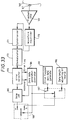
- FIGURE 3 is a diagram for illustrating the construction of the recording/playback heads.
- a rotary cylinder 3 as shown in FIGURE 3, is used for the data recording and playback operations.
- the rotary cylinder 3 is equipped with a pair of regular heads 1, 1 which have differentiated azimuths with each other and a pair of special purpose heads 2, 2 which have also differentiated azimuths with each other, and further the azimuths of one regular head 1 and its adjacent special purpose head 2 are also differentiated each other.
- the first track and the third track are traced by the regular head 1 of the plus azimuth in the initial scanning period (tracing period), and the fourth track and the sixth track are traced by the regular head 1 of the minus azimuth in the next scanning period.
- the playback signal envelope shown in FIGURE 2(b) is obtained by the regular head 1. Further, the second track is traced by the special purpose head 2 in the initial scanning period and the playback signal envelope shown in FIGURE 2(c) is obtained in the same manner. By combining the playback output from the regular head 1 with the playback output from the special purpose head 2, the synthetic playback envelope shown in FIGURE 2(d) is obtained.
- Table 1 shown below indicates relations among the playback outputs at the triple speed playback operation (FIGURE 2(d)), the traces of head and the corresponding positions on the screen.
- Table 1 Playback Track 1 Frame/1 Track 1 Frame/2 Tracks Track Frame Track Frame #1 1st Frame #1 1st Frame 1 (A) - (C) (a) - (c) (A) - (C) (a) - (c) #2 2nd Frame #2 1st Frame 2 (C) - (G) (c) - (g) (C) - (G) (f) - (h) #3 3rd Frame #3 2nd Frame 3 (G) - (I) (g) - (i) (G) - (I) (d) - (e) #4 4th Frame #4 2nd Frame 4 (A) - (C) (a) - (c) (A) - (C) (e) - (f) #5 5th Frame #5 3rd Frame 5 (C) - (G) (c)
- data A through C on the first track #1 are played back by the regular head 1 in the first quarter (1/4) time interval in the initial scanning period
- data of C through G on the second track #2 are played back by the special purpose head 2 in the next half (1/2) time interval
- data of G through I on the third track are played back by the regular head 1 in the next 1/4 time interval.
- data on three tracks are played back in the similar manner in one scanning period.
- the positions of A through C on the first track #1 correspond to the positions a through c on the first frame of image
- the positions C through G on the second track #2 correspond to the positions c through g on the second frame of the frame
- the positions G through 1 on the third track #3 correspond to the positions g through i on the third frame of the image, as shown in Table 1. Therefore, in the playback operation at a triple speed, the picture patterns at the positions on the first through the third frames are combined and displayed as a playback picture.
- the positions A through C on the first track #1 correspond to the positions a and b on the first frame
- the positions C through G on the second track #2 correspond to the positions f through h on the first frame
- the positions G through I on the third track #3 correspond to the positions d through e on the second frame as shown in Table 1.
- the positions A through C on the fourth track #4 correspond to the positions e and f on the second frame
- the positions C through G on the fifth track #5 correspond to the positions b through d on the third frame
- the positions G through I on the sixth track #6 correspond to the positions h through i on the third frame.
- the picture patterns at the positions on the first through the third frames are presented in mix on the playback picture as shown in FIGURE 4(b).
- the high efficient encoding technique is to encode video data at more lower bit rate for improving efficiency of digital transmission and recording.
- the CCITT Cometi Consultafif international Verizonique et Telephonique (International Telegraph and Telephone Consultative Committee)
- the encoding is made by using the frame I processed an intra-frame compression and the frame P processed an inter-frame compression (or a predictive frame compression).
- FIGURE 5 is a diagram for explaining the video data compression according to the CCITT recommendation.
- the frame I processed intra-frame compression is the one frame video data encoded by the DCT (Digital Cosine Transformation) processing.
- the inter-frame Compression processed frame P is the video data encoded by the predictive encoding method using the intra-frame compression processed frame I or the inter-frame compression processed frame P. In addition, more lowering of bit rate has been made by encoding these encoded data to the data encoded in variable length.
- the intra-frame compression processed frame I was encoded by the intra-frame information only, it is possible to decode it by a single encoded data only.
- the inter-frame compression processed frame P was encoded using the correlation with other video data, it cannot be decoded by a single encoded data only.
- FIGURE 6 is a block diagram for illustrating the recording section of a conventional apparatus for recording/playback variable length codes using such the predictive encoding.
- a luminance signal Y and color difference signals Cr and Cb are applied to a multiplexer 11, where they are multiplexed in a block of 8 pixels x 8 horizontal scanning lines.
- Sampling rate of the color difference signals Cr and Cb in the horizontal direction is a half (1/2) of the luminance signal Y. Therefore, in the period when two 8 x 8 luminance blocks are sampled, one 8 x 8 block of the color difference signals Cr and Cb is sampled.
- two luminance signal blocks Y1 and Y2 and each of the color difference signal blocks Cr and Cb total, thus four blocks in total forms a macro block.
- two luminance signal blocks Y1 and Y2 and each of the color difference blocks Cr and Cb represent the same position of the picture frame.
- the output of the multiplexer 11 is applied to a DCT (Digital Cosine Transformation) circuit 13 through a subtracter 12.
- DCT Digital Cosine Transformation
- a switch 14 When performing the intra-frame compression, a switch 14 is kept OFF and the output of the multiplexer 11 is applied directly to the DCT circuit 13 as described later.
- a signal composed of 8 x 8 pixels per block is applied to the DCT circuit 13.
- the DCT circuit 13 converts the input signal into frequency components by the 8 x 8 two dimensional DCT processing This makes it possible to reduce the spatial correlative components. That is, the output of the DCT circuit 13 is applied to a quantizer 15 which lowers one block signal redundancy by requantizing the DCT output using a fixed quantization coefficient. Further, block pulses are supplied to the multiplexer 11, the DCT circuit 13, the quantizer 15, etc. which operate in block unit.
- the quantized data from the quantizer 15 is applied to a variable length encoder 16 and is, for instance encoded to the Huffman codes based on the result calculated from the statistical encoding amount of the quantized output. As a result, a short bit is assigned to data having a high appearance probability and a long bit to data having a low appearance probability and thus, transmission amount is further reduced.
- the output of the variable length encoder 16 is applied to an error correction encoder 17, which provides the output from the variable length encoder 16 with an error correction parity added to a multiplexer 19.
- the output of the variable length encoder 16 is also applied to an encoding controller 18.
- the amount of the output data varies largely depending on input picture. So, the encoding controller 18 monitors the amount of the output data from the variable length encoder 16 end regulates the amount of the output data by controlling the quantization coefficient of the quantizer 15. Further, the encoding controller 18 may restrict the amount of the output data by controlling the variable length encoder 16.
- a sync/ID generator 20 generates frame a sync signal and ID signal showing data contents and additional information and provides them to the multiplexer 19.
- the multiplexer 19 forms 1 sync block data with a sync signal, ID signal, compressed signal data and parity and provides this data to the recoding/encoder which is not shown the recording/encoder, after recording/encoding the output from the multiplexer 19 according to characteristic of a recording medium, records the encoded data on a recording medium (not shown).
- the inter-frame encoding is carried out to encode differential data using redundancy of inter-frame picture.
- a differential value is made small by compensating the motion by obtaining a difference at the pixel position corresponding to the motion vector while detecting the motion vector by obtaining the position of the preceding frame corresponding to the fixed position of the current frame.
- the output of the quantizer 15 is also applied to an inverse quantizer 21.
- This quantized output is inverse-quantized in the inverse quantizer 21 and further, inverse DCT processed in an inverse DCT circuit 22 and restored to the original video signal. Further, the original information cannot be played back completely in the DCT processing, requantization, inverse quantization and inverse DCT processing and part of the information lacks.
- the output of the subtracter is a differential information
- the output of the inverse DCT circuit 22 is also a differential information.
- the output of the inverse DCT circuit 22 is applied to an adder 23. This output from the adder 23 is fed back through a variable delay circuit 24 which delays signal by about one frame period and a motion compensator 25, and the adder 23 restores the current frame data by adding differential data to the preceding frame data and provides them to the variable delay circuit 24.
- the preceding frame data from the variable delay circuit 24 and the current frame data from the multiplexer 11 are applied to a motion detector 26 where motion vector is detected.
- the motion detector 26 obtains motion vector through the full search motion detection by, for instance, a matching calculation.
- the full search type motion detection the current frame is divided into the fixed number of blocks and the search range of, for instance, 15 horizontal pixels x 8 vertical pixels are set for each block.
- the search range corresponding to the preceding frame the matching calculation is carried out for each block and an inter-pattern approximation is calculated. Then, by calculating the preceding frame block which provides the minimum distortion in the search range, the vector which is obtained by this block and the current frame block is detected as the motion vector.
- the motion detector 26 provides the motion vector thus obtained to the motion compensator 25.
- the motion compensator 25 extracts a corresponding block data from the variable delay circuit 24, corrects it according to the motion vector and provides it to the subtracter 12 through the switch 14 and also, to the adder 23 after making the time adjustment.
- the motion compensated preceding frame data is supplied from the motion compensator 25 to the subtracter 12 through the switch 14 and when the switch 14 is ON, the inter-frame compression mode results and if the switch 14 is OFF, the intra-frame compression mode results.
- the switch 14 is turned ON/OFF based on a motion judging signal. That is, the motion detector 26 generates the motion judging signal depending on whether the motion vector size is in excess of a fixed threshold value and outputs it to a logic circuit 27.
- the logic circuit 27 controls the ON/OFF of the switch 17 by the logical judgment using the motion judging signal and a refresh periodic signal.
- the refresh periodic signal is a signal showing the intra-frame compression processed frame I illustrated in FIGURE 5. If the input of the intra-frame compression processed frame I is indicated by the refresh periodic signal, the logic circuit 27 turns the switch 14 OFF irrespective of the motion judging signal.
- the logic circuit 27 turns the switch 14 OFF and the intra-frame encoding is carried out for each block even when the inter-frame compression processed frame P data are input.
- Table 2 shown below indicates the ON/OFF control of the switch 14 by the logic circuit 27.
- Table 2 Frame I Intra-Frame Compression Switch 14 OFF Processed Frame Frame P Motion Vector Detected Switch 14 ON Inter-Frame Compression Processed Frame Motion Vector Unknown Switch 14 OFF Inter-Frame Compression Processed Frame
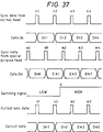
- FIGURE 8 is a diagram for illustrating the data stream of record signals which are output from the multiplexer 19.
- the first and the sixth frames of the input video signal are converted to the intra-frames I1 and I6, respectively and the second through the fifth frames are converted to the inter-frame compression processed frames P1 through P5.
- the ratio of data amount between the intra-frame compression processed frame I and the inter-frame compression processed frame P is (3 - 10) : 1.
- the amount of data of the intra-frame compression processed frame I is relatively much while the amount of data of the inter-frame compression processed frame P is extremely reduced. Further, the data of the inter-frame compression processed frame P cannot be decoded unless other frame data are decoded.
- FIGURE 9 is a block diagram indicating the decoding section (playback section) of a conventional variable length code recorder.
- Compressed encoded data recorded on a recording medium is played back by the playback head which is not shown and applied into an error correction decoder 31.
- the error correction decoder 31 corrects errors produced in data transmission and recording.
- the playback data from the error correction decoder 31 are applied to a variable length data decoder 33 through a code buffer memory 32 and decoded to fixed length data. Further, the code buffer memory 32 may be omitted.
- the output from the variable length decoder 33 is inverse quantized in an inverse quantizer 34, inverse DCT processed and decoded to the original video signal in an inverse DCT circuit 35, and applied to the terminal a of a switch 36.
- the output of the variable length decoder 33 is also applied to a header signal extractor 37.
- the header signal extractor 37 retrieves a header showing whether the input data is the intra-frame compression data or the inter-frame compression data and provides it to the switch 36. When supplied with a header shown the intra-frame compression data, the switch 36 selects the terminal a and outputs decoded data from the inverse DCT circuit 35.
- the inter-frame compression data is obtained by adding the output from the inverse DCT circuit 35 and the preceding frame output from the predictive decoder 39 using an adder 38. That is, the output of the variable length decoder 33 is applied to a motion vector extractor 40 and the motion vector is thus obtained this motion vector is applied to a predictive decoder 39.
- the decoded output from the switch 36 is delayed for one frame period by a frame memory 41.
- the predictive decoder 39 compensates the preceding frame decoded data from the frame memory 41 according to the motion vector and provides them to the adder 38.
- the adder 38 decodes the inter-frame compression data by adding the output from the predictive decoder 39 and the output from the inverse DCT circuit 35 and provides the decoded inter-frame compression data to the terminal b of the switch 36.
- the switch 36 selects the terminal b by the header and outputs the decoded data from the adder 38.
- the compression and expansion are carried out without delay.
- the intra-frame compression processed frame I and the inter-frame compression processed frame P differ in encoded amount and if the data stream shown in FIGURE 8 is recorded on a recording medium, one frame is not necessarily able to play back by the playback data in the playback operation at a triple speed. Further, the inter-frame compression processed frame P processed inter-frame compression will become not able to playback if any undecoded frame is generated as in the playback operation at a triple speed because it cannot be decoded for an independent frame.
- variable length code recorder has such a problem of that the picture quality of a picture played back in the special playback operation deteriorates extremely because each frame data is in variable length and some frame data of a single frame only cannot be decoded.
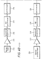
- FIGURE 10 is a diagram for explaining a broadcasting system adopted for video-conference, video-telephone, etc.
- video signals from cameras are high efficiency encoded in an encoder 151 and added with an error correction code in an error correction encoder 152 corresponding to a transmission line 154.
- a transmission modulator 153 modulates the output from the error correction encoder 152 corresponding to the transmission line 154 and then, provides it to the transmission line 154 after converting into electric waves.
- signals being applied through the transmission line 154 are demodulated in a receiving demodulator 155.
- An error corrector 156 corrects errors generated in the transmission line 154 and feeds them to a switch 157 and also to a VCR 158.
- the VCR 158 records the input signals or plays back the signals and feeds them to the switch 157.
- the switch 157 is switched by an input switching signal based on user operation and selecting the output of the error corrector 156 or that of the VCR 158, provides it to a decoder 159.
- the decoder 159 decodes the high efficiency encoded signals to original signals and an error corrector 160 corrects errors remaining in the decoded output without being corrected and provides them to a monitor TV set (not shown).
- the broadcasting signals applied through the transmission line 154 or playback signals from the VCR 158 are displayed on the screen of the monitor TV set.
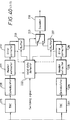
- FIGURE 11 is a block diagram for illustrating the construction of a VCR which is capable of high efficiency encoding and decoding. Further, the VCR shown in FIGURE 10 is in the same construction as the right to the broken line in FIGURE 11.
- Video signals are high efficiency encoded in an encoder 161 and then applied to an error correction encoder 162.
- the error correction encoder 162 provides the encoded data with an error correction parity code adapted to a VCR added to an adder 163.
- the adder 163 adds a synchronizing signal and ID signal generated in an ID generator 164 to the output of the error correction encoder 162 and provides the output to a recording/modulator 165.
- the recording/modulator 165 modulates this output to adapt to the recording by a recording medium and provides it to a recording amplifier 166.
- This recording amplifier 166 amplifies the modulated signals and feeds them to a magnetic head 167 for recording on a tape 168.
- the tape 168 is traced by the magnetic head 167 to play back recorded signals and the playback signals are supplied to a playback amplifier 169.
- the playback signals from the playback amplifier 169 are waveform equalized in a waveform equalizer 170 to reduce inter-code interference and then applied to a synchronizer 171.
- the synchronizer 171 restores the playback data in unit of recorded data train and feeds them to a demodulator 172.
- the demodulator 172 demodulates the playback data and feeds them to an error corrector 173.
- the error corrector 173 corrects errors in the playback data and provides to a decoder 174.
- the decoder 174 and an error corrector 175 are in the construction identical to those of the decoder 159 and the error corrector 160 shown in FIGURE 10, and decodes the output of the error corrector 173 and after correcting errors, outputs the error corrected output.
- the switch 157 shown in FIGURE 10 selects the VCR 158.
- Data transmitted from a broadcasting station via the transmission line 154 are supplied to the VCR 158.
- Data transmitted from a broadcasting station via the transmission line 154 are supplied to the error corrector 156.
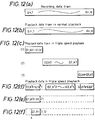
- the recording data train shown in FIGURE 12(a) is applied to the VCR 158.
- the subscript n denoted track number and the subscript m denotes recorded data train number. That is, Gn, m denote the mth data train on the nth track.
- the reencoded data train will become identical to the playback data train in the normal playback operation as shown in FIGURE 12(b).
- data is played back by the magnetic head while crossing the tracks in the playback operation at triple speed as described above and therefore, the playback data does not agree with the recorded data. That is, as shown in FIGURE 12(c), the k0 data train through the k1 data train are played back on the first track, the k2 through k3 data trains are played back on the second track, and the k4 through k5 data trains are played back on the third track.
- the VCR 158 carries out the demodulation, error correction and decoding processes of this playback data.
- data decoding processes of this playback data As data decoding processes of this playback data.
- data may not be played back correctly at such portions where the recording tracks are switched and furthermore, the playback data trains become discontinuous at switching points of the recording tracks, data around the track switching points cannot be used for decoding.
- video data are recorded with a synchronizing signal and ID signal added and demodulated in unit of synchronizing signal in the synchronizer 171 when played back and therefore, if data are not played back in the middle of a synchronizing block, it is possible to demodulate data from the start position of next synchronizing block.
- the portion shown by the broken line in FIGURE 12(d) of playback data by one scanning in the triple speed playback operation is not output against FIGURE 12(c).
- a monitor TV set is not able to reconstruct images using these data and simply displays images in order of input image data
- data trains being transmitted are variable length encoded data trains
- data length of the broken lined part shown in FIGURE 12(d) is known, it is not possible to identify the start position of next data train k2's. Accordingly, it is not possible to display playback images using all playback outputs from the VCR 158 on the screen of a monitor TV set and information data are not used effectively even when and error flag is added to them. That is, in such a system as video-telephone, which decodes input data trains continuously, if data are interrupted, subsequent data cannot be used efficiently.
- decoding may be enabled for a fixed period of the top of a track by specifying the top of the track as the start position of a data train as shown in FIGURE 12(e). This will make it possible to decode a data train G1, KO' through G1, K1'. Further, FIGURE 12(f) illustrates an example where the data position with a ⁇ mark was set as the data train start position. In this case, the data train G1, 11 through G1, 12 can be decoded.
- FIGURE 13 A playback signal processing method which is capable of special playback operation using the above special playback heads is shown in FIGURE 13.
- a signal played back by a playback head 210 is amplified in an amplifier 211 and supplied to a detector 250 and a switch 223.
- a signal played back by a special purpose head 216 is amplified in an amplifier 17 and supplied to a detector 251 and the switch 223.
- the detectors 250 and 251 envelop constituents of respective signals are detected and provide them to an amplitude comparator 252.
- amplitudes of these two signals are compared and the result is supplied to a switch 253.
- a switching signal is also supplied to the switch 253 and either one of these signals is selected by a mode selecting signal and supplied to the switch 223 as a control signal.
- the switch 223 selects one of the outputs from the amplifiers 211 and 217 according to this control signal and supplies to a demodulator 224 where the output signal is demodulated. This demodulated signal is restored to the original image signal in a playback processor 254.
- the switching signal described above is used to select a preset head output signal and if this signal is selected by the switch 253, the outputs from the amplifiers 211 and 217 are selected alternately.
- a signal in larger amplitude normally selected in the amplitude comparator 252 . Therefore, if the output of the amplitude comparator 252 is selected by the mode selecting signal in the switch 253, the output in larger amplitude of those outputs from the amplifiers 211 and 217 is selected in the switch 223.
- FIGURE 14 illustrates trace patterns in the playback operation at triple speed.
- the tracks are aslant on a tape
- the trace of the head is vertical to the traveling direction of a tape because of triple speed. Therefore, the trace of the head extends over the tracks b, c and d.
- data on Trace 1 is played back by selecting data played back, for instance, by the playback heads from S to A out of Trace 1, by the special purpose heads from A to B and by the playback heads from B to E.
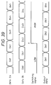
- FIGURE 15(a) indicates data played back by the playback head and FIGURE 15(B) is data played back by the special purpose head.
- "SY”, "ID”, “D” and “PA” indicate synchronizing signal, ID signal, data and parity signal, respestively. And, from “SY” through “PA” form one block.
- the switching points are set at the points A and B, signals are switched in the middle of data D. If the switching point is A, signals are synchronized as the positions of both "SY" are in accord with each other but data is invalid because the tracks are different. So, the portion of a in (a) and the portion of b in FIGURE 15(b) become invalid data. If the switching point is B, signals are not synchronized as both of two "SY" are out of position. As described above, if the switching point is preset or set according to the amplitude, invalid data was produced before and after the switching point and in addition, signals could not be synchronized is some cases.
- the present invention therefore seeks to provide an apparatus for recording/playback digital data with variable length codes which is capable of obtaining the stabilized quality of specially playback picture even when intra-frame compression data and inter-frame compression data are available.
- the present invention also seeks to provide an apparatus for recording/playback digital data with variable length codes which is capable of improving efficiency of image played back by transmitting encoded data with a virtual signal fitted for an image playback apparatus inserted into error portions.
- the present invention still also seeks to provide an apparatus for recording/playback digital data with variable length codes which is capable of improving quality of pictures when they are specially played back by making the most of data which were invalid so far.
- a digital signal recording/playback apparatus includes a data rearranging circuit for rearranging the intra-frame compression data in the variable length encoded data and an address and a data length adding circuit for adding addresses and data length information of the intra-frame compression data output from the data rearrangement circuit.
- the data rearranging circuit includes a circuit for rearranging the inter-frame compression data in the variable length encoded data in unit of a sync block of recorded codes.
- a third aspect of the apparatus for recording/playback digital data with variable length codes which are encoded from intra-frame compression data and inter-frame compression data includes a data rearranging circuit for uniformly rearranging all data by combining the intra-frame compression data and the inter-frame compression data into one frame data and varying the arrangement of the one frame data in the intra-frame compression data at a frame unit and a circuit for adding address information and data length information of the intra-frame compression data included in the data rearranging circuit.
- the data rearranging circuit includes a circuit for dividing the one frame data into a predetermined number of data sections which are comprised of the intra-frame compression data and the inter-frame compression data, and a circuit for uniformly arranging all of the intra-frame compression data by varying the arrangement of the intra-frame compression data in the each data section in frame unit.
- a fifth aspect of the apparatus for recording/playback digital data with variable length codes which are encoded from intra-frame compression data and inter-frame compression data includes an encoder having an address information generater for generating address information for each block of high efficiency encoded data and a multiplexer for multiplexing the address information onto the encoded data.
- a sixth aspect of the apparatus for recording/playback digital data with variable length codes which are encoded from intra-frame compression data and inter-frame compression data includes a decoder having an error detecting means for detecting errors in high efficiency encoded data comprising address information multiplexed on an encoded data for each block, a zero data generator for generating zero data in block unit with an error flag added, a switch for selectively outputing the encoded data or the output from the zero data generator, a controller for controlling the switch to replace a transmission data error block with an output from the zero data generator by detecting an error block address from the detected result of the error detector and an invalid data inserting circuit for inserting invalid data between the encoded data and the zero data in order to maintain an output data rate of the switch constant.
- a seventh aspect of the apparatus for recording/playback digital data with variable length codes which are encoded from intra-frame compression data and inter-frame compression data includes at least two ordinary video heads provided on a rotating drum for ordinary playback operation, at least two special video heads provided adjacent to the ordinary video heads, respectively, for use only in special playback operation, a first playback processor for playing back compression encoded digital signals by the ordinary video heads, a second playback processor for playing back compression encoded digital signals by the special video heads, a generator for generating a control signal by obtaining a switching point where invalid data is least produced through a calculation based on outputs from the first and second playback processors a selector for selecting either one of the outputs of the first and second playback processing means based on the control signal, and a decoder for decoding video signals based on the output from the selector.
- FIGURES 16 through 41 The present invention will be described in detail with reference to the FIGURES 16 through 41.
- reference numerals or letters used in FIGURES 1 through 15 will be used to designate like or equivalent elements for simplicity of explanation.
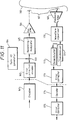
- FIGURE 16 is a block diagram for illustrating an embodiment of the recording section (encoding section) of the variable length code recorder according to the present invention.
- FIGURE 17 is a block diagram for illustrating an embodiment of the playback section (decoding section) of the variable length code recorder of the present invention.
- the same component parts as in the FIGURES 6 and 9 are assigned with the same sings. This embodiment is applied to a recorder which performs the intra-frame compression for each frame.
- FIGURE 18(a) indicates the division of the intra-frame area
- FIGURE 18(b) indicates the arrangement of the intra-frame compression processed frame and the inter-frame compression processed frame
- FIGURES 18(c) through 18(f) indicate the data format of a recording signal.
- the intra-frame compression processed frame I is divided into five parts horizontally or vertically and the divided parts are referred to as i1, i2, i3, i4 and i5, respectively.
- the intra-frame compression processed frame I is constructed for every six frames. That is, the frames are arranged in order of the intra-frame compression processed frame I1, inter-frame compression processed frames P1 through P5, intra-frame compression processed frame I7, . and so on.
- the intra-frame compression processed frame I is divided into five parts and five frames P are continued between the intra-frames I. Further, it is desirable that the number of divided parts of the intra-frame compression processed frame I and the number of continuous data of the inter-frame compression processed frame P are at a fixed ratio.
- the data stream after the compression is arranged in order of I1 (i1) (data corresponding to the part i1 of the intra-frame compression processed frame I), I1 (i2), . . (I1 (i5), P2, P3, . and so on a as shown in FIGURE 18(c). Further, the time division of the data streams I1 (i1) through I) (i5) by processing in a time sequence may not be possible.
- the data stream shown in FIGURE 18(c) is converted into the arrangement shown in FIGURE 18(d). That is, it is arranged in such combinations as Data I1 (i1) and Data P2, Data I1 (i2) and Data P3, Data I1 (i3) and Data P4, Data I1 (i4) and Data P5, Data I1 (i5) and Data P6, Vietnamese and so on.
- the data combination is so set that the data rate becomes almost constant.
- a macro block is divided into two to correspond to one sync block.
- a macro block may be divided to a set of the luminance signals Y1, Y2 and a set of the color difference signals Cb, Cr to correspond to a sync block.
- a macro block may be divided to a set of the luminance signal Y1 and the color difference signal Cb and a set of the luminance signal Y2 and the color difference signal Cr to correspond to a sync block.
- Each macro block corresponds to a fixed sync block in this way.
- the macro block which is processed by the intra-frame compression process is added with such information as ID showing its number and address to compare its macro block with the frame position and macro block data length as shown in FIGURE 18(f). If these data do not satisfy one sync block length, a sync block is composed with the inter-frame compression processed frame P data added in order and an error correction parity added lastly.
- the data of sections i1 through i5 of the intra-frame compression processed frame I1 is uniformly arranged at regular intervals and following the data in the section 15, the data of the sections i1 through i5 of the intra-frame compression processed frame I7 is uniformly arranged.
- the data of the sections i1 through i5 of the intra-frame compression processed frames I1 and I7 is arranged at regular intervals in the unit of macro block.
- each of the macro blocks is added with its address and data length to facilitate to clearly grasp a sync block corresponding to a fixed macro block.
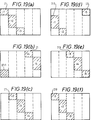
- FIGURES 19(a) through 19(f) are diagrams for explaining the tracing of the intra-frame compression processed frames in the playback operation at a triple speed.
- FIGURES 19(a) through 19(f) show the reproducing positions of the first to the sixth tracings by the oblique lines, respectively.
- one frame data is recorded on one track, that is, it is assumed that the amount of data of one frame is equivalent to the amount of data of one track as an average.
- the played back synthetic playback envelope of the tracks #1, #2 and #3 is obtained in the first tracing.
- the inter-frame compression data is for differential picture and cannot be output even when it is decoded by performing the inverse quantization process and the inverse DCT process unless the preceding frame data is played back.
- the intra-frame compression data can be directly used by decoding it. If the intra-frame compression data is uniformly arranged on the recording tracks and error rates of the playback section are above the tolerance, it is able to playback and a playback picture is predictable when the playback position is decided. If the tracing position is definite, a picture capable of playback can be grasped certainly.
- the tracks #1, #2 and #3 are traced in the first tracing and the data of the section i1 through i3 of the intra-frame compression processed frame I1 iq played back.
- the tracks #4, #5 and #6 are traced and the data of the section i4 and i5 of the intra-frame compression processed frame I1 and those of the section i5 of the intra-frame compression processed frame I7 is played back as shown in FIGURE 19(b).
- the tracks #7, #8 and #9 are traced and the data of the sections i2 through i4 of the intra-frame compression processed frame I7 is played back as shown in FIGURE 19(c).
- the tracks #10, #11 and #12 are traced and the data of the section i5 of the intra-frame compression processed frame I7 and the data of the sections i1 and i2 of the intra-frame compression processed frame I13 is played back as shown in FIGURE 19(d).
- the tracks #13, #14 and #15 are traced and the data of the sections i3 through i5 of the frame I13 is played back as shown in FIGURE 19(e).
- the sixth tracing the same parts as in the first tracing are traced, that is, the data of sections i1 through i3 of the intra-frame compression processed frame I19 is played back as shown in FIGURE 19(f). From the least common multiple 15 of the number of division [5] of the intra-frame compression processed frame and the playback speed [3], it is seen that all data is played back by the tracing of 15 tracks.
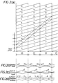
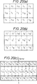
- FIGURES 20(a) through 20(c) are diagrams for illustrating the composition of a playback picture.
- FIGURE 20(a) shown the composition according to the tracing method shown in FIGURES 19(a) through 19(f) and
- FIGURES 20(b) and 20(c) shown the composition according to the tracing method in another embodiment described later.
- FIGURE 20(a) when the tracing method shown in FIGURES 19(a) through 19(f) is used, all sections of one frame picture are played back by the first through the fifth tracings and a picture is composed by the playback data of the sections of the intra-frame compression processed frames I1, I7 and I13.
- FIGURES 21(a) through 21(k) are diagrams for explaining the tracing of the intra-frame compression processed frame for recording one frame picture by dividing it to two tracks in the triple speed playback operation.
- FIGURES 21(a) through 21(k) illustrate the first through eleventh tracings, respectively.
- FIGURES 22(a) through 22(e) are diagrams for illustrating an output frame picture.
- one frame data is divided to be recorded on two tracks, one frame passes in two tracings. That is, the section to be updated for each frame in the playback operation is for two tracings and the section to be updated for five frames are as shown in FIGURES 22(a) through 22(e). As shown in FIGURES 21(a) through 21(k) and FIGURES 22(a) through 22(e), all sections of one frame are played back in 10 times tracings.
- a luminance signal Y and color difference signals Cr and Cb are applied to a multiplexer 11.
- the multiplexer I1 multiplexes the input signals in unit of eight (8) pixels x eight (8) horizontal scanning lines per block and also, multiplexes them in unit of macro block consisting of two luminance signal blocks Y and each one color difference signal block Cr and Cb and provides them to a subtracter 12.
- the subtracter 12 is supplied with the proceeding frame data through a switch 14, and subtracting the preceding frame data from the output from the multiplexer 11 at a time of the inter-frame compression process, provides the result to a DCT circuit 13, while provides the output from the multiplexer 11 directly to the DCT circuit 13 at a time of the intra-frame compression process.
- the DCT circuit 13 processes the output of the subtracter 12 through the 8 x 8 two-dimensional DCT process and provides the result to a quantizer 15.
- the quantizing coefficient of the quantizer 15 is controlled by an encoding controller 18, which lowers a bit rate by quantizing the output of the DCT circuit 14 using the quantizing coefficient and provides it to a variable length encoder 50.
- the variable length encoder 50 under the control of the encoding controller 18, further lowers the bit rate by converting the input data to variable length codes and provides it to a multiplexer 51 and an inter-frame compression data memory 52. Further, the variable length encoder 50 generates an MH signal for each macro block and provides it to an address generation and data length measuring circuit 53.
- the encoding controller 18 changes the quantizing coefficient based on the output from the variable length encoder 50 and at the same time, limits the total amount of codes by limiting the number of bits of the output of the variable length encoder 50. Further, block pulses are supplied to the multiplexer 11, the DCT circuit 13, the quantizer 15, etc. which perform the processing in block unit.
- the output of the quantizer 15 is applied to an inverse quantizer 21.
- This inverse quantizer 21 provides the quantized output after inverse quantizing to an inverse DCT circuit 22.
- the inverse DCT circuit 22 restores the output of the inverse quantizer 21 to the original data before DCT processing and provides the result to an adder 23.
- the output of the adder 23 is fed back through a variable delay circuit 24 which delays for one frame period and and then applies to a motion compensator 25, and the adder 23 restores the original data before the processing of differential data by the subtracter 12 by adding the differential data of the current frame with the proceeding frame data and provides the restored data to the variable delay circuit 24.
- the output of the variable delay circuit 24 is also applied to a motion detector 26.
- the motion detector 26 is also supplied with the output from the multiplexer 11 and obtaining a motion vector by the matching calculation by, for instance, the full search motion vector detection, provides it to the motion compensator 25 and the same time, provides a motion judging signal, which is based on whether a distortion value by the matching calculation is in excess of a fixed threshold value, to a motion logic circuit 27.
- the motion compensator 25 corrects the output of the variable delay circuit 24 based on the motion vector and provides the motion corrected preceding frame data to the subtracter 12 through the switch 14.
- the motion logic circuit 27 controls the ON/OFF of the switch 14 based on the motion judging signal and a refresh periodic signal indicating the intra-frame compression processed frame.
- the refresh periodic signal is also applied to the address generation and data length measuring circuit 53.
- the address generation and data length measuring circuit 53 Supplied with the refresh periodic signal indicating the intra-frame compression processed frame I and the MB signal, the address generation and data length measuring circuit 53 generates address for every MB signal in the intra-frame compression processed frame I and measures data length between MB signals. Macro block address and data length contained in the data of the sections i1 through i5 of the frame I1, I7 and I13 obtained by the address generation and data length measuring circuit 53 are applied to the multiplexer 51.
- the multiplexer 51 multiplexes macro block address and data length to the intra-frame compression data from the variable length encoder 50 and provides the result to the intra-frame compression data memory 57.
- the intra-frame compression data memory 57 stores the intra-frame compression data from the multiplexer 51 and the intra-frame compression data memory 52 stores the inter-frame compression data from the variable length encoder 50 and provides them to the multiplexer (hereinafter referred to as the MPX) 58.
- the memory P controller 54 and the memory I controller 55 control the write to the inter-frame compression data memory 52 and the intra-frame compression data memory 57 based on the data from the address generation and data length measuring circuit 53.
- the output of the address generation and data length measuring circuit 53 is also applied to the data rearrangement controller 56 which rearranges the data stream shown in FIGURE 18(c) by controlling the memory P controller 54, the memory 1 controller 55 and the MPX 58. That is, the MPX 58, under the control of the data rearrangement controller 56, multiplexes macro block address, data length, as shown in FIGURES 18(d) through 18(f), and intra-frame compression data for each sync block and multiplexing inter-frame compression data from the inter-frame compression data memory 52 to the remaining range of one sync block, provides the result to the error correction encoder 17.
- the error correction encoder 17 provides this input with an error correction parity added to the multiplexer 19.
- the sync/ID generator 20 generates a sync signal and ID signal and provides them to the multiplexer 19.
- the multiplexer 19 provides these sync signal and ID signals by adding to the output of the MPX 58.
- the output of the multiplexer 19 is recorded on a recording medium through the recording head which is not shown.
- the data played back from a recording medium by the playback head which is not shown is applied to a demultiplexer (hereinafter referred to as the DMPX) 62 and an address and data length extractor 61 after the error correction in the error corrector (not shown).
- the address and data length extractor 61 extracts address of a macro block and its data length added for each sync block to the DMPX 52 and a header extractor 63.
- the DMPX 62 is controlled based on a macro block data length and separating the input data to the intra-frame compression data and the inter-frame compression data and provides them to variable length decoders 64 and 65, respectively.
- variable length decoders 64 and 65 decode the intra-frame compression data and inter-frame compression data, respectively and provide them to the header extractor 63 and at the same time, provide the decoded outputs to an intra-frame buffer 66 and an inter-frame buffer 67, respectively.
- the header extractor 63 receives the decoded intra-frame compression data, the decoded inter-frame compression data, address and data length of a macro block, and provides an indicating signal to restore the time sequence of the decoded data to an intra-frame compression data rearrangement canceller 68, a memory I controller 69 and a memory P controller 70.
- the memory I controller 69 and the memory P controller 70 control the read/write of the intra-frame buffer 66 and the inter-frame buffer 67 based on the indicating signal and the outputs from the intra-frame compression data rearrangement canceller 68.
- the outputs from the intra-frame buffer 66 and the inter-frame buffer 67 are applied to an MPX 71, which in turn restores the input data to the original data stream shown in FIGURE 18(c) and provides it to the inverse quantizer 34 and the motion vector extractor 40.
- the construction of the recorder composed of the inverse quantizer 34 which inversely quantizes input signals, the inverse DCT circuit 35 which processes the inverse-DCT on the output of the inverse quantizer 34, the header signal extractor 37 which extracts the header signal, the motion vector extractor 40 which extracts motion vector, the frame memory 41 which delays the output signal for one frame period, the predictive decoder 39 which compensates the output of the frame memory 41 for motion, the adder 38 which decodes the inter-frame compression data by adding the output from the inverse DCT circuit 35 with the output from the predictive decoder 39 and the switch 36 which switches and provides the decoded intra-frame compression data and the decoded inter-frame compression data is the same as before.
- the processes up to the variable length encoder 50 at the recording section are the same as before. That is, the luminance signal Y and the color difference signals Cr and Cb are multiplexed in unit of 8 pixels x 8 horizontal scanning lines per block and further, multiplexed in the unit of macro block consisting of total four blocks of two luminance signal blocks Y and each one of color difference signal block Cr and Cr by the multiplexer 11 and applied to the subtracter 12.
- the switch 14 is turned OFF, the output from the multiplexer 11 is DCT processed in the DCT circuit 13, quantized in the quantizer 15 and a bit rate is lowered.
- the quantized output is applied to the variable length encoder 50 where is is encoded in variable length and is applied to the multiplexer 51.
- the output of the quantizer 15 is fed back to the subtracter 12 after delayed for one frame period through the inverse quantizer 21, the inverse DCT circuit 2, the variable delay circuit 24, the motion compensator 25 and the switch 14 and when preparing inter-frame compression data, the subtracter 12 subtracts the preceding frame data from the output of the multiplexer 11 and provides a difference to the DCT circuit 13. Data rate of this differential data is lowered by the DCT circuit 13 and the quantizer 15, converted into variable length codes and applied to the inter-frame compression data memory 52.
- variable length encoder 50 generates an MB signal for each macro block and provides it to the address generation and data length measuring circuit 53.
- the address generation and data length measuring circuit 53 is supplied with the refresh period signal indicating the intra-frame compression processed frame I, generates an address for every MH signal (for every macro block) in the intra-frame compression processed frame I and measures data length between MB signals (a data length of a macro block).
- the multiplexer 51 is supplied with addresses and data lengths from the address generation and data length measuring circuit 53 and provides the macro blocks composing the sections i1 through i5 of the intra-frame compression processed frame with the addresses and data lengths (see FIGURE 18(f)) to the intra-frame compression data memory 57.
- the address generation and data length measuring circuit 53 controls the memory P controller 94, the memory I controller 55 and the data rearrangement controller 56, and the memory P controller 54 and the memory I controller 55 are further controlled by the data rearrangement controller 56.
- the inter-frame compression data memory 52 and the intra-frame compression data memory 57 are controlled by the memory P controller 54 and the memory I controller 55, respectively for the data read/write, and provide the stored data to the MPX 58.
- the data rearrangement controller 56 also controls the MPX 58 and rearranging the data stream illustrated in FIGURE 18(c), provides it after converting into the array illustrated in FIGURE 18(d).
- the output of the MPX 58 is added with a parity for error correction by the error correction encoder 17, added with a sync signal and ID in the multiplexer 19 and is converted to the data train as shown in the FIGURES 18(d) through 18(f).
- the output from the multiplexer 19 is recorded in a recording medium through the recording head which is not shown.
- intra-frame compression data is divided into five sections, each of which makes a set with inter-frame compression data and is uniformly arranged in the unit of sync block, intra-frame compression data is uniformly recorded on a recording medium.
- the playback output from a recording medium which is not shown is applied to the address and data length extractor 61 and the DMPX 62 illustrated in FIGURE 17 after correction errors, if any.
- the intra-frame compression data was uniformly recorded on a recording medium, it is possible to play back all parts of the intra-frame compression data by restoring the number of frames based on the number of fractions of the intra-frame compression processed frame, the playback speed, and the number of tracks, on which one frame picture is recorded even when a special playback operation was carried out.
- the address and data length extractor 61 extracts the macro block address and data length added to each sync block.
- the DMPX 62 is controlled based on a data length supplied from the address and data length extractor 61 and separating the intra-frame compression data and the inter-frame compression data, provides them to the variable length decoders 64 and 65, respectively.
- the variable length decoders 64 and 65 decode the input data to fixed length data and provides them to the intra-frame buffer 66 and the inter-frame buffer 67, respectively.
- the decoded data from the variable length decoders 64 and 75 is also applied to the header extractor 63.
- the header extractor 63 is also supplied with the output from the address and data length extractor 61 and preparing an indicating signal to restore a time sequence to the original data, provides it to the memory I controller 69, the memory P controller 70 and the intra-frame compression data rearrangement canceller 68.
- the intra-data rearrangement canceller 68 controls the memory I controller 69, the memory P controller 70 and the MPX 71 based on the indicating signal and header information.
- the memory I controller 69 and the memory P controller 70 control read/write of the intra-frame buffer 66 and the inter-frame buffer 67 and provide the intra-frame compression data and inter-frame compression data converted to a fixed length to the MPX 71.
- the MPX 71 is controlled by the intra-data rearrangement canceller 68 and outputs a data array illustrated in FIGURE 18(c), that is, a data array in which five frames of inter-frame compression data are continued between the intra-frame compression data is output.
- the subsequent operations are the same as before.
- the decoded intra-frame compression data is applied to the terminal a of the switch 36 by the inverse quantizer 34 and the inverse DCT circuit 35
- the decoded inter-frame compression data is applied to the terminal b of the switch 36 from the adder 38 which adds the decoded preceding frame data from the predictive decoder 39 with the output from the inverse DCT circuit 35.
- the switch 36 switches the terminals a and b under the control by the header signal extractor 37 and outputs the decoding output.
- FIGURE 23 is a block diagram showning another embodiment of the present invention.
- the same component parts as FIGURE 16 are assigned with the same signs and the explanation will be omitted.
- This embodiment is applied to the system which extracts intra-frame compression data and inter-frame compression data from high efficiency encoded data and rearrange the intra-frame compression data from the extracted information to each sync block.
- the high efficiency encoded input signal is applied to the DMPX 83 and also, to the header extraction and I/P identifier 81 through the buffer 82.
- the header and I/P identifier 81 identifies whether the input data is intra-frame compression data or inter-frame compression data and extracts its address.
- the buffer 82 provides the input signal to the DMPX 83 and the data length measuring circuit 84 after delaying it for the processing time interval of the header extraction and I/P identifier 81.
- the DMPX 83 is controlled by the header extraction and I/P identifier 81, separated intra-frame compression data and inter-frame compression data and provides them to the multiplexer 51 and the inter-frame compression data memory 52, respectively. Further, depending upon the header information adding method, the header extraction and I/P identifier 81 may construct a decoder.
- the data length measuring circuit 84 measures data lengths of macro blocks and provides them to the multiplexer 86, and the address generator 85 generates addresses for macro blocks and provides them to the multiplexer 86.
- the multiplexer 86 multiplexes addresses and data lengths of macro blocks and provides the results to the multiplexer 51. Further, the output of the header extraction and I/P identifier 81 is also applied to the memory P controller 54, the memory I controller 5 and the data rearrangment controller 56. Other constructions are the same as those in FIGURE 16.
- the header extraction and I/P identifier 81 identifies whether the input data is intra-frame compression data or inter-frame compression data, and the DMPX 83, under the control of the header extraction and I/P identifier 81, provides the inter-frame compression data to the inter-frame compression data memory 52 and the intra-frame compression data to the multiplexer 51.
- the data length measuring circuit 54 under the control by the header extraction and I/P identification 81, measures data lengths of macro blocks from the output of the buffer 82, and the address generator 85 generates address for every macro block from the output of the header extraction and I/P identifier 81. Addresses and data lengths of macro blocks are multiplexed in the multiplexer 86 and are applied to the multiplexer 51. The subsequent operations are the same as those in the embodiment shown in FIGURE 16.
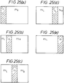
- FIGURE 24 is a diagram for illustrating the encoding in another aspect of the embodimet according to the present invention.
- FIGURES 25(a) through 25(e) are diagrams for illustrating the operation of FIGURE 24 by separating it for every one frame.
- the intra-frame compression processed frame I is divided into five sections and these divided sections I1 through I5 are arranged in the fixed area of the inter-frame compression processed frame P. That is, the frame #1 is composed of the data of the section I1 of the intra-frame compression processed frame and the data of the section PIR of the inter-frame compression processed frame, and in the frame #2, the data of the section I2 of the intra-frame compression processed frame is arranged between the inter-frame compression processed frames P2L and P2R.
- the intra-frame compression processed frames I3 and I4 are arranged between the inter-frame compression processed frames P3L and P3R and the inter-frame compression processed frames P4L and P4R, respectively, and in the frame #5 , the inter-frame compression processed frame P5L and the intra-frame compression processed frame I5 are arranged.
- all areas of the intra-frame compression processed frame can be encoded by five frames.
- FIGURES 26(a) through 26(c) are diagrams for illustrating the data stream in the above embodiment.
- each frame is composed of the plural number of sync blocks.
- Each sync block is composed of the data of the intra-frame section and the data of inter-frame section.
- intra-frame compression data is arranged with a sync signal, ID, address and data length and parity added.
- FIGURE 20(b) the frame construction in this embodiment is as illustrated in FIGURE 20(b). That is, in the frame #1, the leftmost and top intra-frame section I1, the center frame section I2 which is the second section from the left and the lowest section I3 which is the third section from the left of the five divided sections are played back successively, and in the frame #2, the intra-frame compression processed frame I4 on the top of the second column from right which is the second frame from the right, the intra-frame compression processed trace I5 on the center of the most right column and the intra-frame compression processed frame I6 on the bottom of most left column are played back successively. Thereafter, all the sections are played back in the same manner and one complete frame is composed of 1I5 sections.
- the circuit construction in thin embodiment is the same as that shown in FIGURES 16, 17 and FIGURES 18(a) through 18(f), but there is such a merit in which the buffer memory capacity is reducible.
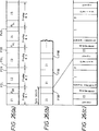
- FIGURES 27(a) through 27(c) are diagrams for illustrating the encoding in another aspect of the embodiment according to the present invention.
- FIGURES 27(a) and 27(b) shows the frames #1 and #2, respectively and
- FIGURE 27(c) shows the frame #5.
- one frame picture is divided into m (2 in this embodiment) parts and each of m divided parts is further divided into five sections.
- the data arranging method is the same as that shown in FIGURES 25(a) through 25(e).
- the intra-frame compression data I is arranged at each end of the left and right inter-frame compression data P as illustrated in FIGURE 27(a).
- FIGURES 28(a) through 28(d) are diagrams for illustrating the data stream in the above embodiment.
- FIGURE 29 is a diagram to show the contrast of the frame picture with the data stream illustrated in FIGURES 28(a) through 28(d).
- each frame is composed of the intra-frame compression data zI and the inter-frame compression data P.
- the intra-frame compression data I, I' are arranged between the inter-frame compression data PL, PR and the inter-frame compression data PL7 and PR7 as illustrated in FIGURE 29.
- the data shown by the signs (1) through (k) and 2') through (k') are arranged as illustrated in FIGURES 28(c) and 28(d).
- the frame construction in this embodiment is as shown in FIGURE 20(c). That is, the frame is composed of two parts in the same construction as in FIGURE 20(b).
- the frame construction is also the same as the embodiment shown in FIGURES 16, 17 and FIGURES 18(a) through 18(f). Only difference is the processing method which makes reduction of memories and paralleling of processing systems possible.
- FIGURES 30(a) through 30(c) and FIGURES 31(a) through 31(c) are diagrams for illustrating the date format in another aspect of the embodiment according to the present invention.
- the intra-frame compression data is shown by the oblique line.
- FIGURES 30(a) through 30(c) When rearranging intra-frame compression data without limiting to each unit of sync block, the format illustrated in FIGURES 30(a) through 30(c) is adapted to prevent propagation of error. That is, a macro block address (MBA) and a macro block pointer (MBP) are applied to each sync block.
- MBA macro block address
- MBP macro block pointer
- the MBA indicates whether a macro block is a data which is positioned on the frame, that is, it shows a sequence in one frame or one field.
- MBP is added following this MBA.
- the MBP indicates the start position of intra-frame compression data and in FIGURE 30(a), n1 bit from the end of the MBP is illustrated and in FIGURE 30(b), n2 bit from the end of the MBP is illustrated.
- the intra-frame compression processed frames and the inter-frame compression processed frames are composed at the same ratio, the intra-frame compression processed frames are almost uniformly arranged as shown in FIGURE 30(b). Therefore, all of the intra-frame compression processed frames are not necessarily able to restore but the fixed intra-frame compression data can be played back certainly. Further, as the MBA and MBP are added to each sync block, no error is propagated to next sync block.
- FIGURES 31(a) through 31(c) show an example of the MBA arranged immediately before intra-frame compression data.
- the MBA may be added to only the top of each sync block.
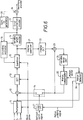
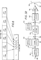
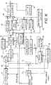
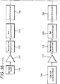
- FIGURE 32 is a block diagram showing one aspect of the seond embodiment at the encoding section of the transmission apparatus according to the present invention.
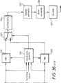
- FIGURE 33 is a block diagram showing another aspect of the second embodiment at the decoding section of the present invention.
- the component parts identical to those in FIGURE 11 are assigned with the same letters or symbols. These aspects of the embodiment are applied to a recording/playback apparatus.
- receiving video signals input through the transmission line 180 are input to the receiving demodulator 181.
- the receiving video signals are transmitted sequentially in the unit of frame, each frame is divided into such small blocks as 8 pixels in the horizontal direction x 8 pixels in the vertical direction and a top flag is added to the top of the frame. Further, each block data is encoded by DCT process, etc.
- the receiving demodulator 181 demodulates receiving video signals and provides them to the format converter 182 and the address generator 183.
- the multiplexer 184 multiplexes the outputs from these address generator 183 with the format converter 182.
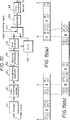
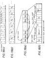
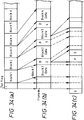
- FIGURES 34(a) through 34(c) are diagrams for illustrating the format converter 182, the address generator 183, the multiplexer 184 and the error correction encoder 162.
- Image data for one frame from the transmission line 180 is affixed with a top flag showing the top of the frame as illustrated in FIGURE 34(a) and thereafter, the image data consists of multiple block data of block 1, 2, .
- the address generator 183 assigns a series of frame numbers or header to the top flag and generating such address data as Block (B) 1, 2, . to each block 1, 2, ...., then provides them to the multiplexer 184.
- the format converter 182 converts the receiving image data format so that address data is arranged at the top of each block data and provides it to the multiplexer 184.
- the multiplexer 184 adds address data to the top of each block data and provides a data stream illustrated in FIGURE 34(b) to the error correction encoder. Further, to improve data playback efficiency, the format converter 182 may change playback data sequence.
- the error correction encoder 162 adds a parity signal P fitted for recording to the output from the multiplexer 184 and provides it to the adder 163.
- the synchronization/ID generator 164 generates a synchronizing signal and an ID signal and provides them to the adder 163.
- the adder 163 outputs the output of the error correction encoder 162 with a synchronizing a signal S added. After all, from the adder 163, a data stream with the synchronizing signal S added to the top of frame number and the parity signal P and the synchronizing signal S added to the middle of the data stream as shown in FIGURE 34(c) is output.
- the output of the adder 163 is fed to the recording/modulator 165.
- the recording/modulator 165 modulates the output of the adder 163 to fit for recording and provides it to the recording amplifier 166.
- the recording amplifier 166 amplifies the modulated signal from the recording/modulator 165 and feeds it to the magnetic head 167 for recording on the magnetic tape 168.
- the data recorded on the magnetic tape 168 is played back by the magnetic head 167 as shown in FIGURE 33.
- the playback signals from the magnetic head 167 are supplied to the playback amplifier 169.
- the playback amplifier 169 amplifies the playback signals and feeds them to the waveform equalizer 170.
- the waveform equalizer 170 equalizes the waveforms of the playback signals to remove inter-code interference and enable to identify data and provides them to the synchronizer 171.
- the synchronizer 171 extracts signals and ID signals and gives playback data in the unit of synchronizing signal to the demodulator 172.
- the demodulator 172 demodulates playback data and feeds them to the error corrector 193.
- the error corrector 193 corrects errors of playback data and provides the playback data to the delay circuit 185 and at the same time, adds an error flag to data which could not be corrected. Further, the error corrector 193 generates an error flag and address data of the decoded data to the zero data reparation controller 186.
- the zero data generation controller 186 generates address data of a block having errors (error block) from the error flag and address data and provides them to the switches 187 and 188 and at the same time, controls the delay circuit 185. Further, if an address data error is indicated by an error flag, the zero data generation controller 186 generates address data by estimating address from address data before and after the address data.
- the output of the error flagged zero data generator 189 is supplied to the terminal "a" of the switch 187 and data length adjusting bit source 190 is supplied to the terminal "b".
- the error fragged zero data generator 189 generates and provides zero data with a flag (F) added to show that there is no redundant bit or data which is ignored in the course of decoding in the block unit.
- the data length adjusting bit source 190 is an adjusting bit to make a block having error and a block having no error continuous.
- the switch 187 selects the terminal "a” or "b” under the control of the output from the zero data generation controller 186 . and supplies this output to the terminal "b" of the switch 188.
- the output of the delay circuit 185 is supplied.
- the delay circuit 185 adjusts a timing with the output of the switch 187 by delaying the output of the error corrector 193 under the control of the zero generation controller 186.
- the switch 188 selects the terminal "a” or "b” under the control of the zero data generator 186 and directly outputs the output of the delay circuit 185 for a block having no error, while outputs the output of the switch 187 in place of the output of the delay circuit 185 for a block having error.
- FIGURE 35(a) shows composite date for one scanning of the head in the playback operation at triple speed
- FIGURE 35(b) shows the output of the switch 188
- FIGURE 35(c) shows the output of the error flagged zero data generator 189.
- the portion between G1,K1' and G2,k2' and the portion between G2, k3' and G3, k4' shown by the broken line respectively show data not able to restore, unusable data because of many errors contained or unusable data because no synchronizing signal is played back.
- the receiving demodulator 181 demodulates data input through the transmission line 180 and provides the demodulated data to the format converter 182 and the address generator 183.
- Received data is added with a frame number at the top of frame data by the format converter 182, the address generator 183 and the multiplexer 184 and is also added with address data for each block and supplied to the error correction encoder 162.
- the received data is added with a parity signal P by the error correction encoder 162 and furthermore, added with a synchronizing signal S and ID signal by the adder 163 and supplied to the recording/modulator 165.
- the recording/modulator 165 modulates the output from the adder 163 to fit for recording and feeds it to the magnetic head 167 through the recording amplifier 166 for recording on the magnetic tape 168.
- playback data illustrated in FIGURE 35(a) is obtained from the magnetic head 167 when played back at triple speed.
- This playback data is supplied to the waveform equalizer 170 for waveform equalization through the playback amplifier 169, synchronizing signals are detected by the synchronizer 171 and demodulated in the unit of synchronizing signal in the demodulator 172.
- the demodulated output is supplied to the delay circuit 185 after the error correction in the error corrector 193.
- the error corrector 183 adds an error flag to the portion shown by the broken line in FIGURE 35(a), that is, the block G1, (k1 + 1)' through G2, (k2 + 1)' and the block G2, (k3 + 1)' through G3, (k4 + 1)' and provides these address data to the zero data generation controller 186.
- the zero data generation controller 186 decides delay amount of the delay circuit 185 from the error flag and address data and at the same time, controls the switches 187 and 188.
- the switch 187 provides zero data for each block (FIGURE 35(c)) from the error flagged zero data generator 189 to the terminal "b" of the switch 188 at a timing of an error block and then, provides a data length adjusting bit to the terminal "b" of the switch 188 for making this zero data and a block having no error continuous.
- the output of the delay circuit 185 is supplied to the terminal "a" of the switch 188.
- the switch 188 selects the terminal "a” or "b” under the control f the zero data generation controller 186.
- the switch 188 selects the delay circuit 185 for the period corresponding to the blocks G1, K0' through G2, K1' illustrated in FIGURE 35(a) and outputs the demodulated output of playback data directly, while selects the output of the switch 187 for the period corresponding to the blocks G1, k1' through G2, k2' and outputs the error flagged zero data blocks Ge, (K1 + 1) through G2, (k2 - 1)' and furthermore, outputs a date length adjusting bit (oblique lined section) for adjusting recording data by making this zero data block and block G2, K2' continuous.
- the switch 188 selects the output of the delay circuit 185 for the period corresponding to the blocks G2, K2' through G2, k3'. Then the switch 188, selecting the terminal "b", outputs the zero data blocks G2, (K3 + 1)' through G3, (K4 - 1)'' and a data length adjusting bit shown by the oblique line. The switch 188 then selects the output of the delay circuit 185 for the period corresponding to the next blocks G3, K4' through G4, K5'. Thus, error flagged zero data is inserted into the unplayed back portions shown by the broken line in FIGURE 35(a) and continuous sequential data are output from the switch 188.
- FIGURE 36 is a diagram showing the construction of a first aspect of the third embodiment according to the present invention.
- signals played back by a playback head 210 are, after amplified in an amplifier 211, subject to waveform equalization in a waveform equalizer 212 and are supplied to a bit synchronizer 213.
- the supplied signals are converted into digital data and after detection of synchronizing signal of each block in a synchronizer 214, the converted digital data are processed for time base correction in a TBC (Time Base Correction) circuit 215 and supplied to a switch 223.
- TBC Time Base Correction
- signals played back by a special purpose head 216 are, after amplified in an amplifier 217, processed for waveform equalization in a waveform equalizer 218 and supplied to a bit synchronizer 219.
- the supplied signals are converted into digital data and after detection of synchronizing signal of each block in a synchronizer 220, the converted digital data are processed for time base correction in a TBC circuit 221 and supplied to the switch 223.
- the digital data described above are variable length compression encoded data, consisting of synchronizing signal, ID signal, data and parity signal, and the synchronizing signal through the parity signal are made as one block; that is, valid data in the block unit.
- Outputs from the synchronizers 214 and 220 are also supplied to a valid data detector 222.
- a switching signal is also supplied to the valid data detector 222.
- This valid data detector 222 generates a control signal based on the switching signal and the outputs from the synchronizers 214 and 220, which sets a signal switching point and controls the switch 223 in such a special playback mode as in triple speed playback mode.
- the valid data detector 222 generates a time base correction signal to the TBC circuits 215 and 221. Based on this signal, the TBC circuits 215 and 221 synchronize signals.
- the data selected by the switch 223 are demodulated in the demodulator 224 and header information is extracted in a header extractor 225 and thereafter, the error correction is executed in an error corrector 226 and the data decoded to video signal in a demodulator 227.
- FIGURE 37 is a timing chart for illustrating the operation of the above embodiment.
- the synchronizing data (n1, n2, n3, Vietnamese) of the signals played back by the playback heads 210 are not synchronized with the synchronizing data (m0, m1, m2, 7-8) of the signals played back by the special purpose heads 216. If the switching signal is at "HIGH” level, synchronizing data and data Dm at the special purpose head are selected, while if the switching signal is at "LOW” level, the synchronizing data and data Dn at the playback head are selected. It is now assumed that the switching signal is switched from "LOW" to "HIGH” level at the X point under this condition.
- the switching signal is a signal which is obtained from the result of comparison of signal amplitudes likewise the conventional apparatus.
- the synchronizing data at the playback head are valid up to the X point, while the synchronizing data at the special purpose head are valid from data coming next to the X point.
- output synchronizing data will be n1, n2, m2, m3, .
- output data will be Dn1, Dn2, Dm2, Dm3, . and data Dn2 which was invalid so far will become valid.
- a playback head 210 through a TBC circuit 215 and a special purpose head 216 through a TBC circuit 221 are identical to those in the first embodiment and therefore, the explanation is omitted.
- the output signal of the TBC circuit 215 is demodulated in 4 demodulator 230 and is supplied to a header extractor 231.
- a header extractor 231 such header information relative to such data as address data length is extracted and is supplied to a valid data detector 222.
- the output signal of the TBC circuit 221 is demodulated in a demodulator 234 and supplied to a header extractor 235.
- the header information extracted in the header extractor 235 is supplied to the valid data detector 222.
- the output data of the header extractors 231 and 235 are supplied to buffers 233 and 237, respectively.
- the switching signal is also supplied to the valid data detector 222 where a decision logic is executed to set a switching point based on the supplied signal in this detector 222 and a control signal to control a switch 223 and that to control the buffers 233 and 237, respectively are output from this detector 222.
- playback operation of data is controlled by the control signal and both playback data are supplied to the switch 223.
- one of the playback data is selected by the control signal described above and is supplied to an error corrector 232.
- error corrected data is supplied to a decoder 228, where original image data is played back by decoding variable length data.
- FIGURE 39 is a timing chart for illustrating the operation of the above aspect of the embodiment.
- data is delimited by the unit of encoded data length not by a synchronizing signal.
- the data to be supplied from the playback head to the buffer 233 is assumed to be Dai (i is an integer) and the data to be supplied from the special purpose head to the buffer 237 is assumed to be Dbi. Further, if it is assumed that the switching signal was switched at the Y point, output data will contain data Da2 and Db2 at the Y point. That is, the output data will be Da1, Da2, Db2, Db3 . Thus, data at the switching point are prevented from becoming invalid.
- FIGURE 40 a third aspect of the third embodiment according to the present invention will be described in reference to FIGURE 40.
- the construction up to the header extractors 231 and 235 are identical to that in the second aspect of the embodiment and therefore, the explanation thereof will be omitted.
- the outputs from the header extractors 231 and 235 are supplied to error correctors 232 and 236, respectively and the error correction is executed if possible and an error detection flag is added if the error correction is not possible, and the outputs are supplied to the buffers 233 and 237.
- This error detection flag is also supplied to the valid data detector 222.
- the buffers 233 and 237 are controlled by the control signal which is the output of the valid data detector 222 and their outputs are both supplied to the switch 223. In the switch 223, one of the two supplied signals is selected by the control signal which is the output of the valid data detector 222 and is supplied to the decoder 228. In this decoder 228, original image data are obtained by decoding variable length data.
- FIGURE 41 is a timing chart for illustrating the operation in the third embodiment.
- the data switching is carried out according to presence of error in encoded data length unit, and the switching signal and synchronizing signal are not especially concerned with the data switching.
- the data Da5 and Da6 out of the data Da from the playback head have certain errors which could not be corrected.
- the error detection flag is added, the error detection signal will become "HIGH" level, likewise, the data Db1 and Db2 out of the data Db from the special purpose head have certain errors which could not be corrected. Therefore, output data consists of connected data excepting these portions of which errors could not be corrected. To be concrete, they are Da1, Da2, Da3, Da4, Db3, Db5 .... Thus, all of valid data are played back.
- the present invention is not limited to the above embodiments, and for instance, the number of divisions of the intra-frame compression processed frame can be set as desired.
- the present invention can provide such an effect in which a special playback stabilized picture quality can be obtained even when intra-frame compression data and inter-frame compression data are present, because intra-frame compression data can be recorded uniformly on a recording medium according to the present invention.
- the present invention can also provide such an effect in which zero data with an error flag added is output in place of an error block and an effect to improve image playback efficiency.
- the present invention can also provide such an effect to eliminate data which may become invalid, by switching signals based on synchronizing data unit, encoded data length unit and error detection signal in addition to a switching signal or by delaying one of data and connecting it to other data.
- thee present invention can provide an extremely preferable digital signal recording/playback apparatus.
Abstract
Furthermore, a device for setting an error flag in case of non-correctable errors is included, which generates zero data to replace erroneous encoded data.
A second set of special video heads is provided for a variable speed replay. According to the error rate, either the signal derived from the ordinary heads or the signal from the special heads is processed by the decoder.
Description
- The present invention relates generally to a digital signal recording/playback apparatus, and more particularly, to a variable length code recording in the digital signal recording/playback apparatus.
- A digital precessing of video data has been greatly developed in recent years. In particular, various systems for recording digital video data using a recording medium such as magnetic video cassette recorders (VCRs) have been developed. FIGURES 1(a) and 1(b) illustrate diagrams for explaining relations of the positions on a screen and the positions on the recording tracks of a recording medium in VCRs. FIGURE 1(a) indicates the positions on the screen and FIGURE 1(b) indicates the positions on the recording tracks.
- FIGURE 1(a) illustrates one frame of picture vertically divided into eight sections. FIGURE 1(b) indicates the record positions of the first through ninth tracks similarly divided into eight tracks. Video data are recorded in order on a recording medium starting from the lowest line position A of the first track to its top line position I, For instance, when recording one frame data on one track, data displayed in a horizontal section defined by lines a and b on a screen are recorded on a longitudinal section defined by lines A and B on a recording medium, and thereafter, in the similar manner data displayed in horizontal sections defined by lines b through i on the screen are recorded in the order on longitudinal sections defined by lines B through I on the recording medium. Further, for instance, when recording one frame data on two tracks, data in the horizontal section defined by the lines a and e on the screen are recorded on the longitudinal section defined by the lines A and I of the
first track # 1, while data in the horizontal section defined by the lines e and i on the screen are recorded on the longitudinal section defined by the lines E and I of thesecond track # 2. - FIGURES 2(a) through 2(d) are diagrams for illustrating the relationship between trace patterns and playback signal envelopes in data recording at a triple speed. FIGURE 2(a) illustrates trace patterns when playback data at triple speed with a head scanning time shown at the axis of abscissas and track pitch or tape traveling distance at the axis of coordinates. The signs "+" and "-" in the diagram indicate differentially oriented normal azimuths of the playback head, respectively. Further, numerals in the diagram show track numbers; thus odd number tracks are in the plus azimuth and even number tracks are in the minus azimuth. FIGURES 2(b) through 2(d) indicate the signal envelope played back by the ordinary head, the playback envelope by the special purpose head and the synthetic playback envelope obtained by both heads. FIGURE 3 is a diagram for illustrating the construction of the recording/playback heads.
- Now assumed that a
rotary cylinder 3, as shown in FIGURE 3, is used for the data recording and playback operations. Therotary cylinder 3 is equipped with a pair ofregular heads special purpose heads regular head 1 and its adjacentspecial purpose head 2 are also differentiated each other. As shown by the sign "+" in FIGURE 2(a), the first track and the third track are traced by theregular head 1 of the plus azimuth in the initial scanning period (tracing period), and the fourth track and the sixth track are traced by theregular head 1 of the minus azimuth in the next scanning period. Thus, the playback signal envelope shown in FIGURE 2(b) is obtained by theregular head 1. Further, the second track is traced by thespecial purpose head 2 in the initial scanning period and the playback signal envelope shown in FIGURE 2(c) is obtained in the same manner. By combining the playback output from theregular head 1 with the playback output from thespecial purpose head 2, the synthetic playback envelope shown in FIGURE 2(d) is obtained. - Table 1 shown below indicates relations among the playback outputs at the triple speed playback operation (FIGURE 2(d)), the traces of head and the corresponding positions on the screen.
Table 1 Playback Track 1 Frame/1 Track 1 Frame/2 Tracks Track Frame Track Frame # 1 1st Frame # 1 1st Frame 1 (A) - (C) (a) - (c) (A) - (C) (a) - (c) #2 2nd Frame # 2 1st Frame 2 (C) - (G) (c) - (g) (C) - (G) (f) - (h) #3 3rd Frame # 3 2nd Frame 3 (G) - (I) (g) - (i) (G) - (I) (d) - (e) #4 4th Frame # 4 2nd Frame 4 (A) - (C) (a) - (c) (A) - (C) (e) - (f) #5 5th Frame # 5 3rd Frame 5 (C) - (G) (c) - (g) (C) - (G) (b) - (d) #6 6th Frame # 6 3rd Frame 6 (G) - (I) (g) - (i) (G) - (I) (h) - (j) #7 7th Frame # 7 4th Frame 7 (A) - (C) (a) - (c) (A) - (C) (a) - (b) #8 8th Frame # 8 4th Frame 8 (C) - (G) (c) - (g) (C) - (G) (f) - (h) #9 9th Frame # 9 5th Frame 9 (G) - (I) (g) - (i) (G) - (I) (a) - (b) - As shown in FIGURE 2(d) and Table 1, data A through C on the
first track # 1 are played back by theregular head 1 in the first quarter (1/4) time interval in the initial scanning period, data of C through G on thesecond track # 2 are played back by thespecial purpose head 2 in the next half (1/2) time interval, and data of G through I on the third track are played back by theregular head 1 in the next 1/4 time interval. Thereafter, data on three tracks are played back in the similar manner in one scanning period. - When one frame video data are recorded on one track, the positions of A through C on the
first track # 1 correspond to the positions a through c on the first frame of image, the positions C through G on thesecond track # 2 correspond to the positions c through g on the second frame of the frame, and the positions G through 1 on thethird track # 3 correspond to the positions g through i on the third frame of the image, as shown in Table 1. Therefore, in the playback operation at a triple speed, the picture patterns at the positions on the first through the third frames are combined and displayed as a playback picture. - Further, when one frame video data are recorded on two tracks, the positions A through C on the
first track # 1 correspond to the positions a and b on the first frame, the positions C through G on thesecond track # 2 correspond to the positions f through h on the first frame, and the positions G through I on thethird track # 3 correspond to the positions d through e on the second frame as shown in Table 1. Further, the positions A through C on thefourth track # 4 correspond to the positions e and f on the second frame, the positions C through G on thefifth track # 5 correspond to the positions b through d on the third frame, and the positions G through I on thesixth track # 6 correspond to the positions h through i on the third frame. In this case, therefore, the picture patterns at the positions on the first through the third frames are presented in mix on the playback picture as shown in FIGURE 4(b). - By the way, various proposals have been proposed in recent years for the standardization of high efficient encoding for compressing video data. The high efficient encoding technique is to encode video data at more lower bit rate for improving efficiency of digital transmission and recording. For instance, the CCITT (Cometi Consultafif international Telegraphique et Telephonique (International Telegraph and Telephone Consultative Committee)) has issued a recommendation for video-conference/video-telephone standardization H. 261. According to the CCITT recommendation, the encoding is made by using the frame I processed an intra-frame compression and the frame P processed an inter-frame compression (or a predictive frame compression).
- FIGURE 5 is a diagram for explaining the video data compression according to the CCITT recommendation.
- The frame I processed intra-frame compression is the one frame video data encoded by the DCT (Digital Cosine Transformation) processing. The inter-frame Compression processed frame P is the video data encoded by the predictive encoding method using the intra-frame compression processed frame I or the inter-frame compression processed frame P. In addition, more lowering of bit rate has been made by encoding these encoded data to the data encoded in variable length. As the intra-frame compression processed frame I was encoded by the intra-frame information only, it is possible to decode it by a single encoded data only. However, the inter-frame compression processed frame P was encoded using the correlation with other video data, it cannot be decoded by a single encoded data only.
- FIGURE 6 is a block diagram for illustrating the recording section of a conventional apparatus for recording/playback variable length codes using such the predictive encoding.
- A luminance signal Y and color difference signals Cr and Cb are applied to a
multiplexer 11, where they are multiplexed in a block of 8 pixels x 8 horizontal scanning lines. Sampling rate of the color difference signals Cr and Cb in the horizontal direction is a half (1/2) of the luminance signal Y. Therefore, in the period when two 8 x 8 luminance blocks are sampled, one 8 x 8 block of the color difference signals Cr and Cb is sampled. As shown in FIGURES 7(a) through 7(c), two luminance signal blocks Y1 and Y2 and each of the color difference signal blocks Cr and Cb total, thus four blocks in total forms a macro block. Here, two luminance signal blocks Y1 and Y2 and each of the color difference blocks Cr and Cb represent the same position of the picture frame. The output of themultiplexer 11 is applied to a DCT (Digital Cosine Transformation)circuit 13 through asubtracter 12. - When performing the intra-frame compression, a
switch 14 is kept OFF and the output of themultiplexer 11 is applied directly to theDCT circuit 13 as described later. A signal composed of 8 x 8 pixels per block is applied to theDCT circuit 13. TheDCT circuit 13 converts the input signal into frequency components by the 8 x 8 two dimensional DCT processing This makes it possible to reduce the spatial correlative components. That is, the output of theDCT circuit 13 is applied to aquantizer 15 which lowers one block signal redundancy by requantizing the DCT output using a fixed quantization coefficient. Further, block pulses are supplied to themultiplexer 11, theDCT circuit 13, thequantizer 15, etc. which operate in block unit. - The quantized data from the
quantizer 15 is applied to avariable length encoder 16 and is, for instance encoded to the Huffman codes based on the result calculated from the statistical encoding amount of the quantized output. As a result, a short bit is assigned to data having a high appearance probability and a long bit to data having a low appearance probability and thus, transmission amount is further reduced. The output of thevariable length encoder 16 is applied to anerror correction encoder 17, which provides the output from thevariable length encoder 16 with an error correction parity added to amultiplexer 19. - The output of the
variable length encoder 16 is also applied to anencoding controller 18. The amount of the output data varies largely depending on input picture. So, theencoding controller 18 monitors the amount of the output data from thevariable length encoder 16 end regulates the amount of the output data by controlling the quantization coefficient of thequantizer 15. Further, theencoding controller 18 may restrict the amount of the output data by controlling thevariable length encoder 16. - A sync/
ID generator 20 generates frame a sync signal and ID signal showing data contents and additional information and provides them to themultiplexer 19. Themultiplexer 19forms 1 sync block data with a sync signal, ID signal, compressed signal data and parity and provides this data to the recoding/encoder which is not shown the recording/encoder, after recording/encoding the output from themultiplexer 19 according to characteristic of a recording medium, records the encoded data on a recording medium (not shown). - If the
switch 14 is ON, the current frame signal from themultiplexer 11 is subtracted from the motion compensated preceding frame, data which will be described later, in thesubtracter 12 and applied to theDCT circuit 13. That is, in this case the inter-frame encoding is carried out to encode differential data using redundancy of inter-frame picture. When a difference between the preceding frame and the current frame is simply obtained in the inter-frame encoding, it will become large if there is any motion in the picture. So, a differential value is made small by compensating the motion by obtaining a difference at the pixel position corresponding to the motion vector while detecting the motion vector by obtaining the position of the preceding frame corresponding to the fixed position of the current frame. - That is, the output of the
quantizer 15 is also applied to aninverse quantizer 21. This quantized output is inverse-quantized in theinverse quantizer 21 and further, inverse DCT processed in aninverse DCT circuit 22 and restored to the original video signal. Further, the original information cannot be played back completely in the DCT processing, requantization, inverse quantization and inverse DCT processing and part of the information lacks. In this case, as the output of the subtracter is a differential information, the output of theinverse DCT circuit 22 is also a differential information. The output of theinverse DCT circuit 22 is applied to anadder 23. This output from theadder 23 is fed back through avariable delay circuit 24 which delays signal by about one frame period and amotion compensator 25, and theadder 23 restores the current frame data by adding differential data to the preceding frame data and provides them to thevariable delay circuit 24. - The preceding frame data from the
variable delay circuit 24 and the current frame data from themultiplexer 11 are applied to amotion detector 26 where motion vector is detected. Themotion detector 26 obtains motion vector through the full search motion detection by, for instance, a matching calculation. In the full search type motion detection, the current frame is divided into the fixed number of blocks and the search range of, for instance, 15 horizontal pixels x 8 vertical pixels are set for each block. In the search range corresponding to the preceding frame, the matching calculation is carried out for each block and an inter-pattern approximation is calculated. Then, by calculating the preceding frame block which provides the minimum distortion in the search range, the vector which is obtained by this block and the current frame block is detected as the motion vector. Themotion detector 26 provides the motion vector thus obtained to themotion compensator 25. - The
motion compensator 25 extracts a corresponding block data from thevariable delay circuit 24, corrects it according to the motion vector and provides it to thesubtracter 12 through theswitch 14 and also, to theadder 23 after making the time adjustment. Thus, the motion compensated preceding frame data is supplied from themotion compensator 25 to thesubtracter 12 through theswitch 14 and when theswitch 14 is ON, the inter-frame compression mode results and if theswitch 14 is OFF, the intra-frame compression mode results. - The
switch 14 is turned ON/OFF based on a motion judging signal. That is, themotion detector 26 generates the motion judging signal depending on whether the motion vector size is in excess of a fixed threshold value and outputs it to alogic circuit 27. Thelogic circuit 27 controls the ON/OFF of theswitch 17 by the logical judgment using the motion judging signal and a refresh periodic signal. The refresh periodic signal is a signal showing the intra-frame compression processed frame I illustrated in FIGURE 5. If the input of the intra-frame compression processed frame I is indicated by the refresh periodic signal, thelogic circuit 27 turns theswitch 14 OFF irrespective of the motion judging signal. Further, if the motion judging signal indicates that the motion is relatively fast and the minimum distortion by the matching calculation exceeds the threshold value, thelogic circuit 27 turns theswitch 14 OFF and the intra-frame encoding is carried out for each block even when the inter-frame compression processed frame P data are input. Table 2 shown below indicates the ON/OFF control of theswitch 14 by thelogic circuit 27.Table 2 Frame I Intra-Frame Compression Switch 14 OFF Processed Frame Frame P Motion Vector Detected Switch 14 ONInter-Frame Compression Processed Frame Motion Vector Unknown Switch 14 OFF Inter-Frame Compression Processed Frame - FIGURE 8 is a diagram for illustrating the data stream of record signals which are output from the
multiplexer 19. - As shown in FIGURE 8, the first and the sixth frames of the input video signal are converted to the intra-frames I1 and I6, respectively and the second through the fifth frames are converted to the inter-frame compression processed frames P1 through P5. The ratio of data amount between the intra-frame compression processed frame I and the inter-frame compression processed frame P is (3 - 10) : 1. The amount of data of the intra-frame compression processed frame I is relatively much while the amount of data of the inter-frame compression processed frame P is extremely reduced. Further, the data of the inter-frame compression processed frame P cannot be decoded unless other frame data are decoded.
- FIGURE 9 is a block diagram indicating the decoding section (playback section) of a conventional variable length code recorder.
- Compressed encoded data recorded on a recording medium is played back by the playback head which is not shown and applied into an
error correction decoder 31. Theerror correction decoder 31 corrects errors produced in data transmission and recording. The playback data from theerror correction decoder 31 are applied to a variablelength data decoder 33 through acode buffer memory 32 and decoded to fixed length data. Further, thecode buffer memory 32 may be omitted. - The output from the
variable length decoder 33 is inverse quantized in aninverse quantizer 34, inverse DCT processed and decoded to the original video signal in aninverse DCT circuit 35, and applied to the terminal a of aswitch 36. The output of thevariable length decoder 33 is also applied to aheader signal extractor 37. Theheader signal extractor 37 retrieves a header showing whether the input data is the intra-frame compression data or the inter-frame compression data and provides it to theswitch 36. When supplied with a header shown the intra-frame compression data, theswitch 36 selects the terminal a and outputs decoded data from theinverse DCT circuit 35. - The inter-frame compression data is obtained by adding the output from the
inverse DCT circuit 35 and the preceding frame output from thepredictive decoder 39 using anadder 38. That is, the output of thevariable length decoder 33 is applied to amotion vector extractor 40 and the motion vector is thus obtained this motion vector is applied to apredictive decoder 39. The decoded output from theswitch 36 is delayed for one frame period by aframe memory 41. Thepredictive decoder 39 compensates the preceding frame decoded data from theframe memory 41 according to the motion vector and provides them to theadder 38. Theadder 38 decodes the inter-frame compression data by adding the output from thepredictive decoder 39 and the output from theinverse DCT circuit 35 and provides the decoded inter-frame compression data to the terminal b of theswitch 36. When the inter-frame compression data is applied, theswitch 36 selects the terminal b by the header and outputs the decoded data from theadder 38. Thus, the compression and expansion are carried out without delay. - However, the intra-frame compression processed frame I and the inter-frame compression processed frame P differ in encoded amount and if the data stream shown in FIGURE 8 is recorded on a recording medium, one frame is not necessarily able to play back by the playback data in the playback operation at a triple speed. Further, the inter-frame compression processed frame P processed inter-frame compression will become not able to playback if any undecoded frame is generated as in the playback operation at a triple speed because it cannot be decoded for an independent frame.
- Thus, the conventional variable length code recorder described above has such a problem of that the picture quality of a picture played back in the special playback operation deteriorates extremely because each frame data is in variable length and some frame data of a single frame only cannot be decoded.
- Since data of every frame is in variable length and there are frame data which cannot be decoded only by a single frame as described above, picture quality is deteriorated extremely in special playback operation. However, even in this case it s possible on a VCR which adopted a high efficiency encoding process to play back encoded data to some extent while suppressing error propagation by synchronizing signal, etc. However, if there are data which are not transmitted in such cases as video-conference, video-telephone, etc. where high efficiency encoded signals are applied to, for instance, TV set, errors are extensively propagated relatively and quality of displayed images is extremely deteriorated.
- This problem will be described in reference to FIGURE 10, FIGURE 11 and FIGURES 12((a) through 12(f). FIGURE 10 is a diagram for explaining a broadcasting system adopted for video-conference, video-telephone, etc.
- In a broadcasting station, video signals from cameras (not shown) are high efficiency encoded in an
encoder 151 and added with an error correction code in anerror correction encoder 152 corresponding to atransmission line 154. Atransmission modulator 153 modulates the output from theerror correction encoder 152 corresponding to thetransmission line 154 and then, provides it to thetransmission line 154 after converting into electric waves. At the receiving section, signals being applied through thetransmission line 154 are demodulated in a receivingdemodulator 155. Anerror corrector 156 corrects errors generated in thetransmission line 154 and feeds them to aswitch 157 and also to aVCR 158. TheVCR 158 records the input signals or plays back the signals and feeds them to theswitch 157. Theswitch 157 is switched by an input switching signal based on user operation and selecting the output of theerror corrector 156 or that of theVCR 158, provides it to adecoder 159. Thedecoder 159 decodes the high efficiency encoded signals to original signals and anerror corrector 160 corrects errors remaining in the decoded output without being corrected and provides them to a monitor TV set (not shown). Thus, the broadcasting signals applied through thetransmission line 154 or playback signals from theVCR 158 are displayed on the screen of the monitor TV set. - FIGURE 11 is a block diagram for illustrating the construction of a VCR which is capable of high efficiency encoding and decoding. Further, the VCR shown in FIGURE 10 is in the same construction as the right to the broken line in FIGURE 11.
- Video signals are high efficiency encoded in an encoder 161 and then applied to an
error correction encoder 162. Theerror correction encoder 162 provides the encoded data with an error correction parity code adapted to a VCR added to anadder 163. Theadder 163 adds a synchronizing signal and ID signal generated in anID generator 164 to the output of theerror correction encoder 162 and provides the output to a recording/modulator 165. The recording/modulator 165 modulates this output to adapt to the recording by a recording medium and provides it to arecording amplifier 166. Thisrecording amplifier 166 amplifies the modulated signals and feeds them to amagnetic head 167 for recording on atape 168. - In a playback operation of recorded signals, the
tape 168 is traced by themagnetic head 167 to play back recorded signals and the playback signals are supplied to aplayback amplifier 169. The playback signals from theplayback amplifier 169 are waveform equalized in awaveform equalizer 170 to reduce inter-code interference and then applied to asynchronizer 171. Thesynchronizer 171 restores the playback data in unit of recorded data train and feeds them to ademodulator 172. Thedemodulator 172 demodulates the playback data and feeds them to anerror corrector 173. Theerror corrector 173 corrects errors in the playback data and provides to adecoder 174. Thedecoder 174 and anerror corrector 175 are in the construction identical to those of thedecoder 159 and theerror corrector 160 shown in FIGURE 10, and decodes the output of theerror corrector 173 and after correcting errors, outputs the error corrected output. - Now, it is assumed that the
switch 157 shown in FIGURE 10 selects theVCR 158. Data transmitted from a broadcasting station via thetransmission line 154 are supplied to theVCR 158. Data transmitted from a broadcasting station via thetransmission line 154 are supplied to theerror corrector 156. Thus, the recording data train shown in FIGURE 12(a) is applied to theVCR 158. In this drawing, the subscript n denoted track number and the subscript m denotes recorded data train number. That is, Gn, m denote the mth data train on the nth track. - If the data train Gn,1 through Gn, m is recorded in the
VCR 158 and this data train is played back without error, the reencoded data train will become identical to the playback data train in the normal playback operation as shown in FIGURE 12(b). However, data is played back by the magnetic head while crossing the tracks in the playback operation at triple speed as described above and therefore, the playback data does not agree with the recorded data. That is, as shown in FIGURE 12(c), the k0 data train through the k1 data train are played back on the first track, the k2 through k3 data trains are played back on the second track, and the k4 through k5 data trains are played back on the third track. - The
VCR 158 carries out the demodulation, error correction and decoding processes of this playback data. However, as data decoding processes of this playback data. However, as data may not be played back correctly at such portions where the recording tracks are switched and furthermore, the playback data trains become discontinuous at switching points of the recording tracks, data around the track switching points cannot be used for decoding. Further, in theVCR 158, video data are recorded with a synchronizing signal and ID signal added and demodulated in unit of synchronizing signal in thesynchronizer 171 when played back and therefore, if data are not played back in the middle of a synchronizing block, it is possible to demodulate data from the start position of next synchronizing block. Thus, the portion shown by the broken line in FIGURE 12(d) of playback data by one scanning in the triple speed playback operation is not output against FIGURE 12(c). - However, even if header and address are added to data, a monitor TV set is not able to reconstruct images using these data and simply displays images in order of input image data As data trains being transmitted are variable length encoded data trains, even when data length of the broken lined part shown in FIGURE 12(d) is known, it is not possible to identify the start position of next data train k2's. Accordingly, it is not possible to display playback images using all playback outputs from the
VCR 158 on the screen of a monitor TV set and information data are not used effectively even when and error flag is added to them. That is, in such a system as video-telephone, which decodes input data trains continuously, if data are interrupted, subsequent data cannot be used efficiently. - So, in order to stop error propagation, decoding may be enabled for a fixed period of the top of a track by specifying the top of the track as the start position of a data train as shown in FIGURE 12(e). This will make it possible to decode a data train G1, KO' through G1, K1'. Further, FIGURE 12(f) illustrates an example where the data position with a Δ mark was set as the data train start position. In this case, the data train G1, 11 through G1, 12 can be decoded.
- As described above, there is also such a problem so far that if discontinuous data were transmitted, data available for effective use in playback operation of images decreases extremely.
- A playback signal processing method which is capable of special playback operation using the above special playback heads is shown in FIGURE 13. In this drawing, a signal played back by a
playback head 210 is amplified in anamplifier 211 and supplied to adetector 250 and aswitch 223. Similarly, a signal played back by aspecial purpose head 216 is amplified in anamplifier 17 and supplied to adetector 251 and theswitch 223. In thedetectors amplitude comparator 252. In theamplitude comparator 252, amplitudes of these two signals are compared and the result is supplied to aswitch 253. - A switching signal is also supplied to the
switch 253 and either one of these signals is selected by a mode selecting signal and supplied to theswitch 223 as a control signal. Theswitch 223 selects one of the outputs from theamplifiers demodulator 224 where the output signal is demodulated. This demodulated signal is restored to the original image signal in aplayback processor 254. - The switching signal described above is used to select a preset head output signal and if this signal is selected by the
switch 253, the outputs from theamplifiers amplitude comparator 252, a signal in larger amplitude normally selected. Therefore, if the output of theamplitude comparator 252 is selected by the mode selecting signal in theswitch 253, the output in larger amplitude of those outputs from theamplifiers switch 223. - FIGURE 14 illustrates trace patterns in the playback operation at triple speed. In this drawing, although the tracks are aslant on a tape, the trace of the head is vertical to the traveling direction of a tape because of triple speed. Therefore, the trace of the head extends over the tracks b, c and d. However, because the azimuth angles of the tracks b and c differ from those of the tracks c and d, data on
Trace 1 is played back by selecting data played back, for instance, by the playback heads from S to A out ofTrace 1, by the special purpose heads from A to B and by the playback heads from B to E. - If analog signals are played back in this way, an image without noise bar is obtainable on a screen. However, as data are recorded on a tape in block unit when they are digitally processed, if signals played back from two heads are switched according to the amplitude or at a preset switching point, the signals may be switched in the middle of a block. In this case, because data of the block makes no sense, invalid data was produced before or after the switching. This state is shown in FIGURES 15(a) and 15(b).
- FIGURE 15(a) indicates data played back by the playback head and FIGURE 15(B) is data played back by the special purpose head. "SY", "ID", "D" and "PA" indicate synchronizing signal, ID signal, data and parity signal, respestively. And, from "SY" through "PA" form one block.
- Here assuming that the switching points are set at the points A and B, signals are switched in the middle of data D. If the switching point is A, signals are synchronized as the positions of both "SY" are in accord with each other but data is invalid because the tracks are different. So, the portion of a in (a) and the portion of b in FIGURE 15(b) become invalid data. If the switching point is B, signals are not synchronized as both of two "SY" are out of position. As described above, if the switching point is preset or set according to the amplitude, invalid data was produced before and after the switching point and in addition, signals could not be synchronized is some cases.
- When a recorded video tape is played back in a VTR at triple speed, the trace of the head is made crossing three tracks on a magnetic tape. To prevent azimuth angles from becoming different or noise bars from being generated on a screen, special playback heads were provided adjacent to ordinary playback heads and recorded data were played back by switching signals played back by the respective playback heads. However, when recorded data were digitally processed, if the switching point was preset or set according to the signal amplitude, invalid data were produced before or after the switching point and furthermore, signals could not be synchronized in some cases.
- The present invention therefore seeks to provide an apparatus for recording/playback digital data with variable length codes which is capable of obtaining the stabilized quality of specially playback picture even when intra-frame compression data and inter-frame compression data are available.
- The present invention also seeks to provide an apparatus for recording/playback digital data with variable length codes which is capable of improving efficiency of image played back by transmitting encoded data with a virtual signal fitted for an image playback apparatus inserted into error portions.
- The present invention still also seeks to provide an apparatus for recording/playback digital data with variable length codes which is capable of improving quality of pictures when they are specially played back by making the most of data which were invalid so far.
- A digital signal recording/playback apparatus according to one aspect of a first embodiment of the present invention includes a data rearranging circuit for rearranging the intra-frame compression data in the variable length encoded data and an address and a data length adding circuit for adding addresses and data length information of the intra-frame compression data output from the data rearrangement circuit.
- In a second aspect of the apparatus for recording/playback digital data with variable length codes which are encoded from intra-frame compression data and inter-frame compression data according to the first embodiment of the present invention, the data rearranging circuit includes a circuit for rearranging the inter-frame compression data in the variable length encoded data in unit of a sync block of recorded codes.
- A third aspect of the apparatus for recording/playback digital data with variable length codes which are encoded from intra-frame compression data and inter-frame compression data according to the first embodiment of the present invention, includes a data rearranging circuit for uniformly rearranging all data by combining the intra-frame compression data and the inter-frame compression data into one frame data and varying the arrangement of the one frame data in the intra-frame compression data at a frame unit and a circuit for adding address information and data length information of the intra-frame compression data included in the data rearranging circuit.
- In a fourth aspect of the apparatus for recording/playback digital data with variable length codes which are encoded from intra-frame compression data and inter-frame compression data according to the first embodiment of the present invention, the data rearranging circuit includes a circuit for dividing the one frame data into a predetermined number of data sections which are comprised of the intra-frame compression data and the inter-frame compression data, and a circuit for uniformly arranging all of the intra-frame compression data by varying the arrangement of the intra-frame compression data in the each data section in frame unit.
- A fifth aspect of the apparatus for recording/playback digital data with variable length codes which are encoded from intra-frame compression data and inter-frame compression data according to a second embodiment of the present invention, includes an encoder having an address information generater for generating address information for each block of high efficiency encoded data and a multiplexer for multiplexing the address information onto the encoded data.
- A sixth aspect of the apparatus for recording/playback digital data with variable length codes which are encoded from intra-frame compression data and inter-frame compression data according to the second embodiment of the present invention, includes a decoder having an error detecting means for detecting errors in high efficiency encoded data comprising address information multiplexed on an encoded data for each block, a zero data generator for generating zero data in block unit with an error flag added, a switch for selectively outputing the encoded data or the output from the zero data generator, a controller for controlling the switch to replace a transmission data error block with an output from the zero data generator by detecting an error block address from the detected result of the error detector and an invalid data inserting circuit for inserting invalid data between the encoded data and the zero data in order to maintain an output data rate of the switch constant.
- A seventh aspect of the apparatus for recording/playback digital data with variable length codes which are encoded from intra-frame compression data and inter-frame compression data according to a third aspect of the present invention, includes at least two ordinary video heads provided on a rotating drum for ordinary playback operation, at least two special video heads provided adjacent to the ordinary video heads, respectively, for use only in special playback operation, a first playback processor for playing back compression encoded digital signals by the ordinary video heads, a second playback processor for playing back compression encoded digital signals by the special video heads, a generator for generating a control signal by obtaining a switching point where invalid data is least produced through a calculation based on outputs from the first and second playback processors a selector for selecting either one of the outputs of the first and second playback processing means based on the control signal, and a decoder for decoding video signals based on the output from the selector.
- For a better understanding of the present invention and many of the attendant advantages thereof, reference will now be made by way of example to the accompanying drawings, wherein:
- FIGURES 1(a) and 1(b) are diagrams for explaining the contrast of the positions on the frame with the positions on a recording medium in a conventional example;
- FIGURES 2(a) through 2(d) are diagrams for illustrating the relationship between the trace pattern and the playback envelop at triple speed playback;
- FIGURE 3 is a diagram for illustrating the construction of the recording/playback head;
- FIGURES 4(a) and 4(b) are diagrams for explaining the construction of the playback frame in a conventional example;
- FIGURE 5 is a diagram for explaining the compression method according to H. 261 recommendation;
- FIGURE 6 is a block diagram for illustrating the recording side of conventional variable length code recorder adopting the predictive encoding;
- FIGURE 7 is a diagram for explaining the macro block;
- FIGURE 8 is a diagram for illustrating the data stream of recorded signals in the recorder shown in FIGURE 6;
- FIGURE 9 is a block diagram for illustrating the decoding side (playback side) of a conventional variable length code recorder;
- FIGURE 10 is a block diagram for explaining the problem according to a conventional example;
- FIGURE 11 is a block diagram for explaining the problem according to a conventional example;
- FIGURES 12(a) through 12(f) are diagrams for explaining the problem according to a conventional example;
- FIGURE 13 is a block diagram for illustrating the conventional construction;
- FIGURE 14 is a diagram for explaining the relation between tracks and trace of the head;
- FIGURES 15(a) and 15(b) are diagrams for explaining the construction of compression encoded image data;
- FIGURE 16 is a block diagram for illustrating one embodiment of the recording section (encoding section) of the variable length code recorder according to the present invention;
- FIGURE 17 is a block diagram for illustrating one embodiment of the recording section (encoding section) of the variable length code recorder according to the present invention;
- FIGURES 18(a) through 18(f) are diagrams for explaining the principle of this embodiment;
- FIGURES 19(a) through 19(f) are diagrams for explaining the principle of this embodiment;
- FIGURES 20(a) through 20(c) are diagrams for explaining the principle of this embodiment;
- FIGURES 21(a) through 21(k) are diagrams for explaining the principle of this embodiment;
- FIGURES 22(a) through 22(e) are diagrams for illustrating the output frame in the embodiment.
- FIGURE 23 is a block diagram for illustrating another embodiment of the present invention;
- FIGURE 24 is a diagram for explaining the encoding in another embodiment of the present invention;
- FIGURES 25(a) through 25(e) are diagrams for illustrating FIGURE 24 by separating every one frame;
- FIGURES 26(a) through 26(c) are diagrams for explaining the data stream in the embodiment shown in FIGURE 24;
- FIGURES 27(a) through 27(c) are diagrams for explaining the encoding in another embodiment of the present invention;
- FIGURES 28(a) through 28(d) are diagrams for explaining the data stream in the embodiment shown in FIGURES 27(a) through 27(c);
- FIGURE 29 is a diagram for illustrating a contrast of FIGURES 28(a) through 28(d) with the frame picture;
- FIGURES 30(a) through 30(c) are diagrams for explaining the data format of another embodiment;
- FIGURES 31(a) through 31(c) are diagrams for explaining the data format of another embodiment;
- FIGURE 32 is a block diagram for illustrating an embodiment of the encoding section of the transmission apparatus of the present invention;
- FIGURE 33 is a block diagram for illustrating an embodiment of the decoding section of the transmission apparatus of the present invention;
- FIGURES 34(a) through 34(c) are diagrams for explaining the embodiment of FIGURE 32;
- FIGURES 35(a) through 33(c) are diagrams for explaining the operation of the transmission apparatus according to the embodiment of FIGURE 33;
- FIGURE 36 is a block diagram for illustrating the construction of the first embodiment of the present invention;
- FIGURE 37 is a timing chart for explaining the operation of the first embodiment of the present invention;
- FIGURE 38 is a block diagram for illustrating the construction of the second embodiment of the present invention;
- FIGURE 39 is a timing chart for explaining the operation of the second embodiment of the present invention;
- FIGURE 40 is a block diagram for illustrating the construction of the third embodiment of the present invention; and
- FIGURE 41 is a timing chart for explaining the operation of the third embodiment of the present invention.
- The present invention will be described in detail with reference to the FIGURES 16 through 41. Throughout the drawings, reference numerals or letters used in FIGURES 1 through 15 will be used to designate like or equivalent elements for simplicity of explanation.
- Referring now to FIGURES 16 through 31, a first aspect of the present invention will be explained in detail as possible. FIGURE 16 is a block diagram for illustrating an embodiment of the recording section (encoding section) of the variable length code recorder according to the present invention. FIGURE 17 is a block diagram for illustrating an embodiment of the playback section (decoding section) of the variable length code recorder of the present invention. In FIGURES 16 and 17, the same component parts as in the FIGURES 6 and 9 are assigned with the same sings. This embodiment is applied to a recorder which performs the intra-frame compression for each frame.
- First, the principle of this embodiment is explained in reference to FIGURES 18(a) through 18(f), FIGURES 19(a) through19(f) and FIGURES 20(a) through 20(c). FIGURE 18(a) indicates the division of the intra-frame area, FIGURE 18(b) indicates the arrangement of the intra-frame compression processed frame and the inter-frame compression processed frame, and FIGURES 18(c) through 18(f) indicate the data format of a recording signal.
- In this embodiment, as shown in FIGURE 18(a), the intra-frame compression processed frame I is divided into five parts horizontally or vertically and the divided parts are referred to as i1, i2, i3, i4 and i5, respectively. The intra-frame compression processed frame I is constructed for every six frames. That is, the frames are arranged in order of the intra-frame compression processed frame I1, inter-frame compression processed frames P1 through P5, intra-frame compression processed frame I7, ..... and so on. The intra-frame compression processed frame I is divided into five parts and five frames P are continued between the intra-frames I. Further, it is desirable that the number of divided parts of the intra-frame compression processed frame I and the number of continuous data of the inter-frame compression processed frame P are at a fixed ratio.
- When a series of these frame data is processed by intra-frame or inter-frame compression processes, the data stream after the compression is arranged in order of I1 (i1) (data corresponding to the part i1 of the intra-frame compression processed frame I), I1 (i2), ..... (I1 (i5), P2, P3, ..... and so on a as shown in FIGURE 18(c). Further, the time division of the data streams I1 (i1) through I) (i5) by processing in a time sequence may not be possible.
- In this embodiment, the data stream shown in FIGURE 18(c) is converted into the arrangement shown in FIGURE 18(d). That is, it is arranged in such combinations as Data I1 (i1) and Data P2, Data I1 (i2) and Data P3, Data I1 (i3) and Data P4, Data I1 (i4) and Data P5, Data I1 (i5) and Data P6, ..... and so on. In this case, the data combination is so set that the data rate becomes almost constant.
- The set of data consisting of the data of Part i of the intra-frame compression processed frame I and the data of the inter-frame compression processed frame P is composed of the plural number of sync blocks a shown in FIGURE 18(e). Further, the data of Part i of the intra-frame compression processed frame I is composed of m2 macro blocks. That is, one frame is composed of (5 x m2) pieces of macro block. In this embodiment, the number of sync block m1 that is recorded on one track of a recording medium is set to satisfy the following expression (1).

where k is a positive integer or a positive fraction. - For instance, in case of k = 1, a sync block corresponds to a macro block at 1 : 1 and in case of k = 2, one sync block corresponds to two macro blocks. Further, in case of k = 1/2, a macro block is divided into two to correspond to one sync block. For instance, a macro block may be divided to a set of the luminance signals Y1, Y2 and a set of the color difference signals Cb, Cr to correspond to a sync block. Further, a macro block may be divided to a set of the luminance signal Y1 and the color difference signal Cb and a set of the luminance signal Y2 and the color difference signal Cr to correspond to a sync block. Each macro block corresponds to a fixed sync block in this way.
- The macro block which is processed by the intra-frame compression process is added with such information as ID showing its number and address to compare its macro block with the frame position and macro block data length as shown in FIGURE 18(f). If these data do not satisfy one sync block length, a sync block is composed with the inter-frame compression processed frame P data added in order and an error correction parity added lastly.
- If data of macro blocks can be arranged in one sync block, there is no problem. If a macro block length is too long to arrange one macro block fully in one sync block, it is necessary to process excess data. The required process is, for instance, a method to add excess data to next macro block information, a method to delete excess data or a method to arrange the excess data in next macro block, slide subsequent macro blocks. In order and absorb the excess data within the number of synC blocks provided excessively in advance.
- As shown in FIGURES 18(d) through 18(f), the data of sections i1 through i5 of the intra-frame compression processed frame I1 is uniformly arranged at regular intervals and following the data in the
section 15, the data of the sections i1 through i5 of the intra-frame compression processed frame I7 is uniformly arranged. Thus, the data of the sections i1 through i5 of the intra-frame compression processed frames I1 and I7 is arranged at regular intervals in the unit of macro block. Further, each of the macro blocks is added with its address and data length to facilitate to clearly grasp a sync block corresponding to a fixed macro block. - When the data in this format is recorded on a magnetic tape, the intra-frame compression data is uniformly arranged on the recording track. FIGURES 19(a) through 19(f) are diagrams for explaining the tracing of the intra-frame compression processed frames in the playback operation at a triple speed. FIGURES 19(a) through 19(f) show the reproducing positions of the first to the sixth tracings by the oblique lines, respectively. In FIGURES 19(a) through 19(f), one frame data is recorded on one track, that is, it is assumed that the amount of data of one frame is equivalent to the amount of data of one track as an average. Further, similar to FIGURE 2(d), for instance, the played back synthetic playback envelope of the
tracks # 1, #2 and #3 is obtained in the first tracing. - As described above, the inter-frame compression data is for differential picture and cannot be output even when it is decoded by performing the inverse quantization process and the inverse DCT process unless the preceding frame data is played back. However, the intra-frame compression data can be directly used by decoding it. If the intra-frame compression data is uniformly arranged on the recording tracks and error rates of the playback section are above the tolerance, it is able to playback and a playback picture is predictable when the playback position is decided. If the tracing position is definite, a picture capable of playback can be grasped certainly.
- As shown in FIGURE 19(a), the
tracks # 1, #2 and #3 are traced in the first tracing and the data of the section i1 through i3 of the intra-frame compression processed frame I1 iq played back. In the second tracing, thetracks # 4, #5 and #6 are traced and the data of the section i4 and i5 of the intra-frame compression processed frame I1 and those of the section i5 of the intra-frame compression processed frame I7 is played back as shown in FIGURE 19(b). In the third tracing, thetracks # 7, #8 and #9 are traced and the data of the sections i2 through i4 of the intra-frame compression processed frame I7 is played back as shown in FIGURE 19(c). In the fourth tracing, thetracks # 10, #11 and #12 are traced and the data of the section i5 of the intra-frame compression processed frame I7 and the data of the sections i1 and i2 of the intra-frame compression processed frame I13 is played back as shown in FIGURE 19(d). In the fifth tracing, thetracks # 13, #14 and #15 are traced and the data of the sections i3 through i5 of the frame I13 is played back as shown in FIGURE 19(e). In the sixth tracing, the same parts as in the first tracing are traced, that is, the data of sections i1 through i3 of the intra-frame compression processed frame I19 is played back as shown in FIGURE 19(f). From the leastcommon multiple 15 of the number of division [5] of the intra-frame compression processed frame and the playback speed [3], it is seen that all data is played back by the tracing of 15 tracks. - FIGURES 20(a) through 20(c) are diagrams for illustrating the composition of a playback picture. FIGURE 20(a) shown the composition according to the tracing method shown in FIGURES 19(a) through 19(f) and FIGURES 20(b) and 20(c) shown the composition according to the tracing method in another embodiment described later.
- As shown in FIGURE 20(a), when the tracing method shown in FIGURES 19(a) through 19(f) is used, all sections of one frame picture are played back by the first through the fifth tracings and a picture is composed by the playback data of the sections of the intra-frame compression processed frames I1, I7 and I13.
- FIGURES 21(a) through 21(k) are diagrams for explaining the tracing of the intra-frame compression processed frame for recording one frame picture by dividing it to two tracks in the triple speed playback operation. FIGURES 21(a) through 21(k) illustrate the first through eleventh tracings, respectively. Further, FIGURES 22(a) through 22(e) are diagrams for illustrating an output frame picture.
- In this recording method, it may be considered that all sections of the intra-frame compression processed frame are divided into two upper and lower parts and record vertically in order from the left end. That is, in the first tracing, the upper 1/4 part at the upper portion of section il, the central 1/2 part at the lower portion of the section i1, and the lower 1/4 parts at the upper portion of the section i2 are played back as shown in FIGURE 21(a). In the second tracing, the upper 1/4 parts at the lower portion of the
section 12, the central 1/2 part at the upper portion of the section i3, and the lower 1/4 part at the lower portion of the section i3 are played back as shown in FIGURE 21(b). Thereafter, the tracings are repeated in the same manner and in the eleventh tracing, the same section as in the first tracing is played back as shown in FIGURE 21(k). - As one frame data is divided to be recorded on two tracks, one frame passes in two tracings. That is, the section to be updated for each frame in the playback operation is for two tracings and the section to be updated for five frames are as shown in FIGURES 22(a) through 22(e). As shown in FIGURES 21(a) through 21(k) and FIGURES 22(a) through 22(e), all sections of one frame are played back in 10 times tracings.
- Next, the construction of the recorder to realize the principle described in the above is explained.
- In FIGURE 16, a luminance signal Y and color difference signals Cr and Cb are applied to a
multiplexer 11. The multiplexer I1 multiplexes the input signals in unit of eight (8) pixels x eight (8) horizontal scanning lines per block and also, multiplexes them in unit of macro block consisting of two luminance signal blocks Y and each one color difference signal block Cr and Cb and provides them to asubtracter 12. Thesubtracter 12 is supplied with the proceeding frame data through aswitch 14, and subtracting the preceding frame data from the output from themultiplexer 11 at a time of the inter-frame compression process, provides the result to aDCT circuit 13, while provides the output from themultiplexer 11 directly to theDCT circuit 13 at a time of the intra-frame compression process. - The
DCT circuit 13 processes the output of thesubtracter 12 through the 8 x 8 two-dimensional DCT process and provides the result to aquantizer 15. The quantizing coefficient of thequantizer 15 is controlled by anencoding controller 18, which lowers a bit rate by quantizing the output of theDCT circuit 14 using the quantizing coefficient and provides it to avariable length encoder 50. Thevariable length encoder 50, under the control of theencoding controller 18, further lowers the bit rate by converting the input data to variable length codes and provides it to amultiplexer 51 and an inter-framecompression data memory 52. Further, thevariable length encoder 50 generates an MH signal for each macro block and provides it to an address generation and datalength measuring circuit 53. The encodingcontroller 18 changes the quantizing coefficient based on the output from thevariable length encoder 50 and at the same time, limits the total amount of codes by limiting the number of bits of the output of thevariable length encoder 50. Further, block pulses are supplied to themultiplexer 11, theDCT circuit 13, thequantizer 15, etc. which perform the processing in block unit. - The output of the
quantizer 15 is applied to aninverse quantizer 21. Thisinverse quantizer 21 provides the quantized output after inverse quantizing to aninverse DCT circuit 22. Theinverse DCT circuit 22 restores the output of theinverse quantizer 21 to the original data before DCT processing and provides the result to anadder 23. The output of theadder 23 is fed back through avariable delay circuit 24 which delays for one frame period and and then applies to amotion compensator 25, and theadder 23 restores the original data before the processing of differential data by thesubtracter 12 by adding the differential data of the current frame with the proceeding frame data and provides the restored data to thevariable delay circuit 24. The output of thevariable delay circuit 24 is also applied to amotion detector 26. - The
motion detector 26 is also supplied with the output from themultiplexer 11 and obtaining a motion vector by the matching calculation by, for instance, the full search motion vector detection, provides it to themotion compensator 25 and the same time, provides a motion judging signal, which is based on whether a distortion value by the matching calculation is in excess of a fixed threshold value, to amotion logic circuit 27. Themotion compensator 25 corrects the output of thevariable delay circuit 24 based on the motion vector and provides the motion corrected preceding frame data to thesubtracter 12 through theswitch 14. Themotion logic circuit 27 controls the ON/OFF of theswitch 14 based on the motion judging signal and a refresh periodic signal indicating the intra-frame compression processed frame. - In this embodiment, the refresh periodic signal is also applied to the address generation and data
length measuring circuit 53. Supplied with the refresh periodic signal indicating the intra-frame compression processed frame I and the MB signal, the address generation and datalength measuring circuit 53 generates address for every MB signal in the intra-frame compression processed frame I and measures data length between MB signals. Macro block address and data length contained in the data of the sections i1 through i5 of the frame I1, I7 and I13 obtained by the address generation and datalength measuring circuit 53 are applied to themultiplexer 51. - The
multiplexer 51 multiplexes macro block address and data length to the intra-frame compression data from thevariable length encoder 50 and provides the result to the intra-framecompression data memory 57. The intra-framecompression data memory 57 stores the intra-frame compression data from themultiplexer 51 and the intra-framecompression data memory 52 stores the inter-frame compression data from thevariable length encoder 50 and provides them to the multiplexer (hereinafter referred to as the MPX) 58. Thememory P controller 54 and thememory I controller 55 control the write to the inter-framecompression data memory 52 and the intra-framecompression data memory 57 based on the data from the address generation and datalength measuring circuit 53. The output of the address generation and datalength measuring circuit 53 is also applied to thedata rearrangement controller 56 which rearranges the data stream shown in FIGURE 18(c) by controlling thememory P controller 54, thememory 1controller 55 and theMPX 58. That is, theMPX 58, under the control of thedata rearrangement controller 56, multiplexes macro block address, data length, as shown in FIGURES 18(d) through 18(f), and intra-frame compression data for each sync block and multiplexing inter-frame compression data from the inter-framecompression data memory 52 to the remaining range of one sync block, provides the result to theerror correction encoder 17. Theerror correction encoder 17 provides this input with an error correction parity added to themultiplexer 19. The sync/ID generator 20 generates a sync signal and ID signal and provides them to themultiplexer 19. Themultiplexer 19 provides these sync signal and ID signals by adding to the output of theMPX 58. The output of themultiplexer 19 is recorded on a recording medium through the recording head which is not shown. - Next, the circuits in the decoding section will be explained in reference to FIGURE 17.
- The data played back from a recording medium by the playback head which is not shown is applied to a demultiplexer (hereinafter referred to as the DMPX) 62 and an address and
data length extractor 61 after the error correction in the error corrector (not shown). The address anddata length extractor 61 extracts address of a macro block and its data length added for each sync block to theDMPX 52 and aheader extractor 63. TheDMPX 62 is controlled based on a macro block data length and separating the input data to the intra-frame compression data and the inter-frame compression data and provides them tovariable length decoders variable length decoders header extractor 63 and at the same time, provide the decoded outputs to anintra-frame buffer 66 and aninter-frame buffer 67, respectively. - The
header extractor 63 receives the decoded intra-frame compression data, the decoded inter-frame compression data, address and data length of a macro block, and provides an indicating signal to restore the time sequence of the decoded data to an intra-frame compressiondata rearrangement canceller 68, amemory I controller 69 and amemory P controller 70. Thememory I controller 69 and thememory P controller 70 control the read/write of theintra-frame buffer 66 and theinter-frame buffer 67 based on the indicating signal and the outputs from the intra-frame compressiondata rearrangement canceller 68. The outputs from theintra-frame buffer 66 and theinter-frame buffer 67 are applied to anMPX 71, which in turn restores the input data to the original data stream shown in FIGURE 18(c) and provides it to theinverse quantizer 34 and themotion vector extractor 40. - The construction of the recorder composed of the
inverse quantizer 34 which inversely quantizes input signals, theinverse DCT circuit 35 which processes the inverse-DCT on the output of theinverse quantizer 34, theheader signal extractor 37 which extracts the header signal, themotion vector extractor 40 which extracts motion vector, theframe memory 41 which delays the output signal for one frame period, thepredictive decoder 39 which compensates the output of theframe memory 41 for motion, theadder 38 which decodes the inter-frame compression data by adding the output from theinverse DCT circuit 35 with the output from thepredictive decoder 39 and theswitch 36 which switches and provides the decoded intra-frame compression data and the decoded inter-frame compression data is the same as before. - Next, the operation of the embodiment constructed as described above is explained.
- The processes up to the
variable length encoder 50 at the recording section (see FIGURE 16) are the same as before. That is, the luminance signal Y and the color difference signals Cr and Cb are multiplexed in unit of 8 pixels x 8 horizontal scanning lines per block and further, multiplexed in the unit of macro block consisting of total four blocks of two luminance signal blocks Y and each one of color difference signal block Cr and Cr by themultiplexer 11 and applied to thesubtracter 12. When preparing intra-frame compression data, theswitch 14 is turned OFF, the output from themultiplexer 11 is DCT processed in theDCT circuit 13, quantized in thequantizer 15 and a bit rate is lowered. The quantized output is applied to thevariable length encoder 50 where is is encoded in variable length and is applied to themultiplexer 51. - The output of the
quantizer 15 is fed back to thesubtracter 12 after delayed for one frame period through theinverse quantizer 21, theinverse DCT circuit 2, thevariable delay circuit 24, themotion compensator 25 and theswitch 14 and when preparing inter-frame compression data, thesubtracter 12 subtracts the preceding frame data from the output of themultiplexer 11 and provides a difference to theDCT circuit 13. Data rate of this differential data is lowered by theDCT circuit 13 and thequantizer 15, converted into variable length codes and applied to the inter-framecompression data memory 52. - In this embodiment, the
variable length encoder 50 generates an MB signal for each macro block and provides it to the address generation and datalength measuring circuit 53. The address generation and datalength measuring circuit 53 is supplied with the refresh period signal indicating the intra-frame compression processed frame I, generates an address for every MH signal (for every macro block) in the intra-frame compression processed frame I and measures data length between MB signals (a data length of a macro block). - The
multiplexer 51 is supplied with addresses and data lengths from the address generation and datalength measuring circuit 53 and provides the macro blocks composing the sections i1 through i5 of the intra-frame compression processed frame with the addresses and data lengths (see FIGURE 18(f)) to the intra-framecompression data memory 57. The address generation and datalength measuring circuit 53 controls the memory P controller 94, thememory I controller 55 and thedata rearrangement controller 56, and thememory P controller 54 and thememory I controller 55 are further controlled by thedata rearrangement controller 56. As a result, the inter-framecompression data memory 52 and the intra-framecompression data memory 57 are controlled by thememory P controller 54 and thememory I controller 55, respectively for the data read/write, and provide the stored data to theMPX 58. Thedata rearrangement controller 56 also controls theMPX 58 and rearranging the data stream illustrated in FIGURE 18(c), provides it after converting into the array illustrated in FIGURE 18(d). - The output of the
MPX 58 is added with a parity for error correction by theerror correction encoder 17, added with a sync signal and ID in themultiplexer 19 and is converted to the data train as shown in the FIGURES 18(d) through 18(f). The output from themultiplexer 19 is recorded in a recording medium through the recording head which is not shown. - In this embodiment, as the intra-frame compression data is divided into five sections, each of which makes a set with inter-frame compression data and is uniformly arranged in the unit of sync block, intra-frame compression data is uniformly recorded on a recording medium.
- At the decoding section, the playback output from a recording medium which is not shown is applied to the address and
data length extractor 61 and theDMPX 62 illustrated in FIGURE 17 after correction errors, if any. As the intra-frame compression data was uniformly recorded on a recording medium, it is possible to play back all parts of the intra-frame compression data by restoring the number of frames based on the number of fractions of the intra-frame compression processed frame, the playback speed, and the number of tracks, on which one frame picture is recorded even when a special playback operation was carried out. - The address and
data length extractor 61 extracts the macro block address and data length added to each sync block. TheDMPX 62 is controlled based on a data length supplied from the address anddata length extractor 61 and separating the intra-frame compression data and the inter-frame compression data, provides them to thevariable length decoders variable length decoders intra-frame buffer 66 and theinter-frame buffer 67, respectively. - The decoded data from the
variable length decoders 64 and 75 is also applied to theheader extractor 63. Theheader extractor 63 is also supplied with the output from the address anddata length extractor 61 and preparing an indicating signal to restore a time sequence to the original data, provides it to thememory I controller 69, thememory P controller 70 and the intra-frame compressiondata rearrangement canceller 68. Theintra-data rearrangement canceller 68 controls thememory I controller 69, thememory P controller 70 and theMPX 71 based on the indicating signal and header information. As a result, thememory I controller 69 and thememory P controller 70 control read/write of theintra-frame buffer 66 and theinter-frame buffer 67 and provide the intra-frame compression data and inter-frame compression data converted to a fixed length to theMPX 71. TheMPX 71 is controlled by theintra-data rearrangement canceller 68 and outputs a data array illustrated in FIGURE 18(c), that is, a data array in which five frames of inter-frame compression data are continued between the intra-frame compression data is output. - The subsequent operations are the same as before. The decoded intra-frame compression data is applied to the terminal a of the
switch 36 by theinverse quantizer 34 and theinverse DCT circuit 35, and the decoded inter-frame compression data is applied to the terminal b of theswitch 36 from theadder 38 which adds the decoded preceding frame data from thepredictive decoder 39 with the output from theinverse DCT circuit 35. Theswitch 36 switches the terminals a and b under the control by theheader signal extractor 37 and outputs the decoding output. - FIGURE 23 is a block diagram showning another embodiment of the present invention. In FIGURE 23, the same component parts as FIGURE 16 are assigned with the same signs and the explanation will be omitted. This embodiment is applied to the system which extracts intra-frame compression data and inter-frame compression data from high efficiency encoded data and rearrange the intra-frame compression data from the extracted information to each sync block.
- The high efficiency encoded input signal is applied to the
DMPX 83 and also, to the header extraction and I/P identifier 81 through thebuffer 82. The header and I/P identifier 81 identifies whether the input data is intra-frame compression data or inter-frame compression data and extracts its address. Thebuffer 82 provides the input signal to theDMPX 83 and the datalength measuring circuit 84 after delaying it for the processing time interval of the header extraction and I/P identifier 81. TheDMPX 83 is controlled by the header extraction and I/P identifier 81, separated intra-frame compression data and inter-frame compression data and provides them to themultiplexer 51 and the inter-framecompression data memory 52, respectively. Further, depending upon the header information adding method, the header extraction and I/P identifier 81 may construct a decoder. - The data
length measuring circuit 84 measures data lengths of macro blocks and provides them to the multiplexer 86, and theaddress generator 85 generates addresses for macro blocks and provides them to the multiplexer 86. The multiplexer 86 multiplexes addresses and data lengths of macro blocks and provides the results to themultiplexer 51. Further, the output of the header extraction and I/P identifier 81 is also applied to thememory P controller 54, thememory I controller 5 and thedata rearrangment controller 56. Other constructions are the same as those in FIGURE 16. - In this embodiment, already high efficiency encoded data is input. The header extraction and I/
P identifier 81 identifies whether the input data is intra-frame compression data or inter-frame compression data, and theDMPX 83, under the control of the header extraction and I/P identifier 81, provides the inter-frame compression data to the inter-framecompression data memory 52 and the intra-frame compression data to themultiplexer 51. - The data
length measuring circuit 54, under the control by the header extraction and I/P identification 81, measures data lengths of macro blocks from the output of thebuffer 82, and theaddress generator 85 generates address for every macro block from the output of the header extraction and I/P identifier 81. Addresses and data lengths of macro blocks are multiplexed in the multiplexer 86 and are applied to themultiplexer 51. The subsequent operations are the same as those in the embodiment shown in FIGURE 16. - FIGURE 24 is a diagram for illustrating the encoding in another aspect of the embodimet according to the present invention. FIGURES 25(a) through 25(e) are diagrams for illustrating the operation of FIGURE 24 by separating it for every one frame.
- In this embodiment, as illustrated by the oblique lines in FIGURE 24 and FIGURES 25(a) through 25(e), the intra-frame compression processed frame I is divided into five sections and these divided sections I1 through I5 are arranged in the fixed area of the inter-frame compression processed frame P. That is, the
frame # 1 is composed of the data of the section I1 of the intra-frame compression processed frame and the data of the section PIR of the inter-frame compression processed frame, and in theframe # 2, the data of the section I2 of the intra-frame compression processed frame is arranged between the inter-frame compression processed frames P2L and P2R. Similarly, in theframes # 3 and #4, the intra-frame compression processed frames I3 and I4 are arranged between the inter-frame compression processed frames P3L and P3R and the inter-frame compression processed frames P4L and P4R, respectively, and in theframe # 5 , the inter-frame compression processed frame P5L and the intra-frame compression processed frame I5 are arranged. Thus, all areas of the intra-frame compression processed frame can be encoded by five frames. - FIGURES 26(a) through 26(c) are diagrams for illustrating the data stream in the above embodiment.
- As shown in FIGURES 26(a) through 26(c), the data of each frame is composed of the plural number of sync blocks. Each sync block is composed of the data of the intra-frame section and the data of inter-frame section. Further, similar to the embodiment shown in FIGURE 16, in each sync block, intra-frame compression data is arranged with a sync signal, ID, address and data length and parity added.
- Further, the frame construction in this embodiment is as illustrated in FIGURE 20(b). That is, in the
frame # 1, the leftmost and top intra-frame section I1, the center frame section I2 which is the second section from the left and the lowest section I3 which is the third section from the left of the five divided sections are played back successively, and in theframe # 2, the intra-frame compression processed frame I4 on the top of the second column from right which is the second frame from the right, the intra-frame compression processed trace I5 on the center of the most right column and the intra-frame compression processed frame I6 on the bottom of most left column are played back successively. Thereafter, all the sections are played back in the same manner and one complete frame is composed of 1I5 sections. - The circuit construction in thin embodiment is the same as that shown in FIGURES 16, 17 and FIGURES 18(a) through 18(f), but there is such a merit in which the buffer memory capacity is reducible.
- FIGURES 27(a) through 27(c) are diagrams for illustrating the encoding in another aspect of the embodiment according to the present invention. FIGURES 27(a) and 27(b) shows the
frames # 1 and #2, respectively and FIGURE 27(c) shows theframe # 5. - In this embodiment, one frame picture is divided into m (2 in this embodiment) parts and each of m divided parts is further divided into five sections. The data arranging method is the same as that shown in FIGURES 25(a) through 25(e). For instance, in the
frame # 1 the intra-frame compression data I is arranged at each end of the left and right inter-frame compression data P as illustrated in FIGURE 27(a). - FIGURES 28(a) through 28(d) are diagrams for illustrating the data stream in the above embodiment. FIGURE 29 is a diagram to show the contrast of the frame picture with the data stream illustrated in FIGURES 28(a) through 28(d).
- Similar to the embodiment in FIGURE 24, each frame is composed of the intra-frame compression data zI and the inter-frame compression data P. For instance, in the
frame # 3 the intra-frame compression data I, I' are arranged between the inter-frame compression data PL, PR and the inter-frame compression data PL7 and PR7 as illustrated in FIGURE 29. The data shown by the signs (1) through (k) and 2') through (k') are arranged as illustrated in FIGURES 28(c) and 28(d). - Further, the frame construction in this embodiment is as shown in FIGURE 20(c). That is, the frame is composed of two parts in the same construction as in FIGURE 20(b).
- In this embodiment, the frame construction is also the same as the embodiment shown in FIGURES 16, 17 and FIGURES 18(a) through 18(f). Only difference is the processing method which makes reduction of memories and paralleling of processing systems possible.
- FIGURES 30(a) through 30(c) and FIGURES 31(a) through 31(c) are diagrams for illustrating the date format in another aspect of the embodiment according to the present invention. In FIGURES 30(a) through 30(c) and FIGURES 31(a) through 31(c), the intra-frame compression data is shown by the oblique line.
- In the above embodiments of FIGURES 16 through 29, the examples of rearrangement of intra-frame compression data in the unit of sync block are presented. However, if a little deterioration of the picture quality is allowed, the rearrangment of intra-frame compression data in the unit of sync block is not necessarily required.
- When rearranging intra-frame compression data without limiting to each unit of sync block, the format illustrated in FIGURES 30(a) through 30(c) is adapted to prevent propagation of error. That is, a macro block address (MBA) and a macro block pointer (MBP) are applied to each sync block.
- The MBA indicates whether a macro block is a data which is positioned on the frame, that is, it shows a sequence in one frame or one field. In FIGURES 30(a) through 30(c), MBP is added following this MBA. The MBP indicates the start position of intra-frame compression data and in FIGURE 30(a), n1 bit from the end of the MBP is illustrated and in FIGURE 30(b), n2 bit from the end of the MBP is illustrated.
- As the intra-frame compression processed frames and the inter-frame compression processed frames are composed at the same ratio, the intra-frame compression processed frames are almost uniformly arranged as shown in FIGURE 30(b). Therefore, all of the intra-frame compression processed frames are not necessarily able to restore but the fixed intra-frame compression data can be played back certainly. Further, as the MBA and MBP are added to each sync block, no error is propagated to next sync block.
- FIGURES 31(a) through 31(c) show an example of the MBA arranged immediately before intra-frame compression data. The MBA may be added to only the top of each sync block.
- A second embodiment of the present invention will be described hereinafter in reference to FIGUREs 32 through 35.
- FIGURE 32 is a block diagram showing one aspect of the seond embodiment at the encoding section of the transmission apparatus according to the present invention. Further, FIGURE 33 is a block diagram showing another aspect of the second embodiment at the decoding section of the present invention. In FIGURES 32 and 33, the component parts identical to those in FIGURE 11 are assigned with the same letters or symbols. These aspects of the embodiment are applied to a recording/playback apparatus.
- In FIGURE 32, receiving video signals input through the
transmission line 180 are input to the receiving demodulator 181. The receiving video signals are transmitted sequentially in the unit of frame, each frame is divided into such small blocks as 8 pixels in the horizontal direction x 8 pixels in the vertical direction and a top flag is added to the top of the frame. Further, each block data is encoded by DCT process, etc. The receiving demodulator 181 demodulates receiving video signals and provides them to theformat converter 182 and theaddress generator 183. Themultiplexer 184 multiplexes the outputs from theseaddress generator 183 with theformat converter 182. - FIGURES 34(a) through 34(c) are diagrams for illustrating the
format converter 182, theaddress generator 183, themultiplexer 184 and theerror correction encoder 162. - Image data for one frame from the
transmission line 180 is affixed with a top flag showing the top of the frame as illustrated in FIGURE 34(a) and thereafter, the image data consists of multiple block data ofblock address generator 183 assigns a series of frame numbers or header to the top flag and generating such address data as Block (B) 1, 2, ..... to eachblock multiplexer 184. Theformat converter 182 converts the receiving image data format so that address data is arranged at the top of each block data and provides it to themultiplexer 184. Themultiplexer 184 adds address data to the top of each block data and provides a data stream illustrated in FIGURE 34(b) to the error correction encoder. Further, to improve data playback efficiency, theformat converter 182 may change playback data sequence. - The
error correction encoder 162 adds a parity signal P fitted for recording to the output from themultiplexer 184 and provides it to theadder 163. The synchronization/ID generator 164 generates a synchronizing signal and an ID signal and provides them to theadder 163. Theadder 163 outputs the output of theerror correction encoder 162 with a synchronizing a signal S added. After all, from theadder 163, a data stream with the synchronizing signal S added to the top of frame number and the parity signal P and the synchronizing signal S added to the middle of the data stream as shown in FIGURE 34(c) is output. - The output of the
adder 163 is fed to the recording/modulator 165. The recording/modulator 165 modulates the output of theadder 163 to fit for recording and provides it to therecording amplifier 166. Therecording amplifier 166 amplifies the modulated signal from the recording/modulator 165 and feeds it to themagnetic head 167 for recording on themagnetic tape 168. - At the decoding section, the data recorded on the
magnetic tape 168 is played back by themagnetic head 167 as shown in FIGURE 33. The playback signals from themagnetic head 167 are supplied to theplayback amplifier 169. Theplayback amplifier 169 amplifies the playback signals and feeds them to thewaveform equalizer 170. Thewaveform equalizer 170 equalizes the waveforms of the playback signals to remove inter-code interference and enable to identify data and provides them to thesynchronizer 171. Thesynchronizer 171 extracts signals and ID signals and gives playback data in the unit of synchronizing signal to thedemodulator 172. Thedemodulator 172 demodulates playback data and feeds them to theerror corrector 193. - The
error corrector 193 corrects errors of playback data and provides the playback data to thedelay circuit 185 and at the same time, adds an error flag to data which could not be corrected. Further, theerror corrector 193 generates an error flag and address data of the decoded data to the zerodata reparation controller 186. The zerodata generation controller 186 generates address data of a block having errors (error block) from the error flag and address data and provides them to theswitches delay circuit 185. Further, if an address data error is indicated by an error flag, the zerodata generation controller 186 generates address data by estimating address from address data before and after the address data. - The output of the error flagged zero
data generator 189 is supplied to the terminal "a" of theswitch 187 and data length adjustingbit source 190 is supplied to the terminal "b". The error fragged zerodata generator 189 generates and provides zero data with a flag (F) added to show that there is no redundant bit or data which is ignored in the course of decoding in the block unit. The data length adjustingbit source 190 is an adjusting bit to make a block having error and a block having no error continuous. Theswitch 187 selects the terminal "a" or "b" under the control of the output from the zerodata generation controller 186 . and supplies this output to the terminal "b" of theswitch 188. - To the terminal "a" of the
switch 188, the output of thedelay circuit 185 is supplied. Thedelay circuit 185 adjusts a timing with the output of theswitch 187 by delaying the output of theerror corrector 193 under the control of the zerogeneration controller 186. Theswitch 188 selects the terminal "a" or "b" under the control of the zerodata generator 186 and directly outputs the output of thedelay circuit 185 for a block having no error, while outputs the output of theswitch 187 in place of the output of thedelay circuit 185 for a block having error. - Next, the operation of the thus composed apparatus according to this embodiment is described referring to the diagrams in FIGURES 35(a) through 35(c). FIGURE 35(a) shows composite date for one scanning of the head in the playback operation at triple speed, FIGURE 35(b) shows the output of the
switch 188, and FIGURE 35(c) shows the output of the error flagged zerodata generator 189. In this drawing, the portion between G1,K1' and G2,k2' and the portion between G2, k3' and G3, k4' shown by the broken line, respectively show data not able to restore, unusable data because of many errors contained or unusable data because no synchronizing signal is played back. - At the recording section, the receiving demodulator 181 demodulates data input through the
transmission line 180 and provides the demodulated data to theformat converter 182 and theaddress generator 183. Received data is added with a frame number at the top of frame data by theformat converter 182, theaddress generator 183 and themultiplexer 184 and is also added with address data for each block and supplied to theerror correction encoder 162. The received data is added with a parity signal P by theerror correction encoder 162 and furthermore, added with a synchronizing signal S and ID signal by theadder 163 and supplied to the recording/modulator 165. The recording/modulator 165 modulates the output from theadder 163 to fit for recording and feeds it to themagnetic head 167 through therecording amplifier 166 for recording on themagnetic tape 168. - At the playback section, playback data illustrated in FIGURE 35(a) is obtained from the
magnetic head 167 when played back at triple speed. This playback data is supplied to thewaveform equalizer 170 for waveform equalization through theplayback amplifier 169, synchronizing signals are detected by thesynchronizer 171 and demodulated in the unit of synchronizing signal in thedemodulator 172. The demodulated output is supplied to thedelay circuit 185 after the error correction in theerror corrector 193. - The
error corrector 183 adds an error flag to the portion shown by the broken line in FIGURE 35(a), that is, the block G1, (k1 + 1)' through G2, (k2 + 1)' and the block G2, (k3 + 1)' through G3, (k4 + 1)' and provides these address data to the zerodata generation controller 186. The zerodata generation controller 186 decides delay amount of thedelay circuit 185 from the error flag and address data and at the same time, controls theswitches switch 187 provides zero data for each block (FIGURE 35(c)) from the error flagged zerodata generator 189 to the terminal "b" of theswitch 188 at a timing of an error block and then, provides a data length adjusting bit to the terminal "b" of theswitch 188 for making this zero data and a block having no error continuous. - The output of the
delay circuit 185 is supplied to the terminal "a" of theswitch 188. Theswitch 188 selects the terminal "a" or "b" under the control f the zerodata generation controller 186. Thus, theswitch 188 selects thedelay circuit 185 for the period corresponding to the blocks G1, K0' through G2, K1' illustrated in FIGURE 35(a) and outputs the demodulated output of playback data directly, while selects the output of theswitch 187 for the period corresponding to the blocks G1, k1' through G2, k2' and outputs the error flagged zero data blocks Ge, (K1 + 1) through G2, (k2 - 1)' and furthermore, outputs a date length adjusting bit (oblique lined section) for adjusting recording data by making this zero data block and block G2, K2' continuous. Then, theswitch 188 selects the output of thedelay circuit 185 for the period corresponding to the blocks G2, K2' through G2, k3'. Then theswitch 188, selecting the terminal "b", outputs the zero data blocks G2, (K3 + 1)' through G3, (K4 - 1)'' and a data length adjusting bit shown by the oblique line. Theswitch 188 then selects the output of thedelay circuit 185 for the period corresponding to the next blocks G3, K4' through G4, K5'. Thus, error flagged zero data is inserted into the unplayed back portions shown by the broken line in FIGURE 35(a) and continuous sequential data are output from theswitch 188. - As described above, in this second embodiment, at the encoding section of this transmission apparatus, data is added with an address and at the decoding section, an error flag and its address data is generated by the
error corrector 193. Even when data which became discontinuous because of data lack are supplied, the error block is replaced with an error flagged zero data based on the error block address data and sequential data with continuous addresses added are output. Therefore, if the output of theswitch 188 is supplied to an apparatus which plays backs images sequentially in order of input image data, the zero data portion corresponding to the error block only is not played back but all other data are able to play back and it is possible to minimize error propagation. This will result in improvement of quality of playback images. - A third embodiment of the present invention will be described hereinafter in detail in reference to FIGURES 36 though 41. In the drawings, the same letters or symbols are assigned to the same component parts.
- FIGURE 36 is a diagram showing the construction of a first aspect of the third embodiment according to the present invention. In this drawing, signals played back by a
playback head 210 are, after amplified in anamplifier 211, subject to waveform equalization in awaveform equalizer 212 and are supplied to abit synchronizer 213. In thisbit synchronizer 213, the supplied signals are converted into digital data and after detection of synchronizing signal of each block in asynchronizer 214, the converted digital data are processed for time base correction in a TBC (Time Base Correction)circuit 215 and supplied to aswitch 223. - signals played back by a
special purpose head 216 are, after amplified in anamplifier 217, processed for waveform equalization in awaveform equalizer 218 and supplied to abit synchronizer 219. In thebit synchronizer 219, the supplied signals are converted into digital data and after detection of synchronizing signal of each block in asynchronizer 220, the converted digital data are processed for time base correction in aTBC circuit 221 and supplied to theswitch 223. - The digital data described above are variable length compression encoded data, consisting of synchronizing signal, ID signal, data and parity signal, and the synchronizing signal through the parity signal are made as one block; that is, valid data in the block unit.
- Outputs from the
synchronizers valid data detector 222. In addition to the these outputs, a switching signal is also supplied to thevalid data detector 222. Thisvalid data detector 222 generates a control signal based on the switching signal and the outputs from thesynchronizers switch 223 in such a special playback mode as in triple speed playback mode. Furthermore, thevalid data detector 222 generates a time base correction signal to theTBC circuits TBC circuits switch 223 are demodulated in thedemodulator 224 and header information is extracted in aheader extractor 225 and thereafter, the error correction is executed in anerror corrector 226 and the data decoded to video signal in ademodulator 227. - FIGURE 37 is a timing chart for illustrating the operation of the above embodiment. In this drawing, the synchronizing data (n1, n2, n3, .....) of the signals played back by the playback heads 210 are not synchronized with the synchronizing data (m0, m1, m2, .....) of the signals played back by the special purpose heads 216. If the switching signal is at "HIGH" level, synchronizing data and data Dm at the special purpose head are selected, while if the switching signal is at "LOW" level, the synchronizing data and data Dn at the playback head are selected. It is now assumed that the switching signal is switched from "LOW" to "HIGH" level at the X point under this condition. The switching signal is a signal which is obtained from the result of comparison of signal amplitudes likewise the conventional apparatus. In this case, the synchronizing data at the playback head are valid up to the X point, while the synchronizing data at the special purpose head are valid from data coming next to the X point. so, output synchronizing data will be n1, n2, m2, m3, ..... Similarly, output data will be Dn1, Dn2, Dm2, Dm3, ..... and data Dn2 which was invalid so far will become valid.
- Next, a second aspect of the third embodiment according to the present invention will be described in reference to FIGURE 38. In this drawing, a
playback head 210 through aTBC circuit 215 and aspecial purpose head 216 through aTBC circuit 221 are identical to those in the first embodiment and therefore, the explanation is omitted. - The output signal of the
TBC circuit 215 is demodulated in 4demodulator 230 and is supplied to aheader extractor 231. In theheader extractor 231, such header information relative to such data as address data length is extracted and is supplied to avalid data detector 222. Likewise, the output signal of theTBC circuit 221 is demodulated in ademodulator 234 and supplied to aheader extractor 235. The header information extracted in theheader extractor 235 is supplied to thevalid data detector 222. Further, the output data of theheader extractors buffers - The switching signal is also supplied to the
valid data detector 222 where a decision logic is executed to set a switching point based on the supplied signal in thisdetector 222 and a control signal to control aswitch 223 and that to control thebuffers detector 222. - In the
buffers switch 223. In theswitch 223, one of the playback data is selected by the control signal described above and is supplied to anerror corrector 232. Then, error corrected data is supplied to a decoder 228, where original image data is played back by decoding variable length data. - FIGURE 39 is a timing chart for illustrating the operation of the above aspect of the embodiment. In this aspect of the embodiment, data is delimited by the unit of encoded data length not by a synchronizing signal.
- In FIGURE 39, the data to be supplied from the playback head to the
buffer 233 is assumed to be Dai (i is an integer) and the data to be supplied from the special purpose head to thebuffer 237 is assumed to be Dbi. Further, if it is assumed that the switching signal was switched at the Y point, output data will contain data Da2 and Db2 at the Y point. That is, the output data will be Da1, Da2, Db2, Db3 ..... Thus, data at the switching point are prevented from becoming invalid. - Next, a third aspect of the third embodiment according to the present invention will be described in reference to FIGURE 40. In this drawing, the construction up to the
header extractors - The outputs from the
header extractors correctors 232 and 236, respectively and the error correction is executed if possible and an error detection flag is added if the error correction is not possible, and the outputs are supplied to thebuffers valid data detector 222. Thebuffers valid data detector 222 and their outputs are both supplied to theswitch 223. In theswitch 223, one of the two supplied signals is selected by the control signal which is the output of thevalid data detector 222 and is supplied to the decoder 228. In this decoder 228, original image data are obtained by decoding variable length data. - FIGURE 41 is a timing chart for illustrating the operation in the third embodiment. In this embodiment, the data switching is carried out according to presence of error in encoded data length unit, and the switching signal and synchronizing signal are not especially concerned with the data switching.
- In FIGURE 41, the data Da5 and Da6 out of the data Da from the playback head have certain errors which could not be corrected. In this case, as the error detection flag is added, the error detection signal will become "HIGH" level, likewise, the data Db1 and Db2 out of the data Db from the special purpose head have certain errors which could not be corrected. Therefore, output data consists of connected data excepting these portions of which errors could not be corrected. To be concrete, they are Da1, Da2, Da3, Da4, Db3, Db5 .... Thus, all of valid data are played back.
- As described above, in switching signals from the playback heads and those from the special purpose heads in the playback operation at triple speed using a drum equipped with playback heads and special purpose beads, it is possible to eliminate data which may become invalid by switching signals based on synchronizing data unit, encoded data length unit and error detection signal in addition to a switching signal or by delaying one of data and connecting it to other data.
- The present invention is not limited to the above embodiments, and for instance, the number of divisions of the intra-frame compression processed frame can be set as desired.
- The present invention can provide such an effect in which a special playback stabilized picture quality can be obtained even when intra-frame compression data and inter-frame compression data are present, because intra-frame compression data can be recorded uniformly on a recording medium according to the present invention.
- The present invention can also provide such an effect in which zero data with an error flag added is output in place of an error block and an effect to improve image playback efficiency.
- The present invention can also provide such an effect to eliminate data which may become invalid, by switching signals based on synchronizing data unit, encoded data length unit and error detection signal in addition to a switching signal or by delaying one of data and connecting it to other data.
- Thus thee present invention can provide an extremely preferable digital signal recording/playback apparatus.
- While there have been illustrated and described what are at present considered to be preferred embodiments of the present invention, it will be understood by those skilled in the art that various changes and modifications may be made, and equivalents may be substituted for elements thereof without departing from the true scope of the present invention. In addition, many modifications may be made to adapt a particular situation or material to the teaching of the present invention without departing from the central scope thereof. Therefore, it is intended that the present invention not be limited to the particular embodiment disclosed as the best mode contemplated for carrying out the present invention, but that the present invention include all embodiments falling within the scope of the appended claims.
- The foregoing description and the drawings are regarded by the applicant as including a variety of individually inventive concepts, some of which may lie partially or wholly outside the scope of some or all of the following claims. The fact that the applicant has chosen et the time of filing of the present application to restrict the claimed scope of protection in accordance with the following claims is not to be taken as a disclaimer or alternative inventive concepts that are included in the contents of the application and could be defined by claims differing in scope from the following claims, which different claims may be adopted subsequently during prosecution, for example for the purposes of a divisional application.
Claims (7)
- An apparatus for recording/playback digital data with variable length codes which are encoded from intra-frame compression data and inter-frame compression data, comprising:
a data rearranging means for rearranging the intra-frame compression data in the variable length encoded data and an address; and
a data length adding means for adding addresses and data length information of the intra-frame compression data output from the data rearrangement means. - An apparatus as claimed in claim 1, wherein the data rearranging means includes means for rearranging the inter-frame compression data in the variable length encoded data in unit of a sync block of recorded codes.
- An apparatus for recording/playback digital data with variable length codes which are encoded from intra-frame compression data and inter-frame compression data, comprising:
a data rearranging means for uniformly rearranging all data by combining the intra-frame compression data and the inter-frame compression data into one frame data and varying the arrangement of the one frame data in the intra-frame compression data at a frame unit; and
means for adding address information and data length information of the intra-frame compression data included in the data rearranging means. - An apparatus as claimed in claim 3, wherein the data rearranging means includes means for dividing the one frame data into a predetermined number of data sections which are comprised of the intra-frame compression data and the inter-frame compression data, and means for uniformly arranging all of the intra-frame compression data by varying the arrangement of the intra-frame compression data in the each data section in frame unit.
- An apparatus for recording/playback digital data with variable length codes which are encoded from intra-frame compression data and inter-frame compression data, comprising:
an encoding means including an address information generating means for generating address information for each block of high efficiency encoded data and a multiplexing means for multiplexing the address information onto the encoded data. - An apparatus for recording/playback digital data with variable length codes which are encoded from intra-frame compression data and inter-frame compression data, comprising:
a decoding means including an error detecting means for detecting errors in high efficiency encoded data comprising address information multiplexed on an encoded data for each block;
a zero data generating means for generating zero data in block unit with an error flag added;
a switching means for selectively outputing the encoded data or the output from the zero data generating means;
a control means for controlling the switching means to replace a transmission data error block with an output from the zero data generating means by detecting an error block address from the detected result of the error detecting means; and
an invalid data inserting means for inserting invalid data between the encoded data and the zero data in order to maintain an output data rate of the switching means constant. - An apparatus for recording/playback digital data with variable length codes which are encoded from intra-frame compression data and inter-frame compression data, comprising:
at least two ordinary video heads provided on a rotating drum for ordinary playback operation;
at least two special video heads provided adjacent to the ordinary video heads, respectively, for use only in special playback operation;
first playback processing means for playing back compression encoded digital signals by the ordinary video heads;
second playback processing means for playing back compression encoded digital signals by the special video heads;
means for generating a control signal by obtaining a switching point where invalid data is least produced through a calculation based on outputs from the first and second playback processing means;
means for selecting either one of the outputs of the first and second playback processing means based on the control signal; and
means for decoding video signals based on the output from the selecting means.
Priority Applications (2)
| Application Number | Priority Date | Filing Date | Title |
|---|---|---|---|
| EP96120191A EP0771109A3 (en) | 1991-12-13 | 1992-12-14 | Digital video signal recording apparatus |
| EP96120192A EP0771110B1 (en) | 1991-12-13 | 1992-12-14 | Digital video playback apparatus for special reproduction mode |
Applications Claiming Priority (6)
| Application Number | Priority Date | Filing Date | Title |
|---|---|---|---|
| JP03330650A JP3112532B2 (en) | 1991-12-13 | 1991-12-13 | Variable length code recording / reproducing apparatus and its recording / reproducing method |
| JP330650/91 | 1991-12-13 | ||
| JP338583/91 | 1991-12-20 | ||
| JP3338583A JPH05176346A (en) | 1991-12-20 | 1991-12-20 | Signal switching device |
| JP4067610A JPH05274808A (en) | 1992-03-25 | 1992-03-25 | Transmission device |
| JP67610/92 | 1992-03-25 |
Related Child Applications (4)
| Application Number | Title | Priority Date | Filing Date |
|---|---|---|---|
| EP96120191A Division EP0771109A3 (en) | 1991-12-13 | 1992-12-14 | Digital video signal recording apparatus |
| EP96120192A Division EP0771110B1 (en) | 1991-12-13 | 1992-12-14 | Digital video playback apparatus for special reproduction mode |
| EP96120192.8 Division-Into | 1996-12-16 | ||
| EP96120191.0 Division-Into | 1996-12-16 |
Publications (3)
| Publication Number | Publication Date |
|---|---|
| EP0546865A2 true EP0546865A2 (en) | 1993-06-16 |
| EP0546865A3 EP0546865A3 (en) | 1993-10-06 |
| EP0546865B1 EP0546865B1 (en) | 1997-07-09 |
Family
ID=27299500
Family Applications (3)
| Application Number | Title | Priority Date | Filing Date |
|---|---|---|---|
| EP96120191A Withdrawn EP0771109A3 (en) | 1991-12-13 | 1992-12-14 | Digital video signal recording apparatus |
| EP96120192A Expired - Lifetime EP0771110B1 (en) | 1991-12-13 | 1992-12-14 | Digital video playback apparatus for special reproduction mode |
| EP92311370A Expired - Lifetime EP0546865B1 (en) | 1991-12-13 | 1992-12-14 | Digital video signal recording/playback apparatus |
Family Applications Before (2)
| Application Number | Title | Priority Date | Filing Date |
|---|---|---|---|
| EP96120191A Withdrawn EP0771109A3 (en) | 1991-12-13 | 1992-12-14 | Digital video signal recording apparatus |
| EP96120192A Expired - Lifetime EP0771110B1 (en) | 1991-12-13 | 1992-12-14 | Digital video playback apparatus for special reproduction mode |
Country Status (4)
| Country | Link |
|---|---|
| US (1) | US6014493A (en) |
| EP (3) | EP0771109A3 (en) |
| KR (1) | KR0121328B1 (en) |
| DE (2) | DE69230227T2 (en) |
Cited By (8)
| Publication number | Priority date | Publication date | Assignee | Title |
|---|---|---|---|---|
| EP0579514A2 (en) * | 1992-07-17 | 1994-01-19 | Kabushiki Kaisha Toshiba | High efficiency encoding/decoding system |
| EP0634868A1 (en) * | 1993-01-19 | 1995-01-18 | Sony Corporation | Image signal encoding method, image signal encoder, image signal decoding method, image signal decoder, and image signal recording medium |
| EP0664650A1 (en) * | 1993-07-12 | 1995-07-26 | Sony Corporation | Decoding method and apparatus |
| EP0720378A2 (en) * | 1994-12-28 | 1996-07-03 | Sony Corporation | Data reproducing method and apparatus |
| US5602956A (en) * | 1993-01-11 | 1997-02-11 | Sony Corporation | Picture signal coding method, decoding method and picture signal recording medium |
| EP0705041A3 (en) * | 1994-09-29 | 1997-09-24 | Sony Corp | Scene change adaptive video encoder |
| EP0828392A2 (en) * | 1996-09-04 | 1998-03-11 | Oki Electric Industry Co., Ltd. | Picture coder, picture decoder, and picture transmission system |
| US5812735A (en) * | 1993-07-09 | 1998-09-22 | Sony Corporaiton | Picture signal decoding method and picture signal decoding apparatus |
Families Citing this family (17)
| Publication number | Priority date | Publication date | Assignee | Title |
|---|---|---|---|---|
| US5748245A (en) * | 1993-03-29 | 1998-05-05 | Canon Kabushiki Kaisha | Encoding apparatus for encoding input information data while controlling a code quantity of encoded information data |
| DE19804628C2 (en) * | 1997-02-06 | 2000-12-28 | Samsung Electronics Co Ltd | Method of reproducing a low-speed video signal in a video cassette recorder |
| KR100252108B1 (en) * | 1997-12-20 | 2000-04-15 | 윤종용 | Apparatus and method for digital recording and reproducing using mpeg compression codec |
| GB2335815B (en) * | 1998-03-25 | 2002-02-27 | Sony Uk Ltd | Data compression |
| US7983835B2 (en) | 2004-11-03 | 2011-07-19 | Lagassey Paul J | Modular intelligent transportation system |
| US8331445B2 (en) * | 2004-06-01 | 2012-12-11 | Qualcomm Incorporated | Method, apparatus, and system for enhancing robustness of predictive video codecs using a side-channel based on distributed source coding techniques |
| US8780957B2 (en) * | 2005-01-14 | 2014-07-15 | Qualcomm Incorporated | Optimal weights for MMSE space-time equalizer of multicode CDMA system |
| RU2402885C2 (en) * | 2005-03-10 | 2010-10-27 | Квэлкомм Инкорпорейтед | Classification of content for processing multimedia data |
| US9113147B2 (en) * | 2005-09-27 | 2015-08-18 | Qualcomm Incorporated | Scalability techniques based on content information |
| US20070206117A1 (en) * | 2005-10-17 | 2007-09-06 | Qualcomm Incorporated | Motion and apparatus for spatio-temporal deinterlacing aided by motion compensation for field-based video |
| US8948260B2 (en) * | 2005-10-17 | 2015-02-03 | Qualcomm Incorporated | Adaptive GOP structure in video streaming |
| US8654848B2 (en) * | 2005-10-17 | 2014-02-18 | Qualcomm Incorporated | Method and apparatus for shot detection in video streaming |
| US20070171280A1 (en) * | 2005-10-24 | 2007-07-26 | Qualcomm Incorporated | Inverse telecine algorithm based on state machine |
| US9131164B2 (en) * | 2006-04-04 | 2015-09-08 | Qualcomm Incorporated | Preprocessor method and apparatus |
| US8279928B2 (en) * | 2006-05-09 | 2012-10-02 | Canon Kabushiki Kaisha | Image encoding apparatus and encoding method, image decoding apparatus and decoding method |
| JP4821723B2 (en) * | 2007-07-13 | 2011-11-24 | 富士通株式会社 | Moving picture coding apparatus and program |
| US8615698B1 (en) * | 2011-09-28 | 2013-12-24 | Google Inc. | Skewed orthogonal coding techniques |
Citations (14)
| Publication number | Priority date | Publication date | Assignee | Title |
|---|---|---|---|---|
| DE1272962B (en) * | 1965-07-13 | 1968-07-18 | Fernseh Gmbh | Method for picking up a television signal with a speed of movement that is different in comparison to the recording of a tape-shaped, in particular magnetic, information carrier moved in the longitudinal direction |
| JPS59108482A (en) * | 1982-12-13 | 1984-06-22 | Mitsubishi Electric Corp | Magnetic video recording and reproducing device |
| WO1987002210A1 (en) * | 1985-10-02 | 1987-04-09 | Deutsche Thomson-Brandt Gmbh | Process for correcting transmission errors |
| EP0244002A1 (en) * | 1986-04-18 | 1987-11-04 | Koninklijke Philips Electronics N.V. | Method of transmitting update information for a stationary video picture |
| DE3805436A1 (en) * | 1988-02-22 | 1989-08-31 | Bosch Gmbh Robert | METHOD FOR PLAYING BACK DATA SIGNALS |
| EP0338899A1 (en) * | 1988-04-15 | 1989-10-25 | Thomson-Csf | Method for coding and decoding blocks of data and apparatus for carrying out said coding and decoding method |
| US4931879A (en) * | 1987-04-30 | 1990-06-05 | Nec Corp. | Image processing system for recording or reproducing an image signal sequence which has been encoded by employing two predictive coding methods and combining the results of those methods |
| JPH0324887A (en) * | 1989-06-21 | 1991-02-01 | Sony Corp | Encoder for digital image signal |
| EP0413644A1 (en) * | 1989-08-16 | 1991-02-20 | STMicroelectronics S.A. | Comparator circuit for amplitude modulated high frequency signals |
| WO1991002430A1 (en) * | 1989-08-03 | 1991-02-21 | Deutsche Thomson-Brandt Gmbh | Digital signal processing system |
| EP0424026A2 (en) * | 1989-10-14 | 1991-04-24 | Sony Corporation | Video signal transmitting system |
| JPH03176869A (en) * | 1989-12-05 | 1991-07-31 | Matsushita Electric Ind Co Ltd | Digital signal recording method |
| US5057918A (en) * | 1989-09-15 | 1991-10-15 | U.S. Philips Corporation | Arrangement for encoding two-dimensional information, grouped in periodical information clusters using motion vector processing in a hybrid DPCM encoder |
| EP0470851A2 (en) * | 1990-08-10 | 1992-02-12 | Fujitsu Limited | Image data processing method and apparatus |
Family Cites Families (19)
| Publication number | Priority date | Publication date | Assignee | Title |
|---|---|---|---|---|
| US3745240A (en) * | 1970-10-29 | 1973-07-10 | Data Plex Systems | Television transmission methods and apparatus |
| US4792953A (en) * | 1986-03-28 | 1988-12-20 | Ampex Corporation | Digital signal error concealment |
| JPH0720228B2 (en) * | 1987-04-30 | 1995-03-06 | 日本電気株式会社 | Image compression recording system |
| JP2548246B2 (en) * | 1987-11-19 | 1996-10-30 | 松下電器産業株式会社 | Video signal digital magnetic recording / reproducing apparatus |
| DE3831277A1 (en) * | 1988-09-14 | 1990-03-15 | Philips Patentverwaltung | Method for storing and reproducing video signals |
| US5122876A (en) * | 1988-12-26 | 1992-06-16 | Canon Kabushiki Kaisha | Image signal restoring apparatus |
| US5150210A (en) * | 1988-12-26 | 1992-09-22 | Canon Kabushiki Kaisha | Image signal restoring apparatus |
| JP3018366B2 (en) * | 1989-02-08 | 2000-03-13 | ソニー株式会社 | Video signal processing circuit |
| JP2797404B2 (en) * | 1989-04-20 | 1998-09-17 | ソニー株式会社 | Recording method of moving image data |
| JPH0365888A (en) * | 1989-08-04 | 1991-03-20 | Fujitsu Ltd | Moving picture coding control system |
| JP2892696B2 (en) * | 1989-08-05 | 1999-05-17 | 松下電器産業株式会社 | Moving image signal recording device and moving image signal reproducing device |
| JP2689632B2 (en) * | 1989-08-15 | 1997-12-10 | ソニー株式会社 | Image signal transmission device and transmission method |
| JPH0378380A (en) * | 1989-08-22 | 1991-04-03 | Sony Corp | Recordor for picture signal |
| JP2897035B2 (en) * | 1989-09-20 | 1999-05-31 | 富士通株式会社 | Video coding control method |
| JP2926780B2 (en) * | 1989-09-25 | 1999-07-28 | キヤノン株式会社 | Video playback device |
| JP2760112B2 (en) * | 1989-12-14 | 1998-05-28 | キヤノン株式会社 | Playback device |
| JPH03296974A (en) * | 1990-04-16 | 1991-12-27 | Hitachi Maxell Ltd | Data recording system and data reproducing system |
| JPH0414973A (en) * | 1990-05-09 | 1992-01-20 | Toshiba Corp | Rotary heat type picture recording and reproducing device |
| KR940005204B1 (en) * | 1991-10-18 | 1994-06-13 | 삼성전자 주식회사 | Video data recording and reproducing method |
-
1992
- 1992-12-11 KR KR1019920023927A patent/KR0121328B1/en not_active IP Right Cessation
- 1992-12-14 EP EP96120191A patent/EP0771109A3/en not_active Withdrawn
- 1992-12-14 EP EP96120192A patent/EP0771110B1/en not_active Expired - Lifetime
- 1992-12-14 DE DE69230227T patent/DE69230227T2/en not_active Expired - Fee Related
- 1992-12-14 EP EP92311370A patent/EP0546865B1/en not_active Expired - Lifetime
- 1992-12-14 DE DE69220763T patent/DE69220763T2/en not_active Expired - Fee Related
-
1997
- 1997-07-15 US US08/893,173 patent/US6014493A/en not_active Expired - Fee Related
Patent Citations (14)
| Publication number | Priority date | Publication date | Assignee | Title |
|---|---|---|---|---|
| DE1272962B (en) * | 1965-07-13 | 1968-07-18 | Fernseh Gmbh | Method for picking up a television signal with a speed of movement that is different in comparison to the recording of a tape-shaped, in particular magnetic, information carrier moved in the longitudinal direction |
| JPS59108482A (en) * | 1982-12-13 | 1984-06-22 | Mitsubishi Electric Corp | Magnetic video recording and reproducing device |
| WO1987002210A1 (en) * | 1985-10-02 | 1987-04-09 | Deutsche Thomson-Brandt Gmbh | Process for correcting transmission errors |
| EP0244002A1 (en) * | 1986-04-18 | 1987-11-04 | Koninklijke Philips Electronics N.V. | Method of transmitting update information for a stationary video picture |
| US4931879A (en) * | 1987-04-30 | 1990-06-05 | Nec Corp. | Image processing system for recording or reproducing an image signal sequence which has been encoded by employing two predictive coding methods and combining the results of those methods |
| DE3805436A1 (en) * | 1988-02-22 | 1989-08-31 | Bosch Gmbh Robert | METHOD FOR PLAYING BACK DATA SIGNALS |
| EP0338899A1 (en) * | 1988-04-15 | 1989-10-25 | Thomson-Csf | Method for coding and decoding blocks of data and apparatus for carrying out said coding and decoding method |
| JPH0324887A (en) * | 1989-06-21 | 1991-02-01 | Sony Corp | Encoder for digital image signal |
| WO1991002430A1 (en) * | 1989-08-03 | 1991-02-21 | Deutsche Thomson-Brandt Gmbh | Digital signal processing system |
| EP0413644A1 (en) * | 1989-08-16 | 1991-02-20 | STMicroelectronics S.A. | Comparator circuit for amplitude modulated high frequency signals |
| US5057918A (en) * | 1989-09-15 | 1991-10-15 | U.S. Philips Corporation | Arrangement for encoding two-dimensional information, grouped in periodical information clusters using motion vector processing in a hybrid DPCM encoder |
| EP0424026A2 (en) * | 1989-10-14 | 1991-04-24 | Sony Corporation | Video signal transmitting system |
| JPH03176869A (en) * | 1989-12-05 | 1991-07-31 | Matsushita Electric Ind Co Ltd | Digital signal recording method |
| EP0470851A2 (en) * | 1990-08-10 | 1992-02-12 | Fujitsu Limited | Image data processing method and apparatus |
Non-Patent Citations (6)
| Title |
|---|
| IEEE TRANSACTIONS ON CONSUMER ELECTRONICS vol. CE-37, no. 3, August 1991, NEW YORK US pages 261 - 266 , XP000263194 YAMAMITSU ET AL 'A STUDY ON TRICK PLAYS FOR DIGITAL VCR' XP000263194 * |
| KOU-HU TZOU: 'AN INTRAFIELD DCT-BASED HDTV CODING FOR ATM NETWORKS' IEEE TRANSACTIONS ON CIRCUITS AND SYSTEMS FOR VIDEO TECHNOLOGY vol. 1, no. 2, June 1991, IEEE SERVICE CENTER, PISCATAWAY, NJ, US, pages 184 - 196, XP000214521 * |
| PATENT ABSTRACTS OF JAPAN vol. 008, no. 229 (E-273)20 October 1984 & JP-A-59 108482 ( MITSUBISHI DENKI KABUSHIKI KAISHA ) 22 June 1984 * |
| PATENT ABSTRACTS OF JAPAN vol. 015, no. 148 (E-1056)14 April 1991 & JP-A-03 024887 ( SONY CORPORATION ) 1 February 1991 * |
| PATENT ABSTRACTS OF JAPAN vol. 015, no. 430 (P-1270)31 October 1991 & JP-A-03 176869 ( MATSUSHITA ELECTRIC INDUSTRIAL CO. LTD ) 31 July 1991 * |
| SIGNAL PROCESSING. IMAGE COMMUNICATION vol. 2, no. 4, December 1990, AMSTERDAM NL pages 397 - 407 , XP000234774 GHANBARI 'MOTION VECTOR REPLENISHMENT FOR LOW BIT-RATE VIDEO CODING' XP000234774 * |
Cited By (19)
| Publication number | Priority date | Publication date | Assignee | Title |
|---|---|---|---|---|
| EP0579514A3 (en) * | 1992-07-17 | 1994-09-28 | Toshiba Kk | High efficiency encoding/decoding system |
| EP0579514A2 (en) * | 1992-07-17 | 1994-01-19 | Kabushiki Kaisha Toshiba | High efficiency encoding/decoding system |
| US5440345A (en) * | 1992-07-17 | 1995-08-08 | Kabushiki Kaisha Toshiba | High efficient encoding/decoding system |
| US5602956A (en) * | 1993-01-11 | 1997-02-11 | Sony Corporation | Picture signal coding method, decoding method and picture signal recording medium |
| EP0634868A1 (en) * | 1993-01-19 | 1995-01-18 | Sony Corporation | Image signal encoding method, image signal encoder, image signal decoding method, image signal decoder, and image signal recording medium |
| EP0634868A4 (en) * | 1993-01-19 | 1995-05-24 | Sony Corp | Image signal encoding method, image signal encoder, image signal decoding method, image signal decoder, and image signal recording medium. |
| US5812735A (en) * | 1993-07-09 | 1998-09-22 | Sony Corporaiton | Picture signal decoding method and picture signal decoding apparatus |
| EP0664650A1 (en) * | 1993-07-12 | 1995-07-26 | Sony Corporation | Decoding method and apparatus |
| US5699474A (en) * | 1993-07-12 | 1997-12-16 | Sony Corporation | Method and apparatus for decoding MPEG-type data reproduced from a recording medium during a high-speed reproduction operation |
| EP0664650A4 (en) * | 1993-07-12 | 1996-05-15 | Sony Corp | Decoding method and apparatus. |
| EP0705041A3 (en) * | 1994-09-29 | 1997-09-24 | Sony Corp | Scene change adaptive video encoder |
| US5757968A (en) * | 1994-09-29 | 1998-05-26 | Sony Corporation | Method and apparatus for video data compression |
| EP1098530A2 (en) * | 1994-09-29 | 2001-05-09 | Sony Corporation | Picture encoding |
| EP1098530A3 (en) * | 1994-09-29 | 2007-03-07 | Sony Corporation | Picture encoding |
| EP0720378A2 (en) * | 1994-12-28 | 1996-07-03 | Sony Corporation | Data reproducing method and apparatus |
| EP0720378A3 (en) * | 1994-12-28 | 1997-06-25 | Sony Corp | Data reproducing method and apparatus |
| CN1091921C (en) * | 1994-12-28 | 2002-10-02 | 索尼公司 | Data reproducing method and apparatus |
| EP0828392A2 (en) * | 1996-09-04 | 1998-03-11 | Oki Electric Industry Co., Ltd. | Picture coder, picture decoder, and picture transmission system |
| EP0828392A3 (en) * | 1996-09-04 | 2000-08-02 | Oki Electric Industry Co., Ltd. | Picture coder, picture decoder, and picture transmission system |
Also Published As
| Publication number | Publication date |
|---|---|
| KR930014283A (en) | 1993-07-22 |
| EP0771109A2 (en) | 1997-05-02 |
| DE69230227T2 (en) | 2000-02-10 |
| EP0771110A3 (en) | 1997-06-11 |
| EP0771110A2 (en) | 1997-05-02 |
| DE69220763D1 (en) | 1997-08-14 |
| EP0771109A3 (en) | 1997-05-21 |
| DE69230227D1 (en) | 1999-12-02 |
| DE69220763T2 (en) | 1997-11-06 |
| EP0771110B1 (en) | 1999-10-27 |
| EP0546865B1 (en) | 1997-07-09 |
| KR0121328B1 (en) | 1997-11-17 |
| US6014493A (en) | 2000-01-11 |
| EP0546865A3 (en) | 1993-10-06 |
Similar Documents
| Publication | Publication Date | Title |
|---|---|---|
| US6014493A (en) | Digital signal recording and playback apparatus for inter-frame and intra-frame compression data | |
| EP0562845B1 (en) | Variable length code recording/playback apparatus for a video recorder | |
| KR0134871B1 (en) | High efficient encoding and decoding system | |
| EP0613297B1 (en) | Digital high definition television video recorder with trick-play features | |
| CA2125334C (en) | Digital high definition television receiver with features that facilitate trick-play modes on a digital vcr | |
| RU2191469C2 (en) | Video transmitting device using intraframe video compression compatible with mpeg-2 code | |
| EP0711084A2 (en) | Video recorder compatible receiver | |
| KR100676093B1 (en) | Video data recording apparatus, video data recording method, video data reproducing apparatus, video data reproducing method, video data recording and reproducing apparatus, and video data recording and reproducing method | |
| US20030009722A1 (en) | Stream processing apparatus | |
| EP0523708B1 (en) | Method and apparatus for recording digital video signals | |
| JP3112532B2 (en) | Variable length code recording / reproducing apparatus and its recording / reproducing method | |
| EP0772366B1 (en) | A digital recording/reproducing apparatus | |
| JP3147475B2 (en) | Variable length code recording / reproducing device | |
| JPH05276491A (en) | High-efficiency coding/decoding device | |
| JP4113233B2 (en) | Transmission system and transmission method | |
| JPH05276480A (en) | Magnetic recording and reproducing device | |
| JPH05274808A (en) | Transmission device | |
| JP2952200B2 (en) | Recording device | |
| JP2003179873A (en) | Transmission system | |
| JP2005302288A (en) | Transmission system | |
| JPH05276483A (en) | Reproducing device | |
| JPH0670302A (en) | Picture information compression coding device picture information expanding decoding device | |
| JPH02172393A (en) | Video reproducing device | |
| JPH0568264A (en) | Signal recording and reproducing device | |
| JPH07147686A (en) | Digital recording device for television signal |
Legal Events
| Date | Code | Title | Description |
|---|---|---|---|
| PUAI | Public reference made under article 153(3) epc to a published international application that has entered the european phase |
Free format text: ORIGINAL CODE: 0009012 |
|
| 17P | Request for examination filed |
Effective date: 19930107 |
|
| AK | Designated contracting states |
Kind code of ref document: A2 Designated state(s): DE FR |
|
| PUAL | Search report despatched |
Free format text: ORIGINAL CODE: 0009013 |
|
| AK | Designated contracting states |
Kind code of ref document: A3 Designated state(s): DE FR |
|
| 17Q | First examination report despatched |
Effective date: 19951227 |
|
| GRAG | Despatch of communication of intention to grant |
Free format text: ORIGINAL CODE: EPIDOS AGRA |
|
| GRAH | Despatch of communication of intention to grant a patent |
Free format text: ORIGINAL CODE: EPIDOS IGRA |
|
| GRAH | Despatch of communication of intention to grant a patent |
Free format text: ORIGINAL CODE: EPIDOS IGRA |
|
| GRAA | (expected) grant |
Free format text: ORIGINAL CODE: 0009210 |
|
| AK | Designated contracting states |
Kind code of ref document: B1 Designated state(s): DE FR |
|
| DX | Miscellaneous (deleted) | ||
| REF | Corresponds to: |
Ref document number: 69220763 Country of ref document: DE Date of ref document: 19970814 |
|
| ET | Fr: translation filed | ||
| PLBE | No opposition filed within time limit |
Free format text: ORIGINAL CODE: 0009261 |
|
| STAA | Information on the status of an ep patent application or granted ep patent |
Free format text: STATUS: NO OPPOSITION FILED WITHIN TIME LIMIT |
|
| 26N | No opposition filed | ||
| REG | Reference to a national code |
Ref country code: FR Ref legal event code: D6 |
|
| PGFP | Annual fee paid to national office [announced via postgrant information from national office to epo] |
Ref country code: FR Payment date: 20071210 Year of fee payment: 16 |
|
| PGFP | Annual fee paid to national office [announced via postgrant information from national office to epo] |
Ref country code: DE Payment date: 20081211 Year of fee payment: 17 |
|
| REG | Reference to a national code |
Ref country code: FR Ref legal event code: ST Effective date: 20100831 |
|
| PG25 | Lapsed in a contracting state [announced via postgrant information from national office to epo] |
Ref country code: FR Free format text: LAPSE BECAUSE OF NON-PAYMENT OF DUE FEES Effective date: 20091231 |
|
| PG25 | Lapsed in a contracting state [announced via postgrant information from national office to epo] |
Ref country code: DE Free format text: LAPSE BECAUSE OF NON-PAYMENT OF DUE FEES Effective date: 20100701 |