EP0547780A2 - Method and apparatus for monitoring a network for customer signaling during the term of a call - Google Patents
Method and apparatus for monitoring a network for customer signaling during the term of a call Download PDFInfo
- Publication number
- EP0547780A2 EP0547780A2 EP92310601A EP92310601A EP0547780A2 EP 0547780 A2 EP0547780 A2 EP 0547780A2 EP 92310601 A EP92310601 A EP 92310601A EP 92310601 A EP92310601 A EP 92310601A EP 0547780 A2 EP0547780 A2 EP 0547780A2
- Authority
- EP
- European Patent Office
- Prior art keywords
- network
- signaling
- accordance
- call
- monitor
- Prior art date
- Legal status (The legal status is an assumption and is not a legal conclusion. Google has not performed a legal analysis and makes no representation as to the accuracy of the status listed.)
- Withdrawn
Links
Images


Classifications
-
- H—ELECTRICITY
- H04—ELECTRIC COMMUNICATION TECHNIQUE
- H04Q—SELECTING
- H04Q3/00—Selecting arrangements
- H04Q3/0016—Arrangements providing connection between exchanges
-
- H—ELECTRICITY
- H04—ELECTRIC COMMUNICATION TECHNIQUE
- H04M—TELEPHONIC COMMUNICATION
- H04M3/00—Automatic or semi-automatic exchanges
- H04M3/42—Systems providing special services or facilities to subscribers
-
- H—ELECTRICITY
- H04—ELECTRIC COMMUNICATION TECHNIQUE
- H04M—TELEPHONIC COMMUNICATION
- H04M3/00—Automatic or semi-automatic exchanges
- H04M3/42—Systems providing special services or facilities to subscribers
- H04M3/50—Centralised arrangements for answering calls; Centralised arrangements for recording messages for absent or busy subscribers ; Centralised arrangements for recording messages
- H04M3/53—Centralised arrangements for recording incoming messages, i.e. mailbox systems
- H04M3/533—Voice mail systems
Definitions
- This invention relates to the field of telecommunications networks, and more specifically, to a method and apparatus for detecting customer signaling on the network during the term of a network call and providing access to network services responsive thereto.
- Telecominunications may be described as increasingly "feature rich.” That is, there is an ever increasing array of features and services available to individual and business telephone subscribers. Many of the popular features, such as three-way calling, call forwarding and speed calling, are implemented at a local telephone switching system. Such features are generally initiated by the user signaling the local switch. For example, to set up a three-way call a user establishes a first call, flashes the switch-hook to signal the switch that three-way calling is desired, and then dials the telephone number of the third party. In response, the local switch sets up a three-way circuit.
- network also called toll or long distance
- network also called toll or long distance
- Basic network telecommunications access is achieved through 1+ and 0+ calls; wherein 0+ calls provide a variety of credit card or operator assisted features.
- Other network telecominunications services (such as " 800", "900" and software defined network) require that the user initiates these services by dialing a special 10 digit number.
- the toll switch recognizes the dialed number as a special number, performs a data base look-up (frequently based on both the dialed number and the calling line identification or "ANI"), and ukes action according to the data retrieved from the data base.
- ANI calling line identification
- At least one new feature has recently been proposed for network telecommunications that require the toll switch to recognize customer signaling: U.S. Patent No. 4,932,042 entitled Spontaneous Voice and Data Messaging which issued June 5, 1990, to Baral et al.
- This feature provides a calling party with the option of leaving a voice mail message after determining that the called party is busy or not answering.
- the calling party enters a series of dual-tone, multi-frequency (DTMF) signals and, in response, the toll switch routes the calling party to a voice messaging system.
- DTMF dual-tone, multi-frequency
- Another proposed network feature is sequence dialing, wherein a user may dial a second destination telephone number after a first connection is terminated without hanging up. This feature is useful for callers from pay telephones, credit card callers, or callers from other countries who have entered identification and billing information into the system, and need to make multiple calls.
- the caller After the first called party d iscon- nects, the caller enters one or more DTMF digits or other signals which cause the network switch to maintain the connection and then accept a new destination telephone number.
- a problem in the art is that there is no capability in network switches that can recognize customer signaling for the entire length of a network call, from pre-answer to post disconnect, for all calls in the network upon which a feature rich network may be built.
- an in-band signaling detector for monitoring calls that enter a telephone network for detecting customer signaling during the entire call, from preanswer through called and calling party disconnect, and providing a system for communicating detected in-band signaling to a processor in a toll switch for providing the desired features and services. Additionally, the signaling network is monitored for out-of-band signaling when common channel signaling is available. If a signaling sequence indicating a feature or service is detected via the signaling network, the toll switch provides the desired features and/or services.
- a network monitor monitoring the network for in-band signaling and comprising a multi-tone signal processor and an echo canceler is connected to a channel.
- a controller is connected to the multi-tone signal processor for activating and deactivating the multi-tone signal processor, collecting and verifying detected signals, and reporting valid in-band signaling to service logic in a toll switch.
- the controller may provide an audible response to valid or invalid signaling, either by one or more tones or by a prerecorded announcement.
- the echo canceler is connected to the channel on the local exchange side of the multi-tone signal processor.
- each side of a call has an echo canceler so that echos of signals from the telephone stations on each end of the call are canceled, and the multi-tone signal processor may determine which telephone station initiated the signaling.
- a telecommunications network comprising one or more network switches, a plurality of channels interconnected under control of ones of the network switches, and one or more network monitors comprising multi-tone signal processor under control of the network switches and connected to the channels.
- a call origination is received on one of the channels, one of the network monitors connected to the channel of the call origination is enabled for at lest the interval to call answer or abandonment, and when signaling is received at the network monitor, the network monitor reports the signaling to a switch which provides access to the network service for that channel.
- either the calling or the called party may initiate features by signaling the network monitor.
- the network monitor may advantageously be active during the full duration of the call.
- out-of-band signaling may be monitored for feature requests.
- the network monitors may be activated by a timer or by out-of-band signaling.
- FIG. 1 is a block diagram of a telephone network 100, incorporating an exemplary embodiment of this invention.
- a customer at calling telephone 101 with a given directory number wishes to reach a called telephone 102 with a second directory number.
- the calling party dials the number of the called party, which is determined by a local switch in local network 103 as a long distance or network call.
- Local network 103 extends the call to toll network 104 by seizing an access trunk or channel 105, as is known in the art, to toll switch 106.
- the call is received at toll switch 106 by a switching network 108.
- a network monitor 107 is connected to access trunk 105 between local network 103 and switching network 108.
- the calling customer's telephone number is forwarded from local network via Automatic Number Identification (AM) signals, or common channel signaling (not shown).
- Central control unit 109 of toll switch 106 determines whether this access trunk needs to be monitored by looking up the received AMI in table 110 and determining if that AMI is associated with one or more features or services. Alternatively, all calls can be monitored for signaling and then the use of the feature or service may be validated when signaling is detected or when a signal is received on the signaling channel. This would be useful, for example, when a call is made from CPE 120, and CPE 120 permits the caller to use network features.
- network monitor 107 is enabled to monitor the call. Toll switch 106 sets up a connection over toll network 104 through network monitor 107 to local network 111 via toll switch 112. Called telephone 102 is then alerted by local network 111.
- Monitoring access trunk 105 may not be desirable in all cases. Therefore, monitoring the network is performed in a further exemplary embodiment on the intertoll side of switching network 108. In this embodiment, outgoing trunk 135 is selected and then network monitor 113 is activated on outgoing trunk 135.
- the calling or called party may, at any time after the network monitor 107,113, or 131 is activated, signal toll switch 106 to provide a feature or a service.
- a proposed feature that may use this invention is Spontaneous Voice Messaging, as described in the above-cited Baral et al. patent.
- the calling party may enter a predetermined string, such as *vms (*867 or *Voice Message Service).
- Network monitor 107, 113, or 131 detects the signal string, translates the string into a token or code, and forwards the signal to the central control 109 oftoll switch 106.
- Central control 109 may then disconnect the call from local network 111 and reconnect the call to a voice message service, as described more fully in Baral et al.
- the calling party may signal the toll switch 106 after the called party disconnects (hangs up). Again, this feature is useful for calling parties calling from pay phones who have already entered credit card information orfor international callers who do not want to release the international trunk.
- the calling party enters a further predetermined string, network monitor 107, 113, or 131 detects the signal, translates the string into a token or code, and forwards the signal to central control 109 of toll switch 106. Toll switch 106 then recognizes the next string as a new destination telephone number, and sets up another call.
- PBX 120 customer premise equipment, such as PBX 120, includes a signaling connection 121 to central control 109 of toll switch 106.
- some local networks, such as local network 125 have a signaling connection 126 to toll switch 106 via signaling network and signaling transfer point (not shown), as is known in the art.
- central control 109 monitors the signaling network 137 for signaling from the calling party, such as PBX 120, to indicate connection of features.
- Toll switch 106 which in the preferred embodiment is a 4 ESS TM switch manufactured by AT&T Technologies and described in The Bell System Technical Journal, Vol. 56, No. 7, pages 1015-1320, September 1977, is program controlled. It includes a central control 109 comprising central processing unit 115 and memory 116. Memory 116 includes a program 117 whose action with respect to the network monitor 113 or 131 are described in connection with FIG. 10. Memory 116 also contains call records 118 for maintaining data associated with calls in the system, and a table 110 of directory numbers (ANIs) of those customers who have subscribed to network features and services. Central control 109 is connected via signaling network 137 to the other toll switches in toll network.
- ANIs directory numbers
- In-band customer-initiated signaling on the network is primarily dual-tone, multi-frequency (DTMF) signals from touch tone telephone station sets such as telephone 101.
- Network monitors may also monitor for network-initiated signaling, such as ringing, busy, call progress, etc. Therefore, network monitors 107 and 113 comprise a plurality of multi-tone signal processors 131 connected to a control unit 132.
- Multi-tone signal processors 131 receive data from trunks 135 and determine whether the data received is a recognized signal, such as a DTMF string, a busy signal, or ringing; as is known in the art. If one of multi-tone signal processors 131 determines that a signal has been received, the signal is sent to control unit 132.
- Control unit 132 collects signals from multi-tone signal processors 131 and performs timing, verification and reporting functions, as will be described below in connection with FIGS. 9 and 10.
- each network monitor will monitor the voice path of either (or both) the calling and the called party for in-band signaling.
- Each network monitor will be capable of monitoring all 24 DSOs within a DS1, both calling and called parties simultaneously.
- Multi-tone signal processors 131 may be directed by its control unit 132 to disable signal processing when monitoring is not activated.
- LAN 139 provides two-way communication between all of the network monitors in the toll switch and controller 140.
- Controller 140 is connected to processor 115 via bus 130, as is known in the art.
- FIG. 2 illustrates block diagram of a first exemplary embodiment of this invention in the context of a telephone network showing the relationship among the network monitor and the switches.
- telephone 201 places a call to local exchange carrier 202 which sends the call to originating switch 203.
- Originating switch 203 determines that this caller subscribes to network services and, as a result, activates network monitor 204 for this call on the incoming trunk, on the access side of originating switch 203. It is advantageous to have a network monitor on the access side of the switch so that the channel may be monitored while the call is being set up and routed to the destination telephone. This provides monitoring in situations when calls cannot be completed to the terminating switch because, for example, a trunk group is busy.
- the call is connected through the network to terminating switch 205.
- Terminating switch 205 routes the call through network monitor 206 and to local exchange 207.
- Local exchange 207 routes the call to telephone 208.
- Monitor 204 includes, for each channel, an echo canceler 210 on the incoming 211 channel and multi-tone signal processors 213, 214 for each of the incoming and outgoing channels.
- Multi-tone signal processors 213, 214 detect DTMF digits, ringing, busy, and other network signals, as is known in the art. Both multi-tone signal processors 213,214 report to controller 215.
- Controller 215 communicates with originating toll switch 203 via LAN 216.
- the echo canceler is on the LEC side of the multi-tone signal processor.
- a DTMF signal from telephone 201 may send a signal to a monitor 204, but the DTMF signal continues through the network to telephone 208 and reflects back into the network, as is known in the art.
- multi-tone signal processors 213 and 214 would receive the DTMF signal and its echo and could not, without a fairly complicated algorithm, determine whether the calling or called party originated the signaling.
- the reflection of signals from telephone 201 would be canceled by echo canceler 217 in monitor 206.
- signaling echos from telephone 208 would be canceled by echo canceier210.
- multi-tone signal processors 213, 214 in monitor 204 can determine whether signals originated with the calling 201 or called 208 telephone.
- a message circuit 220 and 221 may be a part of the monitors 204 and 206 to provide prerecorded announcements, synthesized speech, or tones, as is known in the art.
- Message circuit 220 is under the control of controller 215 and is used to acknowledge a recognized signal sequence, for example. Additionally, message circuit 220 may report invalid signal sequences to the users, or provide other announcements or acknowledgements dependent upon the feature or service.
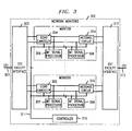
- FIG. 3 a block diagram of an exemplary embodiment of a network monitor of FIGS. 1 and 2 is shown.
- DS1 301 is connected to monitor 302 at a first DS1 facility interface 303.
- DS1 facility interface 303 demultiplexes the 24 DSOs from DS1 301.
- Each DSO or channel is then connected to an echo canceler, for example 304, 305.
- echo canceler 304, 305 the circuit continues to incoming multi-tone signal processors 306, 307 and outgoing multi-tone signal processors 308, 309, respectively.
- Multi-tone signal processors 306 through 309 are connected to controller 310 via a bus 311.
- Controller 310 controls all multi-tone signal processors. All DSOs are remultiplexed at a second DS1 facility interface 312 and connected to DS1 313.
- Controller 310 also provides timing and verification functions. After a signal is detected, controller 310 stores the signal and sets a timer. Controller 310 compares the stored signal to a provisioned list of signals to determine if the stored signal is valid. )f the signal is valid, controller 310 sends a token or other coded representation of the signal received to central control via the LAN (not shown). If the signal is not valid, and the timer has not expired, controller 310 waits for further signals. If further signals are detected, the process outlined above is repeated. If the timer expires, then the storage buffer is cleared.
- controller 310 may provide a confirmation tone or tones to the signaling party to indicated the receipt of a valid signal string through message circuit 314, under the control of the central controller. Controller 310 may also provide announcements through message circuit 314 stating that a partially valid signal was received butt the timerexpired, and/or an announcement of the provision of service.
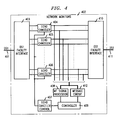
- FIG. 4 An alternative exemplary embodiment of a network monitor according to this invention is shown in FIG. 4.
- DS1 401 is corrected to a network monitor at a DS1 facility 403, as above.
- Each DSO is connected to an echo canceler 404 through 406.
- Each echo canceler 404 through 406 is time multiplexed to a master echo canceler controller 407.
- Each DSO is then tapped to a common multi-tone signal processor 408, which detect signals through time multiplexing each DSO.
- Multi-tone signal processor 408 reports detected signaling to controller409.
- Acommon message circuit412 is connected to each of the DSO, and is under control of the controller 409.
- Each DSO is then remultiplexed at second DS1 facility interface 410 to DS1 411.
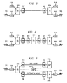
- FIGS. 5 through 9 illustrate additional exemplary embodiments, alternate to FIG. 2, showing the relationship of the network monitor to several different network topologies regularly encountered in network telecommunication.
- FIG. 5 illustrates a general case of a network call and the relationship between the network monitor and the network.
- a call is placed by a calling party from telephone station set 501 to a local office in the local exchange carrier (LEC) 502.
- LEC 502 routes the call to an originating toll switch 503.
- Originating toll switch 503 routes the call, based on traffic and other considerations as known in the art, to a terminating toll switch 504.
- Terminating toll switch 504 routes the call to a destination LEC 505.
- LEC 505 routes the call to telephone station set 506 for the called party.
- While the originating toll switch 503 is routing the call, it is also determining whether the call is to be monitored for customer signaling. If so, then originating toll switch 503 causes network monitor 507 to be activated on the intertoll side of originating toll switch 503, between originating toll switch 503 and the terminating toll switch 504, in this exemplary embodiment.
- Network monitor 508 on the intertoll side of terminating toll switch 504 is not activated in this preferred embodiment, but one skilled in the art may envision features wherein monitoring from network monitor 508 may be advantageous.
- the user of telephone 506 may subscribe to a feature such as multi-way network calling, wherein the user may signal terminating switch 504 to provide a conference circuit.
- the echo cancelers in network monitor 508 are always active. If common channel signaling is available at egress and access, as it is when CPE 509 calls CPE 510, then originating toll switch 503 monitors the signaling network for an indicator of features.
- Monitoring on the intertoll side of originating toll switch 503 is preferred in this embodiment because both directly connected calls and switched-access calls may be monitored from this point.
- Most of the services and features currently envisioned that will require monitoring the network for signaling require action at originating toll switch 503, and the immediacy of having network monitor 507 active at the originating toll switch 503 provides faster service and fewer signaling communications among switches.
- network monitor 507 is on the network side of originating toll switch 503 so that the echo canceler in network monitor 507 may cancel any signaling echo, as described above.
- FIG. 6 illustrates a slightly more complex network call topology.
- a call is placed from a calling party at a telephone 601 connected to LEC 602.
- LEC 602 routes the call to originating toll switch 603, which routes the call to an intermediate toll switch 604 (VIA switch).
- VIP switch intermediate toll switch 604
- a VIA switch 604 may be part of the network connection when the call is over a long distance (i.e., transcontinental), or when there is no direct trunk available, as is known in the art.
- the call is then routed to a terminating toll switch 605, which routes the call to LEC 606.
- LEC 606 routes the call to the telephone 607 of the called party.
- network monitors 608-611 are located at each side of the toll switches.
- originating toll switch 603 monitors signaling connection, such as a connection between CPE 612 and CPE 613.
- FIG. 7 illustrates a relatively common call topology.
- a calling party places a call at telephone 701 through LEC 702.
- LEC 702 routes the call to an originating toll switch 703, as above.
- the calling party dialed a typical toll special code, such as "800", "900", or the like, and toll switch, recognizing the code, queries a network control point (NCP) database 704 via the signaling network.
- NCP network control point
- originating toll switch 703 routes the call to an action control point 705 (ACP).
- ACP 705 returns a further destination telephone number to originating toll switch 703, and originating toll switch 703 in response routes the call to a terminating toll switch 706.
- Terminating toll switch 706 routes the call to LEC 707, and the call is routed to telephone 708 of the called party.
- a network monitor 709 is activated on the network side of the originating toll switch 703 on the channel between the originating 703 and the terminating 706 toll switches. It has been determined that features are unlikely to be employed in the ACP 705 portion of the call, because ACP 705 is likely to prompt and collect DTMF digits for other purposes.
- FIG. 8 illustrates a special call topology for a case where an originating call is placed from telephone 801 through LEC 802 to telephone 805 connected to terminating LEC 804, which are both connected to originating toll switch 803.
- a network monitor may be activated in one of two locations in the call path. If the trunk from LEC 802 is of the type that may be monitored, the network monitor 806 may be enabled, and the call monitored from the LEC side of origination toll switch 803, as described in FIG. 2 above. If the trunk from LEC 802 is not the type that may be monitored, and the calling party subscribes to network features, then origination toll switch 803 routes the call through a VIA switch 811, and back to origination toll switch 803. This topology permits network monitor 807 to be activated, and network monitor 809 to serve as an echo canceler.
- FIG. 9 illustrates an alternative topology to the network topology of FIG. 8.
- a special loop-around trunk 907 may be employed to provide network monitor 906 connections to calls with a common toll switch. In this manner, routing the call to a VIA switch is avoided, thus using fewer network resources and time while providing the same level of features and services.
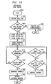
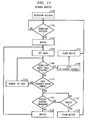
- FIG. 10 is a flowchart which describes the action taken at the originating toll switch. Boxes 1000 through 1014 are performed for in-band signaling (monitoring for DTMF and other signaling). The remainder of the flow chart applies to both in-band and out-of-band (common channel) signaling. Processing begins in box 1000 and proceeds to box 1002 where the toll switch receives an incoming call and receives the automatic number identification of the calling party.
- decision diamond 1004 a decision is made whether this calling party subscribes to features which would require a network monitor. This decision may be made, for example, via a table look up in main memory of the central control of the originating toll switch. Alternatively, the central control of the originating toll switch may send an inquiry to a centralized database at, for example, a network control point. If the calling party may not use features, then processing continues to box 1008 where the call is processed conventionally. This branch ends at 1010.
- processing continues to box 1012, where the calling number is stored and other information is stored on a per call basis (such as billing data, etc.). Processing proceeds to box 1014 where a network monitor is enabled.
- the central control sends an activation message to the network monitor, giving a channel identification.
- a call is completed to the destination and the network monitor is on and is monitoring the trunk for customer signaling. Processing waits in decision diamond 1018 to determine if signaling has been received. If signaling is not received in decision diamond 1018, then a test is made if the calling (originating) party has disconnected in decision diamond 1020. If, in decision diamond 1020, the calling party did not disconnect, then processing returns to the received signaling decision diamond 1018. If the calling party did disconnect in decision diamond 1020, then processing continues to box 1022 where the call is terminated normally. If a monitor were activated, processing then proceeds to box 1024 where a network monitor turn-off message is sent to the network monitor, and processing ends in box 1026.
- central control receives signaling in decision diamond 1018, eitherfrom the signaling channel orthe network monitor, then processing returns to decision diamond 1028 where the received signal string is compared to a list of valid strings. If the string is not valid in decision diamond 1028, then processing returns to decision diamond 1018.
- decision diamond 1030 a determination is made whether this user may use the feature corresponding to the received string.
- the results of this test may depend on call state or other timing. For example, the signal for sequence dialing may only be valid after calling party termination, whereas voice messaging service may be available at any time. Additionally, if ringing is detected, a timer may be set and, upon expiration of the timer, the network monitor may be activated to monitor for signaling to route the call to a voice mail system, for example. If the user may not use the feature, the processing returns to decision diamond 1018.
- the user may be notified that he or she cannot use the feature, by means of a prerecorded message or other audible or visual (ISDN) signal.
- ISDN audible or visual
- FIG. 11 a flowchart at the network monitor is shown. Processing begins when an activation message is received from central control of the toll switch in box 1100. In decision diamond 1102 a determination is made if a signal has been detected by the multi-tone signal processor. If a signal has not been detected, then processing waits at decision diamond 1102. If a signal has been detected in decision diamond 1102, the received signal is buffered in box 1103 and processing proceeds to box 1104 where a timer is set.
- Processing proceeds to decision diamond 1106 where a test is made if the received DTMF digit or digits in the buffer matches one of a table of signals stored in the control unit. If the received signal does match one of the strings of signals, then processing continues to box 1108 where the signals are sent to the central control of the toll switch via the LAN. The buffer is cleared in box 1110, and processing then returns to decision diamond 1102.
- processing proceeds to decision diamond 1112 where a test is made if the received signaling partially match a partiallyval- id sequence. If the received signaling does not match a partially valid sequence, then it is most likely that a false digit has been collected. Processing proceeds to box 1114 where the first digit is removed. Processing then loops back to decision diamond 1106.
- decision diamond 1112 If the received signals match a partially valid sequence in decision diamond 1112, then processing proceeds to decision diamond 1116, where a determination is made whether further signals have been received. Iffunhersignals have been received, then the signals are buffered in box 1122 and processing loops back to box 1104. If further signals have not been received in decision diamond 1116, then processing continues to decision diamond 1118 to determine if the timer has expired. If the timer has expired, then processing proceeds to box 1120 where the buffer is cleared, and processing returns to decision diamond 1102.
- decision diamond 1118 If in decision diamond 1118 the timer has not expired, processing proceeds to decision diamond 1116 where a test is made if further signaling has been received. This processing continues until the control unit receives a turn off message from the central control of the toll switch. In some systems, a "#" character is used as a sting termination character. A check could be made for the "#" character and the string translated to a token and sent to central control in place of decision diamond 1106, or supplemental thereto.
Abstract
Description
- This invention relates to the field of telecommunications networks, and more specifically, to a method and apparatus for detecting customer signaling on the network during the term of a network call and providing access to network services responsive thereto.
- Telecominunications may be described as increasingly "feature rich." That is, there is an ever increasing array of features and services available to individual and business telephone subscribers. Many of the popular features, such as three-way calling, call forwarding and speed calling, are implemented at a local telephone switching system. Such features are generally initiated by the user signaling the local switch. For example, to set up a three-way call a user establishes a first call, flashes the switch-hook to signal the switch that three-way calling is desired, and then dials the telephone number of the third party. In response, the local switch sets up a three-way circuit.
- In contrast to such locally provided features, network (also called toll or long distance) telecommunications supports a different type of features and/or services. Basic network telecommunications access is achieved through 1+ and 0+ calls; wherein 0+ calls provide a variety of credit card or operator assisted features. Other network telecominunications services (such as " 800", "900" and software defined network) require that the user initiates these services by dialing a special 10 digit number. The toll switch recognizes the dialed number as a special number, performs a data base look-up (frequently based on both the dialed number and the calling line identification or "ANI"), and ukes action according to the data retrieved from the data base.
- At least one new feature has recently been proposed for network telecommunications that require the toll switch to recognize customer signaling: U.S. Patent No. 4,932,042 entitled Spontaneous Voice and Data Messaging which issued June 5, 1990, to Baral et al. This feature provides a calling party with the option of leaving a voice mail message after determining that the called party is busy or not answering. After a call is established, the calling party enters a series of dual-tone, multi-frequency (DTMF) signals and, in response, the toll switch routes the calling party to a voice messaging system. There is currently no implemented DTMF detector in toll switches capable of intercepting and translating these customer signals during the entire call for every call through the switch.
- Another proposed network feature is sequence dialing, wherein a user may dial a second destination telephone number after a first connection is terminated without hanging up. This feature is useful for callers from pay telephones, credit card callers, or callers from other countries who have entered identification and billing information into the system, and need to make multiple calls. After the first called party d iscon- nects, the caller enters one or more DTMF digits or other signals which cause the network switch to maintain the connection and then accept a new destination telephone number.
- Therefore, a problem in the art is that there is no capability in network switches that can recognize customer signaling for the entire length of a network call, from pre-answer to post disconnect, for all calls in the network upon which a feature rich network may be built.
- The aforementioned problem is solved and a technical advance is achieved in the art by providing an in-band signaling detector for monitoring calls that enter a telephone network for detecting customer signaling during the entire call, from preanswer through called and calling party disconnect, and providing a system for communicating detected in-band signaling to a processor in a toll switch for providing the desired features and services. Additionally, the signaling network is monitored for out-of-band signaling when common channel signaling is available. If a signaling sequence indicating a feature or service is detected via the signaling network, the toll switch provides the desired features and/or services.
- In accordance with one embodiment of the invention, a network monitor monitoring the network for in-band signaling and comprising a multi-tone signal processor and an echo canceler is connected to a channel. A controller is connected to the multi-tone signal processor for activating and deactivating the multi-tone signal processor, collecting and verifying detected signals, and reporting valid in-band signaling to service logic in a toll switch. Optionally, the controller may provide an audible response to valid or invalid signaling, either by one or more tones or by a prerecorded announcement. The echo canceler is connected to the channel on the local exchange side of the multi-tone signal processor. Advantageously, each side of a call has an echo canceler so that echos of signals from the telephone stations on each end of the call are canceled, and the multi-tone signal processor may determine which telephone station initiated the signaling.
- In accordance with an exemplary method of the invention, a telecommunications network is provided comprising one or more network switches, a plurality of channels interconnected under control of ones of the network switches, and one or more network monitors comprising multi-tone signal processor under control of the network switches and connected to the channels. A call origination is received on one of the channels, one of the network monitors connected to the channel of the call origination is enabled for at lest the interval to call answer or abandonment, and when signaling is received at the network monitor, the network monitor reports the signaling to a switch which provides access to the network service for that channel.
- Optionally, either the calling or the called party may initiate features by signaling the network monitor. The network monitor may advantageously be active during the full duration of the call. Additionally, out-of-band signaling may be monitored for feature requests. The network monitors may be activated by a timer or by out-of-band signaling.
- A more complete understanding of the invention may be obtained from a consideration of the following description in conjunction with the drawings, in which
- FIG. 1 is a block diagram of a telephone network showing a toll switch equipped with network monitors;
- FIG. 2 is an exemplary embodiment of network monitors in the network of FIG. 1;
- FIG. 3 is a functional block diagram of the network monitor of FIGS. 1 and 2;
- FIG. 4 is an alternative embodiment of the network monitor of FIG. 3;
- FIGS. 5 through 9 are block diagrams of several network configurations alternate to FIG. 2, showing the relationship between an active network monitor as described in FIG. 1 and the network;
- FIG. 10 is a flow diagram of actions performed by the toll switch of FIG. 1 in monitoring the network for in-band and out-of band signaling; and
- FIG. 11 is a flow diagram of actions performed by the network monitors of FIGS. 1 through 9 for a typical call requiring monitoring for in-band signaling.
- FIG. 1 is a block diagram of a telephone network 100, incorporating an exemplary embodiment of this invention. A customer at calling
telephone 101 with a given directory number wishes to reach a calledtelephone 102 with a second directory number. The calling party dials the number of the called party, which is determined by a local switch inlocal network 103 as a long distance or network call.Local network 103 extends the call totoll network 104 by seizing an access trunk orchannel 105, as is known in the art, totoll switch 106. The call is received attoll switch 106 by aswitching network 108. - In a first exemplary embodiment of this invention, a
network monitor 107 is connected to accesstrunk 105 betweenlocal network 103 and switchingnetwork 108. The calling customer's telephone number is forwarded from local network via Automatic Number Identification (AM) signals, or common channel signaling (not shown).Central control unit 109 oftoll switch 106 determines whether this access trunk needs to be monitored by looking up the received AMI in table 110 and determining if that AMI is associated with one or more features or services. Alternatively, all calls can be monitored for signaling and then the use of the feature or service may be validated when signaling is detected or when a signal is received on the signaling channel. This would be useful, for example, when a call is made fromCPE 120, and CPE 120 permits the caller to use network features. If the calling or called customer is one that may use special features,network monitor 107 is enabled to monitor the call.Toll switch 106 sets up a connection overtoll network 104 throughnetwork monitor 107 tolocal network 111 viatoll switch 112. Calledtelephone 102 is then alerted bylocal network 111. - Monitoring
access trunk 105 may not be desirable in all cases. Therefore, monitoring the network is performed in a further exemplary embodiment on the intertoll side ofswitching network 108. In this embodiment,outgoing trunk 135 is selected and thennetwork monitor 113 is activated onoutgoing trunk 135. - The calling or called party may, at any time after the network monitor 107,113, or 131 is activated,
signal toll switch 106 to provide a feature or a service. For example, a proposed feature that may use this invention is Spontaneous Voice Messaging, as described in the above-cited Baral et al. patent. After the call is extended totelephone 102, and, for example, the called party does not answer, the calling party may enter a predetermined string, such as *vms (*867 or *Voice Message Service).Network monitor central control 109oftoll switch 106.Central control 109 may then disconnect the call fromlocal network 111 and reconnect the call to a voice message service, as described more fully in Baral et al. - Additionally, the calling party may signal the
toll switch 106 after the called party disconnects (hangs up). Again, this feature is useful for calling parties calling from pay phones who have already entered credit card information orfor international callers who do not want to release the international trunk. The calling party enters a further predetermined string,network monitor central control 109 oftoll switch 106.Toll switch 106 then recognizes the next string as a new destination telephone number, and sets up another call. - Increasingly, common channel signaling is provided for access to and egress from the toll network. For example, customer premise equipment, such as
PBX 120, includes asignaling connection 121 tocentral control 109 oftoll switch 106. Additionally, some local networks, such aslocal network 125 have asignaling connection 126 totoll switch 106 via signaling network and signaling transfer point (not shown), as is known in the art. For connections involving common channel signaling,central control 109 monitors thesignaling network 137 for signaling from the calling party, such asPBX 120, to indicate connection of features. -
Toll switch 106, which in the preferred embodiment is a 4 ESS TM switch manufactured by AT&T Technologies and described in The Bell System Technical Journal, Vol. 56, No. 7, pages 1015-1320, September 1977, is program controlled. It includes acentral control 109 comprisingcentral processing unit 115 andmemory 116.Memory 116 includes aprogram 117 whose action with respect to the network monitor 113 or 131 are described in connection with FIG. 10.Memory 116 also containscall records 118 for maintaining data associated with calls in the system, and a table 110 of directory numbers (ANIs) of those customers who have subscribed to network features and services.Central control 109 is connected via signalingnetwork 137 to the other toll switches in toll network. - In-band customer-initiated signaling on the network is primarily dual-tone, multi-frequency (DTMF) signals from touch tone telephone station sets such as
telephone 101. Network monitors may also monitor for network-initiated signaling, such as ringing, busy, call progress, etc. Therefore, network monitors 107 and 113 comprise a plurality ofmulti-tone signal processors 131 connected to acontrol unit 132.Multi-tone signal processors 131 receive data fromtrunks 135 and determine whether the data received is a recognized signal, such as a DTMF string, a busy signal, or ringing; as is known in the art. If one ofmulti-tone signal processors 131 determines that a signal has been received, the signal is sent to controlunit 132.Control unit 132 collects signals frommulti-tone signal processors 131 and performs timing, verification and reporting functions, as will be described below in connection with FIGS. 9 and 10. - In the preferred embodiment, each network monitor will monitor the voice path of either (or both) the calling and the called party for in-band signaling. Each network monitorwill be capable of monitoring all 24 DSOs within a DS1, both calling and called parties simultaneously.
Multi-tone signal processors 131 may be directed by itscontrol unit 132 to disable signal processing when monitoring is not activated. - Since most toll switches handle several DS1s, there will be many network monitors for each toll switch. In order to control all of the network monitors for any toll switch from one central control, the network monitors are connected to a transaction network, in the preferred embodiment,
LAN 139.LAN 139 provides two-way communication between all of the network monitors in the toll switch andcontroller 140.Controller 140 is connected toprocessor 115 viabus 130, as is known in the art. - FIG. 2 illustrates block diagram of a first exemplary embodiment of this invention in the context of a telephone network showing the relationship among the network monitor and the switches. In a first exemplary embodiment,
telephone 201 places a call tolocal exchange carrier 202 which sends the call to originatingswitch 203. Originatingswitch 203 determines that this caller subscribes to network services and, as a result, activates network monitor 204 for this call on the incoming trunk, on the access side of originatingswitch 203. It is advantageous to have a network monitor on the access side of the switch so that the channel may be monitored while the call is being set up and routed to the destination telephone. This provides monitoring in situations when calls cannot be completed to the terminating switch because, for example, a trunk group is busy. In this exemplary embodiment, the call is connected through the network to terminatingswitch 205. Terminatingswitch 205 routes the call throughnetwork monitor 206 and tolocal exchange 207.Local exchange 207 routes the call totelephone 208. -
Monitor 204 includes, for each channel, anecho canceler 210 on the incoming 211 channel andmulti-tone signal processors Multi-tone signal processors controller 215.Controller 215 communicates with originatingtoll switch 203 viaLAN 216. In each monitor, the echo canceler is on the LEC side of the multi-tone signal processor. This is preferred because a DTMF signal fromtelephone 201, for example, may send a signal to amonitor 204, but the DTMF signal continues through the network to telephone 208 and reflects back into the network, as is known in the art. Thusmulti-tone signal processors telephone 201 would be canceled byecho canceler 217 inmonitor 206. Likewise, signaling echos fromtelephone 208 would be canceled by echo canceier210. In this manner,multi-tone signal processors monitor 204 can determine whether signals originated with the calling 201 or called 208 telephone. - Additionally, a
message circuit monitors Message circuit 220 is under the control ofcontroller 215 and is used to acknowledge a recognized signal sequence, for example. Additionally,message circuit 220 may report invalid signal sequences to the users, or provide other announcements or acknowledgements dependent upon the feature or service. - Turning now to FIG. 3, a block diagram of an exemplary embodiment of a network monitor of FIGS. 1 and 2 is shown. In this embodiment,
DS1 301 is connected to monitor 302 at a firstDS1 facility interface 303.DS1 facility interface 303 demultiplexes the 24 DSOs fromDS1 301. Each DSO or channel is then connected to an echo canceler, for example 304, 305. Fromecho canceler multi-tone signal processors multi-tone signal processors Multi-tone signal processors 306 through 309 are connected tocontroller 310 via abus 311.Controller 310 controls all multi-tone signal processors. All DSOs are remultiplexed at a secondDS1 facility interface 312 and connected to DS1 313. -
Controller 310 also provides timing and verification functions. After a signal is detected,controller 310 stores the signal and sets a timer.Controller 310 compares the stored signal to a provisioned list of signals to determine if the stored signal is valid. )f the signal is valid,controller 310 sends a token or other coded representation of the signal received to central control via the LAN (not shown). If the signal is not valid, and the timer has not expired,controller 310 waits for further signals. If further signals are detected, the process outlined above is repeated. If the timer expires, then the storage buffer is cleared. - Optionally,
controller 310 may provide a confirmation tone or tones to the signaling party to indicated the receipt of a valid signal string throughmessage circuit 314, under the control of the central controller.Controller 310 may also provide announcements throughmessage circuit 314 stating that a partially valid signal was received butt the timerexpired, and/or an announcement of the provision of service. - An alternative exemplary embodiment of a network monitor according to this invention is shown in FIG. 4.
DS1 401 is corrected to a network monitor at aDS1 facility 403, as above. Each DSO is connected to anecho canceler 404 through 406. Eachecho canceler 404 through 406 is time multiplexed to a masterecho canceler controller 407. Each DSO is then tapped to a commonmulti-tone signal processor 408, which detect signals through time multiplexing each DSO.Multi-tone signal processor 408 reports detected signaling to controller409. Acommon message circuit412 is connected to each of the DSO, and is under control of thecontroller 409. Each DSO is then remultiplexed at secondDS1 facility interface 410 toDS1 411. - FIGS. 5 through 9 illustrate additional exemplary embodiments, alternate to FIG. 2, showing the relationship of the network monitor to several different network topologies regularly encountered in network telecommunication. FIG. 5 illustrates a general case of a network call and the relationship between the network monitor and the network. A call is placed by a calling party from telephone station set 501 to a local office in the local exchange carrier (LEC) 502.
LEC 502 routes the call to an originatingtoll switch 503. Originatingtoll switch 503 routes the call, based on traffic and other considerations as known in the art, to a terminatingtoll switch 504. Terminatingtoll switch 504 routes the call to adestination LEC 505.LEC 505 routes the call to telephone station set 506 for the called party. - While the originating
toll switch 503 is routing the call, it is also determining whether the call is to be monitored for customer signaling. If so, then originatingtoll switch 503 causes network monitor 507 to be activated on the intertoll side of originatingtoll switch 503, between originatingtoll switch 503 and the terminatingtoll switch 504, in this exemplary embodiment. Network monitor 508 on the intertoll side of terminatingtoll switch 504 is not activated in this preferred embodiment, but one skilled in the art may envision features wherein monitoring from network monitor 508 may be advantageous. For example, the user oftelephone 506 may subscribe to a feature such as multi-way network calling, wherein the user may signal terminatingswitch 504 to provide a conference circuit. The echo cancelers in network monitor 508 are always active. If common channel signaling is available at egress and access, as it is whenCPE 509 callsCPE 510, then originatingtoll switch 503 monitors the signaling network for an indicator of features. - Monitoring on the intertoll side of originating
toll switch 503 is preferred in this embodiment because both directly connected calls and switched-access calls may be monitored from this point. Most of the services and features currently envisioned that will require monitoring the network for signaling require action at originatingtoll switch 503, and the immediacy of having network monitor 507 active at the originatingtoll switch 503 provides faster service and fewer signaling communications among switches. Additionally, network monitor 507 is on the network side of originatingtoll switch 503 so that the echo canceler in network monitor 507 may cancel any signaling echo, as described above. - FIG. 6 illustrates a slightly more complex network call topology. In FIG. 6, a call is placed from a calling party at a
telephone 601 connected toLEC 602.LEC 602 routes the call to originatingtoll switch 603, which routes the call to an intermediate toll switch 604 (VIA switch). AVIA switch 604 may be part of the network connection when the call is over a long distance (i.e., transcontinental), or when there is no direct trunk available, as is known in the art. The call is then routed to a terminatingtoll switch 605, which routes the call toLEC 606.LEC 606 routes the call to thetelephone 607 of the called party. In the topology of FIG. 6, network monitors 608-611 are located at each side of the toll switches. In the preferred embodiment, only network monitor608 on the intertoll side of originatingtoll switch 603 would be active to provide originatingtoll switch 603 with information regarding customer signaling. Likewise, originatingtoll switch 603 monitors signaling connection, such as a connection betweenCPE 612 andCPE 613. - FIG. 7 illustrates a relatively common call topology. A calling party places a call at
telephone 701 throughLEC 702.LEC 702 routes the call to an originatingtoll switch 703, as above. In this case, the calling party dialed a typical toll special code, such as "800", "900", or the like, and toll switch, recognizing the code, queries a network control point (NCP)database 704 via the signaling network. In response to the database results, originatingtoll switch 703 routes the call to an action control point 705 (ACP). In many cases,ACP 705 returns a further destination telephone number to originatingtoll switch 703, and originatingtoll switch 703 in response routes the call to a terminatingtoll switch 706. Terminatingtoll switch 706 routes the call toLEC 707, and the call is routed to telephone 708 of the called party. In this topology, anetwork monitor 709 is activated on the network side of the originatingtoll switch 703 on the channel between the originating 703 and the terminating 706 toll switches. It has been determined that features are unlikely to be employed in theACP 705 portion of the call, becauseACP 705 is likely to prompt and collect DTMF digits for other purposes. - FIG. 8 illustrates a special call topology for a case where an originating call is placed from
telephone 801 throughLEC 802 to telephone 805 connected to terminatingLEC 804, which are both connected to originatingtoll switch 803. In this case, a network monitor may be activated in one of two locations in the call path. If the trunk fromLEC 802 is of the type that may be monitored, the network monitor 806 may be enabled, and the call monitored from the LEC side oforigination toll switch 803, as described in FIG. 2 above. If the trunk fromLEC 802 is not the type that may be monitored, and the calling party subscribes to network features, thenorigination toll switch 803 routes the call through aVIA switch 811, and back toorigination toll switch 803. This topology permits network monitor 807 to be activated, and network monitor 809 to serve as an echo canceler. - FIG. 9 illustrates an alternative topology to the network topology of FIG. 8. A special loop-around
trunk 907 may be employed to provide network monitor 906 connections to calls with a common toll switch. In this manner, routing the call to a VIA switch is avoided, thus using fewer network resources and time while providing the same level of features and services. - FIG. 10 is a flowchart which describes the action taken at the originating toll switch.
Boxes 1000 through 1014 are performed for in-band signaling (monitoring for DTMF and other signaling). The remainder of the flow chart applies to both in-band and out-of-band (common channel) signaling. Processing begins inbox 1000 and proceeds tobox 1002 where the toll switch receives an incoming call and receives the automatic number identification of the calling party. - Processing continues to
decision diamond 1004, where a decision is made whether this calling party subscribes to features which would require a network monitor. This decision may be made, for example, via a table look up in main memory of the central control of the originating toll switch. Alternatively, the central control of the originating toll switch may send an inquiry to a centralized database at, for example, a network control point. If the calling party may not use features, then processing continues tobox 1008 where the call is processed conventionally. This branch ends at 1010. - If a calling party does subscribe to network features, then processing continues to
box 1012, where the calling number is stored and other information is stored on a per call basis (such as billing data, etc.). Processing proceeds tobox 1014 where a network monitor is enabled. The central control sends an activation message to the network monitor, giving a channel identification. - Parallel to this processing, a call is completed to the destination and the network monitor is on and is monitoring the trunk for customer signaling. Processing waits in
decision diamond 1018 to determine if signaling has been received. If signaling is not received indecision diamond 1018, then a test is made if the calling (originating) party has disconnected indecision diamond 1020. If, indecision diamond 1020, the calling party did not disconnect, then processing returns to the received signalingdecision diamond 1018. If the calling party did disconnect indecision diamond 1020, then processing continues tobox 1022 where the call is terminated normally. If a monitor were activated, processing then proceeds tobox 1024 where a network monitor turn-off message is sent to the network monitor, and processing ends inbox 1026. - If central control receives signaling in
decision diamond 1018, eitherfrom the signaling channel orthe network monitor, then processing returns todecision diamond 1028 where the received signal string is compared to a list of valid strings. If the string is not valid indecision diamond 1028, then processing returns todecision diamond 1018. - If the received string is valid in
decision diamond 1028, then processing proceeds todecision diamond 1030, where a determination is made whether this user may use the feature corresponding to the received string. The results of this test may depend on call state or other timing. For example, the signal for sequence dialing may only be valid after calling party termination, whereas voice messaging service may be available at any time. Additionally, if ringing is detected, a timer may be set and, upon expiration of the timer, the network monitor may be activated to monitor for signaling to route the call to a voice mail system, for example. If the user may not use the feature, the processing returns todecision diamond 1018. Optionally, the user may be notified that he or she cannot use the feature, by means of a prerecorded message or other audible or visual (ISDN) signal. If the caller may use the feature, as determined indecision diamond 1030, then processing proceeds tobox 1032, where the feature is provided, as is known in the art, or hereafter invented. A confirmation,tone or announcement may optionally be given to acknowledge receipt of a valid string. Processing then returns todecision diamond 1018. - Turning now to FIG. 11, a flowchart at the network monitor is shown. Processing begins when an activation message is received from central control of the toll switch in
box 1100. In decision diamond 1102 a determination is made if a signal has been detected by the multi-tone signal processor. If a signal has not been detected, then processing waits atdecision diamond 1102. If a signal has been detected indecision diamond 1102, the received signal is buffered inbox 1103 and processing proceeds tobox 1104 where a timer is set. - Processing proceeds to
decision diamond 1106 where a test is made if the received DTMF digit or digits in the buffer matches one of a table of signals stored in the control unit. If the received signal does match one of the strings of signals, then processing continues tobox 1108 where the signals are sent to the central control of the toll switch via the LAN. The buffer is cleared inbox 1110, and processing then returns todecision diamond 1102. - If the signals so far received do not match a valid string in
decision diamond 1106, then processing proceeds todecision diamond 1112 where a test is made if the received signaling partially match a partiallyval- id sequence. If the received signaling does not match a partially valid sequence, then it is most likely that a false digit has been collected. Processing proceeds tobox 1114 where the first digit is removed. Processing then loops back todecision diamond 1106. - If the received signals match a partially valid sequence in
decision diamond 1112, then processing proceeds todecision diamond 1116, where a determination is made whether further signals have been received. Iffunhersignals have been received, then the signals are buffered inbox 1122 and processing loops back tobox 1104. If further signals have not been received indecision diamond 1116, then processing continues todecision diamond 1118 to determine if the timer has expired. If the timer has expired, then processing proceeds tobox 1120 where the buffer is cleared, and processing returns todecision diamond 1102. - If in
decision diamond 1118 the timer has not expired, processing proceeds todecision diamond 1116 where a test is made if further signaling has been received. This processing continues until the control unit receives a turn off message from the central control of the toll switch. In some systems, a "#" character is used as a sting termination character. A check could be made for the "#" character and the string translated to a token and sent to central control in place ofdecision diamond 1106, or supplemental thereto.
Claims (29)
Applications Claiming Priority (2)
| Application Number | Priority Date | Filing Date | Title |
|---|---|---|---|
| US808348 | 1991-12-16 | ||
| US07/808,348 US5327489A (en) | 1991-12-16 | 1991-12-16 | Method and apparatus for monitoring a network for customer signaling during the term of a call |
Publications (2)
| Publication Number | Publication Date |
|---|---|
| EP0547780A2 true EP0547780A2 (en) | 1993-06-23 |
| EP0547780A3 EP0547780A3 (en) | 1994-09-28 |
Family
ID=25198534
Family Applications (1)
| Application Number | Title | Priority Date | Filing Date |
|---|---|---|---|
| EP9292310601A Withdrawn EP0547780A3 (en) | 1991-12-16 | 1992-11-20 | Method and apparatus for monitoring a network for customer signaling during the term of a call |
Country Status (6)
| Country | Link |
|---|---|
| US (1) | US5327489A (en) |
| EP (1) | EP0547780A3 (en) |
| JP (1) | JPH0685906A (en) |
| KR (1) | KR100274487B1 (en) |
| CA (1) | CA2078599C (en) |
| TW (1) | TW289891B (en) |
Cited By (4)
| Publication number | Priority date | Publication date | Assignee | Title |
|---|---|---|---|---|
| EP0655851A1 (en) * | 1993-10-04 | 1995-05-31 | AT&T Corp. | Call earsdropping arrangement |
| EP0714214A3 (en) * | 1994-11-24 | 1997-04-23 | Tecnomen Oy | Method and apparatus for introducing intelligent functions into a telephone network |
| WO1998027752A1 (en) * | 1996-12-16 | 1998-06-25 | At & T Corp. | Method for expediting access to services of a switched communications network |
| EP0898432A1 (en) * | 1997-08-18 | 1999-02-24 | Telefonaktiebolaget Lm Ericsson | Method and system for detecting the state of dialling a codenumber |
Families Citing this family (45)
| Publication number | Priority date | Publication date | Assignee | Title |
|---|---|---|---|---|
| US5752191A (en) | 1984-09-14 | 1998-05-12 | Accessline Technologies, Inc. | Telephone control system which connects a caller with a subscriber AT A telephone address |
| US6545589B1 (en) | 1984-09-14 | 2003-04-08 | Aspect Communications Corporation | Method and apparatus for managing telecommunications |
| US6201950B1 (en) | 1984-09-14 | 2001-03-13 | Aspect Telecommunications Corporation | Computer-controlled paging and telephone communication system and method |
| US5588037A (en) * | 1984-09-14 | 1996-12-24 | Accessline Technologies, Inc. | Remote access telephone control system |
| US5375161A (en) * | 1984-09-14 | 1994-12-20 | Accessline Technologies, Inc. | Telephone control system with branch routing |
| US6470009B1 (en) * | 1990-11-22 | 2002-10-22 | Sprint Communications Company L.P. | Broadband telecommunications system interface |
| US5491808A (en) * | 1992-09-30 | 1996-02-13 | Conner Peripherals, Inc. | Method for tracking memory allocation in network file server |
| KR960012420B1 (en) * | 1992-12-14 | 1996-09-20 | 재단법인 한국전자통신연구소 | Toll exchanger |
| CA2107453C (en) * | 1992-12-29 | 1997-03-04 | Daniel S. Furman | Caller directed routing of a telephone call based on a dialed suffix |
| US5539804A (en) * | 1994-02-25 | 1996-07-23 | Ctel Compression Telecommunications Corporation | Common channel signalling communication monitoring system |
| US6026156A (en) | 1994-03-18 | 2000-02-15 | Aspect Telecommunications Corporation | Enhanced call waiting |
| US7106843B1 (en) * | 1994-04-19 | 2006-09-12 | T-Netix, Inc. | Computer-based method and apparatus for controlling, monitoring, recording and reporting telephone access |
| US5926533A (en) * | 1994-04-19 | 1999-07-20 | Opus Telecom, Inc. | Computer-based method and apparatus for controlling, monitoring, recording and reporting telephone access |
| US5655013A (en) | 1994-04-19 | 1997-08-05 | Gainsboro; Jay L. | Computer-based method and apparatus for controlling, monitoring, recording and reporting telephone access |
| US7248680B1 (en) | 1994-04-19 | 2007-07-24 | T-Netix, Inc. | Computer-based method and apparatus for controlling, monitoring, recording and reporting telephone access |
| US6205216B1 (en) | 1994-07-29 | 2001-03-20 | British Telecommunications Public Limited Company | Apparatus and method for inter-network communication |
| US5517564A (en) * | 1994-07-29 | 1996-05-14 | British Telecommunications Public Limited Company | Communication apparatus and method |
| US5631958A (en) * | 1994-10-04 | 1997-05-20 | Coherent Communications Systems Corp. | Automatic echo cancellation for an integrated services digital network interface |
| US5546452A (en) | 1995-03-02 | 1996-08-13 | Geotel Communications Corp. | Communications system using a central controller to control at least one network and agent system |
| US6411682B1 (en) | 1995-09-21 | 2002-06-25 | Aspect Telecommunications Corporation | Computer controlled paging and telephone communication system and method |
| US5699348A (en) * | 1995-10-31 | 1997-12-16 | Lucent Technologies Inc. | Method and apparatus for error performance monitoring of a leased telecommunication circuit |
| US5923749A (en) * | 1995-12-06 | 1999-07-13 | Telefonaktiebolaget Lm Ericsson | Method and system for eliminating acoustic echos in a digital telecommunication system |
| US5875234A (en) | 1996-02-14 | 1999-02-23 | Netphone, Inc. | Computer integrated PBX system |
| JP2842363B2 (en) * | 1996-03-13 | 1999-01-06 | 日本電気株式会社 | Echo canceller device |
| US5875230A (en) * | 1996-12-20 | 1999-02-23 | At&T Corp. | Interactive measurement system and method for telecommunication networks |
| US6141406A (en) * | 1997-03-27 | 2000-10-31 | T-Netix, Inc. | Method and apparatus for detecting a secondary destination of a telephone call based on changes in the telephone signal path |
| US7136471B2 (en) * | 1997-03-27 | 2006-11-14 | T-Netix, Inc. | Method and apparatus for detecting a secondary destination of a telephone call based on changes in the telephone signal path |
| AU8576798A (en) | 1997-07-25 | 1999-02-16 | Starvox, Inc. | Apparatus and method for integrated voice gateway |
| US6169724B1 (en) * | 1997-08-20 | 2001-01-02 | At&T Corp. | Egress network service monitor |
| US6076121A (en) * | 1998-03-13 | 2000-06-13 | Levine; Richard C. | Method of network addressing and translation |
| US6643358B2 (en) | 1998-05-27 | 2003-11-04 | 3Com Corporation | Telephone answering apparatus and method for confirming an acoustic command signal |
| US6504912B1 (en) * | 1998-07-07 | 2003-01-07 | At&T Corp. | Method of initiating a call feature request |
| US6665376B1 (en) | 1998-10-23 | 2003-12-16 | T-Netix, Inc. | Selectively activated integrated real-time recording of telephone conversations with automated documentation of consent to call recording |
| US6665380B1 (en) | 1999-01-11 | 2003-12-16 | T-Netix, Inc. | Inmate messaging system and method |
| US6763099B1 (en) | 1999-11-05 | 2004-07-13 | T-Netix, Inc. | Advanced three way call detection system and method using spread spectrum techniques |
| US6668045B1 (en) | 2000-10-30 | 2003-12-23 | T-Netix, Inc. | Message screening, delivery and billing system |
| US7899167B1 (en) | 2003-08-15 | 2011-03-01 | Securus Technologies, Inc. | Centralized call processing |
| US8000269B1 (en) | 2001-07-13 | 2011-08-16 | Securus Technologies, Inc. | Call processing with voice over internet protocol transmission |
| US7860222B1 (en) | 2003-11-24 | 2010-12-28 | Securus Technologies, Inc. | Systems and methods for acquiring, accessing, and analyzing investigative information |
| US7916845B2 (en) | 2006-04-13 | 2011-03-29 | Securus Technologies, Inc. | Unauthorized call activity detection and prevention systems and methods for a Voice over Internet Protocol environment |
| US9026468B2 (en) | 2002-04-29 | 2015-05-05 | Securus Technologies, Inc. | System and method for proactively establishing a third-party payment account for services rendered to a resident of a controlled-environment facility |
| US9020114B2 (en) | 2002-04-29 | 2015-04-28 | Securus Technologies, Inc. | Systems and methods for detecting a call anomaly using biometric identification |
| US7181210B2 (en) * | 2002-09-24 | 2007-02-20 | Redknee Inc. | Method and system for international roaming and call bridging |
| US7529357B1 (en) | 2003-08-15 | 2009-05-05 | Evercom Systems, Inc. | Inmate management and call processing systems and methods |
| US10796392B1 (en) | 2007-05-22 | 2020-10-06 | Securus Technologies, Llc | Systems and methods for facilitating booking, bonding and release |
Citations (7)
| Publication number | Priority date | Publication date | Assignee | Title |
|---|---|---|---|---|
| US4259549A (en) * | 1976-10-21 | 1981-03-31 | Wescom Switching, Inc. | Dialed number to function translator for telecommunications switching system control complex |
| US4555594A (en) * | 1983-08-03 | 1985-11-26 | At&T Bell Laboratories | Telephone interexchange signaling protocol |
| US4599495A (en) * | 1985-02-28 | 1986-07-08 | Northern Telecom Limited | Apparatus for multifrequency signalling tone detection |
| GB2198011A (en) * | 1986-11-28 | 1988-06-02 | American Telephone & Telegraph | Method and apparatus for providing personalized telephone subscriber features at remote locations |
| US4809321A (en) * | 1986-09-22 | 1989-02-28 | Dytel Corporation | Busy/no-answer call completion equipment |
| US5046088A (en) * | 1989-10-31 | 1991-09-03 | Dialogic Corporation | Converter for in-band routing and/or origination information |
| WO1991016779A1 (en) * | 1990-04-23 | 1991-10-31 | Telecom*Usa, Inc. | Long distance telephone switching system with enhanced subscriber services |
Family Cites Families (4)
| Publication number | Priority date | Publication date | Assignee | Title |
|---|---|---|---|---|
| US4918725A (en) * | 1987-11-25 | 1990-04-17 | Nec Corporation | Terminal impedance setting circuit for a two-wire to four-wire converting circuit |
| US4860347A (en) * | 1988-08-10 | 1989-08-22 | Costello Lloyd M | Phone screen security system |
| US4932042A (en) * | 1989-03-03 | 1990-06-05 | At&T Bell Laboratories | Spontaneous voice and data messaging |
| US5033079A (en) * | 1989-05-30 | 1991-07-16 | At&T Bell Laboratories | Establishment of facsimile calls |
-
1991
- 1991-12-16 US US07/808,348 patent/US5327489A/en not_active Expired - Lifetime
-
1992
- 1992-09-10 TW TW081107174A patent/TW289891B/zh active
- 1992-09-18 CA CA002078599A patent/CA2078599C/en not_active Expired - Fee Related
- 1992-11-20 EP EP9292310601A patent/EP0547780A3/en not_active Withdrawn
- 1992-12-10 JP JP4352237A patent/JPH0685906A/en active Pending
- 1992-12-16 KR KR1019920024401A patent/KR100274487B1/en not_active IP Right Cessation
Patent Citations (7)
| Publication number | Priority date | Publication date | Assignee | Title |
|---|---|---|---|---|
| US4259549A (en) * | 1976-10-21 | 1981-03-31 | Wescom Switching, Inc. | Dialed number to function translator for telecommunications switching system control complex |
| US4555594A (en) * | 1983-08-03 | 1985-11-26 | At&T Bell Laboratories | Telephone interexchange signaling protocol |
| US4599495A (en) * | 1985-02-28 | 1986-07-08 | Northern Telecom Limited | Apparatus for multifrequency signalling tone detection |
| US4809321A (en) * | 1986-09-22 | 1989-02-28 | Dytel Corporation | Busy/no-answer call completion equipment |
| GB2198011A (en) * | 1986-11-28 | 1988-06-02 | American Telephone & Telegraph | Method and apparatus for providing personalized telephone subscriber features at remote locations |
| US5046088A (en) * | 1989-10-31 | 1991-09-03 | Dialogic Corporation | Converter for in-band routing and/or origination information |
| WO1991016779A1 (en) * | 1990-04-23 | 1991-10-31 | Telecom*Usa, Inc. | Long distance telephone switching system with enhanced subscriber services |
Non-Patent Citations (1)
| Title |
|---|
| AT&T TECHNICAL JOURNAL, vol.70, no.3/4, Summer 1991, SHORT HILLS US pages 72 - 84, XP271089 HALL ET AL. 'The AT&T Service Circuit Node: A new element for providing Intelligent Network services' * |
Cited By (8)
| Publication number | Priority date | Publication date | Assignee | Title |
|---|---|---|---|---|
| EP0655851A1 (en) * | 1993-10-04 | 1995-05-31 | AT&T Corp. | Call earsdropping arrangement |
| EP0714214A3 (en) * | 1994-11-24 | 1997-04-23 | Tecnomen Oy | Method and apparatus for introducing intelligent functions into a telephone network |
| WO1998027752A1 (en) * | 1996-12-16 | 1998-06-25 | At & T Corp. | Method for expediting access to services of a switched communications network |
| US6031903A (en) * | 1996-12-16 | 2000-02-29 | At&T Corp | Method for expediting access to services on a switched communications network |
| EP0898432A1 (en) * | 1997-08-18 | 1999-02-24 | Telefonaktiebolaget Lm Ericsson | Method and system for detecting the state of dialling a codenumber |
| WO1999009758A1 (en) * | 1997-08-18 | 1999-02-25 | Telefonaktiebolaget Lm Ericsson (Publ) | Method and system for detecting the state of dialling a codenumber |
| US6195427B1 (en) | 1997-08-18 | 2001-02-27 | Telefonaktiebolaget Lm Ericsson (Publ) | Method and system for detecting the state of dialing a codenumber |
| AU750862B2 (en) * | 1997-08-18 | 2002-08-01 | Telefonaktiebolaget Lm Ericsson (Publ) | Method and system for detecting the state of dialling a codenumber |
Also Published As
| Publication number | Publication date |
|---|---|
| TW289891B (en) | 1996-11-01 |
| CA2078599A1 (en) | 1993-06-17 |
| KR100274487B1 (en) | 2000-12-15 |
| US5327489A (en) | 1994-07-05 |
| KR930015567A (en) | 1993-07-24 |
| CA2078599C (en) | 1996-04-02 |
| EP0547780A3 (en) | 1994-09-28 |
| JPH0685906A (en) | 1994-03-25 |
Similar Documents
| Publication | Publication Date | Title |
|---|---|---|
| US5327489A (en) | Method and apparatus for monitoring a network for customer signaling during the term of a call | |
| CA1270315A (en) | Busy/no-answer call completion equipment | |
| US5099509A (en) | Integration of voice store and forward facility | |
| US5007076A (en) | Call announcement arrangement | |
| US4899358A (en) | Call announcement arrangement | |
| US5033079A (en) | Establishment of facsimile calls | |
| US4922490A (en) | Telephone station set | |
| EP0550975B1 (en) | A method of redirecting a telephone call to an alternate destination | |
| JP2686029B2 (en) | Call connection method by automatic call distribution system | |
| US5764748A (en) | Advanced call waiting processing | |
| US5712902A (en) | Telecommunications answering feature method and apparatus | |
| US5848142A (en) | Advanced call waiting processing | |
| US6055305A (en) | Method and apparatus for providing network-based customized call treatment | |
| KR100249582B1 (en) | Method and apparatus for facilitating making collect call | |
| US5046183A (en) | Semi-automated operator assistance telecommunication calls | |
| EP0833525A2 (en) | Method and device for decoding a sequence of signals | |
| US5784448A (en) | Advanced call waiting processing | |
| MXPA03007801A (en) | Service provision. | |
| US5249219A (en) | Integration of voice store and forward facility | |
| US5463683A (en) | Blocked call notification system | |
| JP3021630B2 (en) | Communication system and communication method | |
| US7023978B2 (en) | Telephone voice messaging system and method using off-hook immediate trigger | |
| US5416835A (en) | Automatic signaling-type indicator for use in subsequent interactive dialing | |
| EP0400771A2 (en) | Special service call routing | |
| WO1997050225A2 (en) | A system and a method to provide an audio calling name service implemented through an advanced intelligent network |
Legal Events
| Date | Code | Title | Description |
|---|---|---|---|
| PUAI | Public reference made under article 153(3) epc to a published international application that has entered the european phase |
Free format text: ORIGINAL CODE: 0009012 |
|
| AK | Designated contracting states |
Kind code of ref document: A2 Designated state(s): BE DE ES FR GB IT NL |
|
| RAP3 | Party data changed (applicant data changed or rights of an application transferred) |
Owner name: AT&T CORP. |
|
| PUAL | Search report despatched |
Free format text: ORIGINAL CODE: 0009013 |
|
| AK | Designated contracting states |
Kind code of ref document: A3 Designated state(s): BE DE ES FR GB IT NL |
|
| 17P | Request for examination filed |
Effective date: 19950316 |
|
| 17Q | First examination report despatched |
Effective date: 19980218 |
|
| STAA | Information on the status of an ep patent application or granted ep patent |
Free format text: STATUS: THE APPLICATION IS DEEMED TO BE WITHDRAWN |
|
| 18D | Application deemed to be withdrawn |
Effective date: 20030603 |
|
| REG | Reference to a national code |
Ref country code: HK Ref legal event code: WD Ref document number: 1003466 Country of ref document: HK |