EP0548381B1 - Verfahren zur Uhrzeitführung in Computernetzen - Google Patents
Verfahren zur Uhrzeitführung in Computernetzen Download PDFInfo
- Publication number
- EP0548381B1 EP0548381B1 EP91121712A EP91121712A EP0548381B1 EP 0548381 B1 EP0548381 B1 EP 0548381B1 EP 91121712 A EP91121712 A EP 91121712A EP 91121712 A EP91121712 A EP 91121712A EP 0548381 B1 EP0548381 B1 EP 0548381B1
- Authority
- EP
- European Patent Office
- Prior art keywords
- synchronization
- time
- clock
- time stamps
- network
- Prior art date
- Legal status (The legal status is an assumption and is not a legal conclusion. Google has not performed a legal analysis and makes no representation as to the accuracy of the status listed.)
- Expired - Lifetime
Links
Images


Classifications
-
- H—ELECTRICITY
- H04—ELECTRIC COMMUNICATION TECHNIQUE
- H04J—MULTIPLEX COMMUNICATION
- H04J3/00—Time-division multiplex systems
- H04J3/02—Details
- H04J3/06—Synchronising arrangements
- H04J3/0635—Clock or time synchronisation in a network
- H04J3/0638—Clock or time synchronisation among nodes; Internode synchronisation
-
- G—PHYSICS
- G04—HOROLOGY
- G04G—ELECTRONIC TIME-PIECES
- G04G7/00—Synchronisation
-
- G—PHYSICS
- G06—COMPUTING; CALCULATING OR COUNTING
- G06F—ELECTRIC DIGITAL DATA PROCESSING
- G06F1/00—Details not covered by groups G06F3/00 - G06F13/00 and G06F21/00
- G06F1/04—Generating or distributing clock signals or signals derived directly therefrom
- G06F1/14—Time supervision arrangements, e.g. real time clock
Definitions
- the invention relates to a method for determining the time status of computers which are interconnected in a network hierarchically structured in levels and have a central master clock and have clock modules, synchronization telegrams being fed into the network, with the result that the clock modules present in the computers are continuously synchronized the time of the central master clock is effected.
- a method for determining the time status of computers which are interconnected in a network hierarchically structured in levels and have a central master clock and have clock modules, synchronization telegrams being fed into the network, with the result that the clock modules present in the computers are continuously synchronized the time of the central master clock is effected.
- Such a method is known from EP 0 327 983.
- the invention has for its object to provide a method with which the occurrence of different time bases in the system is recognized with moderate use of the communication means with system-wide clock management and an incorrect linkage of inconsistent time messages is avoided.
- FIG. 1 shows a multi-microcomputer system with three hierarchically structured network levels E1 to E3, of which level E1 is the highest hierarchical level.
- Clock modules provided in the individual computers - indicated by a clock symbol - are each synchronized by a clock module of the next higher level.
- a central master clock HU immediately synchronizes the clock modules on level E1 and thus ultimately determines the time in the entire system.
- Each clock block that synchronizes clock blocks of a lower level is referred to as a master and every clock block that is synchronized but does not itself synchronize clock blocks of a lower level is referred to as a slave.
- a central evaluation unit designated AW, is also provided, in which time stamps which can be output by the clock components are registered, checked for temporal consistency, and the events which trigger them are ordered in time (event ordering).
- Masters M3 and M5 are assumed to be temporarily out of sync with master clock HU.
- One reason for this could be that no synchronization telegrams have reached them anymore or that their computer has been restarted.
- the master clock modules M3 and M5 are free-running, with the result that their times are no longer consistent with those of the rest of the system, but instead establish separate time bases.
- Synchronization cycle is the time interval in which the synchronization or time telegrams follow one another, the time resolution is the externally perceptible time raster step with which the clock module counts up its time, and the synchronization delay is the maximum asynchrony that can occur within a hierarchy level between two clock modules.
- the synchronization delay is essentially determined by the product of the synchronization cycle and quartz tolerance of the watch module.
- FIG. 2 shows the content of the additional information fields provided according to the invention, namely in the left column labeled TEL the information fields of the synchronization telegrams received from these clock blocks and in the right column, labeled ST, the information fields of the time stamps issued by these modules. Both the telegrams and the issued timestamps are to be thought of with the corresponding fields for time and date, which have been omitted for the sake of clarity.
- the first field contains the information about the synchronization source, i.e. the identifier of the respective master from which the received telegram originates.
- the identifier of the master that is in the highest hierarchical level is always entered. This is clear from the CLOCKNR field of the S9 slave. In this way, the field marked with CLOCKNR always contains the identifier of the highest priority synchronization source.
- the next field labeled VERS, consists of three sub-fields for the synchronization telegram and four for the time stamp.
- the third subfield in the synchronization telegram or the fourth subfield in the time stamp indicates the sequential number of the current free running phase of the master. Their content indicates how often the master synchronizing this slave was forced to autonomously determine the time of the clock modules subordinate to it as a result of an intentional or unwanted decoupling from the master clock, for example due to failure of the synchronization telegrams or other faults. In this case, he himself generates the synchronization telegrams for the subordinate hierarchy levels and enters his own identifier in the CLOCKNR field.
- the master clock blocks M3 and M5, which synchronize them, have changed to a free-running phase for the first time.
- the number contained in the fourth subfield of the VERS field can thus be interpreted as the sequential number of a newly established time base related to the higher-level synchronizing master.
- the subfield labeled F0 is an extension of the VERS field for the time stamp. Each clock module sets this subfield to the value T (True) if it is synchronized with a higher-level master clock module.
- the field labeled SLAG which indicates the synchronization delay.
- Each master clock module adds the synchronization delay relevant for its hierarchy level to the synchronization delay communicated to it in the synchronization telegram.
- the values of the synchronization delay therefore accumulate in this field in the individual hierarchy levels.
- the SLAG field has a value of 1.2 msec for the telegram received from slave clock module S1.
- the SLAG field of the telegram received from slave clock module S9 has the value of 1.7 msec, corresponding to the sum of the synchronization delay (1.2 msec) in level E1 and the synchronization delay to be taken into account in level E2 (0.5 msec).
- Each clock module calculates the value of the SLAG field in the time stamp from the sum of the SLAG field in the telegram it receives and the value of the synchronization delay relevant for its hierarchy level. This becomes clear from a comparison of the SLAG fields from the received telegram and the time stamp that can be output for the individual slaves.
- SCYC the telegrams intended for the clock modules have the time interval in which the synchronization telegrams are sent (synchronization cycle).
- this value is important for the calculation of the synchronization delay carried out by the clock module and is also used for plausibility checks in the clock module to be synchronized when the telegrams arrive and for monitoring the regular synchronization, with which the failure of a master clock module is recognizable.
- the time stamps that can be output by the slaves also contain the field labeled GRAN, in which the time resolution is entered.
- the sum of the value entered in this field and the accumulated synchronization delay entered in the SLAG field determines the event resolution of a clock module.
- event resolution is understood to mean the minimum distance that two time stamps to be compared must have, so that the events marked with them can be brought into a clear chronological order in the sense of before / after (event ordering) during the evaluation. This event resolution marked in this way is also simultaneously the maximum difference error that can occur when calculating time intervals between two time stamps.
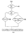
- FIG. 3 uses a flowchart to show how the additional information from two time stamps ST1 and ST2 supplied by different clock modules is used for checking the consistency and then determining the event resolution.
- This is followed by a check whether the subfields F1 have the value T in the two time stamps. In the affirmative case, a check is made as to whether the subfields F2 of the two time stamps ST1 and ST2 have the same value (summer time or winter time).
- the consistency check was successful. If the subfields F1 were not both set to the value T, which e.g. the case could be if both clock modules are synchronized on the same free-running master, then it is checked whether the fields CLOCKNR and VERS of the two time stamps match. If this question is answered in the negative, the two time stamps are rejected as inconsistent, while in the affirmative case the event resolution EA of the two time-consistent time stamps is determined, which results from the larger sum of the values in the fields GRAN and SLAG of both time stamps.
Description
- Die Erfindung betrifft ein Verfahren zur Ermittlung des Zeitzustandes von Computern, welche in einem in Ebenen hierarchisch gegliederten, eine zentrale Hauptuhr aufweisenden Netz zusammengeschaltet sind und Uhrenbausteine aufweisen, wobei Synchronisierungstelegramme in das Netz eingespeist werden, womit eine durchgängige Synchronisierung der in den Computern vorhandenen Uhrenbausteinen auf die Zeit der zentralen Hauptuhr bewirkt wird. Eine derartiges Verfahren ist aus der EP 0 327 983 bekannt.
- Aus der Veröffentlichung IEEE Transactions on Software Engineering 16 (1990) February, No.2 ist ferner bekannt "a hybrid monitor for behavior and performance analysis of distributed systems".
- In der US-PS 4 584 643 ist für eine fehlertoleranten Uhrzeitführung in verteilten Systemen ein Verfahren beschrieben, bei dem alle im Netz vorhandenen Uhren an der Festlegung der Systemzeit beteiligt werden, indem der Mittelwert aus allen ihren Uhrzeitmeldungen gebildet wird. Dies führt im allgemeinen zu einem recht hohen Meldungsaufkommen und damit zu einer erheblichen Inanspruchnahme der Kommunikationsmittel.
- Die Erfindung stellt sich die Aufgabe ein Verfahren anzugeben, mit dem unter mäßiger Inanspruchnahme der Kommunikationsmittel bei systemweiter Uhrzeitführung das Auftreten von unterschiedlichen Zeitbasen im System erkannt und eine fehlerhafte Verknüpfung miteinander nicht konsistenter Uhrzeitmeldungen vermieden wird.
- Gelöst wird diese Aufgabe mit den in den kennzeichnenden Merkmalen von Anspruch 1 angegebenen Maßnahmen. Vorteilhafte weitere Ausgestaltungen der Erfindung sind in den Unteransprüchen angegeben.
- Die Erfindung samt ihren weiteren Ausgestaltungen soll im folgenden anhand der Figuren näher erläutert werden. Dabei zeigt
- Figur 1
- eine beispielhafte Netzkonfiguration,
- Figur 2
- die empfangenen Synchronisierungstelegramme und die ausgegebenen Zeitstempel für einige Uhrenbausteine der Konfiguration nach Figur 1, und
- Figur 3
- ein Flußdiagramm zur Auswertung der Zeitstempel zweier Uhrenbausteine.
- Figur 1 zeigt ein Multimikrocomputersystem mit drei hierarchisch gegliederten Netzwerksebenen E1 bis E3, wovon die Ebene E1 die höchste Hierarchiestufe ist. In den einzelnen Rechnern vorgesehene Uhrenbausteine - angedeutet mit einem Uhrensymbol - werden jeweils von einem Uhrenbaustein der nächsthöheren Ebene synchronisiert. Eine zentrale Hauptuhr HU synchronisiert unmittelbar die Uhrenbausteine der Ebene E1 und bestimmt somit letztlich die Uhrzeit im gesamten System. Jeder Uhrenbaustein, der Uhrenbausteine einer tieferen Ebene synchronisiert, wird als Master bezeichnet und jeder Uhrenbaustein, der zwar synchronisiert wird, jedoch selbst keine Uhrenbausteine einer tieferen Ebene synchronisiert, wird als Slave bezeichnet. Beim dargestellten Beispiel sind also die Master M1 bis M5 mit ihren netzweit gültigen Kennungen (CLOCKNR) und die Slaves S1 bis S11 vorhanden. Es ist weiterhin noch eine zentrale, mit AW bezeichnete Auswerteeinheit vorgesehen, in welcher von den Uhrenbausteinen ausgebbare Zeitstempel registriert, auf zeitliche Konsistenz überprüft und die sie auslösenden Ereignisse zeitlich geordnet werden (event ordering).
- Bei den Mastern M3 und M5 ist angenommen, daß sie vorübergehend nicht mit der Hauptuhr HU synchronisiert sind. Ein Grund dafür könnte sein, daß keine Synchronisierungstelegramme sie mehr erreicht haben oder daß ein Neustart ihres Rechners erfolgt ist. In diesem Fall sind die Master-Uhrenbausteine M3 und M5 freilaufend mit der Folge, daß ihre Uhrzeiten nicht mehr konsistent mit denen des übrigen Systems sind, sondern separate Zeitbasen etablieren.
- Für die drei Netzwerksebenen sollen folgende Synchronisierungsparameter gelten:
E1 E2 E3 Synchronisierungszyklus [sec] 60 10 1 Uhrzeitauflösung [msec] 10 10 1 Synchronisierungsverzug [msec] 1,2 0,5 0,2 - Synchronisierungszyklus ist der zeitliche Abstand, in dem die Synchronisierungs- bzw. Uhrzeittelegramme aufeinander folgen, die Uhrzeitauflösung ist der extern wahrnehmbare zeitliche Rasterschritt mit dem der Uhrenbaustein seine Zeit hochzählt und der Synchronisierungsverzug ist die maximale Asynchronität, die innerhalb einer Hierarchieebene zwischen zwei Uhrenbausteinen auftreten kann. Der Synchronisierungsverzug ist im wesentlichen durch das Produkt von Synchronisierungszyklus und Quarztoleranz des Uhrenbausteins bestimmt.
- Für das vorstehend geschilderte Szenario gibt bezüglich der Slave-Uhrenbausteine S1, S3, S4, S9 und S10 die Figur 2 den Inhalt der erfindungsgemäß vorgesehenen zusätzlichen Informationsfelder wieder und zwar in der linken, mit TEL bezeichneten Spalte die Informationsfelder der von diesen Uhrenbausteinen empfangenen Synchronisierungsstelegrammen und in der rechten, mit ST bezeichneten Spalte die Informationsfelder der von diesen Bausteinen ausgegebenen Zeitstempeln. Sowohl die Telegramme als auch die ausgegebenen Zeitstempel sind noch um entsprechende Felder für Uhrzeit und Datum ergänzt zu denken, welche jedoch der besseren übersichtlichkeit halber weggelassen wurden.
- Das erste, mit CLOCKNR bezeichnete Feld enthält die Information über die Synchronisierungsquelle, d.h., die Kennung des jeweiligen Masters, von dem das empfangene Telegramm orginär stammt. Es wird also immer die Kennung desjenigen Masters eingetragen, der in der hierarchiehöchsten Ebene liegt. Dies wird deutlich beim CLOCKNR-Feld des Slaves S9. Auf diese Weise enthält das mit CLOCKNR gekennzeichnete Feld immer die Kennung der höchstprioren Synchronisierungsquelle.
- Das nächste, mit VERS bezeichnete Feld besteht beim Synchronisierungstelegramm aus drei und beim Uhrzeitstempel aus vier Teilfeldern. In dem mit F1 bezeichneten Teilfeld wird mit T (= True) gekennzeichnet, ob der synchronisierende Master-Uhrenbaustein auf die zentrale Hauptuhr HU synchronisiert ist, oder ob er "freilaufend" mit eigener Zeitbasis synchronisiert. In letzterem Fall ist das Teilfeld F1 auf den Wert F (= False) gesetzt. Wenn das Teilfeld F1 auf den Wert T gesetzt ist, bedeutet der Wert T in dem mit F2 bezeichneten Teilfeld, daß von der Hauptuhr HU Sommerzeit ausgegeben ist, für F2 = F, würde die Hauptuhr Winterzeit ausgeben.
- Im Falle, daß F1 = False eingetragen ist, kennzeichnet das dritte Teilfeld beim Synchronisierungstelegramm bzw. das vierte Teilfeld beim Uhrzeitstempel die laufende Nummer der aktuellen Freilaufphase des Masters. Ihr Inhalt gibt an, wie oft der diesen Slave synchronisierende Master schon gezwungen war, infolge einer gewollten oder ungewollten Abkopplung von der Hauptuhr beispielsweise durch Ausfall der Synchronisierungstelegramme oder sonstigen Störungen, die Uhrzeit der ihm nachgeordneten Uhrenbausteine autonom zu bestimmen. In diesem Fall erzeugt er selbst die Synchronisierungstelegramme für die ihm untergeordneten Hierarchieebenen und trägt im Feld CLOCKNR seine eigene Kennung ein. Aus dem dritten Teilfeld des VERS-Feldes der Slave-Uhrenbausteine S4 und S10 ist ersichtlich, daß die sie synchronisierenden Master- Uhrenbausteine M3 bzw. M5 zum ersten Mal in eine Freilaufphase gewechselt haben. Es kann also die im vierten Teilfeld des VERS-Feldes enthaltene Zahl als die laufende Nummer einer auf den übergeordneten synchronisierenden Master bezogenen jeweils neu etablierten Zeitbasis interpretiert werden. Das mit F0 bezeichnete Teilfeld ist eine Erweiterung des VERS-Feldes für den Zeitstempel. Jeder Uhrenbaustein setzt dieses Teilfeld auf den Wert T (True), wenn er auf einen übergeordneten Master-Uhrenbaustein synchronisiert ist.
- Von besonderer Bedeutung ist das mit SLAG bezeichnete, den Synchronisierungsverzug angebende Feld. Jeder Master-Uhrenbaustein addiert den für seine Hierarchieebene relevanten Synchronisierungsverzug zu dem ihm im Synchronisierungstelegramm mitgeteilten Synchronisierungsverzug. Es akkumulieren sich also in diesem Feld jeweils die Werte des Synchronisierungsverzugs in den einzelnen durchlaufenen Hierarchieebenen. So weist das SLAG-Feld bei dem vom Slave-Uhrenbaustein S1 empfangenen Telegramm den Wert von 1,2 msec. auf, während das SLAG-Feld des vom Slave-Uhrenbaustein S9 empfangenen Telegramms den Wert von 1,7 msec aufweist, entsprechend der Summe aus dem in der Ebene E1 vorhandenen Synchronisierungsverzug (1,2 msec) und dem in der Ebene E2 zu berücksichtigenden Synchronisierungsverzug (0,5 msec). Den Wert des SLAG-Feldes im Zeitstempel berechnet jeder Uhrenbaustein aus der Summe des SLAG-Feldes im von ihm empfangenen Telegramm und dem Wert des für seine Hierarchieebene relevanten Synchronisierungsverzugs. Dies wird aus einem Vergleich der SLAG-Felder vom empfangenen Telegramm und ausgebbaren Zeitstempel für die einzelnen Slaves deutlich.
- Die für die Uhrenbausteine bestimmten Telegramme weisen in ihrem vierten, mit SCYC bezeichneten Feld den zeitlichen Abstand auf, in dem die Synchronisierungstelegramme gesendet werden (Synchronisierungs- Zyklus). Dieser Wert ist einerseits wichtig für die vom Uhrenbaustein vorgenommene Berechnung des Synchronisierungsverzugs und dient des weiteren zu Plausibilitätsprüfungen in dem zu synchronisierenden Uhrenbaustein bei Eintreffen der Telegramme sowie zur Überwachung der regelmäßigen Synchronisierung, womit der Ausfall eines Master-Uhrenbausteins erkennbar wird.
- Als letzte der zusätzlichen Informationen enthalten die von den Slaves ausgebbaren Uhrzeitstempel noch das mit GRAN bezeichnete Feld, in welches die Uhrzeitauflösung eingetragen ist. Die Summe des in diesem Feld eingetragenen Wertes und der im Feld SLAG eingetragene, akkumulierte Synchronisierungsverzug bestimmt die Ereignisauflösung eines Uhrenbaustein. Unter Ereignisauflösung wird in diesem Zusammenhang der Mindestabstand verstanden, den zwei zu vergleichende Zeitstempel haben müssen, damit die damit gekennzeichneten Ereignisse bei der Auswertung in eine eindeutige zeitliche Reihenfolge im Sinne von vorher/nachher (event ordering) gebracht werden können. Diese so gekennzeichnete Ereignisauflösung ist damit gleichzeitig auch der maximale Differenzfehler der bei Berechnung von Zeitintervallen zwischen zwei Zeitstempeln auftreten kann.
- Figur 3 zeigt anhand eines Flußdiagrammes, wie die zusätzlichen Informationen zweier von verschiedenen Uhrenbausteinen gelieferter Zeit stempel ST1 und ST2 zur Konsistenzprüfung und sich daran anschließender Bestimmung der Ereignisauflösung verwendet werden. Zunächst wird geprüft, ob die Teilfelder F0 der beiden Zeitstempel auf den Wert T gesetzt sind. Ist dies nicht der Fall, werden die beiden Zeitstempel unter Ausgabe der Fehlermeldung INK als nicht konsistent abgewiesen, weil aufgrund unterschiedlicher Zeitbasen keine Aussage darüber getroffen werden kann, welcher Zeitstempel das frühere bzw. das spätere Ereignis kennzeichnet. Danach erfolgt die Prüfung, ob die Teilfelder F1 in den beiden Zeitstempeln den Wert T haben. Im bejahenden Fall erfolgt eine Überprüfung, ob die Teilfelder F2 der beiden Zeitstempel ST1 und ST2 denselben Wert haben (Sommerzeit oder Winterzeit). Im bejahenden Fall ist die Konsistenzprüfung erfolgreich verlaufen. Waren bei der Überprüfung der Teilfelder F1 nicht beide auf den Wert T gesetzt, was z.B. der Fall sein könnte, wenn beide Uhrenbausteine auf denselben, freilaufenden Master synchronisiert sind, dann wird geprüft, ob die Felder CLOCKNR und VERS der beiden Zeitstempel übereinstimmen. Wird diese Frage verneint, so werden die beiden Zeitstempel wiederum als inkonsistent abgewiesen, während im bejahenden Fall die Ereignisauflösung EA der beiden zeitkonsistenten Zeitstempel ermittelt wird, die sich aus der jeweils größeren Summe der Werte in den Felder GRAN und SLAG von beiden Zeitstempeln ergibt.
- Die Anwendung dieses Flußdiagramms auf das Beispiel der Figur 2 zeigt, daß mit dem erfindungsgemäßen Verfahren zeitkonsistente Zeitstempel und die Ereignisauflösung schlüssig und widerspruchsfrei bestimmt werden können.
Claims (5)
- Verfahren zur Ermittlung des Zeitzustandes von Computern, welche in einem in Ebenen (E1,E2,E3) hierarchisch gegliederten, eine zentrale Hauptuhr (HU) aufweisenden Netz zusammengeschaltet sind und Uhrenbausteine (M1...M5,S1...S11) aufweisen, wobei
a) Synchronisierungstelegramme (TEL) in das Netz eingespeist werden, womit eine durchgängige Synchronisierung der in den Computern vorhandenen Uhrenbausteinen (M1... M5, S1...S11) auf die Zeit der zentralen Hauptuhr (HU) bewirkt wird, und
dadurch gekennzeichnet, daßb) Zeitstempel (ST;ST1,ST2) vorgesehen sind, welche von den Uhrenbausteinen (S1...S11) der Computer an Endzweigen des Netzes in das Netz eingespeist werden und zumindest Informationsfelder aufweisen betreffend der aktuellen Werte vonb1) Datum und Uhrzeit,b2) Synchronisierungsquelle (CLOCKNR) undb3) Synchronisierungsart (VERS), undc) für die Prüfung der zeitlichen Konsistenz zweier von den Uhrenbausteinen (S1...S11) abgegebener Zeitstempel (ST1,ST2) zumindest deren Informationsfelder betreffend die Synchronisierungsart (VERS) und die Synchronisierungsquelle (CLOCKNR) auf das Vorliegen von Übereinstimmung verglichen werden. - Verfahren nach Anspruch 1, wobeia) die Zeitstempel (ST;ST1,ST2) zusätzliche Informationsfelder aufweisen betreffend der aktuellen Werte vona1) Synchronisierungsverzug (SLAG) unda2) Uhrzeitauflösung (GRAN), undb) nach einer positiv verlaufenen Prüfung der zeitlichen Konsistenz zweier Zeitstempel (ST1,ST2) der minimale zeitliche Abstand (EA) zweier zeitlich noch auflösbaren Ereignisse der Zeitstempel ermittelbar ist, welcher der jeweils größeren Summe ( GRAN(ST1)+SLAG(ST1) bzw. GRAN(ST2)+ SLAG(ST2) ) aus der Uhrzeitauflösung (GRAN) und dem Synchronisierungsverzug (SLAG) von einem der beiden Zeitstempel (ST1 bzw. ST2) entspricht.
- Verfahren nach einem der vorangegangenen Ansprüche, wobei in den Zeitstempeln (ST1,...) eines Uhrenbausteines (S1,...) die Informationen betreffend Synchronisierungsquelle (CLOCKNR) und Synchronisierungsart (VERS) aus dem jeweils zuletzt von einem im Netz übergeordneten Uhrenbaustein (M1...M5) empfangenen Synchronisierungstelegramm (TEL) übernommen werden.
- Verfahren nach einem der vorangegangenen Ansprüche, wobei in die Zeitstempel (ST;ST1,ST2) als Synchronisierungsverzug (SLAG) die Summe aus dem Synchronisierungsverzug in der eigenen Netzwerksebene (E1,E2,E3) und dem im Synchronisierungstelegramm (TEL) mitgeteilten Synchronisierungsverzug der jeweils höheren Netzwerksebenen eingetragen wird (Fig.2).
- Verfahren nach einem der vorangegangenen Ansprüche, wobei die Sychronisierungstelegramme (TEL) ein Informationsfeld (SCYC) betreffend den Synchronisierungszyklus des sendenden Uhrenbausteines (HU,M1...M5) enthalten.
Priority Applications (5)
| Application Number | Priority Date | Filing Date | Title |
|---|---|---|---|
| DE59108895T DE59108895D1 (de) | 1991-12-18 | 1991-12-18 | Verfahren zur Uhrzeitführung in Computernetzen |
| EP91121712A EP0548381B1 (de) | 1991-12-18 | 1991-12-18 | Verfahren zur Uhrzeitführung in Computernetzen |
| AT91121712T ATE160637T1 (de) | 1991-12-18 | 1991-12-18 | Verfahren zur uhrzeitführung in computernetzen |
| JP35316592A JPH05307424A (ja) | 1991-12-18 | 1992-12-11 | 計算機網でのクロックタイム制御方法 |
| US08/488,465 US5579513A (en) | 1991-12-18 | 1995-06-07 | Method for monitoring the synchronization of clocks in computer networks |
Applications Claiming Priority (1)
| Application Number | Priority Date | Filing Date | Title |
|---|---|---|---|
| EP91121712A EP0548381B1 (de) | 1991-12-18 | 1991-12-18 | Verfahren zur Uhrzeitführung in Computernetzen |
Publications (2)
| Publication Number | Publication Date |
|---|---|
| EP0548381A1 EP0548381A1 (de) | 1993-06-30 |
| EP0548381B1 true EP0548381B1 (de) | 1997-11-26 |
Family
ID=8207446
Family Applications (1)
| Application Number | Title | Priority Date | Filing Date |
|---|---|---|---|
| EP91121712A Expired - Lifetime EP0548381B1 (de) | 1991-12-18 | 1991-12-18 | Verfahren zur Uhrzeitführung in Computernetzen |
Country Status (5)
| Country | Link |
|---|---|
| US (1) | US5579513A (de) |
| EP (1) | EP0548381B1 (de) |
| JP (1) | JPH05307424A (de) |
| AT (1) | ATE160637T1 (de) |
| DE (1) | DE59108895D1 (de) |
Families Citing this family (52)
| Publication number | Priority date | Publication date | Assignee | Title |
|---|---|---|---|---|
| EP0650106B1 (de) * | 1993-10-21 | 1998-02-11 | THOMSON multimedia | Verfahren und Vorrichtung zur Synchronisation von an einem Netzwerk angeschlossenen Uhren |
| DE69408506T2 (de) * | 1993-10-21 | 1998-06-25 | Thomson Multimedia Sa | Verfahren und Vorrichtung zur Synchronisation von an einem Netzwerk angeschlossenen Uhren |
| USRE38619E1 (en) | 1995-10-16 | 2004-10-12 | General Instrument Corporation | Method and apparatus for supporting TDMA operating over hybrid fiber coaxial (HFC) or other channels |
| US5666358A (en) * | 1995-10-16 | 1997-09-09 | General Instrument Corporation Of Delaware | Method and apparatus for supporting TDMA operating over hybrid fiber coaxial (HFC) or other channels |
| DE19652617C1 (de) * | 1996-12-18 | 1997-09-11 | Bosch Gmbh Robert | Verfahren und Verwaltung von Weckzeiten und Vorrichtung zur Ausführung dieses Verfahrens |
| US5925107A (en) * | 1997-04-08 | 1999-07-20 | International Business Machines Corporation | Verifying a time-of-day counter |
| US6003091A (en) * | 1997-04-08 | 1999-12-14 | International Business Machines Corporation | Verifying a time-of-day counter |
| WO1999009686A2 (en) * | 1997-08-14 | 1999-02-25 | Tellabs Denmark A/S | A teletransmission network, network elements and a method of identifying the synchronization |
| US6199169B1 (en) | 1998-03-31 | 2001-03-06 | Compaq Computer Corporation | System and method for synchronizing time across a computer cluster |
| US6308280B1 (en) * | 1998-06-25 | 2001-10-23 | Hughes Electronics Corporation | System for synchronizing discrete components to a common clock source |
| DE19832440A1 (de) * | 1998-07-18 | 2000-01-20 | Alcatel Sa | Synchronisationsverfahren, primärer Referenztaktgenerator und Netzelement für ein synchrones digitales Nachrichtenübertragungsnetz |
| US6961314B1 (en) | 1998-10-30 | 2005-11-01 | Broadcom Corporation | Burst receiver for cable modem system |
| US6760316B1 (en) * | 1998-10-30 | 2004-07-06 | Broadcom Corporation | Method and apparatus for the synchronization of multiple cable modem termination system devices |
| ATE412289T1 (de) * | 1998-10-30 | 2008-11-15 | Broadcom Corp | Kabelmodemsystem |
| US7103065B1 (en) * | 1998-10-30 | 2006-09-05 | Broadcom Corporation | Data packet fragmentation in a cable modem system |
| DE29819806U1 (de) | 1998-11-05 | 2000-03-16 | Siemens Ag | Netzwerkteilnehmer |
| WO2000044194A1 (de) * | 1999-01-19 | 2000-07-27 | Siemens Aktiengesellschaft | Verfahren zur zeitsynchronisation eines computerverbundes und computerverbund mit zeitsynchronisation |
| JP3485250B2 (ja) * | 1999-02-17 | 2004-01-13 | 富士通株式会社 | 従属同期装置及び該従属同期装置を有するsdh装置 |
| US6618815B1 (en) | 2000-02-29 | 2003-09-09 | International Business Machines Corporation | Accurate distributed system time of day |
| AT5327U1 (de) * | 2000-03-06 | 2002-05-27 | Keroe Nikolaus Dipl Ing | Verfahren zum synchronisieren von computeruhren in netzwerken für die informationsübertragung, einrichtung zur durchführung dieses verfahrens sowie für die synchronisation von computeruhren geeignetes datenpaket |
| US6742048B1 (en) * | 2000-07-10 | 2004-05-25 | Advanced Micro Devices, Inc. | Multilevel network for distributing trusted time and delegating levels of trust regarding timekeeping |
| US6785666B1 (en) * | 2000-07-11 | 2004-08-31 | Revenue Science, Inc. | Method and system for parsing navigation information |
| US6801876B2 (en) * | 2000-12-08 | 2004-10-05 | Caterpillar Inc | Method and apparatus of managing time for a processing system |
| US7047435B2 (en) * | 2000-12-19 | 2006-05-16 | Siemens Corporate Research, Inc. | System and method for clock-synchronization in distributed systems |
| US20020104004A1 (en) * | 2001-02-01 | 2002-08-01 | Bruno Couillard | Method and apparatus for synchronizing real-time clocks of time stamping cryptographic modules |
| DE10113260B4 (de) * | 2001-03-16 | 2005-10-20 | Siemens Ag | Synchrones, getaktetes Kommunikationssystem mit Relativuhr und Verfahren zum Aufbau eines solchen Systems |
| US6907472B2 (en) * | 2001-03-30 | 2005-06-14 | Yitran Communications Ltd. | Distributed synchronization mechanism for shared communications media based networks |
| DE10121335A1 (de) * | 2001-05-02 | 2002-11-14 | Tenovis Gmbh & Co Kg | Verfahren zur Realisierung einer Systemzeit und Telekommunikationssystem |
| US6901527B2 (en) * | 2001-09-21 | 2005-05-31 | International Business Machines Corporation | Synchronizing multiple time stamps distributed within a computer system with main time of day register |
| FR2834090B1 (fr) * | 2001-12-24 | 2004-02-20 | Bull Sa | Procede et systeme de sauvegarde de l'horloge locale d'un perimetre informatique |
| GB0217708D0 (en) * | 2002-07-31 | 2002-09-11 | Koninkl Philips Electronics Nv | Obtaining configuration data for a data processing apparatus |
| US7079977B2 (en) * | 2002-10-15 | 2006-07-18 | Medtronic, Inc. | Synchronization and calibration of clocks for a medical device and calibrated clock |
| GB2394628B (en) * | 2002-10-25 | 2005-10-19 | Siemens Plc | A method of determining a timing offset between a first clock and a second clock in a communications network |
| BR0300100A (pt) * | 2003-01-10 | 2004-10-13 | Coppe Ufrj | Relógio global distribuìdo para clusters de computadores |
| JP4032421B2 (ja) * | 2003-02-25 | 2008-01-16 | 横河電機株式会社 | 測定データ同期システム |
| US7079046B2 (en) * | 2003-03-28 | 2006-07-18 | Yokogawa Electric Corporation | Multi-point data acquisition apparatus |
| US7613212B1 (en) * | 2003-06-10 | 2009-11-03 | Atrica Israel Ltd. | Centralized clock synchronization for time division multiplexed traffic transported over Ethernet networks |
| US8014378B1 (en) | 2003-10-23 | 2011-09-06 | Itt Manufacturing Enterprise, Inc. | Method and apparatus for automatic control of time-of-day synchronization and merging of networks |
| US7237152B2 (en) * | 2003-10-24 | 2007-06-26 | Honeywell International Inc. | Fail-operational global time reference in a redundant synchronous data bus system |
| US7227858B1 (en) * | 2005-04-07 | 2007-06-05 | The United States Of America As Represented By The National Security Agency | Method of synchronization without broadcasting synchronization signal |
| JP2007155619A (ja) * | 2005-12-07 | 2007-06-21 | Advantest Corp | 試験装置および試験方法 |
| US7644308B2 (en) * | 2006-03-06 | 2010-01-05 | Hewlett-Packard Development Company, L.P. | Hierarchical timestamps |
| JP4726956B2 (ja) * | 2006-06-22 | 2011-07-20 | サンリツオートメイション株式会社 | I/o装置によるネットワークシステムの通信方法 |
| US7451339B2 (en) * | 2006-09-15 | 2008-11-11 | International Business Machines Corporation | Pulse-per-second attachment for STP |
| US8055801B2 (en) * | 2006-09-15 | 2011-11-08 | International Business Machines Corporation | Pulse-per-second attachment for STP |
| FI20075681A0 (fi) * | 2007-09-28 | 2007-09-28 | Nokia Corp | Pääsynvalvonta tukiasemia varten |
| US8582606B2 (en) * | 2010-05-24 | 2013-11-12 | Cortina Systems, Inc. | Network system with synchronization and method of operation thereof |
| US9910419B2 (en) | 2013-09-09 | 2018-03-06 | Harnischfeger Technologies, Inc. | System and method of synchronizing time between multiple systems |
| CN104617633B (zh) * | 2015-02-24 | 2017-01-25 | 刘光辰 | 一种智能电池、一种电量转移总线系统及一种均衡充放电方法 |
| FR3055984B1 (fr) * | 2016-09-15 | 2018-10-05 | Alstom Transp Tech | Procede de synchronisation d'un systeme par determination d'un intervalle de temps local commun |
| US11693448B2 (en) * | 2019-03-05 | 2023-07-04 | Intel Corporation | Timestamp alignment across multiple computing nodes |
| KR20220011904A (ko) * | 2020-07-22 | 2022-02-03 | 에스케이하이닉스 주식회사 | 클럭 분배 네트워크 및 이를 이용하는 반도체 장치 및 반도체 시스템 |
Family Cites Families (11)
| Publication number | Priority date | Publication date | Assignee | Title |
|---|---|---|---|---|
| US4584643A (en) * | 1983-08-31 | 1986-04-22 | International Business Machines Corporation | Decentralized synchronization of clocks |
| US4531185A (en) * | 1983-08-31 | 1985-07-23 | International Business Machines Corporation | Centralized synchronization of clocks |
| US4746920A (en) * | 1986-03-28 | 1988-05-24 | Tandem Computers Incorporated | Method and apparatus for clock management |
| US4805107A (en) * | 1987-04-15 | 1989-02-14 | Allied-Signal Inc. | Task scheduler for a fault tolerant multiple node processing system |
| US5041966A (en) * | 1987-10-06 | 1991-08-20 | Nec Corporation | Partially distributed method for clock synchronization |
| DE3803525C2 (de) * | 1988-02-05 | 1993-12-02 | Licentia Gmbh | Vorrichtung zum Betrieb von absoluten Echtzeituhren in einem eine Zentraluhr und Teilnehmer enthaltenden Prozeßsteuersystem |
| JPH0267033A (ja) * | 1988-09-01 | 1990-03-07 | Fujitsu Ltd | 網同期システム |
| US5241543A (en) * | 1989-01-25 | 1993-08-31 | Hitachi, Ltd. | Independent clocking local area network and nodes used for the same |
| US5001730A (en) * | 1989-03-31 | 1991-03-19 | International Business Machines Corporation | Clock synchronization algorithm for address independent networks |
| US5068877A (en) * | 1990-04-02 | 1991-11-26 | At&T Bell Laboratories | Method for synchronizing interconnected digital equipment |
| US5041798A (en) * | 1990-06-12 | 1991-08-20 | International Business Machines Corporation | Time reference with proportional steering |
-
1991
- 1991-12-18 AT AT91121712T patent/ATE160637T1/de not_active IP Right Cessation
- 1991-12-18 EP EP91121712A patent/EP0548381B1/de not_active Expired - Lifetime
- 1991-12-18 DE DE59108895T patent/DE59108895D1/de not_active Expired - Fee Related
-
1992
- 1992-12-11 JP JP35316592A patent/JPH05307424A/ja not_active Withdrawn
-
1995
- 1995-06-07 US US08/488,465 patent/US5579513A/en not_active Expired - Fee Related
Also Published As
| Publication number | Publication date |
|---|---|
| ATE160637T1 (de) | 1997-12-15 |
| US5579513A (en) | 1996-11-26 |
| JPH05307424A (ja) | 1993-11-19 |
| DE59108895D1 (de) | 1998-01-08 |
| EP0548381A1 (de) | 1993-06-30 |
Similar Documents
| Publication | Publication Date | Title |
|---|---|---|
| EP0548381B1 (de) | Verfahren zur Uhrzeitführung in Computernetzen | |
| DE10211285B4 (de) | Verfahren und Vorrichtung zur Synchronisstion der globalen Zeit von zwei TTCAN-Bussen sowie entsprechendes Bussystem | |
| DE10333932A1 (de) | Synchronisation von datenverarbeitenden Einheiten | |
| DE10361178B4 (de) | Datenalterungsüberwachungsvorrichtung für Sicherheitsnetzwerke | |
| DE3803525C2 (de) | Vorrichtung zum Betrieb von absoluten Echtzeituhren in einem eine Zentraluhr und Teilnehmer enthaltenden Prozeßsteuersystem | |
| EP3022856B1 (de) | Verfahren zur lokalisierung einer frequenzabweichung in einem kommunikationsnetz und entsprechendes kommunikationsnetz | |
| EP2619935A1 (de) | Vorrichtung und verfahren zur bereitstellung einer globalen zeitinformation in ereignisgesteuerter buskommunikation | |
| EP1064589B1 (de) | Verfahren zur synchronisation einer lokalen auf eine zentrale zeitbasis, und vorrichtung zur durchführung des verfahrens mit bevorzugen verwendungen | |
| EP1639758A2 (de) | Verfahren, vorrichtung und system zum austausch von daten über ein bussystem | |
| DE10065117A1 (de) | Verfahren und Kommunikationssystem zum Austausch von Daten zwischen mindestens zwei Teilnehmern über ein Bussystem | |
| EP2299614B1 (de) | Vorrichtung und Verfahren zur Zeitsynchronisation in einem Kommunikationsnetz | |
| EP1428340A2 (de) | Verfahren und vorrichtung zur erzeugung von programmunterbrechungen bei teilnehmern eines bussystems und bussystem | |
| DE10053525B4 (de) | Verfahren und System zur Synchronisation von Teilnehmern einer Kommunikationsverbindung | |
| DE102006001982A1 (de) | Verfahren und Vorrichtung zur Adressvergabe in einem System mit mehreren parallel angeordneten Generatoreinheiten | |
| EP1366416B1 (de) | Fehlertolerante Rechneranordnung und Verfahren zum Betrieb einer derartigen Anordnung | |
| EP1619849A1 (de) | Verfahren zum Synchronisieren eines verteilten Systems | |
| WO1990001246A1 (de) | Verfahren zum erlangen von netzkenntnissen über ein digitales übertragungsnetz | |
| EP1374035A2 (de) | Verfahren und vorrichtung zur bildung von taktimpulsen in einem bussystem mit wenigstens einem teilnehmer, bussystem und teilnehmer | |
| WO2022242921A1 (de) | Verfahren, vorrichtung, computerprogramm und computerlesbares speichermedium zur ermittlung von fehlerbehafteten fahrzeugen | |
| DE102004008667A1 (de) | Verfahren zum synchronen Durchführen von Steuerbefehlen und Vorrichtung zum Durchführen des Verfahrens | |
| DE102022116924A1 (de) | Verfahren, Vorrichtung, Computerprogramm und computerlesbares Speichermedium zur Ermittlung von zumindest einem fehlerbehafteten Fahrzeug | |
| EP0732825A2 (de) | Verfahren zur Synchronisation von Zeitintervallen | |
| DD285462A5 (de) | Verfahren und schaltungsanordnung zur gewinnung von zeitinformationen fuer die echtzeit-prozessdatenerfassung | |
| DE10251912A1 (de) | Synchronisation der Datenverarbeitung in redundanten Datenverarbeitungseinheiten eines Datenverarbeitungssystems | |
| CH616290A5 (en) | Method of transmitting information in remote control systems, and device for implementing the method |
Legal Events
| Date | Code | Title | Description |
|---|---|---|---|
| PUAI | Public reference made under article 153(3) epc to a published international application that has entered the european phase |
Free format text: ORIGINAL CODE: 0009012 |
|
| 17P | Request for examination filed |
Effective date: 19921023 |
|
| AK | Designated contracting states |
Kind code of ref document: A1 Designated state(s): AT BE CH DE FR GB LI NL SE |
|
| 17Q | First examination report despatched |
Effective date: 19960711 |
|
| GRAG | Despatch of communication of intention to grant |
Free format text: ORIGINAL CODE: EPIDOS AGRA |
|
| GRAH | Despatch of communication of intention to grant a patent |
Free format text: ORIGINAL CODE: EPIDOS IGRA |
|
| GRAH | Despatch of communication of intention to grant a patent |
Free format text: ORIGINAL CODE: EPIDOS IGRA |
|
| GRAA | (expected) grant |
Free format text: ORIGINAL CODE: 0009210 |
|
| AK | Designated contracting states |
Kind code of ref document: B1 Designated state(s): AT BE CH DE FR GB LI NL SE |
|
| REF | Corresponds to: |
Ref document number: 160637 Country of ref document: AT Date of ref document: 19971215 Kind code of ref document: T |
|
| REG | Reference to a national code |
Ref country code: CH Ref legal event code: NV Representative=s name: SIEMENS SCHWEIZ AG Ref country code: CH Ref legal event code: EP |
|
| REF | Corresponds to: |
Ref document number: 59108895 Country of ref document: DE Date of ref document: 19980108 |
|
| GBT | Gb: translation of ep patent filed (gb section 77(6)(a)/1977) |
Effective date: 19980112 |
|
| ET | Fr: translation filed | ||
| PGFP | Annual fee paid to national office [announced via postgrant information from national office to epo] |
Ref country code: DE Payment date: 19980220 Year of fee payment: 7 |
|
| PGFP | Annual fee paid to national office [announced via postgrant information from national office to epo] |
Ref country code: CH Payment date: 19980316 Year of fee payment: 7 |
|
| PLBE | No opposition filed within time limit |
Free format text: ORIGINAL CODE: 0009261 |
|
| STAA | Information on the status of an ep patent application or granted ep patent |
Free format text: STATUS: NO OPPOSITION FILED WITHIN TIME LIMIT |
|
| 26N | No opposition filed | ||
| PGFP | Annual fee paid to national office [announced via postgrant information from national office to epo] |
Ref country code: GB Payment date: 19981210 Year of fee payment: 8 Ref country code: BE Payment date: 19981210 Year of fee payment: 8 |
|
| PGFP | Annual fee paid to national office [announced via postgrant information from national office to epo] |
Ref country code: AT Payment date: 19981211 Year of fee payment: 8 |
|
| PGFP | Annual fee paid to national office [announced via postgrant information from national office to epo] |
Ref country code: NL Payment date: 19981217 Year of fee payment: 8 |
|
| PGFP | Annual fee paid to national office [announced via postgrant information from national office to epo] |
Ref country code: FR Payment date: 19981218 Year of fee payment: 8 |
|
| PGFP | Annual fee paid to national office [announced via postgrant information from national office to epo] |
Ref country code: SE Payment date: 19981222 Year of fee payment: 8 |
|
| PG25 | Lapsed in a contracting state [announced via postgrant information from national office to epo] |
Ref country code: LI Free format text: LAPSE BECAUSE OF NON-PAYMENT OF DUE FEES Effective date: 19981231 Ref country code: CH Free format text: LAPSE BECAUSE OF NON-PAYMENT OF DUE FEES Effective date: 19981231 |
|
| REG | Reference to a national code |
Ref country code: CH Ref legal event code: PL |
|
| PG25 | Lapsed in a contracting state [announced via postgrant information from national office to epo] |
Ref country code: DE Free format text: LAPSE BECAUSE OF NON-PAYMENT OF DUE FEES Effective date: 19991001 |
|
| PG25 | Lapsed in a contracting state [announced via postgrant information from national office to epo] |
Ref country code: GB Free format text: LAPSE BECAUSE OF NON-PAYMENT OF DUE FEES Effective date: 19991218 Ref country code: AT Free format text: LAPSE BECAUSE OF NON-PAYMENT OF DUE FEES Effective date: 19991218 |
|
| PG25 | Lapsed in a contracting state [announced via postgrant information from national office to epo] |
Ref country code: SE Free format text: LAPSE BECAUSE OF NON-PAYMENT OF DUE FEES Effective date: 19991219 |
|
| PG25 | Lapsed in a contracting state [announced via postgrant information from national office to epo] |
Ref country code: BE Free format text: LAPSE BECAUSE OF NON-PAYMENT OF DUE FEES Effective date: 19991231 |
|
| BERE | Be: lapsed |
Owner name: SIEMENS A.G. Effective date: 19991231 |
|
| PG25 | Lapsed in a contracting state [announced via postgrant information from national office to epo] |
Ref country code: NL Free format text: LAPSE BECAUSE OF NON-PAYMENT OF DUE FEES Effective date: 20000701 |
|
| GBPC | Gb: european patent ceased through non-payment of renewal fee |
Effective date: 19991218 |
|
| EUG | Se: european patent has lapsed |
Ref document number: 91121712.3 |
|
| PG25 | Lapsed in a contracting state [announced via postgrant information from national office to epo] |
Ref country code: FR Free format text: LAPSE BECAUSE OF NON-PAYMENT OF DUE FEES Effective date: 20000831 |
|
| NLV4 | Nl: lapsed or anulled due to non-payment of the annual fee |
Effective date: 20000701 |
|
| REG | Reference to a national code |
Ref country code: FR Ref legal event code: ST |