EP0549562A2 - Method and apparatus for recording and reproducing information - Google Patents
Method and apparatus for recording and reproducing information Download PDFInfo
- Publication number
- EP0549562A2 EP0549562A2 EP93100423A EP93100423A EP0549562A2 EP 0549562 A2 EP0549562 A2 EP 0549562A2 EP 93100423 A EP93100423 A EP 93100423A EP 93100423 A EP93100423 A EP 93100423A EP 0549562 A2 EP0549562 A2 EP 0549562A2
- Authority
- EP
- European Patent Office
- Prior art keywords
- level
- power level
- power
- recording
- information
- Prior art date
- Legal status (The legal status is an assumption and is not a legal conclusion. Google has not performed a legal analysis and makes no representation as to the accuracy of the status listed.)
- Granted
Links
Images


Classifications
-
- G—PHYSICS
- G11—INFORMATION STORAGE
- G11B—INFORMATION STORAGE BASED ON RELATIVE MOVEMENT BETWEEN RECORD CARRIER AND TRANSDUCER
- G11B7/00—Recording or reproducing by optical means, e.g. recording using a thermal beam of optical radiation by modifying optical properties or the physical structure, reproducing using an optical beam at lower power by sensing optical properties; Record carriers therefor
- G11B7/004—Recording, reproducing or erasing methods; Read, write or erase circuits therefor
- G11B7/006—Overwriting
- G11B7/0062—Overwriting strategies, e.g. recording pulse sequences with erasing level used for phase-change media
-
- G—PHYSICS
- G11—INFORMATION STORAGE
- G11B—INFORMATION STORAGE BASED ON RELATIVE MOVEMENT BETWEEN RECORD CARRIER AND TRANSDUCER
- G11B11/00—Recording on or reproducing from the same record carrier wherein for these two operations the methods are covered by different main groups of groups G11B3/00 - G11B7/00 or by different subgroups of group G11B9/00; Record carriers therefor
- G11B11/10—Recording on or reproducing from the same record carrier wherein for these two operations the methods are covered by different main groups of groups G11B3/00 - G11B7/00 or by different subgroups of group G11B9/00; Record carriers therefor using recording by magnetic means or other means for magnetisation or demagnetisation of a record carrier, e.g. light induced spin magnetisation; Demagnetisation by thermal or stress means in the presence or not of an orienting magnetic field
- G11B11/105—Recording on or reproducing from the same record carrier wherein for these two operations the methods are covered by different main groups of groups G11B3/00 - G11B7/00 or by different subgroups of group G11B9/00; Record carriers therefor using recording by magnetic means or other means for magnetisation or demagnetisation of a record carrier, e.g. light induced spin magnetisation; Demagnetisation by thermal or stress means in the presence or not of an orienting magnetic field using a beam of light or a magnetic field for recording by change of magnetisation and a beam of light for reproducing, i.e. magneto-optical, e.g. light-induced thermomagnetic recording, spin magnetisation recording, Kerr or Faraday effect reproducing
- G11B11/10502—Recording on or reproducing from the same record carrier wherein for these two operations the methods are covered by different main groups of groups G11B3/00 - G11B7/00 or by different subgroups of group G11B9/00; Record carriers therefor using recording by magnetic means or other means for magnetisation or demagnetisation of a record carrier, e.g. light induced spin magnetisation; Demagnetisation by thermal or stress means in the presence or not of an orienting magnetic field using a beam of light or a magnetic field for recording by change of magnetisation and a beam of light for reproducing, i.e. magneto-optical, e.g. light-induced thermomagnetic recording, spin magnetisation recording, Kerr or Faraday effect reproducing characterised by the transducing operation to be executed
- G11B11/10504—Recording
- G11B11/10506—Recording by modulating only the light beam of the transducer
-
- G—PHYSICS
- G11—INFORMATION STORAGE
- G11B—INFORMATION STORAGE BASED ON RELATIVE MOVEMENT BETWEEN RECORD CARRIER AND TRANSDUCER
- G11B11/00—Recording on or reproducing from the same record carrier wherein for these two operations the methods are covered by different main groups of groups G11B3/00 - G11B7/00 or by different subgroups of group G11B9/00; Record carriers therefor
- G11B11/10—Recording on or reproducing from the same record carrier wherein for these two operations the methods are covered by different main groups of groups G11B3/00 - G11B7/00 or by different subgroups of group G11B9/00; Record carriers therefor using recording by magnetic means or other means for magnetisation or demagnetisation of a record carrier, e.g. light induced spin magnetisation; Demagnetisation by thermal or stress means in the presence or not of an orienting magnetic field
- G11B11/105—Recording on or reproducing from the same record carrier wherein for these two operations the methods are covered by different main groups of groups G11B3/00 - G11B7/00 or by different subgroups of group G11B9/00; Record carriers therefor using recording by magnetic means or other means for magnetisation or demagnetisation of a record carrier, e.g. light induced spin magnetisation; Demagnetisation by thermal or stress means in the presence or not of an orienting magnetic field using a beam of light or a magnetic field for recording by change of magnetisation and a beam of light for reproducing, i.e. magneto-optical, e.g. light-induced thermomagnetic recording, spin magnetisation recording, Kerr or Faraday effect reproducing
- G11B11/10502—Recording on or reproducing from the same record carrier wherein for these two operations the methods are covered by different main groups of groups G11B3/00 - G11B7/00 or by different subgroups of group G11B9/00; Record carriers therefor using recording by magnetic means or other means for magnetisation or demagnetisation of a record carrier, e.g. light induced spin magnetisation; Demagnetisation by thermal or stress means in the presence or not of an orienting magnetic field using a beam of light or a magnetic field for recording by change of magnetisation and a beam of light for reproducing, i.e. magneto-optical, e.g. light-induced thermomagnetic recording, spin magnetisation recording, Kerr or Faraday effect reproducing characterised by the transducing operation to be executed
- G11B11/10517—Overwriting or erasing
- G11B11/10519—Direct overwriting, i.e. performing erasing and recording using the same transducing means
- G11B11/10521—Direct overwriting, i.e. performing erasing and recording using the same transducing means using a single light spot
-
- G—PHYSICS
- G11—INFORMATION STORAGE
- G11B—INFORMATION STORAGE BASED ON RELATIVE MOVEMENT BETWEEN RECORD CARRIER AND TRANSDUCER
- G11B11/00—Recording on or reproducing from the same record carrier wherein for these two operations the methods are covered by different main groups of groups G11B3/00 - G11B7/00 or by different subgroups of group G11B9/00; Record carriers therefor
- G11B11/10—Recording on or reproducing from the same record carrier wherein for these two operations the methods are covered by different main groups of groups G11B3/00 - G11B7/00 or by different subgroups of group G11B9/00; Record carriers therefor using recording by magnetic means or other means for magnetisation or demagnetisation of a record carrier, e.g. light induced spin magnetisation; Demagnetisation by thermal or stress means in the presence or not of an orienting magnetic field
- G11B11/11—Recording on or reproducing from the same record carrier wherein for these two operations the methods are covered by different main groups of groups G11B3/00 - G11B7/00 or by different subgroups of group G11B9/00; Record carriers therefor using recording by magnetic means or other means for magnetisation or demagnetisation of a record carrier, e.g. light induced spin magnetisation; Demagnetisation by thermal or stress means in the presence or not of an orienting magnetic field using a beam, e.g. of electrons or X-rays other than a beam of light or a magnetic field for recording
-
- G—PHYSICS
- G11—INFORMATION STORAGE
- G11B—INFORMATION STORAGE BASED ON RELATIVE MOVEMENT BETWEEN RECORD CARRIER AND TRANSDUCER
- G11B7/00—Recording or reproducing by optical means, e.g. recording using a thermal beam of optical radiation by modifying optical properties or the physical structure, reproducing using an optical beam at lower power by sensing optical properties; Record carriers therefor
- G11B7/004—Recording, reproducing or erasing methods; Read, write or erase circuits therefor
- G11B7/0055—Erasing
- G11B7/00557—Erasing involving phase-change media
-
- G—PHYSICS
- G11—INFORMATION STORAGE
- G11B—INFORMATION STORAGE BASED ON RELATIVE MOVEMENT BETWEEN RECORD CARRIER AND TRANSDUCER
- G11B7/00—Recording or reproducing by optical means, e.g. recording using a thermal beam of optical radiation by modifying optical properties or the physical structure, reproducing using an optical beam at lower power by sensing optical properties; Record carriers therefor
- G11B7/004—Recording, reproducing or erasing methods; Read, write or erase circuits therefor
- G11B7/006—Overwriting
-
- G—PHYSICS
- G11—INFORMATION STORAGE
- G11B—INFORMATION STORAGE BASED ON RELATIVE MOVEMENT BETWEEN RECORD CARRIER AND TRANSDUCER
- G11B7/00—Recording or reproducing by optical means, e.g. recording using a thermal beam of optical radiation by modifying optical properties or the physical structure, reproducing using an optical beam at lower power by sensing optical properties; Record carriers therefor
- G11B7/24—Record carriers characterised by shape, structure or physical properties, or by the selection of the material
- G11B7/241—Record carriers characterised by shape, structure or physical properties, or by the selection of the material characterised by the selection of the material
- G11B7/242—Record carriers characterised by shape, structure or physical properties, or by the selection of the material characterised by the selection of the material of recording layers
- G11B7/243—Record carriers characterised by shape, structure or physical properties, or by the selection of the material characterised by the selection of the material of recording layers comprising inorganic materials only, e.g. ablative layers
-
- G—PHYSICS
- G11—INFORMATION STORAGE
- G11B—INFORMATION STORAGE BASED ON RELATIVE MOVEMENT BETWEEN RECORD CARRIER AND TRANSDUCER
- G11B9/00—Recording or reproducing using a method not covered by one of the main groups G11B3/00 - G11B7/00; Record carriers therefor
-
- G—PHYSICS
- G11—INFORMATION STORAGE
- G11B—INFORMATION STORAGE BASED ON RELATIVE MOVEMENT BETWEEN RECORD CARRIER AND TRANSDUCER
- G11B9/00—Recording or reproducing using a method not covered by one of the main groups G11B3/00 - G11B7/00; Record carriers therefor
- G11B9/10—Recording or reproducing using a method not covered by one of the main groups G11B3/00 - G11B7/00; Record carriers therefor using electron beam; Record carriers therefor
-
- G—PHYSICS
- G11—INFORMATION STORAGE
- G11B—INFORMATION STORAGE BASED ON RELATIVE MOVEMENT BETWEEN RECORD CARRIER AND TRANSDUCER
- G11B7/00—Recording or reproducing by optical means, e.g. recording using a thermal beam of optical radiation by modifying optical properties or the physical structure, reproducing using an optical beam at lower power by sensing optical properties; Record carriers therefor
- G11B7/24—Record carriers characterised by shape, structure or physical properties, or by the selection of the material
- G11B7/241—Record carriers characterised by shape, structure or physical properties, or by the selection of the material characterised by the selection of the material
- G11B7/242—Record carriers characterised by shape, structure or physical properties, or by the selection of the material characterised by the selection of the material of recording layers
- G11B7/243—Record carriers characterised by shape, structure or physical properties, or by the selection of the material characterised by the selection of the material of recording layers comprising inorganic materials only, e.g. ablative layers
- G11B2007/24302—Metals or metalloids
- G11B2007/24304—Metals or metalloids group 2 or 12 elements (e.g. Be, Ca, Mg, Zn, Cd)
-
- G—PHYSICS
- G11—INFORMATION STORAGE
- G11B—INFORMATION STORAGE BASED ON RELATIVE MOVEMENT BETWEEN RECORD CARRIER AND TRANSDUCER
- G11B7/00—Recording or reproducing by optical means, e.g. recording using a thermal beam of optical radiation by modifying optical properties or the physical structure, reproducing using an optical beam at lower power by sensing optical properties; Record carriers therefor
- G11B7/24—Record carriers characterised by shape, structure or physical properties, or by the selection of the material
- G11B7/241—Record carriers characterised by shape, structure or physical properties, or by the selection of the material characterised by the selection of the material
- G11B7/242—Record carriers characterised by shape, structure or physical properties, or by the selection of the material characterised by the selection of the material of recording layers
- G11B7/243—Record carriers characterised by shape, structure or physical properties, or by the selection of the material characterised by the selection of the material of recording layers comprising inorganic materials only, e.g. ablative layers
- G11B2007/24302—Metals or metalloids
- G11B2007/2431—Metals or metalloids group 13 elements (B, Al, Ga, In)
-
- G—PHYSICS
- G11—INFORMATION STORAGE
- G11B—INFORMATION STORAGE BASED ON RELATIVE MOVEMENT BETWEEN RECORD CARRIER AND TRANSDUCER
- G11B7/00—Recording or reproducing by optical means, e.g. recording using a thermal beam of optical radiation by modifying optical properties or the physical structure, reproducing using an optical beam at lower power by sensing optical properties; Record carriers therefor
- G11B7/24—Record carriers characterised by shape, structure or physical properties, or by the selection of the material
- G11B7/241—Record carriers characterised by shape, structure or physical properties, or by the selection of the material characterised by the selection of the material
- G11B7/242—Record carriers characterised by shape, structure or physical properties, or by the selection of the material characterised by the selection of the material of recording layers
- G11B7/243—Record carriers characterised by shape, structure or physical properties, or by the selection of the material characterised by the selection of the material of recording layers comprising inorganic materials only, e.g. ablative layers
- G11B2007/24302—Metals or metalloids
- G11B2007/24312—Metals or metalloids group 14 elements (e.g. Si, Ge, Sn)
-
- G—PHYSICS
- G11—INFORMATION STORAGE
- G11B—INFORMATION STORAGE BASED ON RELATIVE MOVEMENT BETWEEN RECORD CARRIER AND TRANSDUCER
- G11B7/00—Recording or reproducing by optical means, e.g. recording using a thermal beam of optical radiation by modifying optical properties or the physical structure, reproducing using an optical beam at lower power by sensing optical properties; Record carriers therefor
- G11B7/24—Record carriers characterised by shape, structure or physical properties, or by the selection of the material
- G11B7/241—Record carriers characterised by shape, structure or physical properties, or by the selection of the material characterised by the selection of the material
- G11B7/242—Record carriers characterised by shape, structure or physical properties, or by the selection of the material characterised by the selection of the material of recording layers
- G11B7/243—Record carriers characterised by shape, structure or physical properties, or by the selection of the material characterised by the selection of the material of recording layers comprising inorganic materials only, e.g. ablative layers
- G11B2007/24302—Metals or metalloids
- G11B2007/24314—Metals or metalloids group 15 elements (e.g. Sb, Bi)
-
- G—PHYSICS
- G11—INFORMATION STORAGE
- G11B—INFORMATION STORAGE BASED ON RELATIVE MOVEMENT BETWEEN RECORD CARRIER AND TRANSDUCER
- G11B7/00—Recording or reproducing by optical means, e.g. recording using a thermal beam of optical radiation by modifying optical properties or the physical structure, reproducing using an optical beam at lower power by sensing optical properties; Record carriers therefor
- G11B7/24—Record carriers characterised by shape, structure or physical properties, or by the selection of the material
- G11B7/241—Record carriers characterised by shape, structure or physical properties, or by the selection of the material characterised by the selection of the material
- G11B7/242—Record carriers characterised by shape, structure or physical properties, or by the selection of the material characterised by the selection of the material of recording layers
- G11B7/243—Record carriers characterised by shape, structure or physical properties, or by the selection of the material characterised by the selection of the material of recording layers comprising inorganic materials only, e.g. ablative layers
- G11B2007/24302—Metals or metalloids
- G11B2007/24316—Metals or metalloids group 16 elements (i.e. chalcogenides, Se, Te)
-
- G—PHYSICS
- G11—INFORMATION STORAGE
- G11B—INFORMATION STORAGE BASED ON RELATIVE MOVEMENT BETWEEN RECORD CARRIER AND TRANSDUCER
- G11B7/00—Recording or reproducing by optical means, e.g. recording using a thermal beam of optical radiation by modifying optical properties or the physical structure, reproducing using an optical beam at lower power by sensing optical properties; Record carriers therefor
- G11B7/24—Record carriers characterised by shape, structure or physical properties, or by the selection of the material
- G11B7/241—Record carriers characterised by shape, structure or physical properties, or by the selection of the material characterised by the selection of the material
- G11B7/242—Record carriers characterised by shape, structure or physical properties, or by the selection of the material characterised by the selection of the material of recording layers
- G11B7/243—Record carriers characterised by shape, structure or physical properties, or by the selection of the material characterised by the selection of the material of recording layers comprising inorganic materials only, e.g. ablative layers
- G11B2007/24318—Non-metallic elements
- G11B2007/24324—Sulfur
-
- G—PHYSICS
- G11—INFORMATION STORAGE
- G11B—INFORMATION STORAGE BASED ON RELATIVE MOVEMENT BETWEEN RECORD CARRIER AND TRANSDUCER
- G11B7/00—Recording or reproducing by optical means, e.g. recording using a thermal beam of optical radiation by modifying optical properties or the physical structure, reproducing using an optical beam at lower power by sensing optical properties; Record carriers therefor
- G11B7/24—Record carriers characterised by shape, structure or physical properties, or by the selection of the material
- G11B7/241—Record carriers characterised by shape, structure or physical properties, or by the selection of the material characterised by the selection of the material
- G11B7/252—Record carriers characterised by shape, structure or physical properties, or by the selection of the material characterised by the selection of the material of layers other than recording layers
- G11B7/257—Record carriers characterised by shape, structure or physical properties, or by the selection of the material characterised by the selection of the material of layers other than recording layers of layers having properties involved in recording or reproduction, e.g. optical interference layers or sensitising layers or dielectric layers, which are protecting the recording layers
- G11B7/2572—Record carriers characterised by shape, structure or physical properties, or by the selection of the material characterised by the selection of the material of layers other than recording layers of layers having properties involved in recording or reproduction, e.g. optical interference layers or sensitising layers or dielectric layers, which are protecting the recording layers consisting essentially of organic materials
-
- G—PHYSICS
- G11—INFORMATION STORAGE
- G11B—INFORMATION STORAGE BASED ON RELATIVE MOVEMENT BETWEEN RECORD CARRIER AND TRANSDUCER
- G11B7/00—Recording or reproducing by optical means, e.g. recording using a thermal beam of optical radiation by modifying optical properties or the physical structure, reproducing using an optical beam at lower power by sensing optical properties; Record carriers therefor
- G11B7/24—Record carriers characterised by shape, structure or physical properties, or by the selection of the material
- G11B7/241—Record carriers characterised by shape, structure or physical properties, or by the selection of the material characterised by the selection of the material
- G11B7/252—Record carriers characterised by shape, structure or physical properties, or by the selection of the material characterised by the selection of the material of layers other than recording layers
- G11B7/257—Record carriers characterised by shape, structure or physical properties, or by the selection of the material characterised by the selection of the material of layers other than recording layers of layers having properties involved in recording or reproduction, e.g. optical interference layers or sensitising layers or dielectric layers, which are protecting the recording layers
- G11B7/2578—Record carriers characterised by shape, structure or physical properties, or by the selection of the material characterised by the selection of the material of layers other than recording layers of layers having properties involved in recording or reproduction, e.g. optical interference layers or sensitising layers or dielectric layers, which are protecting the recording layers consisting essentially of inorganic materials
Landscapes
- Chemical & Material Sciences (AREA)
- Inorganic Chemistry (AREA)
- Physics & Mathematics (AREA)
- Engineering & Computer Science (AREA)
- Plasma & Fusion (AREA)
- Optical Recording Or Reproduction (AREA)
- Optical Record Carriers And Manufacture Thereof (AREA)
- Optical Head (AREA)
Abstract
Description
- The present invention relates to method for recording, reproducing and erasing information by irradiating an energy, beam such as a light or electron beam and information recording medium, and more particularly to method for recording, reproducing and erasing information by a single beam spot by using a phase change and an information recording medium which is effective for use in the above method.
- A prior art method for recording, reproducing and erasing information in a phase change type optical disk is shown in JP-A-59-71140 in which recording is done by irradiating a small circular light spot formed by fully focusing a light beam spot for a short time period to render a recording film to a complete amorphous state by quick heating and cooling, and erasing is done by irradiating an elliptical light spot extending along a track to keep the recording material at a crystallization temperature for a relatively long time so that the amorphous state recorded area is returned to a complete crystalline state. Thus, two different beam spots are used for recording and reproducing.
- A second prior art method is disclosed in JP-A-56-148740 in which a single light beam spot is used to erase recorded information in one or a plurality of revolutions of a disk medium and record information in the next revolution.
- A third prior art method is disclosed in JP-A-56-145530 in which a light which is intensity modulated between at least two power levels is irradiated to simultaneously record and erase information.
- In the first method, since two beam spots are used, two light sources are necessary and an optical system is complex.
- In the second method, it is necessary to rotate the disk medium a number of revolutions to update the information, and hence it takes a long time.
- In the third method, the above problems are resolved but it is necessary to completely crystallize the recording film prior to recording, and tracking at a reproduction power level, automatic focusing and track or sector address confirmation prior to recording are not effected. Further, since an initial power level is not always an erase power level, a leading portion of the previously written information will not be updated if a start position of updating is deviated.
- On the other hand, a recording thin film for the phase change type optical disk is disclosed in JP-B-47-26897 which also describes various thin films such as Te-Ge, As-Te-Ge and Te-O. JP-B-54-41902 discloses various compositions such as Ge₁₀Tl₅Sb₅Se₇₀ and Ge₂₀Bi₁₀Se₇₀. JP-A-57-24039 discloses thin films of Sb₂₅Te12.5Se62.5, Cd₁₄Te₁₄Se₇₂, Bi₂Se₃, Sb₂Se₃, In₂₀Te₂₀Se₆₀, Bi₂₅Te12.5Se62.5, CuSe and Te₃₃Se₆₇.
- However, in the prior art, when the rewritable phase change type recording thin film is used, a crystallization rate is low, a semiconductor laser beam is not well absorved and a sensitivity is low, a reproduced signal intensity is not sufficient, a stability of the amorphous state is low or resistance to oxidation is insufficient.
- It is an object of the present invention to provide a method for recording, reproducing and erasing phase change type information, which can resolve the problems encountered in the prior art method, can record, reproduce and erase information by a simple optical system and can record new information while erasing recorded information in a short time, and also provide a stable phase change type thin film for recording information which is effective to the above method and has good record, reproduce and erase characteristic and a high sensitivity.
- The above object is achieved by varying a power of an energy beam such as a light, electron or ion beam between power levels capable of causing a state change (phase change) during recording of information. More specifically, information may be updated (erasing and rewriting) during one passage of the spot on a recording film. A reproduction level of the updating light spot may be used only for tracking and auto-focusing. The power may be rendered zero from the reproduction level for a very short time without affect to the tracking and auto-focusing, and such is within the scope of the present invention.
- An average composition of the thin film along a thickness of the information recording thin film is represented by a general formula Ax By Cz Dα where x, y and z are atomic percentages and 0 ≦ x ≦ 30, 5 ≦ y ≦ 40, 15 ≦ z ≦ 70 and 30 ≦ α ≦ 80, and D is at least one element selected from Se and S, C is at least one element selected from Sn, As, Sb, Si, Ge, In and Ga, and B is at least one element selected from Zn, Cd, Al, Pb and Bi. The element B has a function to accelerate a crystallization rate, but since it results in lowering of the crystallization temperature, the stability of the amorphous state is lost unless it is added to a high crystallization temperature material. The element A is at least one of elements other than the elements D, C and B, such as Tl, Cu, Ag, Au, Sc, Y, Ti, Zr, V, Nb, Cr, Mo, Mn, Fe, Ru, Co, Rh, Ni, Pd, Hf, Ta, W, Ir, Pt, Hg, B, C, N, P, O, Te, lanthanide element, actinide element, alkaline metal element, alkaline earth metal element, halogen element and inert gas element. One or plural of the elements B, C and D may be elements in the group A if another element in the respective groups is used. For example, in a Bi-In-Se system, S may be added with less than 30 atomic % and with a sum of S and Se being less than 80 atomic % which is an upper limit for the element group D. Of those, the content of Hg, alkaline metal element, alkaline earth metal element and inert gas element is preferably less than 10 atomic %.
- So long as the average composition in the thickness direction of the recording thin film is within the above range, the composition may vary in the direction of the thickness, although the change of the composition is preferably not abrupt.
- There are many states of the recording thin film continuously or discontinuously between two states, for example, between perfect amorphous state and perfect crystalline (polycrystalline) state, Accordingly, by changing a power of an energy beam between two levels, binary or digital recording is attained, and by changing it among three or more levels, analog or multi-level recording is attained.
-
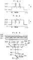
- Fig. 1 shows a change of a laser power in a first embodiment of the present invention,
- Fig. 2 shows a change of a laser power in a second embodiment of the present invention,
- Fig. 3 shows an optical record/reproduce/erase apparatus used in the embodiments of the present invention,
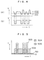
- Fig. 4 shows a reproduced signal waveform in the first embodiment and a method for shaping the waveform,
- Fig. 5 shows a method for combining rewriting waveforms in the first embodiment,
- Fig. 6 shows a principle of multi-value recording in the second embodiment,
- Fig. 7 shows a sectional view of a structure of a recording medium in a third embodiment of the present invention,
- Fig. 8 shows a sectional view of a structure of a recording medium in a fourth embodiment of the present invention, and
- Fig. 9 shows a change of a laser power in a fifth embodiment of the present invention.
- The method of recording, reproducing and erasing information in accordance with the present invention enables so-called overwriting by which new information is recorded while existing record is erased. Thus, information may be updated (erased and rewritten) while an energy beam spot scans a recording film in one run. For example, a disk is rotated while a recording track (between tracking grooves) is rendered almost amorphous state and an area between tracks is rendered crystalline state and information is reproduced by a single laser or electron beam spot. When the beam spot reaches a rewrite position, the power is changed between a plurality of power levels other than a reproduce power level (continuous oscillation) (usually between a record level higher than the reproduce power level and an erase level) to rewrite information. The record level and erase level are defined as laser powers which are optimum for recording and erasing, respectively, to continuously maintain the power. The laser power may be changed by superimposing to a waveform whose power pulsively rises from a reproduce level to a record level in a conventional write-once optical disk, a waveform whose power rises from a power level which is between 0 level to the reproduce level in a rewrite area to an erase level (that is, producing a higher one of those powers). By controlling the power of the superimposing waveform, the rewritable optical disk and the write-once optical disk may be recorded and reproduced by one apparatus. When the power is changed between the two power levels, that is, record power level and erase power level to rewrite information, the decrease of cooling rate due to residual heat of the recording film can be prevented by lowering the power than the lower power level after the higher power level has been reached.
- Where a reciprocal phase change type recording material is used and the near-amorphous state is used as a record state while near-crystalline state is used as an erase state and information is recorded with a higher power than the erase level, the power is raised from the reproduce power level to the erase power level and then the power is pulsively raised from the erase level. Thus, the problem encountered in the third prior art is resolved. In the pulsive power reduction for erasing, it is preferable to significantly reduce the power in an initial stage, so that a temperature suitable for erasing is quickly attained. In the pulsive power rise for recording, it is preferable to significantly raise the power in an initial stage to raise the power above the record power level and then lower the power to the record power level. During the irradiation of the laser beam of the lower power (erasing), the beam spot on the disk medium is preferably enlarged by utilizing wavelength change due to mode change by laser power control, reduction of high frequency superposition or control of amount of return light, or color astigmatism of a lens, or by changing a light path length by utilizing a beam deflector to defocus the beam spot, so that the irradiation time is gained and imperfection of erase information is prevented.
- Which of two or more states of the recording film are to be selected as the record state and erase state is arbitrary. For example, a low reflection state by a high power laser beam irradiation may be selected as the record state or it may be selected as the erase state. Since it is preferable to shorten the irradiation time of the high power laser beam in order to avoid deformation of the recording film, it is preferable to select the high power laser beam irradiation state as the record state.
- In the present invention, when information is recorded by utilizing the reciprocal phase change between the crystalline state and the near-amorphous state (low regularity of atom arrangement or low crystallization) of the recording film, the generation of noise due to ununiform crystallization of an area between tracks when the information is repeatedly rewritten can be prevented by previously rendering the area between the record tracks the crystalline state.
- If a disk rotation speed is high, a point on the disk may not be completely crystallized because of insufficient irradiation time even if the beam of crystallization energy level is irradiated. If the beam of the crystallization level is again irradiated in the rewriting mode, the crystallization proceeds and the reflection coefficient of the crystallized area is not uniform but varies from point to point. In such a case, it is preferable to set a comparator level to a voltage corresponding to a reflection coefficient of a point of the crystallized area which is closest to a reflection coefficient of a point of other state (near-amorphous state), or a reflection coefficient which is intermediate of said reflection coefficient and a reflection coefficient of a point of the near-amorphous state (if it has a range, a reflection coefficient of a point closest to the crystalline state) so that a signal voltage of the crystallization level is clipped to such a level. In this case, if the comparator level is set to an intermediate voltage between a voltage corresponding to the reflection coefficient of the crystalline state and a voltage corresponding to a reflection coefficient of the near-amorphous state, or a voltage closer to the voltage corresponding to the reflection coefficient of the near-amorphous state, the reproduction of information is assured. If the comparator level is set to a voltage between the above intermediate voltage and a voltage of the crystalline state closest to the intermediate voltage, the original waveform can be exactly reproduced. Other waveform shaping device may be used to shape the waveform.
- As to the thin film, the element C such as Sn and the element D such as Se and S may coexist at an appropriate ratio to stably maintain the amorphous state. For example, the ratio of In to Se is preferably 1/0.6 to 1/2, the ratio of Sn and Se is preferably 1/1.2 to 1/2.5, the ratio of Ga and Se is preferably 1/0.8 to 1/1.4. The ratio of Sb and Se is preferably 1/0.4 to 1/2.0 and the ratio of Ge and Se is preferably 1/0.8 to 1/2.5. The element B such as Bi has a function to accelerate the crystallization rate. Of the elements A, a high melting point element (at least one of elements Cu, Ag, Au, Sc, Y, Ti, Zr, V, Nb, Cr, Mo, Mn, Fe, Ru, Co, Rh, Ni and Pd having a melting point of 800°C or higher) facilitates absorption of a long wavelength light such as a semiconductor laser beam to enhance a recording sensitivity, and enhances stability of the amorphous state. It has a melting point of 800°C or higher or produces a compound having the high melting point. Thus, when the crystallization is carried out by the laser beam, it is not molten and high speed crystallization is attained. Of the elements A, Tl and halogen element, particularly I has a function to further accelerate the crystallization. However, if it is added too much, an adverse affect will appear.
- The information recording thin film of the present invention which is within the above composition ranges has an excellent record/reproduce characteristic and a power of a laser beam used to record and reproduce may be low. The present recording thin film also has high stability.
- More preferable ranges of X, Y, Z and α are: 0 ≦ X ≦ 20, 10 ≦ Y ≦ 35, 20 ≦ Z ≦ 55, 35 ≦ α ≦ 70. If the elements A is at least one of the high melting point element Co and Tl and I, it is preferable that 1 ≦ X ≦ 15. If the element C is at least one of As, Sb, Si and Ge, excellent characteristics are attained when 20 ≦ Y ≦ 38, content of the high melting point element such as Co is preferably between 1% and 15%, and 18 ≦ Z ≦ 44.
- A most preferable element C is Sn, a next preferable element is In, and a next preferable element is Ga. For the element D, it is preferable that more Se than S is contained. However, S is preferable because of non-poisonous nature. Of the elements B, a most preferable one is Bi, a next preferable one is Pb and next preferable ones are Zn and Cd. Of the elements A, most preferable ones are Co and Tl, a next preferable one is Ni, and next preferable ones are Ti, V, Cr, Mn and Zr.
- A change of content of each element in a direction of thickness of is usually small although a change in any pattern may exist. For Se and S, it is preferable that it increases more on an inner side in a vicinity of one of the interfaces of the recording thin film. As a result, a resistance to oxidation is enhanced.
- It is preferable that at least one surface of the recording film of the present invention tightly contacts to other material for protection. It is more preferable if both surfaces are protected. Those protection layers may be made of synthetic resin (organic high molecular-weight compound) such as acrylic resin plate, polycarbonate plate, epoxy resin plate, or organic compound such as acryl resin, epoxy resin, polyimide, polyamide, polystylene and polyechylene, or it may be made of an inorganic material primarily consisting of oxide, fluoride, nitride, sulfide, carbide, boride, boron, carbon or metal. It may be a composite material of those materials. The substrate which primarily consists of glass, quartz, safire, iron, titanium or aluminum, may also serve as an inorganic protective layer. The recording film preferably contacts with an inorganic material. Because inorganic materials have higher heat resistance than organic material. When the inorganic material layer (excluding substrate) is thick, cracking may occur, transmissivity may decrease and/or sensitivity may decrease. Accordingly, it is preferable that the inorganic material layer is thin and a thick organic material layer is tightly contacted to the opposite side of the inorganic material layer to the recording film in order to enhance mechanical strength. The organic material layer may be the substrate. Thus, deformation is also prevented. The organic material may be polystylene, acryl resin, polycarbonate, epoxy resin, polyimide, polyamide, ethylene-vinylacetate copolymer known as hot-melt adhesive, or tackifying agent. It may also be UV light curing resin. When the protective layer is made of the inorganic material, it may be formed by electron beam deposition or sputtering. It may be readily formed by reactive sputtering or by forming a film consisting of at least one element of metal, semimetal and semiconductor and reacting its with at least one of oxygen, sulfur and nitrogen. Examples of the inorganic material protective layer are compounds which consist of an oxide of at least one element selected from Ce, La, Si, In, Al, Ge, Pb, Sn, Bi, Te, Ta, Sc, Y, Ti, Zr, V, Nb, Cr and W, a sulfide or selenide of at least one element selected from Cd, Zn, Ga, In, Sb, Ge, Sn and Pb, a fluoride of Mg, Ce or Ca, a nitride of Si, Al, Ta or B, a boride of Ti, a carbide of Si, and/or boron and carbon, whose primary composition is close to one of CeO₂, La₂O₃, SiO, SiO₂, In₂O₃, Al₂O₃, GeO, GeO₂, PbO, SnO, SnO₂, Bi₂O₃, TeO₂, WO₂, WO₃, Ta₂O₅, Sc₂O₃, Y₂O₃, TiO₂, ZrO₂, CdS, ZnS, CdSe, ZnSe, In₂S₃, In₂Se₃, Sb₂S₃, Sb₂Se₃, Ga₂S₃, Ga₂Se₃, MgF₂, CeF₃, CaF₂, GeS, GeSe, GeSe₂, SnS, SnSe, PbS, PbSe, Bi₂Se₃, Bi₂S₃, TaN, Si₃N₄, AlN, Si, TiB₂, B₄C, SiC, B and C.
- In case of the nitride, a composition which is close to TaN, Si₃N₄ or AlN is preferable because a surface reflection coefficient is not so high and a film is stable and strong. In case of the oxide, a composition close to Y₂O₃, Sc₂O₃, CeO₂, TiO₂, ZrO₂, In₂O₃, Al₂O₃, SnO₂ or SiO₂ is preferable. Amorphous Si or C containing hydrogen is also preferable.
- By forming such a protective layer, the increase of noise due to deformation of the recording film in rewriting information is prevented.
- When information is recorded by the phase change, it is one approach to previously crystalize the entire surface of the recording film. When the substrate is made of an organic material, the substrate should not be heated to a high temperature and another crystalization method should be employed. In such a case, irradiation of a laser beam focused to a spot diameter of less than 2 µm, irradiation of UV ray and heating, irradiation of light from a flash lamp such as xenon lamp or Hg-vapor lamp, irradiation of light by a large light spot from a high power gas laser, or irradiation of a laser beam and heating may be preferably used. When the irradiation of light from the gas laser is used, a light spot diameter (half-value width) is preferably between 5 µm and 5 mm in order to attain a high initial crystalization efficiency. Information may also be recorded by crystallizing the amorphous recording thin films or by changing crystal grain sizes in polycrystalline thin film.
- When a light is irradiated to a thin film, a reflected light from the thin film surface and a reflected light from the back surface of the thin film are superimposed and interfere to each other. When a signal is to be read by a change of reflection coefficient, the interference effect is increased by providing a light reflection (absorption) layer closely to the recording film so that a read signal is enhanced. In order to further increase the interference effect, an intermediate layer may be provided between the recording film and the reflection (absorption) layer. The intermediate layer also has an effect to prevent mutual diffusion from occuring between the recording film and the reflection layer when the information is rewritten. The intermediate layer is preferably made of a material which does not significantly absorb a readout light. The thickness of the intermediate layer is preferably between 3 nm and 400 nm and selected such that the reflection coefficient of the recording member is almost minimum in a vicinity of a wavelength of the readout light in the recorded or erased state. The reflection layer may be formed either between the recording film and the substrate or the opposite side thereof. Most preferable range of the thickness of the intermediate layer is between 5 nm and 40 nm. It is preferable that the protective layer made of the inorganic material is formed on the opposite side of the reflection layer to the intermediate layer.
- The recording film of the present invention may be dispersed into the oxide, fluoride, nitride or organic material usable as the protective layer, by co-evaporation or co-sputtering. As a result, a light absorption coefficient can be controlled to enhance a reproduced signal intensity. A ratio of oxygen, fluorine, nitrogen and carbon to the film is preferably less than 40%. When such a composite film is used, it is usual that the crystallization rate decreases and the sensitivity also decreases. However, in the composite film including the organic material, the sensitivity is increased.
- Preferable ranges of the thicknesses of the film and layers are as follows.
- 60 nm - 450 nm
Preferably 180 nm - 350 nm in view of reproduced signal intensity and recording sensitivity. - 15 nm - 50 nm
- 5 nm - 500 nm
(0.1 - 20 mm when protection is made by the inorganic material substrate) - 10 mm - 10 nm
- 3 nm - 400 nm
- 5 nm - 300 nm
Those layers may be formed by vacuum vapor deposition, vapor deposition in a gas, sputtering, ion beam sputtering, ion beam vapor deposition, ion plating, electron beam vapor deposition, injection molding, casting, spin casting or plasma polymerization. - In the recording film of the present invention, it is not necessary to utilize the change between the amorphous state and the crystalline state for the recording of information, but an optical property may be changed by any change of atom arrangement (widely interpreted phase change). For example, a change between polycrystalline states of different average grain sizes of crystals may be utilized for the recording.
- The recording member of the present invention may be used not only in a disk form but also in other forms such as tape and card. It is effective to both the rewriting by a single light beam spot and the rewriting by a multi-light beam spot.
- In order to prevent reduction of a CN ratio due to repetitive recording and erasing of information, an area of transition may be continuously irradiated by a light for unification at a time when the reflectivity of some part on the recording track has changed to a predetermined level by the crystallization of the recording film or when at least one of signal level and noise level has changed to a predetermined level. It is preferable to melt a portion of the recording film for unification. The information recorded prior to the continuous light irradiation is temporarily shifted to another place (device) before melting, and it is rewritten after melting. When the above process is carried out in rewriting information, information to be newly written is temporarily stored in another place. A reflectivity of a predetermined portion of the recording film is always monitored so that the change can be detected as soon as possible.
- It may be automatically carried out at every predetermined number of times of rewriting, every predetermined number of times of reading or predetermined storage time. By irradiating the continuous light which causes melting of the recording film or a sufficient phase change, the irradiated area is rendered uniform state, for example, perfect amorphous state or saturated crystalline state. This means that ununiformity of crystallization or deformation which affects to signal level or noise level is avoided. If ununiformity of reflectivity again increases by rewriting or maintenance of the recording film at a high temperature, the above process is repeated so that the recorded information can be stably maintained for an extended period of time. Regardless of the above process, a signal-to-noise ratio of the reproduced signal is determined by a ratio of a higher level and a lower level (which are called high level and middle level and represent heights from zero power level) when the laser power is changed in the record mode. The middle level is preferably between 55% and 90% of the high level, and more preferably between 65% and 85%. If the power waveform is a sine waveform in which a time at which the power level stays at a level is short, an average value in one quarter of a shortest period of vertical movement of the waveform including a lowest portion of the waveform, and an average value in one quarter of the shortest period of vertical movement including a highest portion of the waveform are set as the middle level and high level, respectively.
- This method can be applied to the recording film which utilizes the change of reflectivity due to the phase change between the amorphous state and the crystalline state, as well as the recording film which records, reproduces and erases information by utilizing the change of reflectivity due to the change of atom arrangement (widely interpreted phase change) between crystalline states or amorphous states such as between a high crystalline state (high regularity of atom arrangement) and a low crystalline state (including polycrystalline states of different average grain sizes of crystals or different types of crystals), and to an magneto-optic recording film.
- Embodiments of the present invention are now explained in detail with reference to the drawings.
- Fig. 1 shows a time transition of a laser power P in a method of recording, reproducing and erasing information in accordance with the present invention. A recording track of an optical disk medium having a diameter of 130 mm and an In-Se recording film which enables rewriting of information by a phase change between a crystalline state and a near-amorphous state, is rendered near-amorphous state in the record tracks, and an area between the record tracks is rendered crystalline state. The record track may also be rendered the crystalline state. In this case, the reflectivity of the crystalline state area is preferably substantially equal to a reflectivity of an erased area. The area between the record tracks is rendered completely crystalline state so that the area is prevented from gradually ununiformly crystallized by diffusion of heat to the area between the tracks when the information is rewritten resulting in mixture of pre-recorded information with a reproduced signal of new information (a kind of residual signal), or the increase of noise is prevented. The optical disk medium is rotated and a laser beam (continuous light) of a reproduce
power level 101 is irradiated with a single light beam spot along the track to perform auto-focusing and tracking. When the beam spot reaches a rewriting position (A), the power level is raised to a crystallization level (erase level) 102. When the beam spot reaches a new record position (B), the power level is pulsively raised to an amorphous power level (record level) 103. Then, the laser power is lowered to thecrystallization level 102. When the cooling rate is reduced by residual heat, the laser power is lowered to a level below the crystallization level (shown by a broken line between C and D) from the amorphous level and then the laser power is raised to the crystallization level. Thereafter, the recorded information is erased. In this case, an average laser power between C and D is preferably between 0 level and a power level immediately below thecrystallization level 102, and more preferably between 1/4 and 3/4 of the crystallization power level. By repeating the above laser power cycle, the information is overwritten. For example, when the rotation speed of the disk was 2400 rpm and a carrier of 1.8 MHz was recorded, a carrier-to-noise (C/N) ratio measured at a band width of 30 KHz was approximately 50 dB. The same position was rewritten with a carrier of 0.9 MHz and a signal of 0.9 MHz was reproduced. A C/N ratio was again approximately 50 dB. The amorphous level (103) laser power was approximately 15 mW, the crystallization level (102) laser power was approximately 7 mW, and the reproduce level (101) laser power was approximately 1 mW. In the above laser power cycle, the information may be recorded by returning the power level from the amorphizing level (103) to the crystallizing level (102), but when the cooling rate is lowered by the residual heat, the C/N ratio or S/N ratio of the reproduced signal may be degraded. By applying a peak power shown by a broken line immediately after the laser power has been raised from thecrystallization level 102 to theamorphous level 103, the amorphizing process of the recording film may be accelerated. The magnitude of the peak power may be higher than theamorphizing level 103 by upto a difference between theamorphizing level 103 and thecrystallization level 102, and preferably between 1/4 to 3/4 of the level difference. - In order to prevent information from being failed to erase, the light beam spot is defocused in the erase mode. This is done by using a focusing lens having a color astigmatism to utilize the fact that the wavelength varies with a change of raser oscillation mode due to a change of laser power. If the beam spot is focused in the record mode, it is defocused when the laser power is at the erase level lower than the record level.
- Fig. 3 shows a construction of an optical record/reproduce/erase appratus used in the embodiment of the present invention. The optical system is essentially identical to an optical system for a commercially available write-once optical disk.
Numeral 301 denotes an optical disk substrate, numeral 302 denotes a recording film, numeral 303 denotes a protective film, numeral 304 denotes a focusing lens, numeral 305 denotes a golvano-mirror, numeral 306 denotes a quarter wavelength plate, numeral 307 denotes a polarization prism, numeral 308 denotes a prism, numeral 309 denotes a coupling lens, numeral 310 denotes a semiconductor laser, numeral 311 denotes a filter, numeral 312 denotes a convex lens, numeral 313 denotes a half-mirror, numeral 314 denotes a cylindrical lens and numeral 315 denotes a knife edge. Since a reflected light from therecording film 302 increases in the record or erase mode to cause malfunction of the servo system, the reflected light passes through thefilter 311 during this mode before the reflected light is directed to an auto-focusingdetector 316 and a tracking andsignal reproducing detector 317 so that an incident light intensity is reduced. Instead of inserting the filter, the output voltage of the detector may be attenuated during these modes. - As described above, when the rotating speed of the disk is high, the irradiation time at a point on the disk is too short to completely crystallize the film. When the light of the crystallization level is again irradiated in the rewriting mode, the crystallization is proceeded. As a result, the reflectivity of the crystallized area is not uniform and the reproduced output voltage V varies from point to point as shown in Fig. 4(a). Accordingly, a
comparator level 403 is set between a reproducedoutput voltage 401 of the amorphous area and a reproducedoutput voltage 402 of a least crystallized area to clip the waveform to produce a waveform shown in Fig. 4(b). When the comparator level is set at an intermediate level of thevoltage - Either one of the crystallization state and amorphous state may be used for recorded state or erased state, respectively. However, since the amorphizing laser power is higher, the time at the amorphizing power level should be shorter than the time at the crystalizing power level. In the commercially available optical disk apparatus, the recording pulse emission time is shorter and hence the amorphous state is preferably used for the recording. As shown in Fig. 5, a current (hatched area 505) corresponding to a difference between the reproduce level and the crystallizing level of the rewriting area is superimposed to a laser drive pulse current (hatched area 504) of the commercial write-once optical disk apparatus to produce a current waveform shown by thick solid line. In this manner, a rewritable optical disk may be used. In Fig. 5, the top of the waveform is limited to prevent the amorphous level of the combined waveform from being too high. By lowering the level of the superimposing current 505 or even reducing it to zero, the information of the write-once optical disk can be recorded or reproduced by the rewritable optical disk apparatus.
- In the present embodiment, when the amorphous state is changed to other crystalline state or the crystalline state is changed to other amorphous state, the crystalline-crystalline or amorphous-amorphous phase change is attained.
- Fig. 2 shows a time transition of a laser power P in another method for recording, reproducing and erasing information in accordance with the present invention. In this embodiment, a
record level 202 is lower than an erase level. The recording film, auto-focusing and tracking used in the present embodiment are identical to those of the Embodiment 1. When the beam spot reaches a rewriting place (a), the laser power is abruptly raised to the erasepower level 203 and held at that level. During this period, the information is erased. When the beam spot reaches a new recording place (b), the laser power is pulsively lowered to therecord power level 202 to record information. The information may be recorded by only lowering the power to therecord level 202 as described above, but if the laser power is lowered below therecord level 202 as shown by a broken line between (b) and (c) at the beginning of lowering the power and then gradually raised to therecord level 202, a time during which the recording area is at a recordable temperature is extended so that the recording is assured. The power level below therecord level 202 is preferably just below therecord level 202, and more preferably between 1/4 to 3/4 of therecord level 202. Then, the laser power is raised to the eraselevel 203. As shown by a broken line between (c) and (d) in Fig. 2, the power is raised above the eraselevel 203 and then lowered to the eraselevel 203 so that the erasing is assured. The average power between (c) and (d) may be the erasepower level 203 plus a difference between the eraselevel 203 and therecord level 202 and preferably 1/4 to 3/4 of such difference. The method for preventing the failure of erasing information is same as that of the Embodiment 1, and the information is recorded, reproduced and erased in the present embodiment by using the optical system of the Embodiment 1 shown in Fig. 1. - The change of the laser power P when multi-level recording is carried out in the present embodiment is shown in Fig. 6a and a reproduced voltage waveform V is shown in Fig. 6b.
Numeral 601 denotes a reproduce level, numeral 602 denotes a record level by crystallization, and numeral 603 denotes an erase level. In Fig. 6, the number of record states is three, but by increasing the number of levels, multi-level recording is attained, and by continuously changing the level, analog recording is attained. Since the change of power level and the change of reproduced voltage are normally not linearly related, at least one of the recording waveform and the reproduced waveform must be converted in order to attain a desired reproduced waveform. - The present embodiment relates to a recording medium suitable for the above record/reproduce/erase method.
- A replica of tracking grooves which also functions as a protective layer was formed by ultraviolet ray curing resin on a surface of a disk-shaped chemically reinforced (hardened) glass plate having a diameter of 13 cm and a thickness of 1.2 mm, and a circumference was divided into 32 sectors. At a beginning of each sector, track address and sector address (called header) were inserted in a form of pit at a hill section between the grooves to form a substrate 719 (Fig. 7). An SiO₂ layer having a thickness of approximately 300 nm which serves as an anti-reflection layer/protective layer was formed on the
substrate 719 by magnetron sputtering. - A recording film 721 having a composition of Bi₂₀In₃₀Se₅₀ was formed on the
SiO₂ layer 720 on thesubstrate 719 to a thickness of approximately 250 nm by magnetron sputtering. The film thickness was selected such that a reflectivity was almost minimum in a vicinity of a laser beam wavelength used for reading when the lights reflected by the front surface and back surface of the recording film interfere and the recording film was in the amorphous state or low crystalline state. A protective layer 722 having a composition close to SiO₂ was then formed to a thickness of approximately 300 nm by magnetron sputtering. Similarly, a protective layer 720' having a composition close to SiO₂, a recording film 721' having a composition of Bi₂₀In₃₀Se₅₀ and a protective layer 722' having a composition close to SiO₂ were vapor-deposited on another similar substrate 719'. Ultraviolet ray curing resin protective layers 723 and 723' were formed on the vapor-deposited films on thesubstrates 719 and 719' to a thickness of approximately 50 µm, and those substrates were bonded together by an organic material bonding layer 724 with the ultraviolet ray curing resin layers 723 and 723' being inside, to prepare a disk. - The disk thus prepared was heated to 150°C for about one hour. Then, the disk was rotated and urgon ion laser beams (wavelength 488 nm) focused by lenses having a numerical aperture of 0.05 were irradiated onto both surfaces of the disk to fully crystallize the recording films 721 and 721'. Information was recorded in the following manner. The disk was rotated at 1200 rpm and the semiconductor laser beam (wavelength 820 nm) was kept at a non-recording level and focused by a lens in the recording head. The beam was irradiated to one of the recording films through the substrate and a reflected light is detected so that the center of the light spot always aligns to a mid-point between the tracking grooves. In this manner, an influence of noise generated by the grooves is avoided. The laser beam was auto-focused so that it was focused onto the recording film while the head was tracked, and the laser power was varied in accordance with the information signal as shown in the Embodiments 1 and 2 to record the information. The head was jumped to another groove as required. As a result of the recording, the reflectivity of the recording film was changed due to the change into the amorphous state. With this recording film, the recorded information may be erased by irradiating a recording light spot having a reduced power or a laser beam having a larger trackwise length spot and a larger spread toward the adjacent track than the diameter of the recording light spot. When the information is erased by reducing the power of the recording light spot, the waveforms shown in the Embodiments 1 and 2 may be used to rewrite the information in one revolution of the disk. The recording and erasing of the information were possible over more than 3 x 10⁵ times. When the SiO₂ layers on and under the recording film were omitted, noise increased after several times of recording and erasing.
- The information was read in the following manner. The disk was rotated at 1200 rpm and a low power semiconductor laser beam which did not couse recording or erasing was irradiated to the disk while the head was tracked and the laser beam was auto-focused, and a reflected light was detected to reproduce the information. In the present embodiment, a signal output of approximately 100 mV was produced. The recording film of the present embodiment has a high resistance to oxidization. When the recording film having no SiO₂ protective film formed thereon was left in an environment of 60°C and relative humidity 95%, no significant oxidization was observed.
- In the Bi-In-Se system recording film, Co was added with the relative composition of other elements being kept constant. A laser beam power necessary for recording and a crystallization temperature changed with respect to the Co content (X %) as shown below.
Recording laser power Crystallization temperature X = 0 12 mW 220°C X = 1 8 mW 250°C X = 2 8 mW 280°C X = 10 8 mW 350°C - The reproduced signal amplitude changed as shown below.
Reproduced signal amplitude X = 15 80 mV X = 20 60 mV X = 30 20 mV - When the content of In was changed with the relative composition of other elements being kept constant, the crystallization temperature for linear heating changed as shown below.
Crystallization temperature Noise level (relative ratio) Z = 0 80°C 0 dB Z = 15 120°C 0 dB Z = 20 200°C 0 dB Z = 45 250°C +1 dB Z = 55 200°C +30 dB Z = 70 120°C +40 dB Z = 80 Crystallized from the time of film formation +40 dB - When the content of Se was changed with the relative composition of other elements being kept constant, the crystallization temperature for linear heating changed as shown below.
Crystallization temperature α = 20 Crystallized from the time of film formation α = 30 120°C α = 35 200°C α = 70 200°C α = 80 120°C - When a portion or all of Se is replaced by S, it is difficult to form a low noise film, the crystallization temperature slightly lowers but poison decreases.
- When the content of Bi was changed with the relative composition of other elements of the Bi-In-Se system recording film being kept constant, the crystallization temperature and the irradiation time necessary for erasure changed as shown below.
Irradiation time for erasure Y = 0 1.0 µs Y = 2 0.8 µs Y = 5 0.5 µs Y = 10 0.4 µs Y = 15 0.3 µs Y = 40 0.3 µS Y = 50 0.3 µs Crystallization temperature Y = 0 250°C Y = 15 230°C Y = 35 200°C Y = 40 120°C Y = 70 Crystallized immediately after vapor-deposition - When other element represented by A is added, the sensitivity is slightly improved. When Tl or I is added, the irradiation time necessary for erasure is shortened. It is preferable that a high melting point metal element such as Co, and Tl or I coexist.
- When the thickness of the recording film is between 80 nm and 150 nm and between 180 nm and 350 nm, the change of reflectivity by the record is enhanced by the interference of the lights. Information can be recorded and erased when the thickness of the recording film is between 15 nm and 450 nm.
- When a portion or all of In is replaced by at least one element of Zn, Cd, Sn and Ga, a similar characteristic is attained although a resistance to oxidization is slightly lower. Sn is a most preferable element. Ga is next preferable.
- Then a portion or all of In is replaced by at least one element of As, Sb, Si and Ge, if 20 < Y < 38, a high melting point metal element such as Co is contained between 1% and 15% and 18 ≦ Z ≦ 44, the irradiation time necessary for erasure is less than 0.4 µs and the crystallization temperature is higher than 200°C. (Other element represented by A may be added so long as a total content of the elements A does not exceed 30%).
- In the composition Co₅Bi₂₅Sb₃₅Se₃₅, when the content of Y was changed with the relative composition of other elements being kept constant, the characteristic changed as shown below.
Irradiation time for erasure Cystallization temperature Y = 0 20 µs 300°C Y = 2 5 µ 290°C Y = 5 1 µs 280°C Y = 10 0.5 µs 250°C Y = 20 0.4 µs 240°C Y = 25 0.3 µs 230°C Y = 38 0.3 µs 200°C Y = 43 0.3 µs 180°C Y = 50 0.3 µs 150°C - When the content of Z was changed with the relative composition of other elements being kept constant, the characteristic changed as shown below.
Crystallization temperature Z = 0 100°C Z = 15 120°C Z = 18 200°C Z = 20 250°C Z = 44 200°C Z = 50 180°C Z = 70 120°C - When X or α was changed, the crystallization temperature changed in the same manner as that for the In-Bi-Se system. It is preferable to add Tl and/or I by between 1% and 15%.
- From the standpoint of the recording sensitivity and the erasing rate, most preferable range of the In/Se ratio is 1/0.6 - 1/2, most preferable range of Sn/Se ratio is 1/1.2 - 1/2.5, and most preferable range of Ga/Se ratio is 1/0.8 - 1/1.4.
- A most preferable range of Sb/Se ratio is 1/0.4 - 1/2.0, and most preferable range of Ge/Se ratio is 1/0.8 - 1/2.5.
- When a portion or all of Bi is replaced by at least one element of Pb, Zn, Cd and Al, a similar characteristic is attained. Pb is most preferable and Zn or Cd is next preferable from the standpoint of erasing rate.
- Instead of the SiO₂ protective layer, SiO, Y₂O₃ or nitride such as TaN or AlN, sulfide such as Sb₂S₃, fluoride such as CeF₃ or composition close to amorphous Si, TiB₂, B₄C, B or C may be used as the protective film.
- The present embodiment also relates to a recording medium like the Embodiment 3.
- As shown in Fig. 8, tracking grooves were formed on the surface of a polycarbonate plate by an injection molding method to form a
substrate 825, and aprotective layer 826 having a thickness of 40 nm and a composition close to SiO₂ was formed thereon by sputtering. Arecording film 827 having a composition of Bi₂₀In₄₀Se₄₀ and a thickness of 30 nm was formed thereon. Then, anintermediate layer 828 having a composition close to SiO₂ and a thickness of 20 nm was formed, and a reflection layer 829 having a composition of Bi₇Sb₃ and a thickness of 60 nm, and a protective layer 830 having a composition close to SiO₂ and a thickness of 40 nm were formed. Similarly, another substrate was formed in the same manner and polyimide layers 831 and 831' were sputtered on the top SiO₂ layers 830 and 830' of the substrates to a thickness of approximately 0.5 µm. The substrates were then bonded together by hot-melt bonding material 832 having black pigment added thereto with the polyimide layers being inside, to form a disk. By forming a polyimide layer on the surface of the polycarbonate plate by sputtering, a more stable disk is provided. - The methods of crystallization, recording, erasing and reading are essentially same as those in the Embodiment 3.
- Instead of the SiO₂ intermediate layer, other inorganic transparent material such as GeO₂, Al₂O₃, CeO₂, Y₂O₃, SiO, AlN or TaN described as usable as the protective layer in the Embodiment 3 may be used as the intermediate layer, or an organic material layer may be used. When the thickness of the intermediate layer is 3 nm - 40 nm, the mutual diffusion between the recording film and the reflection film in the rewrite mode is prevented and it is optically equivalent to non-presence. Accordingly, the change of reflectivity to the wavelength by the interference of lights is close to that for the two-layer structure of the recording film and the reflection layer.
- When the atom arrangement of the reflection layer is changed in the record mode, the reproduced signal is slightly enhanced.
- A portion or all of each of the elements B, C and D contained in the recording film may be replaced by at least one of other elements in the same group, when at least one of the elements Co and Tl in the group A is added by between several and 30 atomic %, the erasing rate and the recording sensitivity are improved. The content is preferably between 1% and 15% from the standpoint of S/N ratio.
- When the thickness of the recording film is between 15 nm and 50 nm, the reflectivity of the recording film in the amorphous state is lowered by the interference and a large signal is reproduced. The thickness of the reflection layer is between 5 nm and 300 nm, and preferably between 40 nm and 200 nm. By the provision of the reflection layer, a large signal is reproduced with a thinner recording film than a single layer recording film than a single layer recording film. Accordingly, a good characteristic is attained even if the absorption coefficient of the recording film is larger than that of the single layer film.
- When the thicknesses of the recording film and intermediate film are changed, a wavelength at which the reflectivity of the readout light is minimized by the interference changes. Since a minimum reflectivity necessary for auto-focusing and tracking is 10 - 15%, it is necessary that the minimum value of the reflectivity is on the side longer or shorter than the readout light wavelength if the minimum value is smaller than the above range. If the minimum value is set to be on the shorter wavelength side, the thickness of the recording film may be thin and loss of energy by heat conduction can be prevented. When the minimum value is on the longer wavelength side, the thickness of the recording film is thick, which is preferable from the standpoint of durability of the recording film and the noise reduction in the rewrite mode.
- Instead of the Bi-Sb reflection layer, semiconductor such as Bi, Bi₂Te₃, Te, Sn, Sb, Al, Au or Pb, semi-metal, metal or mixture or compound thereof may be used as the reflection layer.
- The recording film of the present embodiment also has a high resistance to oxidization as is the recording film of the Embodiment 3. Even if the protective layer has a pinhole, a periphery thereof is not oxidized.
- The present embodiment relates to a method effective to prevent reduction of a C/N ratio due to repetitive recording, reproducing and erasing of information.
- Fig. 9a shows a reproduced output waveform of pre-rewrite information, Fig. 9b shows a time transistion of a laser power when recorded information is rewritten, and Fig. 9c shows a change of reflectivity of the recording film (change of reproduced output volage). Before recording, the recording film may either in the amorphous state or in the crystalline state. As shown in Fig. 9b, the laser power is raised from a low reproduce
level 901 to ahigh amorphizing level 903 and held thereat. If information is present during this period, it is erased. When the laser beam reaches a new information recording point, the laser power is pulsively lowered to, anintermediate crystallization level 902. After recording, the laser power is again raised to the highamorphous level 903 and the preexisting information is erased. By repeating the above process, information is recorded. AT a point where the medium level laser power was irradiated, the recording film is in the near-amorphous state, and at a point where the middle level laser power was irradiated, the recording film is in the crystalline state. After the power has bean raised from the low level to the middle level, the power may be changed between the middle level and the high level. Either one of the crystalline state and the amorphous state may be selected as the record state or erase state, information "1" or "0", or high level or low level. The middle laser power level is preferably between 55% and 90% of the high level, and more preferably between 65% and 85%. If the middle level power is too high or too low, sufficient phase change is not attained during the irradiation. In the preferable range, the S/N ratio was 3 dB lower than that in the more preferable range, and the S/N ratio was more than 6 dB lower in other range. This trend is essentially same for other recording film. - When a recording period is short, complete crystallization may not be attained. If such record/erase process is repeated many times, the number of times of irradiation by the laser beam and the power level of the laser beam vary from place to place. As a result, the reflectivity may be ununiform as shown in Fig. 9c depending on the degree of crystallization, type of crystal structure and degree of deformation. Thus, the C/N ratio may be lowered. The reflectivity may also vary during reading of information or when the recording film is placed in a high temperature atmosphere.
Numeral 904 denotes a normal level of reflectivity. Such a change of reflectivity is monitored by a low level laser power during the rewrite mode, and if the reflectivity changes beyond apreset level 905, the information for that area is read and recorded at another area on the same disk, or written into another recording medium such as a memory IC. Then, a continuous light of a level to melt the recording film (amorphous level 903) as shown in Fig. 9d is irradiated to render the recording film completely amorphous. By such continuous light irradiation, the reflection level of the initial amorphous state is restored as shown in Fig. 9e. Then, the previously recorded information is overwritten. When the change of reflectivity is detected in the rewrite mode, the information is not refuged to the other recording medium and the new information is recorded after the continuous light irradiation. By repeating the above process once or more each time the reflectivity change is detected, the recorded information can be stably maintained for an extended time period. It is preferable to always monitor the reflectivity change. The above process may be automatically carried out at every predetermined number of times of rewriting, reading or reserving. Instead of continuous light irradiation at the amorphous power level, continuous light irradiation at the crystallization power level may be used. - When the crystallization rate of the recording film is very high, the cooling rate of only fall portion of the recording pulse light is fast enough to amorphize. In such a case, a continuous light irradiation causes crystalization of the entire recording film (In this case, a portion in which continuous light irradiation finished is not crystallized).
- The change by the crystallization may appear not on the track but between tracks. In such a case, the change is covered by the read light spot and a noise is detected. In this case, a target position of tracking may be intensionally shifted or a continuous light may be irradiated by another light beam to the area between tracks (which may be on the tracking groove or between grooves) to unify the change.
Claims (14)
- A method for recording and reproducing information by using an information recording film whose stage being changed in accordance with an irradiation of an energy beam, comprising the steps of:
setting first, second and third levels of irradiation power of an energy beam to be irradiated onto said information recording film; and
the first level for reproducing (101, 201) being a low energy level;
the second level for the erasing or for the focus and tracking servoing in the information recording area (102, 203) being a higher energy level than the first level or equal energy level to the first level,
the third level for the recording being higher than the second level, and alternating with the second level in accordance with an information signal. - The method of claim 1, wherein one of said second and third power levels renders the recording film to a relatively highly crystallized state or to a magnetized state whose direction of magnetization heading to the substrate.
- The method of claim 2, wherein the other of at least said second and third power levels renders the recording film to a relatively lowly crystallized state or to a magnetized state whose direction of magnetization heading opposite to the substrate.
- The method of claim 1, wherein the third level is made to vary in accordance with the information signal by superimposing a waveform (504) which varies between a power level within a range from zero level to the reproduce level and a power level other than said power level to a waveform (505) which is substantially constant at a power level between a power level within a range from zero level to the reproduce level and a power level other than said power level.
- The method of claim 1, wherein when the power level is raised from the second power level (102) to the third power level (103), the power level is raised beyond the third power level and then lowered to the third power level, and/or when the power level is lowered from the third power level to the second power level, the power level is lowered beyond the second power level and then returned to the second power level.
- The method of claim 1, wherein an irradiation time of the energy beam at the second power level is longer than an irradiation time of the energy beam at the third power level.
- The method of claim 1, wherein at least the second power level among said three power levels is raised for a rewritable recording medium and is lowered for a write-once type recording medium on which recording is allowed only once, thereby enabling by a same apparatus to rewrite information on the rewritable recording medium by overwriting and to reproduce the rewritten information, and enabling to record and to reproduce information on and from the write-once type recording medium.
- The method of claim 1, wherein an energy beam source is driven by a current produced by adding a first current corresponding to a difference between the first power level and the second power level to a second current which varies the power of the energy beam in accordance with an information signal between the first power level and a power level higher than the first power level.
- The method of claim 8, wherein during recording of the write-once type recording medium which allows recording only once or during recording after preceding erasing of the erasable recording medium, a level of said first current for addition is lowered or lowered to zero.
- The method of claim 1, wherein autofucosing, tracking reading of information and updating of information during one passage of an irradiation spot of energy beam on a recording film are carried out by varying power of one energy beam irradiated on the recording film between at least three power levels including a low level, an intermediate level, and a high level, and
wherein the laser power is pulsively varied from the first power level (101) to the second power level (102), from the second power level (102) to the third power level (103), and from the third power level (103) to the second power level (102), and the last two steps of power level varying are repeatedly carried out thereby to update information. - The method of claim 10, wherein when the power level is raised from the erase power level (102) to the record power level (103), the power level is raised beyond the record power level within a difference between the record power level and the erase power level and then lowered to the record power level, and/or when the power level is lowered from the record power level to the erase power level, the power is lowered beyond the erase power level and then returned to the erase power level.
- An apparatus for recording and reproducing information wherein autofocusing, tracking, reading of information and updating of information during one passage of an irradiation spot of energy beam on a recording film are carried out by varying power of one energy beam irradiated on the recording film between at least three power levels including a low level, and intermediate level, and a high level,
said apparatus comprising as means for driving an energy beam source means for producing a current by adding a first current corresponding to a difference between a power level for reading and the intermediate power level to a second current which varies the power of the energy beam in accordance with an information signal between the low power level for reading and a power level higher than the low power level. - The apparatus of claim 12, wherein during recording of the write-once type recording medium which allows recording only once, a level of the first current to add is lowered or lowered to zero thereby enabling by the same apparatus to record, reproduce and erase the rewritable recording medium and the write-once recording medium.
- The apparatus of claim 12 or 13, wherein autofocusing, tracking reading of information and updating of information during one passage of an irradiation spot of energy beam on a recording film are carried out by varying power of one energy beam irradiated on the recording film between at least three power levels including a low level, an intermediate level, and a high level, and wherein an irradiation time by the high power level is shorter than an irradiation time by the intermediate power level.
Applications Claiming Priority (7)
| Application Number | Priority Date | Filing Date | Title |
|---|---|---|---|
| JP101130/86 | 1986-05-02 | ||
| JP61101130A JP2719130B2 (en) | 1986-05-02 | 1986-05-02 | Information recording / reproducing and rewriting method and device |
| JP61157822A JPS6313785A (en) | 1986-07-07 | 1986-07-07 | Information recording film |
| JP157822/86 | 1986-07-07 | ||
| JP164826/86 | 1986-07-15 | ||
| JP16482686A JP2575119B2 (en) | 1986-07-15 | 1986-07-15 | Recording and playback of information |
| EP87106312A EP0243976B1 (en) | 1986-05-02 | 1987-04-30 | Method for recording, reproducing and erasing information and thin film for recording information |
Related Parent Applications (1)
| Application Number | Title | Priority Date | Filing Date |
|---|---|---|---|
| EP87106312.9 Division | 1987-04-30 |
Publications (3)
| Publication Number | Publication Date |
|---|---|
| EP0549562A2 true EP0549562A2 (en) | 1993-06-30 |
| EP0549562A3 EP0549562A3 (en) | 1993-09-15 |
| EP0549562B1 EP0549562B1 (en) | 1998-12-16 |
Family
ID=27309399
Family Applications (2)
| Application Number | Title | Priority Date | Filing Date |
|---|---|---|---|
| EP87106312A Expired - Lifetime EP0243976B1 (en) | 1986-05-02 | 1987-04-30 | Method for recording, reproducing and erasing information and thin film for recording information |
| EP93100423A Expired - Lifetime EP0549562B1 (en) | 1986-05-02 | 1987-04-30 | Method and apparatus for recording and reproducing information |
Family Applications Before (1)
| Application Number | Title | Priority Date | Filing Date |
|---|---|---|---|
| EP87106312A Expired - Lifetime EP0243976B1 (en) | 1986-05-02 | 1987-04-30 | Method for recording, reproducing and erasing information and thin film for recording information |
Country Status (4)
| Country | Link |
|---|---|
| US (1) | US5123007A (en) |
| EP (2) | EP0243976B1 (en) |
| KR (1) | KR960002042B1 (en) |
| DE (2) | DE3751891T2 (en) |
Families Citing this family (28)
| Publication number | Priority date | Publication date | Assignee | Title |
|---|---|---|---|---|
| KR910003039B1 (en) * | 1987-01-26 | 1991-05-17 | 가부시기가이샤 히다찌세이사꾸쇼 | Method for recording and reproducing information |
| US5257256A (en) * | 1987-04-24 | 1993-10-26 | Hitachi, Ltd. | Recording waveform for mark-length modulation optical recording |
| US5291470A (en) * | 1988-03-28 | 1994-03-01 | Matsushita Electric Industrial Co., Ltd. | Optical information recording method |
| US4916688A (en) * | 1988-03-31 | 1990-04-10 | International Business Machines Corporation | Data storage method using state transformable materials |
| JPH01258243A (en) * | 1988-04-08 | 1989-10-16 | Fujitsu Ltd | Interchange type rewritable optical disk |
| JP2512087B2 (en) * | 1988-06-24 | 1996-07-03 | 株式会社日立製作所 | Optical recording medium and optical recording method |
| US6052510A (en) * | 1988-09-19 | 2000-04-18 | Canon Kabushiki Kaisha | Apparatus for recording, reproduction or erasing |
| DE3906521A1 (en) * | 1989-03-02 | 1990-09-13 | Basf Ag | METHOD FOR READING INFORMATION STORED IN THICK POLYMER LAYERS |
| JP2797733B2 (en) * | 1990-03-14 | 1998-09-17 | 松下電器産業株式会社 | Recording method for optical information recording member |
| US5263015A (en) * | 1990-11-21 | 1993-11-16 | Hitachi, Ltd. | Magneto-optical recording media and overwrite recording method using the same |
| CN1083615A (en) * | 1992-08-19 | 1994-03-09 | 菲利浦电子有限公司 | Information storage system |
| JPH06162507A (en) * | 1992-11-24 | 1994-06-10 | Toshiba Corp | Method and device for information recording |
| US5548573A (en) * | 1993-11-04 | 1996-08-20 | Olympus Optical Co., Ltd. | Optical information reproducing apparatus provided with laser power control means for detecting reflected light from data region |
| DE19710115A1 (en) * | 1997-03-12 | 1998-09-17 | Henkel Kgaa | Hot melt adhesive for bonding DVDs |
| JPH10289479A (en) * | 1997-04-10 | 1998-10-27 | Tdk Corp | Optical recording medium |
| KR19990065561A (en) * | 1998-01-14 | 1999-08-05 | 구자홍 | Optical recording method |
| JP4613356B2 (en) * | 1998-03-03 | 2011-01-19 | 独立行政法人産業技術総合研究所 | Optical recording medium, optical recording method, optical signal reproducing method, optical recording apparatus, and optical signal reproducing apparatus |
| US6477135B1 (en) * | 1998-03-26 | 2002-11-05 | Matsushita Electric Industrial Co., Ltd. | Optical information recording medium and method for recording and reproduction information thereon |
| DE19848146C2 (en) | 1998-10-20 | 2002-10-02 | Henkel Kgaa | Use of a hot melt adhesive for bonding DVDs and process for their production |
| KR100429843B1 (en) * | 2001-09-22 | 2004-05-03 | 삼성전자주식회사 | High density data storage method utilizing electron emission, phase change media and storage system adopting the same and data storage media for the system |
| WO2003069602A1 (en) * | 2002-02-13 | 2003-08-21 | Mitsubishi Chemical Corporation | Rewritable optical recording medium and optical recording method |
| JP3921393B2 (en) | 2002-02-14 | 2007-05-30 | Tdk株式会社 | Information recording method, information recording apparatus and optical recording medium for optical recording medium |
| JP2004188422A (en) * | 2002-12-06 | 2004-07-08 | Hamamatsu Photonics Kk | Device and method for machining laser beam |
| EP1647976B1 (en) * | 2003-07-18 | 2010-12-15 | Mitsubishi Kagaku Media Co., Ltd. | Optical recording method |
| JP4102289B2 (en) * | 2003-11-07 | 2008-06-18 | 株式会社日立製作所 | Information recording method, information recording apparatus, and evaluation apparatus |
| JP4458839B2 (en) * | 2003-12-25 | 2010-04-28 | 株式会社ニデック | Laser therapy device |
| US7768729B2 (en) * | 2008-01-31 | 2010-08-03 | Hitachi Global Storage Technologies Netherlands B.V. | Method, system, and computer program product for estimating adjacent track erasure risk by determining erase band width growth rates |
| EP2554281B1 (en) * | 2011-08-01 | 2017-03-22 | Primetals Technologies Germany GmbH | Method and apparatus for a continuous rolling |
Citations (11)
| Publication number | Priority date | Publication date | Assignee | Title |
|---|---|---|---|---|
| EP0061892A2 (en) * | 1981-03-26 | 1982-10-06 | Sony Corporation | Thermomagnetic recording methods |
| US4383261A (en) * | 1980-08-21 | 1983-05-10 | The United States Of America As Represented By The Director Of The National Security Agency | Method for laser recording utilizing dynamic preheating |
| JPS58137148A (en) * | 1982-02-08 | 1983-08-15 | Sony Corp | Information recording medium |
| EP0109130A2 (en) * | 1982-11-12 | 1984-05-23 | Koninklijke Philips Electronics N.V. | Apparatus for controlling the write beam on an optical data recording system |
| EP0125534A2 (en) * | 1983-05-11 | 1984-11-21 | MOVID Information Technology, Inc. | Thermo-magnetic recording of binary digital information |
| EP0128960A1 (en) * | 1982-12-23 | 1984-12-27 | Sony Corporation | Thermomagnetic optical recording/reproducing method |
| JPS60143438A (en) * | 1983-12-30 | 1985-07-29 | Ricoh Co Ltd | Information recording and reproducing device |
| JPS60247827A (en) * | 1984-05-24 | 1985-12-07 | Nec Corp | Optical storage and writing circuit |
| EP0166199A1 (en) * | 1984-05-22 | 1986-01-02 | Victor Company Of Japan, Limited | Recording disc and a method for fabricating same |
| EP0181005A2 (en) * | 1984-11-09 | 1986-05-14 | Hitachi, Ltd. | Optical information apparatus and method of recording and erasing information |
| EP0206824A2 (en) * | 1985-06-26 | 1986-12-30 | International Business Machines Corporation | Apparatus for thermally recording data |
Family Cites Families (30)
| Publication number | Priority date | Publication date | Assignee | Title |
|---|---|---|---|---|
| US3736046A (en) * | 1971-04-15 | 1973-05-29 | Honeywell Inc | Optical spot size changer |
| US3801966A (en) * | 1971-08-18 | 1974-04-02 | Hitachi Ltd | Optical memory device |
| JPS54103307A (en) * | 1978-01-31 | 1979-08-14 | Matsushita Electric Ind Co Ltd | Optical recorder-reproducer |
| JPS54143606A (en) * | 1978-04-28 | 1979-11-09 | Matsushita Electric Ind Co Ltd | Optical recorder-reproducer |
| US4285056A (en) * | 1979-10-17 | 1981-08-18 | Rca Corporation | Replicable optical recording medium |
| US4300227A (en) * | 1979-10-17 | 1981-11-10 | Rca Corporation | Replicable optical recording medium |
| FR2475270A1 (en) * | 1980-02-01 | 1981-08-07 | Thomson Csf | REVERSIBLE MEMORY STRUCTURE, THERMO-OPTICAL INTEGRATION AND OPTICAL READING, AND METHOD FOR INSCRIPTION AND ERASURE OF THIS STRUCTURE |
| US4470053A (en) * | 1981-02-13 | 1984-09-04 | Minnesota Mining And Manufacturing Company | Protuberant optical recording medium |
| US4599718A (en) * | 1981-04-07 | 1986-07-08 | Tdk Electronics Co., Ltd. | Method for erasing a light recording medium |
| US4504938A (en) * | 1981-04-07 | 1985-03-12 | Victor Company Of Japan, Limited | Device for feedback controlling focus of an optical system in an information recording/reproducing apparatus |
| EP0083452B1 (en) * | 1982-01-06 | 1987-04-01 | Hitachi, Ltd. | Control circuit for controlling light source in optical disc device |
| US4488277A (en) * | 1982-02-10 | 1984-12-11 | North American Philips Corporation | Control system for an optical data recording apparatus |
| US4584259A (en) * | 1982-12-17 | 1986-04-22 | Burroughs Corporation | Coated media for optical recording with acrylic overcoat |
| US4665512A (en) * | 1983-09-29 | 1987-05-12 | Kabushiki Kaisha Toshiba | Optical head for erasing |
| EP0146109B1 (en) * | 1983-12-14 | 1990-05-23 | Hitachi, Ltd. | Optical information recording apparatus |
| US4527173A (en) * | 1984-04-16 | 1985-07-02 | Eastman Kodak Company | Erasable, reusable optical recording element and method |
| JPS60231928A (en) * | 1984-04-27 | 1985-11-18 | Matsushita Electric Ind Co Ltd | Method for recording and erasing optical information |
| US4679184A (en) * | 1984-06-08 | 1987-07-07 | Matsushita Electric Industrial Co., Ltd. | Optical recording and reproducing apparatus having erasing beam spot with asymmetrical intensity distribution |
| US4656079A (en) * | 1984-06-15 | 1987-04-07 | Matsushita Electric Industrial Co., Ltd. | Reversible optical information recording medium |
| US4694447A (en) * | 1984-07-12 | 1987-09-15 | International Business Machines Corp. | Optical signal recorders employing two lasers and methods therefor |
| JPS61126637A (en) * | 1984-11-21 | 1986-06-14 | Olympus Optical Co Ltd | Optical information recording and reproducing device |
| JP2910767B2 (en) * | 1984-11-30 | 1999-06-23 | 株式会社日立製作所 | Optical disc and information recording method |
| US4651172A (en) * | 1984-11-29 | 1987-03-17 | Hitachi, Ltd. | Information recording medium |
| JPS61206937A (en) * | 1985-03-08 | 1986-09-13 | Toshiba Corp | Optical information processor |
| JPS61206952A (en) * | 1985-03-11 | 1986-09-13 | Nippon Kogaku Kk <Nikon> | Pickup of simultaneous erasing and recording type photomagnetic recording and reproducing device |
| JPS61206951A (en) * | 1985-03-11 | 1986-09-13 | Nippon Kogaku Kk <Nikon> | Pickup of simultaneous erasing and recording type photomagnetic recording and reproducing device |
| US4695994A (en) * | 1985-04-05 | 1987-09-22 | Laser Magnetic Storage International Company | Method and apparatus for varying laser intensity level |
| US4737934A (en) * | 1985-10-18 | 1988-04-12 | Energy Conversion Devices, Inc. | Data storage device and system having an optically non transmissive chalcogenide layer |
| US4744055A (en) * | 1985-07-08 | 1988-05-10 | Energy Conversion Devices, Inc. | Erasure means and data storage system incorporating improved erasure means |
| US4815058A (en) * | 1985-10-21 | 1989-03-21 | Hitachi, Ltd. | Optical information processing apparatus |
-
1987
- 1987-04-30 EP EP87106312A patent/EP0243976B1/en not_active Expired - Lifetime
- 1987-04-30 DE DE3751891T patent/DE3751891T2/en not_active Expired - Lifetime
- 1987-04-30 EP EP93100423A patent/EP0549562B1/en not_active Expired - Lifetime
- 1987-04-30 DE DE3752242T patent/DE3752242T2/en not_active Expired - Lifetime
- 1987-05-01 KR KR1019870004266A patent/KR960002042B1/en not_active IP Right Cessation
-
1990
- 1990-02-05 US US07/474,255 patent/US5123007A/en not_active Expired - Lifetime
Patent Citations (11)
| Publication number | Priority date | Publication date | Assignee | Title |
|---|---|---|---|---|
| US4383261A (en) * | 1980-08-21 | 1983-05-10 | The United States Of America As Represented By The Director Of The National Security Agency | Method for laser recording utilizing dynamic preheating |
| EP0061892A2 (en) * | 1981-03-26 | 1982-10-06 | Sony Corporation | Thermomagnetic recording methods |
| JPS58137148A (en) * | 1982-02-08 | 1983-08-15 | Sony Corp | Information recording medium |
| EP0109130A2 (en) * | 1982-11-12 | 1984-05-23 | Koninklijke Philips Electronics N.V. | Apparatus for controlling the write beam on an optical data recording system |
| EP0128960A1 (en) * | 1982-12-23 | 1984-12-27 | Sony Corporation | Thermomagnetic optical recording/reproducing method |
| EP0125534A2 (en) * | 1983-05-11 | 1984-11-21 | MOVID Information Technology, Inc. | Thermo-magnetic recording of binary digital information |
| JPS60143438A (en) * | 1983-12-30 | 1985-07-29 | Ricoh Co Ltd | Information recording and reproducing device |
| EP0166199A1 (en) * | 1984-05-22 | 1986-01-02 | Victor Company Of Japan, Limited | Recording disc and a method for fabricating same |
| JPS60247827A (en) * | 1984-05-24 | 1985-12-07 | Nec Corp | Optical storage and writing circuit |
| EP0181005A2 (en) * | 1984-11-09 | 1986-05-14 | Hitachi, Ltd. | Optical information apparatus and method of recording and erasing information |
| EP0206824A2 (en) * | 1985-06-26 | 1986-12-30 | International Business Machines Corporation | Apparatus for thermally recording data |
Non-Patent Citations (3)
| Title |
|---|
| PATENT ABSTRACTS OF JAPAN vol. 10, no. 119 (P-453)(2176) 6 May 1986 & JP-A-60 247 827 ( NIPPON DENKI K.K. ) * |
| PATENT ABSTRACTS OF JAPAN vol. 7, no. 253 (P-235)(1398) 10 November 1983 & JP-A-58 137 148 ( SONY K. K. ) * |
| PATENT ABSTRACTS OF JAPAN vol. 9, no. 314 (P-412)(2037) 10 December 1985 & JP-A-60 143 438 ( RICOH K.K. ) * |
Also Published As
| Publication number | Publication date |
|---|---|
| US5123007A (en) | 1992-06-16 |
| EP0549562B1 (en) | 1998-12-16 |
| EP0243976A3 (en) | 1990-12-12 |
| EP0549562A3 (en) | 1993-09-15 |
| EP0243976B1 (en) | 1996-09-04 |
| KR960002042B1 (en) | 1996-02-09 |
| DE3752242D1 (en) | 1999-01-28 |
| EP0243976A2 (en) | 1987-11-04 |
| KR870011584A (en) | 1987-12-24 |
| DE3751891T2 (en) | 1997-04-03 |
| DE3752242T2 (en) | 1999-08-19 |
| DE3751891D1 (en) | 1996-10-10 |
Similar Documents
| Publication | Publication Date | Title |
|---|---|---|
| US5123007A (en) | Method for recording, reproducing and erasing information and thin film for recording information | |
| US6232035B1 (en) | Information recording medium and information memory apparatus | |
| US5479382A (en) | Information recording medium comprising recording layer capable of recording under-exposure to recording laser beam | |
| US6153355A (en) | Optical recording medium and method for preparing the same | |
| US6242157B1 (en) | Optical recording medium and method for making | |
| US5627012A (en) | Method for preparing phase change optical recording medium | |
| US4889746A (en) | Process for manufacturing an optical recording medium | |
| US6537721B2 (en) | Optical recording medium and method for its initialization | |
| JP2000229479A (en) | Optical-recording medium | |
| JP2719130B2 (en) | Information recording / reproducing and rewriting method and device | |
| US5811217A (en) | Optical information recording medium and optical information recording/reproducing method | |
| EP0335469B1 (en) | Information-recording thin film and method for recording and reproducing information | |
| JP2778237B2 (en) | Optical information recording medium and optical recording / erasing method | |
| JPH10226173A (en) | Optical recording medium and its manufacture | |
| EP0362852B1 (en) | Information-recording thin film and method for recording and reproducing information | |
| US20080107000A1 (en) | Optical Information Recording Medium, and Method For Recording to Optical Information Recording Medium | |
| JPH02278518A (en) | Rewriting method for information | |
| JP2830336B2 (en) | Optical recording medium initialization method | |
| JP2823152B2 (en) | How to record and play back information | |
| JP2823154B2 (en) | Information recording / reproducing and rewriting method and device | |
| JP2825013B2 (en) | Information recording / reproducing and rewriting method and device | |
| JP2850506B2 (en) | Optical disk initialization device | |
| JP2823153B2 (en) | Information recording / reproducing and rewriting method and device | |
| JPH0558048A (en) | Data recording and regenerating method | |
| JPH04102228A (en) | Method for initializing optical disk |
Legal Events
| Date | Code | Title | Description |
|---|---|---|---|
| PUAI | Public reference made under article 153(3) epc to a published international application that has entered the european phase |
Free format text: ORIGINAL CODE: 0009012 |
|
| 17P | Request for examination filed |
Effective date: 19930113 |
|
| AC | Divisional application: reference to earlier application |
Ref document number: 243976 Country of ref document: EP |
|
| AK | Designated contracting states |
Kind code of ref document: A2 Designated state(s): DE FR GB |
|
| PUAL | Search report despatched |
Free format text: ORIGINAL CODE: 0009013 |
|
| AK | Designated contracting states |
Kind code of ref document: A3 Designated state(s): DE FR GB |
|
| 17Q | First examination report despatched |
Effective date: 19960322 |
|
| GRAG | Despatch of communication of intention to grant |
Free format text: ORIGINAL CODE: EPIDOS AGRA |
|
| GRAG | Despatch of communication of intention to grant |
Free format text: ORIGINAL CODE: EPIDOS AGRA |
|
| GRAH | Despatch of communication of intention to grant a patent |
Free format text: ORIGINAL CODE: EPIDOS IGRA |
|
| GRAH | Despatch of communication of intention to grant a patent |
Free format text: ORIGINAL CODE: EPIDOS IGRA |
|
| GRAA | (expected) grant |
Free format text: ORIGINAL CODE: 0009210 |
|
| AC | Divisional application: reference to earlier application |
Ref document number: 243976 Country of ref document: EP |
|
| AK | Designated contracting states |
Kind code of ref document: B1 Designated state(s): DE FR GB |
|
| REF | Corresponds to: |
Ref document number: 3752242 Country of ref document: DE Date of ref document: 19990128 |
|
| ET | Fr: translation filed | ||
| PLBE | No opposition filed within time limit |
Free format text: ORIGINAL CODE: 0009261 |
|
| STAA | Information on the status of an ep patent application or granted ep patent |
Free format text: STATUS: NO OPPOSITION FILED WITHIN TIME LIMIT |
|
| 26N | No opposition filed | ||
| REG | Reference to a national code |
Ref country code: GB Ref legal event code: IF02 |
|
| PGFP | Annual fee paid to national office [announced via postgrant information from national office to epo] |
Ref country code: GB Payment date: 20060424 Year of fee payment: 20 Ref country code: FR Payment date: 20060424 Year of fee payment: 20 |
|
| PGFP | Annual fee paid to national office [announced via postgrant information from national office to epo] |
Ref country code: DE Payment date: 20060602 Year of fee payment: 20 |
|
| REG | Reference to a national code |
Ref country code: GB Ref legal event code: PE20 |
|
| PG25 | Lapsed in a contracting state [announced via postgrant information from national office to epo] |
Ref country code: GB Free format text: LAPSE BECAUSE OF EXPIRATION OF PROTECTION Effective date: 20070429 |