EP0550148A2 - Acoustic ink printhead with apertured member and flowing ink - Google Patents
Acoustic ink printhead with apertured member and flowing ink Download PDFInfo
- Publication number
- EP0550148A2 EP0550148A2 EP92310809A EP92310809A EP0550148A2 EP 0550148 A2 EP0550148 A2 EP 0550148A2 EP 92310809 A EP92310809 A EP 92310809A EP 92310809 A EP92310809 A EP 92310809A EP 0550148 A2 EP0550148 A2 EP 0550148A2
- Authority
- EP
- European Patent Office
- Prior art keywords
- ink
- acoustic
- aperature
- pressure
- free
- Prior art date
- Legal status (The legal status is an assumption and is not a legal conclusion. Google has not performed a legal analysis and makes no representation as to the accuracy of the status listed.)
- Granted
Links
Images


Classifications
-
- B—PERFORMING OPERATIONS; TRANSPORTING
- B41—PRINTING; LINING MACHINES; TYPEWRITERS; STAMPS
- B41J—TYPEWRITERS; SELECTIVE PRINTING MECHANISMS, i.e. MECHANISMS PRINTING OTHERWISE THAN FROM A FORME; CORRECTION OF TYPOGRAPHICAL ERRORS
- B41J2/00—Typewriters or selective printing mechanisms characterised by the printing or marking process for which they are designed
- B41J2/005—Typewriters or selective printing mechanisms characterised by the printing or marking process for which they are designed characterised by bringing liquid or particles selectively into contact with a printing material
- B41J2/01—Ink jet
- B41J2/135—Nozzles
- B41J2/14—Structure thereof only for on-demand ink jet heads
- B41J2/14008—Structure of acoustic ink jet print heads
-
- B—PERFORMING OPERATIONS; TRANSPORTING
- B41—PRINTING; LINING MACHINES; TYPEWRITERS; STAMPS
- B41J—TYPEWRITERS; SELECTIVE PRINTING MECHANISMS, i.e. MECHANISMS PRINTING OTHERWISE THAN FROM A FORME; CORRECTION OF TYPOGRAPHICAL ERRORS
- B41J2/00—Typewriters or selective printing mechanisms characterised by the printing or marking process for which they are designed
- B41J2/005—Typewriters or selective printing mechanisms characterised by the printing or marking process for which they are designed characterised by bringing liquid or particles selectively into contact with a printing material
- B41J2/01—Ink jet
- B41J2/135—Nozzles
- B41J2/14—Structure thereof only for on-demand ink jet heads
- B41J2002/14322—Print head without nozzle
Definitions
- This invention relates to acoustic ink printing (AIP), and in particular to a novel construction for maintaining a fresh ink supply and for controlling switching of the AIP printheads between their ON and their OFF modes.
- AIP acoustic ink printing
- AIP print elements operate by providing radiation pressure from a focussed acoustic wave to eject droplets from a free liquid surface.
- a transducer typically supplies a single burst or pulse of acoustic energy which is focussed at the free liquid surface and when of sufficient strength raises a mound on the liquid surface from which a single droplet is expelled which will deposit on print media overlying the free liquid surface.
- Printheads can be made of an array of such AIP print elements, each with its own transducer but operating with a common supply or pool of ink.
- a problem that has arisen in connection with such AIP devices is that the elevation of the ink liquid surface varies during use. Performance of the device may be detrimentally affected when the liquid surface moves in and out of the focal plane of the acoustic wave from the transducer.
- US-A-5,028,937 describes an AIP with an ink pool covered with a perforated membrane, with bias pressure applied to the ink so that the ink menisci essentially remain within the focal plane of the acoustic beam.
- US-A-4,801,953 describes one approach to provide a continuous supply of fresh ink at the ejector sites. This approach features transporting an apertured belt over the ejectors, with each aperture supplied with fresh ink to avoid the debris accumulation problem.
- An object of the invention is to provide a fresh supply of ink at the ejector site or sites to mitigate the effect of contamination of the ink pool.
- a further object of the invention is to provide a fresh supply of ink at the ejector site or sites and to provide an additional means for controlling droplet ejection from the fresh supply of ink.
- Another object of the invention is an acoustic ink printhead providing dynamic control of the liquid level at the ejector sites together with maintaining a fresh supply of ink at such sites.
- the present invention provides an acoustic ink printer according to claim 1 of the appended claims.
- a feature of the present invention is to supply a horizontal component to the ink supply over the ejector sites but without requiring a moving belt.
- a pressure differential is provided to supply a force with a horizontal component which moves the ink horizontally across the ejector site or sites.
- a fixed apertured member located above the ejector sites is a fixed apertured member, with the ink droplets being ejected through the apertures.
- the printer includes means for flowing the ink in a continuous stream past the said aperature.
- the printer further comprising means coupled to the ink for generating a secondary pressure field.
- the ink flowing means comprises an inlet at a pressure P1 and an outlet at a pressure P2, where P1 > P2.
- the inlet has a first portion that is laterally spaced from one side aperature
- the outlet has a first portion that is laterally spaced from the other side of the said aperature.
- the inlet has a second portion transverse to the ink stream flow and connected to the inlet first portion.
- the outlet has a second portion transverse to the ink stream flow and connected to the outlet first portion.
- the means for generating a secondary pressure field may comprise a piezo pulse driver with matching stub or heating element, and a pulse terminator.
- fixed member comprises a member having a generally planar portion whose surface contacts the pool surface.
- the fixed member may have at least one row of aperatures, or at least two aperatures arranged in a row in series along the ink stream flow.
- the fixed member may have at least two adjacent rows of at least two aperatures each arranged in parallel along the ink stream flow.
- a secondary pressure is provided which is used as a control mechanism for switching the ejector between its ON and OFF modes by dynamically controlling the free ink surface level in the aperture relative to the focal plane of the transducer.
- a secondary pressure field is generated by acoustic or thermal means.
- an apertured member is mounted over the free surface of the liquid such that the liquid surface lies within an aperture to form an ejector site.
- the liquid is caused to flow.
- the aperture side walls suppress any horizontal component of velocity of the ink so that droplets are ejected substantially orthogonally to the ink surface.
- the ink is caused to flow continuously past the apertures so that the ink surface from which ejection occurs can be maintained fresh and non-contaminated.
- the liquid level assumed by the ink in the aperture is determined by the ink pressures upstream and downstream of the aperture.
- the droplet ejection control can be used separately or together with the transducer as a way of controlling individual print elements, especially in an array configuration to form a printhead.
- the present invention provides novel AIP constructions and techniques for establishing and maintaining a fresh supply of ink at the ejectors, and also discloses for use alone or together with the above several novel approaches for dynamic control and regulation of the liquid level at the ejector site using the energy from acoustic pulses or pulsed heaters.
- the structures here disclosed can be used alone or together with many other AIP concepts including pressure equalization and matrix addressing. Many of the latter have already been fully described in the patents previously referenced and are intended to be included within the scope of the present invention.
- the present invention is not limited to, for example, specific kinds or geometries of transducers, specific transducers compositions, specific acoustic geometries or patterns, specific addressing techniques, or specific printhead configurations, such as single ejector, or matrix-configured ejector arrays, or pagewidth ejector arrays of the single row or multiple row staggered array configurations.
- the ratio of these two pressures i.e., control of these two pressures, enables us to control the ink level at the ejector, within or without the focal plane of the acoustic lens. This provides an additional control mechanism for switching AIP printheads between their ON and OFF modes.
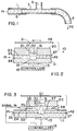
- Fig. 1 depicts an inlet conduit 1 supplying a liquid 5 at a pressure P1 to an outlet 2 at a pressure P2. If a T-fitting 3 is provided between the inlet and outlet, the liquid 5 will assume a certain level 6 within the open end of the fitting.
- P1/P2 the ratio of P1/P2 it can readily be demonstrated that an increased ratio causes the liquid level 6 to rise, and a decreased ratio causes the liquid level 6 to fall.
- Fig. 2 illustrates one AIP embodiment in accordance with the invention employing the principle illustrated in Fig. 1.
- Fig. 2 shows a printhead 10 including a substrate 11 of acoustically transmissive material provided with a recess 12 forming an acoustic lens.
- a known transducer 13 is connected to a known controller 15 for supplying a modulated RF voltage capable of establishing, as is known, focussed acoustic radiation 16, which comes to a focus at a focal plane 17 having a certain depth of focus.
- An apertured member 20, showing one aperture 21, is mounted over the substrate 11.
- a supply of liquid ink 22 is provided between the substrate 11 and the apertured member 20. The latter form a horizontal channel 24 filled with the ink 22, so that the ink contacts the upper side of the substrate 11 as well as the lower side of the apertured member 20.
- the member 20 can be any kind of a plate or wall member of a minimum thickness. It can be of the same or similar material and thickness as the perforated belt or web described in US-A-4,801,953, or the same or similar to the perforated membrane described in US-A-5,028,937 and copending application, Serial No. 07/634,248. Generally, the aperture 21 will have a height exceeding its diameter so that sufficient depth is available to move the liquid surface up and down within the aperture.
- An inlet 26 for the ink 22 is shown at the left, and an outlet 27 for the ink is shown at the right.
- the ink 22 will flow horizontally through the channel 24 and across the ejector and the ink will rise in the open channel or aperture 21 to a level 30 determined by the P1/P2 ratio.
- Media such as paper 28, can be caused to pass over the printhead 10.
- the transducer 13 is pulsed, if the ink level 30 is within the depth of focus of the focal plane 17 of the acoustic lens, an ink droplet 31 will be ejected upward to deposit on the media 28.
- Fig. 3 illustrates an AIP for the single lens case.
- Ink 20 from inlet 26 at pressure P1 is flowed through the channel 24 to outlet 27 at pressure P2.
- These pressures are established by known means not shown.
- a known piezoelectric driver 35 with matching stub 36 at the left side is mounted over a second perforated plate 37.
- a terminator 38 for a pressure pulse to avoid reflections is mounted at the right side of the lens.
- the terminator is of a well-known type as described in US-A-4,746,929 entitled "Travelling Wave Droplet Generator For An Ink Jet Printer".
- An advantage is that switching is not needed at the acoustic transducer 13, and the controller 15 can be connected as shown to driver 35.
- the impedance is very high and thus proper matching may be difficult. Without the necessity of switching at the transducer 13, we can easily connect several transducers 13 in parallel and thereby reduce the impedance level.
- Fig. 4 depicts a single lens system similar to that of Fig. 3 wherein the secondary pressure pulse is suppled in the form of a thermal pulse by a known heating element also located above the flowing ink stream 22.
- the heating element, designated 40 is the same or similar to that used in a known thermal ink jet, and when pulsed induces a thermal pulse into the liquid path. This in turn induces a pressure pulse which, as in the Fig. 3 embodiment, will serve to raise the liquid level 31 and switch ON the ejection of drops.
- Fig. 5 shows a further modification of the single lens device wherein the ink 22 flow in the channel 24 is horizontal under the member 20, but is supplied from below in a vertical right-angle direction from inlet 26 and similarly flows out via outlet 27.
- This provides a single channel 24 over the lens surface, and allows the piezo driver/stub 35, 36 to be located at one end of the channel 24 and the terminator 38 to be located at the opposite end.
- Fig. 6 shows the same system as in Fig. 5 but with the piezo driver replaced by a heating element similar to that shown in Fig. 4.
- Fig. 7 illustrates how the system is readily implemented into a lens array.
- One column 49 of two members of the double row is illustrated in an end view in Fig. 7(b) with two lens systems 50, 51.
- a common column inlet 54 and column outlet 55 for the common channel 56 supplies and removes the stream of ink flowed over the two lenses 50, 51.
- a common piezo driver 58 and terminator 59 are also in the channel 56.
- Fig. 7(c) shows the location of adjacent columns of double row ejectors, showing the staggered arrangement. Adjacent columns use the same reference numerals to designate corresponding parts with primes and double-primes added.
- Fig. 7(a) is a partial side view of the same arrangement taken from one end as shown in Fig. 7(c). In this arrangement, since each row can have a different timing for the RF pulses supplied to the transducers 52, 53, the rows can be addressed separately by choosing the timing of the pressure pulse to the piezo drivers 58, 58', 58''.
- Fig. 8 illustrates an AIP that can also be used in the Fig. 7 array with heating elements 40 substituted for the piezo drivers 58.
- the heating elements 40 can be located on the substrate 11 at the inlet channel 24.
- Fig. 9 illustrates a modification of Fig. 8 in the array configuration where a heating element 40' is placed separate from the substrate 11 and the overlay member 20 can be shaped appropriately to fit this arrangement of components.
Abstract
Description
- This invention relates to acoustic ink printing (AIP), and in particular to a novel construction for maintaining a fresh ink supply and for controlling switching of the AIP printheads between their ON and their OFF modes.
- AIP print elements operate by providing radiation pressure from a focussed acoustic wave to eject droplets from a free liquid surface. A transducer typically supplies a single burst or pulse of acoustic energy which is focussed at the free liquid surface and when of sufficient strength raises a mound on the liquid surface from which a single droplet is expelled which will deposit on print media overlying the free liquid surface. Printheads can be made of an array of such AIP print elements, each with its own transducer but operating with a common supply or pool of ink. For further details on constructions and the mechanisms involved, reference is made to commonly assigned US-A-4,719,480; US-A-4,751,530; US-A-4,801,953; and J. Appl. Phys. 55,3441 (1989).
- A problem that has arisen in connection with such AIP devices is that the elevation of the ink liquid surface varies during use. Performance of the device may be detrimentally affected when the liquid surface moves in and out of the focal plane of the acoustic wave from the transducer.
- US-A-5,028,937 describes an AIP with an ink pool covered with a perforated membrane, with bias pressure applied to the ink so that the ink menisci essentially remain within the focal plane of the acoustic beam.
- Another of the problems encountered on occasion with these types of printheads using an ink pool is the accumulation in the pool of dirt and debris from the ejector or the moving media above it.
- The previously-referenced US-A-4,801,953 describes one approach to provide a continuous supply of fresh ink at the ejector sites. This approach features transporting an apertured belt over the ejectors, with each aperture supplied with fresh ink to avoid the debris accumulation problem.
- Reference is also made to EP-A-000 000, corresponding to US application Serial No. 07/634,248, filed 26 December 1990, in which we disclose controlling the liquid ink surface within apertures in a membrane with an applied pressure signal to maintain the ink meniscus within the focal plane of the focused acoustic radiation or to effect ejection of individual ink droplets, the contents of which application are herein incorporated by reference.
- An object of the invention is to provide a fresh supply of ink at the ejector site or sites to mitigate the effect of contamination of the ink pool.
- A further object of the invention is to provide a fresh supply of ink at the ejector site or sites and to provide an additional means for controlling droplet ejection from the fresh supply of ink.
- Another object of the invention is an acoustic ink printhead providing dynamic control of the liquid level at the ejector sites together with maintaining a fresh supply of ink at such sites.
- The present invention provides an acoustic ink printer according to claim 1 of the appended claims.
- A feature of the present invention is to supply a horizontal component to the ink supply over the ejector sites but without requiring a moving belt. In accordance with this feature, a pressure differential is provided to supply a force with a horizontal component which moves the ink horizontally across the ejector site or sites.
- In accordance with a further aspect of the invention, located above the ejector sites is a fixed apertured member, with the ink droplets being ejected through the apertures. This offers the advantage of better control over the ejection direction because the system is designed so that the ink surface from which ejection occurs lies within the aperture or apertures, and thus the aperture sidewalls suppress the horizontal component of velocity of the flowing ink.
- Preferably, the printer includes means for flowing the ink in a continuous stream past the said aperature.
- Preferably, the printer further comprising means coupled to the ink for generating a secondary pressure field.
- Preferably, the ink flowing means comprises an inlet at a pressure P1 and an outlet at a pressure P2, where P1 > P2.
- Preferably, the inlet has a first portion that is laterally spaced from one side aperature, and the outlet has a first portion that is laterally spaced from the other side of the said aperature.
- Preferably, the inlet has a second portion transverse to the ink stream flow and connected to the inlet first portion.
- Preferably, the outlet has a second portion transverse to the ink stream flow and connected to the outlet first portion.
- The means for generating a secondary pressure field may comprise a piezo pulse driver with matching stub or heating element, and a pulse terminator.
- Preferably, fixed member comprises a member having a generally planar portion whose surface contacts the pool surface.
- The fixed member may have at least one row of aperatures, or at least two aperatures arranged in a row in series along the ink stream flow. The fixed member may have at least two adjacent rows of at least two aperatures each arranged in parallel along the ink stream flow.
- As still a further feature, a secondary pressure is provided which is used as a control mechanism for switching the ejector between its ON and OFF modes by dynamically controlling the free ink surface level in the aperture relative to the focal plane of the transducer. We have thus taken advantage of this shifting liquid ink surface level, which would normally be considered a disadvantage, and provided means for deliberately varying the liquid surface level as a way of controlling droplet ejection by the print element. In accordance with this aspect of the invention, we provide a construction for controlling the liquid level of the flowing ink above the transducer by means of a secondary pressure field. Preferably, the secondary pressure field is generated by acoustic or thermal means.
- In a preferred embodiment of the invention, an apertured member is mounted over the free surface of the liquid such that the liquid surface lies within an aperture to form an ejector site. The liquid is caused to flow. The aperture side walls suppress any horizontal component of velocity of the ink so that droplets are ejected substantially orthogonally to the ink surface. Preferably, the ink is caused to flow continuously past the apertures so that the ink surface from which ejection occurs can be maintained fresh and non-contaminated. We have found that the liquid level assumed by the ink in the aperture is determined by the ink pressures upstream and downstream of the aperture. We also know that droplet ejection does not occur unless the acoustic pressure at the surface exceeds a threshold value, which means that the liquid level for droplet ejection to occur, i.e., for the print element to be ON, must lie within a small range of distances from the focal plane of the transducer. Outside of that range, the print element will not eject droplets and remains OFF. It should be recalled that with such printheads involving a focused acoustic beam where the narrow waist coincides with the focal plane, the highest acoustic pressure will occur at the focal plane. By means of the secondary pressure field which provides a pressure pulse at the aperture, we can also selectively move the liquid level in and out of that narrow range and thus selectively switch the print element between its ON and OFF modes. In accordance with another aspect of the invention, the droplet ejection control can be used separately or together with the transducer as a way of controlling individual print elements, especially in an array configuration to form a printhead.
- The present invention will be better understood from the detailed description given herein below in conjunction with the accompanying drawings, which give by way of illustration only and not by limitation, preferred embodiments in accordance with the present invention.
- In the drawings:
- Fig. 1 is a schematic view of a hydraulic system to illustrate a principle underlying the invention;
- Fig. 2 is a side view of one form of AIP in accordance with the invention as a single lens or ejection site;
- Fig. 3 is a side view of another embodiment in accordance with the invention;
- Fig. 4 is a side view similar to Fig. 3 of a modification according to the invention;
- Fig. 5 is a side view of another modified form of AIP in accordance with the invention;
- Fig. 6 is a side view similar to Fig. 5 of a further modification;
- Fig. 7(a), 7(b), and 7(c) are side, end, and top views, respectively, of a lens array with multiple ejector sites; and
- Figs. 8 and 9 are side views of further modifications using heater elements to provide the pressure differential.
- The present invention provides novel AIP constructions and techniques for establishing and maintaining a fresh supply of ink at the ejectors, and also discloses for use alone or together with the above several novel approaches for dynamic control and regulation of the liquid level at the ejector site using the energy from acoustic pulses or pulsed heaters. The structures here disclosed can be used alone or together with many other AIP concepts including pressure equalization and matrix addressing. Many of the latter have already been fully described in the patents previously referenced and are intended to be included within the scope of the present invention. Thus, the present invention is not limited to, for example, specific kinds or geometries of transducers, specific transducers compositions, specific acoustic geometries or patterns, specific addressing techniques, or specific printhead configurations, such as single ejector, or matrix-configured ejector arrays, or pagewidth ejector arrays of the single row or multiple row staggered array configurations.
- While the examples that follow depict a variety of configurations employing various aspects of the present invention, this is not intended to be all-encompassing, and those skilled in this art will readily recognize that the principles disclosed herein are directly applicable to many of the types of AIPs disclosed in the referenced patents. It will also be observed that in many cases various components of the devices and systems described have been disclosed in relatively simple schematic form, as the details thereof are not essential to this invention and in any event can be found in the patents referenced in this specification as well as in those referenced in the referenced patents.
- As had been suggested in US-A-4,801,953, regular refreshing of the ink presented to the printhead is desirable. The operation of the AIP can cause contamination of a passive ink pool due to dirt and debris from the ambient or from erosion of the printhead and media. If the ink can be continuously circulated through filters and the like, the ink supply can be maintained clean and uncontaminated. Our approach is to flow a liquid sheet of clean ink over the array of lenses to replace the liquid at the ejector sites in a dynamic yet stable arrangement. A problem then is the inherent sidewise deflection of the droplets after ejection in the downstream direction of the ink flow. This is undesirable. Our invention offers a solution to that problem by suppressing the horizontal component of velocity of the flowing ink.
- In our preferred embodiments, we provide a flowing liquid ink sheet by establishing higher and lower inlet and outlet pressures, respectively. We have also found that the ratio of these two pressures, i.e., control of these two pressures, enables us to control the ink level at the ejector, within or without the focal plane of the acoustic lens. This provides an additional control mechanism for switching AIP printheads between their ON and OFF modes.
- The principle is illustrated in Fig. 1, which depicts an inlet conduit 1 supplying a
liquid 5 at a pressure P1 to anoutlet 2 at a pressure P2. If a T-fitting 3 is provided between the inlet and outlet, theliquid 5 will assume a certain level 6 within the open end of the fitting. By varying the ratio of P1/P2 it can readily be demonstrated that an increased ratio causes the liquid level 6 to rise, and a decreased ratio causes the liquid level 6 to fall. - Fig. 2 illustrates one AIP embodiment in accordance with the invention employing the principle illustrated in Fig. 1. Fig. 2 shows a
printhead 10 including asubstrate 11 of acoustically transmissive material provided with arecess 12 forming an acoustic lens. A knowntransducer 13 is connected to a knowncontroller 15 for supplying a modulated RF voltage capable of establishing, as is known, focussed acoustic radiation 16, which comes to a focus at a focal plane 17 having a certain depth of focus. Anapertured member 20, showing oneaperture 21, is mounted over thesubstrate 11. A supply ofliquid ink 22 is provided between thesubstrate 11 and theapertured member 20. The latter form ahorizontal channel 24 filled with theink 22, so that the ink contacts the upper side of thesubstrate 11 as well as the lower side of theapertured member 20. - The
member 20 can be any kind of a plate or wall member of a minimum thickness. It can be of the same or similar material and thickness as the perforated belt or web described in US-A-4,801,953, or the same or similar to the perforated membrane described in US-A-5,028,937 and copending application, Serial No. 07/634,248. Generally, theaperture 21 will have a height exceeding its diameter so that sufficient depth is available to move the liquid surface up and down within the aperture. - An
inlet 26 for theink 22 is shown at the left, and anoutlet 27 for the ink is shown at the right. We provide a pressure P1 at the inlet side and a pressure P2 at the outlet side by conventional means not shown, where P1 > P2. Under these circumstances, theink 22 will flow horizontally through thechannel 24 and across the ejector and the ink will rise in the open channel oraperture 21 to a level 30 determined by the P1/P2 ratio. Media, such aspaper 28, can be caused to pass over theprinthead 10. When thetransducer 13 is pulsed, if the ink level 30 is within the depth of focus of the focal plane 17 of the acoustic lens, anink droplet 31 will be ejected upward to deposit on themedia 28. If the ink level 30 happens to be outside the depth of focus of the focal plane 17, no ink droplet will be ejected. Thus, printing control can be exercised not only by thecontroller 15 driving thetransducer 13, but also by the means establishing the P1/P2 ratio. - The remaining figures in the drawing illustrate constructions to implement the pressure differential or ratio establishing means together with other droplet ejection control means. In all cases, the same reference numerals have been used to designate similar elements.
- Fig. 3 illustrates an AIP for the single lens case.
Ink 20 frominlet 26 at pressure P1 is flowed through thechannel 24 tooutlet 27 at pressure P2. These pressures are established by known means not shown. In addition, a knownpiezoelectric driver 35 with matchingstub 36 at the left side is mounted over a second perforated plate 37. Aterminator 38 for a pressure pulse to avoid reflections is mounted at the right side of the lens. The terminator is of a well-known type as described in US-A-4,746,929 entitled "Travelling Wave Droplet Generator For An Ink Jet Printer". The addition of the two additional ports for receiving thepiezo driver 35 andterminator 38 will enable, when the driver is pulsed, to induce a short pressure pulse which will traverse thechannel 22 and terminate at theterminator 38. Assuming the pressure ratio P1/P2 was such as to establish the liquid level in the open channel at level "1", the pressure pulse will raise the level from level "1" to level "2". If the acoustic lens is adjusted such that the focal plane is located as shown between levels "1" and "2", then a droplet will be ejected at the time that the level 30 of the liquid passes through the focal plane. By properly timing the RF pulses to theinput transducer 13, which is easily done, we can use the pressure pulse from thedriver 35 to switch the lens between its OFF and ON states. An advantage is that switching is not needed at theacoustic transducer 13, and thecontroller 15 can be connected as shown todriver 35. In small transducers, the impedance is very high and thus proper matching may be difficult. Without the necessity of switching at thetransducer 13, we can easily connectseveral transducers 13 in parallel and thereby reduce the impedance level. - Fig. 4 depicts a single lens system similar to that of Fig. 3 wherein the secondary pressure pulse is suppled in the form of a thermal pulse by a known heating element also located above the flowing
ink stream 22. The heating element, designated 40, is the same or similar to that used in a known thermal ink jet, and when pulsed induces a thermal pulse into the liquid path. This in turn induces a pressure pulse which, as in the Fig. 3 embodiment, will serve to raise theliquid level 31 and switch ON the ejection of drops. - Fig. 5 shows a further modification of the single lens device wherein the
ink 22 flow in thechannel 24 is horizontal under themember 20, but is supplied from below in a vertical right-angle direction frominlet 26 and similarly flows out viaoutlet 27. This provides asingle channel 24 over the lens surface, and allows the piezo driver/stub channel 24 and theterminator 38 to be located at the opposite end. - Fig. 6 shows the same system as in Fig. 5 but with the piezo driver replaced by a heating element similar to that shown in Fig. 4.
- Fig. 7 illustrates how the system is readily implemented into a lens array. In this case, we chose to illustrate the lens array with multiple staggered rows, two of which are shown in Figs. 7(a) and 7(c), but it will be appreciated that one row or three rows or more than three rows are within the scope of this invention.
- One
column 49 of two members of the double row is illustrated in an end view in Fig. 7(b) with twolens systems common column inlet 54 andcolumn outlet 55 for thecommon channel 56 supplies and removes the stream of ink flowed over the twolenses piezo driver 58 andterminator 59 are also in thechannel 56. - The top view in Fig. 7(c) shows the location of adjacent columns of double row ejectors, showing the staggered arrangement. Adjacent columns use the same reference numerals to designate corresponding parts with primes and double-primes added. Fig. 7(a) is a partial side view of the same arrangement taken from one end as shown in Fig. 7(c). In this arrangement, since each row can have a different timing for the RF pulses supplied to the
transducers piezo drivers 58, 58', 58''. - Fig. 8 illustrates an AIP that can also be used in the Fig. 7 array with
heating elements 40 substituted for thepiezo drivers 58. Theheating elements 40 can be located on thesubstrate 11 at theinlet channel 24. - Fig. 9 illustrates a modification of Fig. 8 in the array configuration where a heating element 40' is placed separate from the
substrate 11 and theoverlay member 20 can be shaped appropriately to fit this arrangement of components. - The components establishing the pressures P1 and P2 at the channel inlet and outlet, respectively, have not been shown as they employ conventional fluid control and regulating members readily available as off-the-shelf components from plumbing supply houses. They are merely shown in block schematic form in Fig. 6 labelled as
pressure control elements - An example of a suitable pressure ratio, which is not meant to be limiting, now follows. Assuming that the overlay member thickness is about 0.3 mm, and the liquid level "1" is to be located about 0.3 mm above the bottom surface of the
member 20, the pressure differential (P₁-P₂) should be in the range of 0.01 to 0.1 mbars, and the ink flow stream velocity over the ejector would be in the range of about 1 to 10 ml/sec. These values are not critical. - While the invention has been described and illustrated in connection with preferred embodiments, many variations and modifications as will be evident to those skilled in this art may be made therein without departing from the scope of the invention, and the invention as set forth in the appended claims is thus not to be limited to the precise details of construction set forth above as such variations and modifications are intended to be included within the scope of the appended claims.
Claims (10)
- An acoustic ink printer comprising:(a) a pool of liquid ink having a surface,(b) an apertured member having at least one aperture extending over the ink pool such that a portion of the ink surface that is free lies substantially inside the said aperature,(c) means for focussing acoustic radiation at the free ink surface within said aperature whereby when the ink surface lies within the focal plane of the acoustic radiation, individual droplets of ink will be ejected from the free ink surface inside the aperature.
- A printer according to claim 1, further comprising:
means for maintaining a fresh supply of ink inside the said aperature. - A printer according to claim 1 or claim 2, further comprising:
means for varying the pressure in the ink pool for varying the position of the ink surface within the aperature. - A printer according to claim 1, 2 or 3, further comprising:
means for establishing a lateral pressure differential in the ink pool for causing the ink to flow past the aperature. - The acoustic ink printer of claim 4, wherein the pressure differential is such as to cause the ink to assume a determined level within the aperature.
- The acoustic ink printer according to any of the preceding claims, wherein the aperatured member is fixed.
- The acoustic ink printer according to any of the preceding claims, further comprises means for selectively varying the pressure differential to vary the level of the free ink surface inside the aperature to selective move the free ink surface in and out of the focal plane of the acoustic radiation.
- The acoustic ink printer of claim 4, further comprising an inlet for ink at a pressure P1 on one side of said aperature and an outlet for ink at a pressure P2 on the opposite side of said aperature, means for controlling the inlet pressure P1 for establishing the pressure differential.
- The acoustic ink printer of claim 4, further comprising an inlet for ink at a pressure P1 on one side of said aperature and an outlet for ink at a pressure P2 on the opposite side of said aperature, means for controlling the outlet pressure P2 for establishing the pressure differential.
- An acoustic printhead for ejecting droplets of ink in response to acoustic or heat pulses, comprising:(a) a pool of ink having a free surface,(b) an aperatured member overlying the ink free surface,(c)means for maintaining a continuous flow of ink across the aperatures,(d) means for generating a focussed acoustic wave at the free ink surface to cause the selective ejection of ink droplets from the aperatures when the free ink surface lies within the focal plane of the acoustic wave,(e) means for applying a secondary pressure field to the ink pool for selectively moving the free ink surface level in and out of the focal plane.
Applications Claiming Priority (2)
| Application Number | Priority Date | Filing Date | Title |
|---|---|---|---|
| US81572991A | 1991-12-30 | 1991-12-30 | |
| US815729 | 1991-12-30 |
Publications (3)
| Publication Number | Publication Date |
|---|---|
| EP0550148A2 true EP0550148A2 (en) | 1993-07-07 |
| EP0550148A3 EP0550148A3 (en) | 1993-11-18 |
| EP0550148B1 EP0550148B1 (en) | 1996-10-09 |
Family
ID=25218675
Family Applications (1)
| Application Number | Title | Priority Date | Filing Date |
|---|---|---|---|
| EP19920310809 Expired - Lifetime EP0550148B1 (en) | 1991-12-30 | 1992-11-26 | Acoustic ink printhead with apertured member and flowing ink |
Country Status (3)
| Country | Link |
|---|---|
| EP (1) | EP0550148B1 (en) |
| JP (1) | JPH05246028A (en) |
| DE (1) | DE69214418T2 (en) |
Cited By (10)
| Publication number | Priority date | Publication date | Assignee | Title |
|---|---|---|---|---|
| EP0621135A1 (en) * | 1993-04-23 | 1994-10-26 | Brother Kogyo Kabushiki Kaisha | Ink jet apparatus |
| WO1995010415A1 (en) * | 1993-10-08 | 1995-04-20 | Gec-Marconi Limited | Fluid dispenser |
| EP0683048A2 (en) * | 1994-05-18 | 1995-11-22 | Xerox Corporation | Lithographically defined ejection units |
| WO1996032277A1 (en) * | 1995-04-12 | 1996-10-17 | Eastman Kodak Company | Coincident drop selection, drop separation printing method and system |
| WO1996032279A1 (en) * | 1995-04-12 | 1996-10-17 | Eastman Kodak Company | A liquid ink printing apparatus and system |
| EP0739732A1 (en) * | 1995-04-27 | 1996-10-30 | Xerox Corporation | Variable focal length acoustic ink printhead |
| EP0869001A2 (en) * | 1997-04-03 | 1998-10-07 | Mitsubishi Denki Kabushiki Kaisha | Liquid ejector and printer apparatus |
| US5880759A (en) * | 1995-04-12 | 1999-03-09 | Eastman Kodak Company | Liquid ink printing apparatus and system |
| WO1999056958A1 (en) * | 1998-05-06 | 1999-11-11 | Eastman Kodak Company | Ink jet printhead with pressure concentrater |
| WO2011070079A1 (en) * | 2009-12-10 | 2011-06-16 | Schmid Technology Gmbh | Device and method for transferring a printing substance from a printing substance carrier to a substrate |
Families Citing this family (1)
| Publication number | Priority date | Publication date | Assignee | Title |
|---|---|---|---|---|
| JP4686387B2 (en) * | 2006-03-17 | 2011-05-25 | 株式会社東芝 | Inkjet head, inkjet ejection apparatus, inkjet recording apparatus, and inkjet ejection method |
Citations (7)
| Publication number | Priority date | Publication date | Assignee | Title |
|---|---|---|---|---|
| US4106032A (en) * | 1974-09-26 | 1978-08-08 | Matsushita Electric Industrial Co., Limited | Apparatus for applying liquid droplets to a surface by using a high speed laminar air flow to accelerate the same |
| US4308547A (en) * | 1978-04-13 | 1981-12-29 | Recognition Equipment Incorporated | Liquid drop emitter |
| JPS60204364A (en) * | 1984-03-30 | 1985-10-15 | Canon Inc | Liquid jet recording unit |
| US4728969A (en) * | 1986-07-11 | 1988-03-01 | Tektronix, Inc. | Air assisted ink jet head with single compartment ink chamber |
| US4764780A (en) * | 1985-12-25 | 1988-08-16 | Matsushita Electric Industrial Co., Ltd. | Ink ejection recording apparatus having means for equalizing the static ink pressures of a plurality of ink nozzles arranged at different heights |
| US5028937A (en) * | 1989-05-30 | 1991-07-02 | Xerox Corporation | Perforated membranes for liquid contronlin acoustic ink printing |
| EP0493102A1 (en) * | 1990-12-26 | 1992-07-01 | Xerox Corporation | Acoustic ink printing |
-
1992
- 1992-11-26 DE DE1992614418 patent/DE69214418T2/en not_active Expired - Fee Related
- 1992-11-26 EP EP19920310809 patent/EP0550148B1/en not_active Expired - Lifetime
- 1992-12-14 JP JP35351392A patent/JPH05246028A/en not_active Withdrawn
Patent Citations (7)
| Publication number | Priority date | Publication date | Assignee | Title |
|---|---|---|---|---|
| US4106032A (en) * | 1974-09-26 | 1978-08-08 | Matsushita Electric Industrial Co., Limited | Apparatus for applying liquid droplets to a surface by using a high speed laminar air flow to accelerate the same |
| US4308547A (en) * | 1978-04-13 | 1981-12-29 | Recognition Equipment Incorporated | Liquid drop emitter |
| JPS60204364A (en) * | 1984-03-30 | 1985-10-15 | Canon Inc | Liquid jet recording unit |
| US4764780A (en) * | 1985-12-25 | 1988-08-16 | Matsushita Electric Industrial Co., Ltd. | Ink ejection recording apparatus having means for equalizing the static ink pressures of a plurality of ink nozzles arranged at different heights |
| US4728969A (en) * | 1986-07-11 | 1988-03-01 | Tektronix, Inc. | Air assisted ink jet head with single compartment ink chamber |
| US5028937A (en) * | 1989-05-30 | 1991-07-02 | Xerox Corporation | Perforated membranes for liquid contronlin acoustic ink printing |
| EP0493102A1 (en) * | 1990-12-26 | 1992-07-01 | Xerox Corporation | Acoustic ink printing |
Non-Patent Citations (1)
| Title |
|---|
| PATENT ABSTRACTS OF JAPAN vol. 10, no. 55 (M-458)5 February 1986 & JP-A-60 204 364 ( CANON ) 15 October 1985 * |
Cited By (16)
| Publication number | Priority date | Publication date | Assignee | Title |
|---|---|---|---|---|
| US5587727A (en) * | 1993-04-23 | 1996-12-24 | Brother Kogyo Kabushiki Kaisha | Ink jet apparatus using pressure wave intersection to eject ink droplets |
| EP0621135A1 (en) * | 1993-04-23 | 1994-10-26 | Brother Kogyo Kabushiki Kaisha | Ink jet apparatus |
| WO1995010415A1 (en) * | 1993-10-08 | 1995-04-20 | Gec-Marconi Limited | Fluid dispenser |
| EP0683048A2 (en) * | 1994-05-18 | 1995-11-22 | Xerox Corporation | Lithographically defined ejection units |
| EP0683048A3 (en) * | 1994-05-18 | 1996-06-26 | Xerox Corp | Lithographically defined ejection units. |
| US5880759A (en) * | 1995-04-12 | 1999-03-09 | Eastman Kodak Company | Liquid ink printing apparatus and system |
| WO1996032277A1 (en) * | 1995-04-12 | 1996-10-17 | Eastman Kodak Company | Coincident drop selection, drop separation printing method and system |
| WO1996032279A1 (en) * | 1995-04-12 | 1996-10-17 | Eastman Kodak Company | A liquid ink printing apparatus and system |
| EP0739732A1 (en) * | 1995-04-27 | 1996-10-30 | Xerox Corporation | Variable focal length acoustic ink printhead |
| EP0869001A2 (en) * | 1997-04-03 | 1998-10-07 | Mitsubishi Denki Kabushiki Kaisha | Liquid ejector and printer apparatus |
| EP0869001A3 (en) * | 1997-04-03 | 1999-04-14 | Mitsubishi Denki Kabushiki Kaisha | Liquid ejector and printer apparatus |
| US6154235A (en) * | 1997-04-03 | 2000-11-28 | Mitsubishi Denki Kabushiki Kaisha | Acoustic liquid ejector and printer apparatus incorporating the ejector |
| WO1999056958A1 (en) * | 1998-05-06 | 1999-11-11 | Eastman Kodak Company | Ink jet printhead with pressure concentrater |
| GB2351042A (en) * | 1998-05-06 | 2000-12-20 | Eastman Kodak Co | Ink jet printhead with pressure concentrater |
| GB2351042B (en) * | 1998-05-06 | 2002-02-20 | Eastman Kodak Co | An ink jet printhead unit |
| WO2011070079A1 (en) * | 2009-12-10 | 2011-06-16 | Schmid Technology Gmbh | Device and method for transferring a printing substance from a printing substance carrier to a substrate |
Also Published As
| Publication number | Publication date |
|---|---|
| EP0550148A3 (en) | 1993-11-18 |
| DE69214418D1 (en) | 1996-11-14 |
| EP0550148B1 (en) | 1996-10-09 |
| JPH05246028A (en) | 1993-09-24 |
| DE69214418T2 (en) | 1997-03-06 |
Similar Documents
| Publication | Publication Date | Title |
|---|---|---|
| JP3406694B2 (en) | Inkjet print head | |
| US6513903B2 (en) | Ink jet print head with capillary flow cleaning | |
| DE69736992T2 (en) | Ink jet recording head | |
| KR20190002321A (en) | Liquid ejection head and liquid ejection apparatus | |
| EP3421241B1 (en) | Liquid ejection head and liquid ejection apparatus | |
| JP4467858B2 (en) | Droplet deposition method and apparatus | |
| EP0550148B1 (en) | Acoustic ink printhead with apertured member and flowing ink | |
| JPS62263062A (en) | Printer head for ink jet printer | |
| KR101665750B1 (en) | Fluid ejection device | |
| JPH10157110A (en) | Thermal ink jet printing system | |
| US20080239007A1 (en) | Print head | |
| US8636349B2 (en) | Liquid ejection head and liquid ejection apparatus | |
| US20210291547A1 (en) | Fluidic ejection dies with enclosed cross-channels | |
| EP3429856B1 (en) | Fluid ejection device with a portioning wall | |
| JP2002160368A (en) | Print head | |
| JP4680499B2 (en) | Droplet deposition device | |
| EP1216834B1 (en) | Ink jet printing using drop-on-demand techniques for continuous tone printing | |
| JP2020104312A (en) | Liquid discharge head, liquid discharge device and liquid supply method | |
| CN111993791B (en) | Ink jet device and system with enclosed dual feed drop ejector | |
| EP0771664B1 (en) | Ink cartridge for ink jet printer | |
| TWI485071B (en) | Electrostatic liquid-ejection actuation mechanism | |
| US10864727B2 (en) | Liquid discharge head and liquid discharge apparatus provided with the same | |
| JPH03292145A (en) | Ink-jet recording device | |
| US20140307033A1 (en) | Pre-heating liquid ejected from a liquid dispenser | |
| JP4768351B2 (en) | Ink jet recording head and ink jet recording apparatus including the same |
Legal Events
| Date | Code | Title | Description |
|---|---|---|---|
| PUAI | Public reference made under article 153(3) epc to a published international application that has entered the european phase |
Free format text: ORIGINAL CODE: 0009012 |
|
| AK | Designated contracting states |
Kind code of ref document: A2 Designated state(s): DE FR GB |
|
| PUAL | Search report despatched |
Free format text: ORIGINAL CODE: 0009013 |
|
| AK | Designated contracting states |
Kind code of ref document: A3 Designated state(s): DE FR GB |
|
| 17P | Request for examination filed |
Effective date: 19940506 |
|
| 17Q | First examination report despatched |
Effective date: 19940926 |
|
| GRAH | Despatch of communication of intention to grant a patent |
Free format text: ORIGINAL CODE: EPIDOS IGRA |
|
| GRAH | Despatch of communication of intention to grant a patent |
Free format text: ORIGINAL CODE: EPIDOS IGRA |
|
| GRAA | (expected) grant |
Free format text: ORIGINAL CODE: 0009210 |
|
| AK | Designated contracting states |
Kind code of ref document: B1 Designated state(s): DE FR GB |
|
| REF | Corresponds to: |
Ref document number: 69214418 Country of ref document: DE Date of ref document: 19961114 |
|
| ET | Fr: translation filed | ||
| PLBE | No opposition filed within time limit |
Free format text: ORIGINAL CODE: 0009261 |
|
| STAA | Information on the status of an ep patent application or granted ep patent |
Free format text: STATUS: NO OPPOSITION FILED WITHIN TIME LIMIT |
|
| 26N | No opposition filed | ||
| PGFP | Annual fee paid to national office [announced via postgrant information from national office to epo] |
Ref country code: FR Payment date: 20001110 Year of fee payment: 9 |
|
| PGFP | Annual fee paid to national office [announced via postgrant information from national office to epo] |
Ref country code: DE Payment date: 20001120 Year of fee payment: 9 |
|
| PGFP | Annual fee paid to national office [announced via postgrant information from national office to epo] |
Ref country code: GB Payment date: 20001122 Year of fee payment: 9 |
|
| PG25 | Lapsed in a contracting state [announced via postgrant information from national office to epo] |
Ref country code: GB Free format text: LAPSE BECAUSE OF NON-PAYMENT OF DUE FEES Effective date: 20011126 |
|
| REG | Reference to a national code |
Ref country code: GB Ref legal event code: IF02 |
|
| PG25 | Lapsed in a contracting state [announced via postgrant information from national office to epo] |
Ref country code: DE Free format text: LAPSE BECAUSE OF NON-PAYMENT OF DUE FEES Effective date: 20020702 |
|
| GBPC | Gb: european patent ceased through non-payment of renewal fee |
Effective date: 20011126 |
|
| PG25 | Lapsed in a contracting state [announced via postgrant information from national office to epo] |
Ref country code: FR Free format text: LAPSE BECAUSE OF NON-PAYMENT OF DUE FEES Effective date: 20020730 |
|
| REG | Reference to a national code |
Ref country code: FR Ref legal event code: ST |
|
| REG | Reference to a national code |
Ref country code: FR Ref legal event code: ST |