EP0551601A1 - Method and device for feeding particularly folded printed products to a further processing station - Google Patents
Method and device for feeding particularly folded printed products to a further processing station Download PDFInfo
- Publication number
- EP0551601A1 EP0551601A1 EP92120375A EP92120375A EP0551601A1 EP 0551601 A1 EP0551601 A1 EP 0551601A1 EP 92120375 A EP92120375 A EP 92120375A EP 92120375 A EP92120375 A EP 92120375A EP 0551601 A1 EP0551601 A1 EP 0551601A1
- Authority
- EP
- European Patent Office
- Prior art keywords
- printed products
- conveying
- intermediate stack
- conveyor
- conveying device
- Prior art date
- Legal status (The legal status is an assumption and is not a legal conclusion. Google has not performed a legal analysis and makes no representation as to the accuracy of the status listed.)
- Granted
Links
Images


Classifications
-
- B—PERFORMING OPERATIONS; TRANSPORTING
- B41—PRINTING; LINING MACHINES; TYPEWRITERS; STAMPS
- B41F—PRINTING MACHINES OR PRESSES
- B41F13/00—Common details of rotary presses or machines
- B41F13/54—Auxiliary folding, cutting, collecting or depositing of sheets or webs
-
- B—PERFORMING OPERATIONS; TRANSPORTING
- B65—CONVEYING; PACKING; STORING; HANDLING THIN OR FILAMENTARY MATERIAL
- B65H—HANDLING THIN OR FILAMENTARY MATERIAL, e.g. SHEETS, WEBS, CABLES
- B65H29/00—Delivering or advancing articles from machines; Advancing articles to or into piles
- B65H29/66—Advancing articles in overlapping streams
- B65H29/669—Advancing articles in overlapping streams ending an overlapping stream
-
- B—PERFORMING OPERATIONS; TRANSPORTING
- B65—CONVEYING; PACKING; STORING; HANDLING THIN OR FILAMENTARY MATERIAL
- B65H—HANDLING THIN OR FILAMENTARY MATERIAL, e.g. SHEETS, WEBS, CABLES
- B65H29/00—Delivering or advancing articles from machines; Advancing articles to or into piles
- B65H29/003—Delivering or advancing articles from machines; Advancing articles to or into piles by grippers
-
- B—PERFORMING OPERATIONS; TRANSPORTING
- B65—CONVEYING; PACKING; STORING; HANDLING THIN OR FILAMENTARY MATERIAL
- B65H—HANDLING THIN OR FILAMENTARY MATERIAL, e.g. SHEETS, WEBS, CABLES
- B65H29/00—Delivering or advancing articles from machines; Advancing articles to or into piles
- B65H29/24—Delivering or advancing articles from machines; Advancing articles to or into piles by air blast or suction apparatus
-
- B—PERFORMING OPERATIONS; TRANSPORTING
- B65—CONVEYING; PACKING; STORING; HANDLING THIN OR FILAMENTARY MATERIAL
- B65H—HANDLING THIN OR FILAMENTARY MATERIAL, e.g. SHEETS, WEBS, CABLES
- B65H83/00—Combinations of piling and depiling operations, e.g. performed simultaneously, of interest apart from the single operation of piling or depiling as such
- B65H83/02—Combinations of piling and depiling operations, e.g. performed simultaneously, of interest apart from the single operation of piling or depiling as such performed on the same pile or stack
-
- B—PERFORMING OPERATIONS; TRANSPORTING
- B65—CONVEYING; PACKING; STORING; HANDLING THIN OR FILAMENTARY MATERIAL
- B65H—HANDLING THIN OR FILAMENTARY MATERIAL, e.g. SHEETS, WEBS, CABLES
- B65H2301/00—Handling processes for sheets or webs
- B65H2301/40—Type of handling process
- B65H2301/42—Piling, depiling, handling piles
- B65H2301/421—Forming a pile
- B65H2301/4212—Forming a pile of articles substantially horizontal
- B65H2301/42122—Forming a pile of articles substantially horizontal by introducing articles from under the pile
-
- B—PERFORMING OPERATIONS; TRANSPORTING
- B65—CONVEYING; PACKING; STORING; HANDLING THIN OR FILAMENTARY MATERIAL
- B65H—HANDLING THIN OR FILAMENTARY MATERIAL, e.g. SHEETS, WEBS, CABLES
- B65H2301/00—Handling processes for sheets or webs
- B65H2301/40—Type of handling process
- B65H2301/42—Piling, depiling, handling piles
- B65H2301/421—Forming a pile
- B65H2301/4213—Forming a pile of a limited number of articles, e.g. buffering, forming bundles
-
- B—PERFORMING OPERATIONS; TRANSPORTING
- B65—CONVEYING; PACKING; STORING; HANDLING THIN OR FILAMENTARY MATERIAL
- B65H—HANDLING THIN OR FILAMENTARY MATERIAL, e.g. SHEETS, WEBS, CABLES
- B65H2301/00—Handling processes for sheets or webs
- B65H2301/40—Type of handling process
- B65H2301/44—Moving, forwarding, guiding material
- B65H2301/447—Moving, forwarding, guiding material transferring material between transport devices
- B65H2301/4471—Grippers, e.g. moved in paths enclosing an area
- B65H2301/44712—Grippers, e.g. moved in paths enclosing an area carried by chains or bands
-
- B—PERFORMING OPERATIONS; TRANSPORTING
- B65—CONVEYING; PACKING; STORING; HANDLING THIN OR FILAMENTARY MATERIAL
- B65H—HANDLING THIN OR FILAMENTARY MATERIAL, e.g. SHEETS, WEBS, CABLES
- B65H2301/00—Handling processes for sheets or webs
- B65H2301/40—Type of handling process
- B65H2301/44—Moving, forwarding, guiding material
- B65H2301/447—Moving, forwarding, guiding material transferring material between transport devices
- B65H2301/4472—Suction grippers, e.g. moved in paths enclosing an area
-
- B—PERFORMING OPERATIONS; TRANSPORTING
- B65—CONVEYING; PACKING; STORING; HANDLING THIN OR FILAMENTARY MATERIAL
- B65H—HANDLING THIN OR FILAMENTARY MATERIAL, e.g. SHEETS, WEBS, CABLES
- B65H2301/00—Handling processes for sheets or webs
- B65H2301/40—Type of handling process
- B65H2301/44—Moving, forwarding, guiding material
- B65H2301/447—Moving, forwarding, guiding material transferring material between transport devices
- B65H2301/4473—Belts, endless moving elements on which the material is in surface contact
- B65H2301/44732—Belts, endless moving elements on which the material is in surface contact transporting articles in overlapping stream
-
- B—PERFORMING OPERATIONS; TRANSPORTING
- B65—CONVEYING; PACKING; STORING; HANDLING THIN OR FILAMENTARY MATERIAL
- B65H—HANDLING THIN OR FILAMENTARY MATERIAL, e.g. SHEETS, WEBS, CABLES
- B65H2301/00—Handling processes for sheets or webs
- B65H2301/40—Type of handling process
- B65H2301/44—Moving, forwarding, guiding material
- B65H2301/447—Moving, forwarding, guiding material transferring material between transport devices
- B65H2301/4474—Pair of cooperating moving elements as rollers, belts forming nip into which material is transported
-
- B—PERFORMING OPERATIONS; TRANSPORTING
- B65—CONVEYING; PACKING; STORING; HANDLING THIN OR FILAMENTARY MATERIAL
- B65H—HANDLING THIN OR FILAMENTARY MATERIAL, e.g. SHEETS, WEBS, CABLES
- B65H2405/00—Parts for holding the handled material
- B65H2405/50—Gripping means
- B65H2405/58—Means for achieving gripping/releasing operation
- B65H2405/583—Details of gripper orientation
- B65H2405/5832—Details of gripper orientation and varying its orientation after gripping
Landscapes
- Mechanical Engineering (AREA)
- Engineering & Computer Science (AREA)
- Feeding Of Articles By Means Other Than Belts Or Rollers (AREA)
- Folding Of Thin Sheet-Like Materials, Special Discharging Devices, And Others (AREA)
- Separation, Sorting, Adjustment, Or Bending Of Sheets To Be Conveyed (AREA)
- Discharge By Other Means (AREA)
- Sheets, Magazines, And Separation Thereof (AREA)
- Stringed Musical Instruments (AREA)
- Ultra Sonic Daignosis Equipment (AREA)
- Diaphragms For Electromechanical Transducers (AREA)
- Delivering By Means Of Belts And Rollers (AREA)
- Coloring (AREA)
- Making Paper Articles (AREA)
Abstract
Description
Die vorliegende Erfindung betrifft ein Verfahren bzw. eine Vorrichtung zum Zubringen von vorzugsweise gefalteten Druckereierzeugnissen zu einer Weiterverarbeitungsstelle gemäss Oberbegriff des Anspruches 1 bzw. des Anspruches 6.The present invention relates to a method and a device for feeding preferably folded printed products to a further processing point according to the preamble of claim 1 and claim 6.
Bei der in der CH-A-630 583 und der entsprechenden US-A-4,320,894 beschriebenen Vorrichtung dieser Art werden die zugeführten Druckereierzeugnisse im Uebergabebereich durch den Zuförderer direkt in die vorbeilaufenden offenen Greifer des Wegförderers eingeschoben. Um ein richtiges Erfassen der Druckereierzeugnisse sicherzustellen, verläuft im Uebergabebereich der Druckereierzeugnisse die Förderrichtung des Wegförderers von unten nach oben und quer zur Förderrichtung der zugeführten Druckereierzeugnisse. Durch diese Massnahme können zwar geringfügige Unregelmässigkeiten in den Abständen aufeinanderfolgender Druckereierzeugnisse im Schuppenstrom aufgefangen werden, doch führt ein zu grosser Abstand zwischen zwei Druckereierzeugnissen innerhalb der zugeführten Schuppenformation dazu, dass gewisse Produkte zu spät zum Uebergabebereich gelangen und damit den zugeordneten Greifer verpassen, der dann leer zur Weiterverarbeitungsstelle gelangt. Der nachfolgende Greifer nimmt dann neben dem ihm zugeordneten Druckereierzeugnis auch noch dasjenige Erzeugnis mit, das vom vorauslaufenden Greifer nicht hat mitgenommen werden können. Es ist somit offensichtlich, dass sich ein solcher unregelmässiger Anfall von Druckereierzeugnissen an der nachgeschalteten Weiterverarbeitungsstelle nachteilig auswirken kann.In the device of this type described in CH-A-630 583 and the corresponding US-A-4,320,894, the supplied printed products in the transfer area are inserted directly into the passing open grippers of the conveyor by the feed conveyor. In order to ensure that the printed products are correctly grasped, the conveying direction of the away conveyor runs in the transfer area of the printed products from bottom to top and transversely to the conveying direction of the supplied printed products. Although this measure can compensate for slight irregularities in the spacing of successive printed products in the shingled stream, too great a distance between two printed products within the supplied shingled formation means that certain products arrive too late in the transfer area and thus miss the assigned gripper, which is then empty reached the processing station. In addition to the print product assigned to it, the subsequent gripper then also picks up the product that the preceding gripper could not take with it. It is therefore obvious that such an irregular occurrence of printed matter occurs at the downstream processing point can have an adverse effect.
Aus der EP-A-0 368 009 (und der entsprechenden US-A-5,042,792) ist es weiter bekannt, Druckereierzeugnisse, die paarweise übereinanderliegend in einer Schuppenformation zugefördert werden, in der jedes Erzeugnispaar auf dem nachfolgenden Erzeugnispaar aufliegt, gegen einen Anschlag zu fördern, dann im Bereich der vorlaufenden Kante durch ein Saugorgan zu erfassen und anzuheben, um das entsprechende Druckereierzeungis in den Wirkbereich von umlaufenden Mitnehmerelementen zu bringen, die die vorlaufenden Kanten der Druckereierzeugnisse weiter in den Förderbereich eines Wegförderers anheben, der aus zwei zusammenwirkenden Bandförderern gebildet ist. Mit dieser bekannten Vorrichtung lassen sich die in der zugeführten Schuppenformation übereinanderliegenden Druckereierzeugnisse voneinander ablösen und zu einer neuen Schuppenformation formieren, in der sich alle Erzeugnisse nur teilweise überlappen und sich nicht mehr vollständig überdecken.From EP-A-0 368 009 (and the corresponding US-A-5,042,792) it is further known to convey printed products which are fed in pairs one above the other in a scale formation in which each pair of products rests on the subsequent pair of products against a stop , then to be grasped and raised in the area of the leading edge by a suction element in order to bring the corresponding printed product into the effective area of rotating driver elements, which further raise the leading edges of the printed products into the conveying area of a conveyor which is formed from two interacting belt conveyors. With this known device, the printed products lying one above the other in the supplied flake formation can be detached from one another and formed into a new flake formation in which all the products only partially overlap and no longer completely overlap.
Doch ist es auch bei dieser Vorrichtung wichtig, dass die Pakete von Druckereierzeugnissen in der zugeführten Schuppenformation im wesentlichen gleiche Abstände voneinander haben, damit ein ungestörtes Separieren der sich vollständig überdeckenden Druckereierzeugnisse möglich ist.However, it is also important with this device that the packages of printed products in the supplied scale formation have essentially the same distances from one another, so that an undisturbed separation of the completely overlapping printed products is possible.
Der vorliegenden Erfindung liegt nun die Aufgabe zugrunde, ein Verfahren sowie eine Vorrichtung der eingangs genannten Art zu schaffen, das bzw. die es erlaubt, die Druckereierzeugnissen unabhängig von der Qualität der zugeführten Schuppenformation in der gewünschten Folge einer Weiterverarbeitungsstelle zuzuführen.The present invention is based on the object of creating a method and a device of the type mentioned at the outset which allow the printed products to be fed to a further processing point in the desired sequence, regardless of the quality of the flake formation supplied.
Diese Aufgabe wird erfindungsgemäss durch die Merkmale des kennzeichnenden Teils des Anspruches 1 bzw. des Anspruches 6 gelöst.This object is achieved according to the invention by the features of the characterizing part of claim 1 and of
Dadurch, dass die zugeführten Druckereierzeugnisse zuerst in einen Zwischenstapel eingeschoben werden, dem sie durch die Saugeranordnung von oben entnommen und der zweiten Fördereinrichtung zugeführt werden, wird die Zuführung der Druckereierzeugnisse zur zweiten Fördereinrichtung von der Zufuhr der Druckereierzeugnisse durch die erste Fördereinrichtung entkoppelt. Dies bedeutet, dass zu grosse oder zu kleine Abstände zwischen aufeinanderfolgenden Druckereierzeugnissen und auch fehlende Druckereierzeugnisse im zugeführten Schuppenstrom die richtige Zuführung von Druckereierzeugnissen zur zweiten Fördereinrichtung nicht mehr beeinflussen. Derartige Unregelmässigkeiten in anfallenden Schuppenformation werden durch den Zwischenstapel ausgeglichen.Characterized in that the supplied printed products are first inserted into an intermediate stack, from which they are removed from above by the suction arrangement and fed to the second conveyor, the supply of the printed products to the second conveyor is decoupled from the supply of the printed products by the first conveyor. This means that too large or too small distances between successive printed products and also missing printed products in the shingled stream supplied no longer influence the correct supply of printed products to the second conveying device. Such irregularities in the resulting scale formation are compensated for by the intermediate stack.
Daneben ist es auch möglich, bei Bedarf die Zufuhr von Druckereierzeugnissen zur zweiten Fördereinrichtung durch Wegschalten der Saugeranordnung zeitweilig zu unterbinden, ohne dass die Zulieferung von Druckereierzeugnissen durch die erste Fördereinrichtung unterbrochen werden muss.In addition, it is also possible, if necessary, to temporarily prevent the supply of printed products to the second conveyor by switching off the suction arrangement without the supply of printed products having to be interrupted by the first conveyor.
Bevorzugte Weiterausgestaltungen des erfindungsgemässen Verfahrens bzw. der erfindungsgemässen Vorrichtung sind in den abhängigen Ansprüchen umschrieben.Preferred further developments of the method according to the invention and the device according to the invention are described in the dependent claims.
Im folgenden werden Ausführungsbeispiele des Erfindungsgegenstandes anhand der Zeichnung näher erläutert. Es zeigt rein schematisch:
- Figur 1:
- eine erste Ausführungsform einer erfindungsgemässen Vorrichtung in Seitenansicht,
- Figur 2:
- in gegenüber der Fig. 1 vergrössertem Massstab die Vorrichtung gemäss Fig. 1 teilweise im Querschnitt und zum Teil in Ansicht,
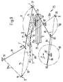
- Figur 3:
- einen den Bereich des Zwischenstapels der Vorrichtung nach Fig. 1 in vergrössertem Massstab und in Seitenansicht darstellenden Ausschnitt aus Fig. 1,
- Figur 4:
- in Seitenansicht den Antriebsmechanismus für die Saugeranordnung der Vorrichtung gemäss den Figuren 1-3,
- Figur 5:
- den Antriebsmechanismus gemäss Fig. 4 im Querschnitt,
- Figur 6:
- in Seitenansicht eine zweite Ausführungsform der erfindungsgemässen Vorrichtung,
- Figur 7:
- die Antriebsvorrichtung für die Saugeranordnung der Vorrichtung gemäss Fig. 6 in Seitenansicht,
- Figur 8:
- den Antriebsmechanismus gemäss
Figur 7 im Querschnitt, - Figur 9:
- den Bewegungsablauf eines Saugkopfes der Saugeranordnung gemäss den Figuren 6-8 anhand einer ganz schematischen Darstellung des Antriebsmechanismus, und
- Figur 10:
- eine dritte Ausführungsform der erfindungsgemässen Vorrichtung in Seitenansicht.
- Figure 1:
- a first embodiment of a device according to the invention in side view,
- Figure 2:
- 1 on an enlarged scale, the device according to FIG. 1 partly in cross section and partly in view,
- Figure 3:
- 1 on an enlarged scale and in side view, a section of the area of the intermediate stack of the device according to FIG. 1,
- Figure 4:
- in side view the drive mechanism for the suction arrangement of the device according to Figures 1-3,
- Figure 5:
- 4 in cross section,
- Figure 6:
- a side view of a second embodiment of the device according to the invention,
- Figure 7:
- 6 shows the drive device for the suction arrangement of the device according to FIG. 6 in a side view,
- Figure 8:
- the drive mechanism according to Figure 7 in cross section,
- Figure 9:
- the movement of a suction head of the suction arrangement according to Figures 6-8 based on a very schematic representation of the drive mechanism, and
- Figure 10:
- a third embodiment of the device according to the invention in side view.
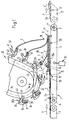
Anhand der Figuren 1-3 wird nun eine erste Ausführungsform einer erfindungsgemässen Vorrichtung beschrieben. Diese Vorrichtung weist eine erste Fördereinrichtung 1 auf, welche gefaltete Druckereierzeugnisse 2 in einer Schuppenformation S zubringt. Dabei liegt in dieser Schuppenformation S jedes Druckereierzeugnis auf dem nachfolgenden Erzeugnis 2 auf. Dies bedeutet, dass in Förderrichtung A der Fördereinrichtung 1 gesehen, die nachlaufende Kante 2a der Druckereierzeugnisse 2 in der Schuppenformation S oben liegt. Beim in den Figuren 1-3 gezeigten Ausführungsbeispiel wird diese nachlaufende Kante der gefalteten Druckereierzeugnisse 2 durch die Falzkante 2a gebildet. Die dieser Falzkante 2a gegenüberliegende offene Seitenkante 2b bildet dementsprechend die Vorlaufkante.A first embodiment of a device according to the invention will now be described with reference to FIGS. 1-3. This device has a first conveyor device 1, which delivers folded printed
Die Fördereinrichtung 1 weist einen Bandförderer 3 sowie einen diesem nachgeschalteten Riemchenförderer 4 auf. Der Riemchenförderer 4 wird durch eine Anzahl von parallel zueinander und einem Abstand voneinander verlaufenden Rundriemchen 5 (Fig. 2) gebildet, die über Umlenkwalzen 6 und 7 geführt sind, von denen die eine Umlenkwalze angetrieben ist. Der Bandförderer 3 und der Riemchenförderer 4 können dieselbe oder unterschiedliche Fördergeschwindigkeit haben. Die Umlenkwalzen 6, 7 sind in zwei parallel zueinander laufenden Armen 8, 9 (Fig. 2) drehbar gelagert. Der Riemchenförderer 4 ist als um die Achse 6' der Umlenkwalze 6 schwenkbare, Wippe ausgebildet und ist auf einer in Fig. 1 nur schematisch dargestellten Kolben-Zylinder-Einheit 10 abgestützt. Mittels letzterer wird auf noch zu beschreibende Weise die Schwenklage des Riemchenförderers 4 eingestellt.The conveyor device 1 has a
Oberhalb und im Endbereich des Riemchenförderers 4 ist ein Anschlag 11 angeordnet, der eine Anzahl von Anschlagfingern 12 (Fig. 2) aufweist, die in einem Abstand voneinander angeordnet sind und sich jeweils zwischen zwei Rundriemchen 5 hindurch erstrecken. In Förderrichtung A gesehen ist vor dem Anschlag 11 eine Förderwalze 13 vorgesehen, welche sich quer zur Förderrichtung A erstreckt und auf der Schuppenformation S aufliegt. Diese Förderwalze 13 ist beiderends je in einem Arm 14 bzw. 15 mittels Lagern 16, 17 (Fig. 2) drehbar gelagert. Die Arme 14, 15 sind ihrerseits am andern Ende auf einer Welle 18 gelagert, und zwar mittels Pendellagern 19, 20. Die Welle 18 durchsetzt die Arme 14, 15 des Riemchenförderers 4 und ist in Lagerteilen 21, 22 gelagert, welche an den Armen 14 bzw. 15 angebracht sind (Fig. 2). Die Lagerung der Welle 18 erfolgt über Lager 23 und 24. Am einen Ende der Welle 18 sitzt auf dieser ein Zahnrad 25, das über eine Antriebskette 26 von einem nicht gezeigten Antrieb angetrieben wird. Dieses Zahnrad 25 kämmt mit einem Zahnrad 27, das fest auf einem Fortsatz 13a der Förderwalze 13 sitzt. Ueber die Kette 26 und die Zahnräder 25, 27 wird somit die Förderwalze 13 in Richtung des Pfeiles T (Fig. 3) umlaufend angetrieben. Die auf die Druckereierzeugnisse 2 eine Förderwirkung ausübende Förderwalze 13 kann sich dank ihrer pendelnden Lagerung an die sich ändernde Höhe der Schuppenformation S anpassen. Da die beiden Lagerarme 14, 15 für die Antriebswalze 13 wie beschrieben unabhängig voneinander pendelnd gelagert sind, kann sich die Förderwalze 13 auch anpassen, wenn in der Schuppenformation S Dickenunterschiede in einer quer zur Förderrichtung A verlaufenden Richtung auftreten.Above and in the end region of the
Zwischen der Förderwalze 13 und dem Anschlag 11 wird eine Stapelstelle 28 festgelegt, an der die Druckereierzeugnisse 2 zu einem Zwischenstapel 29 aufgeschichtet werden. Im Bereich dieses Zwischenstapels 29 ist ein unterhalb der Rundriemchen 5 angeordnetes Stützblech 30 (Fig. 2) angeordnet, durch welches verhindert wird, dass sich die Rundriemchen 5 unter dem Gewicht des Zwischenstapels 29 durchbiegen können.A stacking
Wie aus den Figuren 1-3 hervorgeht, werden die Druckereierzeugnisse 2 durch den Riemchenförderer 4 von unten in den Zwischenstapel 29 eingeschoben. Die angetriebene Förderwalze 13 unterstützt dabei das Einschieben der Druckereierzeugnisse 2 in den Zwischenstapel 29. Durch den Anschlag 11 wird die Vorschubbewegung der Druckererzeugnisse 2 gebremst.As can be seen from FIGS. 1-3, the printed
Mit 31 (Fig. 1) ist rein schematisch eine Höhenüberwachungsanordnung dargestellt, die z. B. als Lichtschranke ausgebildet werden kann. Diese Höhenüberwachungsanordnung 31 ist mit einer nicht dargestellten Steueranordnung verbunden, welche die Zylinder-Kolben-Einheit 10 und damit die Schwenklage des Riemchenförderers 4 steuert. Mittels dieser Höhenüberwachungsanordnung 31 wird dafür gesorgt, dass die Oberseite 29a des Zwischenstapels 29 sich immer etwa auf dem gleichen Niveau H befindet. Dies wird dadurch erreicht, dass bei sich ändernder Höhe des Zwischenstapels 29 der Riemchenförderer 4 mittels der Kolben-Zylinder-Einheit 10 nach oben oder nach unten verschwenkt wird, um die Stapeloberseite 29a auf der gewünschten Höhe H zu halten.With 31 (Fig. 1) a height monitoring arrangement is shown purely schematically, the z. B. can be designed as a light barrier. This
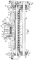
Oberhalb des Riemchenförderers 4 ist eine zweite Fördereinrichtung 32 angeordnet, welche einzeln steuerbare Greifer 33 aufweist, die in regelmässigen Abständen an einer nicht gezeigten, endlos umlaufenden Kette befestigt sind, die in einem Kettenkanal 34 geführt ist. Die Kette und damit auch die Greifer 33 laufen in Richtung des Pfeiles B (Fig. 1) um. Jeder Greifer 33 besitzt ein an der Kette befestigtes Tragelement 35, an dem schwenkbar eine Klemmplatte 36 und zwei mit dieser zusammenwirkende Klemmfinger 37 gelagert sind. Wie Fig. 2 zeigt, stehen die beiden in einem Abstand voneinander angeordneten Klemmfinger 37 unter der Wirkung einer Schliessfeder 38, die den Klemmfinger 37 gegen die Klemmplatte 36 drückt und damit den Greifer 33 geschlossen hält. Die beiden Schliessfedern 38 sind auf einem Bolzen 39 angeordnet, der im Tragelement 35 gelagert ist und um dessen Längsachse die Klemmplatte 36 zusammen mit den zugeordneten Klemmfingern 37 frei schwenkbar ist. Mit jedem Klemmfinger 37 ist ein Steuerarm 40 verbunden, der an seinem Ende eine Steuerrolle 41 trägt. Die Klemmplatten 36 sind mit einem in Förderrichtung B gesehen nach hinten weisenden Ansatz 36a versehen, der dazu bestimmt ist, mit einer Positionierkulisse 42 zusammenzuwirken. Beim Auflaufen des Ansatzes 36a auf die Positionierkulisse 42 werden die Klemmplatte 36 und mit dieser die Klemmfinger 37 in eine bestimmte Position gebracht, in der die Greifer 33 auch geöffnet werden können. Zu diesem Zwecke dient eine Oeffnungskulisse 43, die mit der Steuerrolle 41 zusammenwirkt und ein Abheben der Klemmfinger 37 entgegen der Kraft der Schliessfedern 38 von der Klemmplatte 36 bewirkt.Above the
Um die Druckereierzeugnisse 2 vom Zwischenstapel 29 in den Förderbereich F der Fördereinrichtung 32, d.h. in die Bewegungsbahn der geöffneten Greifer 33 zu bringen, ist eine ganz allgemein mit 44 bezeichnete Saugeranordnung vorgesehen. Diese weist zwei in einem Abstand voneinander angeordnete Saugköpfe 45 und 46 auf (Fig. 2), von denen jeder an einem rohrförmigen Tragarm 47 befestigt ist. An jedem Tragarm ist ein Verbindungsschlauch 48 angeschlossen, der mit einer nicht dargestellten Unterdruckquelle verbunden ist, die periodisch zu- und wegschaltbar ist. Jeder Tragarm 47 ist weiter mit einem in Fig. 2 nur teilweise dargestellten Antrieb 49 verbunden, der anhand der Figuren 4 und 5 noch näher erläutert werden wird. Durch diesen Antrieb 49 werden die Saugköpfe 45, 46 entlang einer geschlossenen, etwa birnenförmigen Umlaufbahn 50 bewegt. Wie die Fig. 2 zeigt, verlaufen diese Umlaufbahnen 50 seitlich der Fördereinrichtung 32. Jede Umlaufbahn 50 verläuft von einer Uebernahmestelle 51, die sich auf der Stapeloberseite 29a im Bereich der nachlaufenden Falzkante 2a der Druckereierzeugnisse 2 befindet, aufwärts zu einer Abgabestelle 52 und dann weiter nach oben und schleifenförmig wieder zurück zur Uebernanmestelle 51. Während der Bewegung der Saugköpfe 45, 46 von der Uebernahmestelle 51 zur Abgabestelle 52 werden die Saugköpfe 45, 46 an die Unterdruckquelle angeschlossen. Dies bedeutet, dass das jeweils oberste Druckereierzeugnis 2' im Zwischenstapel 29 im Bereich des Falzes 2a von den Saugköpfen 45, 46 erfasst und nach oben in den Förderbereich F der Fördereinrichtung 32 mitgenommen wird. Die von den Saugköpfen 45, 46 nach oben abgehobenen Falzkanten 2a der Druckereierzeugnisse 2 werden somit in die Bewegungsbahn jeweils eines offenen Greifers 33 gebracht und gelangen zwischen dessen Klemmplatte 36 und die von dieser abgehobenen Klemmfinger 37. Um dieses Einbringen der Falzkantenbereiche der Druckereierzeugnisse 2 in die offenen Greifer 33 zu ermöglichen, werden die Greifer 33 mittels der Positionierkulisse 42 in die geeignete Schwenklage gebracht. Wie insbesondere aus Fig. 3 ersichtlich ist, werden die Klemmplatte 36 mit den Klemmfingern 37 mittels der Positionierkulisse 42 während der Uebernahme der Druckereiprodukte 2 verschwenkt, damit ein einwandfreies Erfassen der Druckereierzeugisse 2 im Bereich ihres Falzes 2a durch die Greifer 33 sichergestellt wird.In order to bring the printed
Da die beiden Saugköpfe 45 und 46 durch voneinander getrennte Antriebe angetrieben werden, ist es möglich, die beiden Saugköpfe 45, 46 nicht nur synchron miteinander zu bewegen, sondern auch abwechselnd im Gegentakt. Bei einer solchen Lösung würde dann ein Druckereierzeugnis jeweils nur durch einen Saugkopf 45 oder 46 erfasst und transportiert werden. Jeder Saugkopf 45, 46 hat dann nur jedes zweite Druckereierzeugnis 2 zu erfassen.Since the two suction heads 45 and 46 are driven by separate drives, it is possible not only to move the two suction heads 45, 46 synchronously with one another, but also alternately in push-pull. In such a solution, a printed product would then only be detected and transported by a
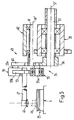
Im folgenden wird nun anhand der Figuren 4 und 5 der Aufbau und die Funktionsweise einer bevorzugten Ausführung des Antriebes 49 für die Saugköpfe 45, 46 beschrieben. Neben dieser dargestellten Ausführungsform ist es selbstverständlich denkbar, diesen Antrieb 49 auch auf andere geeignete Weise auszubilden, um den Saugkopf 45, 46 entlang der birnenförmigen Umlaufbahn 50, die an der Uebernahmestelle 51 eine Spitze bildet, zu bewegen.The structure and the mode of operation of a preferred embodiment of the
Der rohrförmige Tragarm 47, an dem der Saugkopf 45 angebracht ist, ist am einen Arm 53a eines zweiarmigen Hebels 53 befestigt, dessen anderer Arm 53b gegenüber dem Arm 53a abgewinkelt ist. Der Arm 53b bildet die Koppel einer Kurbelschwinge 54 und ist über ein Gelenk 55, dessen Gelenkzapfen mit 55a bezeichnet ist, mit einer Kurbel 56 verbunden. Letztere sitzt auf einer in Richtung des Pfeiles D umlaufend angetriebenen Welle 57, die in einem Lager 58 drehbar gelagert ist. Die Welle 57, deren Längsachse mit 57' bezeichnet ist, wird von einer nicht gezeigten Antriebseinrichtung angetrieben. Am anderen Ende ist der Arm 53b des Hebels 53 über ein Gelenk 59, dessen Gelenkzapfen mit 59a bezeichnet ist, mit einer Schwinge 60 verbunden. Letztere ist auf einer Welle 61 befestigt, die frei drehbar in einem Lager 62 gelagert ist. Die Längsachse dieser Welle 61 ist mit 61' bezeichnet.The
Die Schwinge 60 wird bei sich drehender Kurbel 56 zwischen zwei Endstellungen, die in Fig. 4 gestrichelt dargestellt sind und einen Winkel α einschliessen, hin und her verschwenkt. Die beiden Endlagen der Schwinge 60 sind durch die mit 59a' bzw. 59a'' bezeichneten Positionen des Gelenkzapfens 59a bezeichnet. Die diesen Endlagen 59a' und 59a'' zugeordneten Positionen des Gelenkzapfens 55a sind mit 55a' und 55a'' bezeichnet.With the crank 56 rotating, the
Mittels des beschriebenen Hebelantriebs 49 wird nun der Saugkopf 45 von der Uebernahmestelle 51 entlang des Abschnittes 50a der Umlaufbahn 50 nach oben zur Abgabestelle 52 bewegt. Zwischen Uebernahmestelle 51 und Abgabestelle 52 ist der Saugkopf 45, wie bereits erwähnt, mit der Unterdruckquelle verbunden und nimmt ein Druckereierzeugnis 2 mit. Nach dem Wegschalten der Unterdruckquelle wird das Druckereierzeugnis freigegeben. Der Saugkopf 45 wird weiter in Richtung des Pfeiles C entlang der Umlaufbahn 50 bewegt, bis er wieder zur Uebernahmestelle 51 gelangt, wo das nächste Druckereierzeugnis 2 erfasst wird. Es ist offensichtlich, dass die Umlaufbahn 50 derart gewählt ist, dass der Saugkopf 45 nach Freigabe des Druckereierzeugnisses 2 um dieses herumläuft, so dass das Erfassen der Druckereierzeugnisses durch die Greifer 33 durch die Saugkopfbewegung nicht beeinträchtigt wird.By means of the
Nachfolgend wird nun die Funktionsweise der vorstehend beschriebenen Vorrichtung erläutert, soweit diese sich nicht bereits aus den vorangegangenen Ausführungen ergibt.The mode of operation of the device described above will now be explained below, insofar as this does not already result from the preceding explanations.
Die durch den Bandförderer 3 in Schuppenformation S zugeführten Druckereierzeugnisse 2 werden mit der Falzkante 2a nachlaufend zur Stapelstelle 28 gefördert und an dieser mit Unterstützung der Förderwalze 13 unten in den Zwischenstapel 29 eingeschoben. Das jeweils oberste Druckereierzeugnis 2 im Zwischenstapel 29 wird durch die Saugköpfe 45, 46 im Bereich der Falzkante 2a erfasst und nach oben vom Zwischenstapel 29 abgehoben. Die Falzkante 2a wird in die Bewegungsbahn der offenen Greifer 33 gebracht und zwischen der Klemmplatte 36 und den Klemmfingern 37 festgeklemmt. Das Schliessen der Greifer 33 erfolgt durch die Schliessfedern 38 nach dem Ablaufen der Steuerrolle 41 von der Oeffnungskulisse 43. Die durch die Greifer 33 erfassten Druckereierzeugnisse 2 werden dann noch vollständig vom Zwischenstapel 29 abgehoben und nach oben zu einer nicht dargestellten Weiterverarbeitungsstelle geführt. Die in der zugeführten Schuppenformation S vorlaufende, durch das vorauslaufende Druckereierzeugnis überdeckte offene Seitenkante 2b der Druckereierzeugnisse 2 liegt nach der Uebernahme durch die Fördereinrichtung 32 frei, was bedeutet, dass ein Oeffnen der gefalteten Druckereierzeugnisse möglich ist, während diese durch die Greifer 33 noch gehalten sind.The printed
Dadurch, dass die durch den Bandförderer 3 zugeführten Druckereierzeugnisse 2 nicht direkt den in festen Abständen aufeinanderfolgenden Greifern 33 zugeführt werden, haben allfällige Unregelmässigkeiten im Schuppenabstand, d.h. in den Abständen zwischen aufeinanderfolgenden Druckereierzeugnissen 2 in der Schuppenformation S, sowie fehlende Druckereierzeugnisse 2 in der Schuppenformation S keinen Einfluss auf eine einwandfreie Uebernahme durch die Greifer 33. Solche Unregelmässigkeiten werden durch den Zwischenstapel 29 ausgeglichen. Das phasenrichtige Zuführen der Druckereierzeugnisse 2 zu den Greifern 33 erfolgt mittels der Saugeranordnung 44 und ist somit innerhalb gewisser Grenzen unabhängig von der Zufuhr der Druckereierzeugnisse 2 durch den Bandförderer 3.Because the printed
Andererseits ist es selbst bei konstanter Zulieferung von Druckereierzeugnissen 2 durch den Bandförderer 3 problemlos möglich, bei Bedarf auf die Beschickung gewisser Greifer 33 durch ein Druckereierzeugnis 2 zu verzichten. Hierzu genügt es, im geeigneten Zeitpunkt auf das Herstellen einer Verbindung zwischen dem Saugkopf 45, 46 und der Unterdruckquelle zu verzichten, so dass der Saugkopf 45, 46 eine Bewegung entlang der Umlaufbahn 50 macht, ohne dabei ein Erzeugnis 2 mitzunehmen.On the other hand, even with a constant supply of printed
Um auch dickere Druckereierzeugnisse sicher erfassen zu können, ist die Saugeranordnung 44 so ausgebildet, dass die Saugköpfe 45, 46 wie beschrieben im Bereich des Falzes 2a an den Druckereierzeugnissen 2 angreifen.In order to be able to reliably grasp even thicker printed products, the
Fällt nun die Schuppenformation S anders als wie in Fig. 1 gezeigt an, d.h. mit dem Falz 2a der Druckereierzeugnisse als vorlaufende, unten liegende Kante, so müsste die Schuppenformation S von der anderen Seite her der Stapelstelle 28 zugeführt werden. Diese Variante ist in Fig. 1 auf der rechten Seite strichpunktiert dargestellt. Der Bandförderer 3' fördert die Schuppenformation S', in der jedes Druckereierzeugnis 2 nach wie vor auf dem nachlaufenden Druckereierzeugnis aufliegt, die vorlaufende Kante jedoch die Falzkante 2a ist, in Richtung des Pfeiles A', die der Förderrichtung A des Bandförderers 3 entgegengesetzt ist. Bei dieser Variante bleibt die Saugeranordnung 44 und die Fördereinrichtung 32 gleich, doch muss der Riemchenförderer 4 statt um die Achse 6' um die Achse 7' der Umlenkwalze 7 schwenkbar gelagert sein. Zudem sind Anschlag 11 und Förderwalze 13 gegeneinander auszutauschen, wie das ja aus Fig. 1 offensichtlich ist. Das Erfassen und Zubringen der Druckereierzeugnisse 2 in den Förderbereich F der Greifer 33 erfolgt bei dieser Variante gleich wie anhand der Fig. 1 bereits beschrieben.If the scale formation S is produced differently than as shown in FIG. 1, ie with the
Die in Fig. 6 gezeigte Ausführungsform ist der Ausführungsform gemäss den Figuren 1-3 sehr ähnlich und unterscheidet sich von letzterer nur durch eine andere Ausgestaltung der Saugeranordnung und des Zubringens der Druckereierzeugnisse 2 ab dem Zwischenstapel 29 zu den Greifern 33. In dieser Figur 6 sind für sich entsprechende Teile dieselben Bezugszeichen benützt wie in den Figuren 1-3.The embodiment shown in FIG. 6 is very similar to the embodiment according to FIGS. 1-3 and differs from the latter only in a different configuration of the suction arrangement and the delivery of the printed
Die Vorrichtung gemäss Fig. 6 dient dazu, Druckereierzeugnisse 2 zu verarbeiten, die innerhalb der zugeführten Schuppenformation S eine andere Lage einnehmen als in der Schuppenformation S, die der Vorrichtung gemäss den Figuren 1-3 zugeführt wird. Wie aus Fig. 6 ersichtlich ist, liegt in der vom Bandförderer 3 zugeführten Schuppenformation S auch jedes Druckereierzeugnis 2 auf dem nachfolgenden Druckereierzeugnis auf. Doch werden die vorlaufenden und damit verdeckten Kanten der Druckereierzeugnisse 2 im Gegensatz zur in Fig. 1 gezeigten Schuppenformation S durch die Falzkanten 2a gebildet. Dies bedeutet, dass die Druckereierzeugnisse 2 durch die in Fig. 6 mit 65 bezeichnete Saugeranordnung im Bereich ihrer am Anschlag 11 anstehenden Kante 2a erfasst werden müssen. Im Gegensatz zur Ausführungsform gemäss den Figuren 1-3 werden nun aber die Druckereierzeugnisse 2 nicht mit ihrer Falzkante 2a in die Greifer 33 eingebracht, sondern mit ihrer gegenüberliegenden offenen Seitenkante 2b.The device according to FIG. 6 is used to process printed
Die Saugeranordnung 65 weist gleich wie die Ausführungsform gemäss den Figuren 1-3 zwei synchron oder allenfalls in Gegentakt arbeitende Saugköpfe 66 auf, von denen in Fig. 6 nur ein Saugkopf gezeigt ist. Dieser wird mittels eines noch näher zu beschreibenden Antriebes zwischen einer Uebernahmestelle 67, an der er ein Druckererzeugnis 2 ergreift, und einer Abgabestelle 68, an der das erfasste Erzeugnis 2 freigegeben wird, entlang der mit 70 bezeichneten Bewegungsbahn hin und her bewegt. Während der Bewegung von der Uebernahmestelle 67 zur Abgabestelle 68 ist der Saugkopf 66 wie bereits früher beschrieben mit einer Unterdruckquelle verbunden und hebt das oberste Druckereierzeugnis 2 vom Zwischenstapel 29 ab und schiebt es entgegen der Zuförderrichtung A in Richtung des Pfeiles E gegen die Fördereinrichtung 32 zurück. Um die Kanten 2b der Druckereierzeugnisse in den Förderbereich der Fördereinrichtung 32, d.h. in die Bewegungsbahn der offenen Greifer 33 zu bringen, ist an der dem Anschlag 11 gegenüberliegenden Kante des Zwischenstapels 29 ein Leitorgan 71 vorgesehen, das die beim Zurückbewegen der Druckereierzeugnisse 2 vorlaufende Kante 2b nach oben in den erwähnten Förderbereich F umlenkt.Like the embodiment according to FIGS. 1-3, the
Anhand der Figuren 7-9 wird nun der Aufbau und die Wirkungsweise der Antriebsvorrichtung für den Saugkopf 66 erläutert.The structure and the mode of operation of the drive device for the
Der Saugkopf 66 ist an einem rohrförmigen Tragarm 72 befestigt, der über eine Schlauchleitung mit einer nicht dargestellten Unterdruckquelle verbunden ist. Dieser Tragarm 72 ist mit einem Antrieb 73 verbunden, der einen Hebel 75 aufweist, mit dem der Tragarm 72 fest verbunden ist. Dieser Hebel 75 steht an beiden Enden über Gelenke 76 und 77 mit weiteren Hebeln in Verbindung. Mittels des Gelenkes 76, dessen Achse mit 76' bezeichnet ist, ist der Hebel 75 mit einem Hebel 78 verbunden, der drehfest auf einer Welle 79 mit der Achse 79' sitzt, die schwenkbar in einem Lager 80 gelagert ist. Ueber das andere Gelenk 77 mit der Achse 77' steht der Hebel 75 mit einem weiteren Hebel 81 in Verbindung, der schwenkbar in einem Lager 82 gelagert ist. Der zweiarmige Hebel 81 ist am anderen Ende über ein weiteres Gelenk 83 mit der Koppel 84 eines Kurbelantriebes verbunden, welche über ein Gelenk 85 mit einer Kurbel 86 verbunden ist. Letztere sitzt auf einer Welle 87 mit der Achse 87', die in einem Lager 88 gelagert ist und mit einem nicht gezeigten Antrieb verbunden ist. Die Kurbel 86 läuft in Richtung des Pfeiles K um.The
Anhand der Fig. 9, welche das vorstehend beschriebene Hebelgetriebe nur schematisch zeigt, wird nun die Funktionsweise des Antriebes 73 erläutert.The mode of operation of the
Das Verbindungsgelenk 85 zwischen der Kurbel 86 und der Koppel 84 läuft wie bereits erwähnt entlang einer kreisförmigen Bahn 89 um. Der Hebel 81 führt dabei eine Schwenkbewegung um die Achse 82' seines Lagers 82 aus. Die beiden Endlagen des Hebels 81 sind einerseits mit einer ausgezogenen Linie und andererseits mit einer strichpunktierten Linie dargestellt. Die beiden Gelenke 77 und 83 des Hebels 81 bewegen sich dabei entlang der Bahnen 90 und 91 zwischen den Punkten I und II hin und her. Der Hebel 78 schwingt von der mit einer ausgezogenen Linie dargestellten Stellung in die strichpunktiert dargestellte Stellung 78a und wieder zurück, wobei sich das Gelenk 76 entlang der Bahn 92 zwischen den Punkten I' und II' hin und her bewegt. Durch diese Schwingbewegung der Hebel 81 und 78 ergibt sich auch die Bewegung des Hebels 75, an dem fest der Tragarm 72 des Saugkopfes 66 angebracht ist. Der Saugkopf 66 wird somit von der Uebernahmestelle 67 entlang der etwas gekrümmten Bewegungsbahn zur Abgabestelle 68 und auf derselben Bahn wieder zurück zur Uebernahmestelle 67 bewegt.As already mentioned, the connecting joint 85 between the
Auf der rechten Seite der Figur 6 ist mit strichpunktierten Linien vergleichbar zur Fig. 1 eine Variante angedeutet, bei der der Bandförderer 3' die Schuppenformation S' in einer Richtung A' zur Stapelstelle 28 fördert, die der Förderrichtung A des Bandförderers 3 entgegengesetzt ist. Diese Variante kommt dann zur Anwendung, wenn in der zugeführten Schuppenformation S' die Falzkante 2a die nachlaufende, oben liegende Kante ist. Gleich wie anhand der Fig. 1 beschrieben, müssen bei dieser Variante der Anschlag 11 und die Förderwalze 13,das Leitorgan 71 sowie die Höhenüberwachungsanordnung31 gegeneinander ausgetauscht werden. Zudem muss der Riemchenförderer 4 um die Achse 7a der Umlenkwalze 7 schwenkbar gelagert sein. Demgegenüber muss an der Saugeranordnung 65 nichts geändert werden.On the right-hand side of FIG. 6, a variant is indicated with dash-dotted lines, comparable to FIG. 1, in which the belt conveyor 3 'conveys the scale formation S' in a direction A 'to the stacking
In Fig. 10 ist noch eine dritte Ausführungsform der erfindungsgemässen Vorrichtung gezeigt, die der Ausführungsform gemäss Fig. 6 sehr ähnlich ist und sich von dieser nur durch eine andere Ausbildung der zweiten Fördereinrichtung unterscheidet.FIG. 10 shows a third embodiment of the device according to the invention, which is very similar to the embodiment according to FIG. 6 and differs from it only in a different design of the second conveying device.
Anstelle einer Fördereinrichtung 32 mit einzeln steuerbaren Greifern 33 gemäss Fig. 6 wird bei der Vorrichtung gemäss Fig. 10 die Fördereinrichtung 93 durch zwei übereinander angeordnete Bandförderer 94 und 95 gebildet, welche zwischen sich eine Förderspalt 96 bilden. Die Förderrichtung der Fördereinrichtung 93 ist mit L bezeichnet.Instead of a
Das jeweils oberste Druckereierzeugnis 2 im Zwischenstapel 29 wird durch die Saugeranordnung 65, wie im Zusammenhang mit den Figuren 6-9 beschrieben, etwas vom Stapel 29 abgehoben und in Richtung des Pfeiles E zurückgeschoben. Die dabei vorlaufende, offene Kante 2b der Druckereierzeugnisse 2 wird durch das Leitorgan 71 in den Einlauf 96a des Förderspaltes 96 umgelenkt.The uppermost printed
Wie die Figur 10 zeigt, werden die Druckereierzeugnisse 2 durch die Fördereinrichtung 93 wieder in einer Schuppenformation S₁ weggefördert, in der jedes Druckereierzeugnis 2 auf dem nachfolgenden Druckereierzeugnis aufliegt. Doch wird in dieser Schuppenformation S₁ die vorlaufende Kante 2b durch diejenige Kante gebildet, welche im zugeführten Schuppenstrom S die nachlaufende Kante bildete.As FIG. 10 shows, the printed
Auf der rechten Seite der Figur 10 ist strichpunktiert dieselbe Variante gezeigt wie in Fig. 6.The same variant as in FIG. 6 is shown in dash-dot lines on the right side of FIG. 10.
Bei allen gezeigten Ausführungsformen kann der Riemchenförderer 4 etwa horizontal verlaufen (wie in Fig.1 gezeigt) oder wie in den Fig.6 und 10 dargestellt in Förderrichtung abfallend schräggestellt sein.In all of the embodiments shown, the apron conveyor can 4 run approximately horizontally (as shown in FIG. 1) or, as shown in FIGS. 6 and 10, are inclined sloping in the conveying direction.
Claims (18)
Applications Claiming Priority (3)
| Application Number | Priority Date | Filing Date | Title |
|---|---|---|---|
| CH4692 | 1992-01-09 | ||
| CH46/92 | 1992-01-09 | ||
| SG141794A SG141794G (en) | 1992-01-09 | 1994-10-01 | Process and apparatus for delivering preferably folded printing products to a further processing point |
Publications (2)
| Publication Number | Publication Date |
|---|---|
| EP0551601A1 true EP0551601A1 (en) | 1993-07-21 |
| EP0551601B1 EP0551601B1 (en) | 1996-06-05 |
Family
ID=25683350
Family Applications (1)
| Application Number | Title | Priority Date | Filing Date |
|---|---|---|---|
| EP92120375A Expired - Lifetime EP0551601B1 (en) | 1992-01-09 | 1992-11-28 | Method and device for feeding particularly folded printed products to a further processing station |
Country Status (17)
| Country | Link |
|---|---|
| US (1) | US5398920A (en) |
| EP (1) | EP0551601B1 (en) |
| JP (1) | JP2928038B2 (en) |
| KR (1) | KR970000773B1 (en) |
| AT (1) | ATE138886T1 (en) |
| AU (1) | AU645716B2 (en) |
| BR (1) | BR9205180A (en) |
| CA (1) | CA2086633C (en) |
| DE (1) | DE59206494D1 (en) |
| DK (1) | DK0551601T3 (en) |
| ES (1) | ES2088075T3 (en) |
| FI (1) | FI106250B (en) |
| GB (1) | GB2260123B (en) |
| HK (1) | HK133994A (en) |
| NO (1) | NO302286B1 (en) |
| RU (1) | RU2067540C1 (en) |
| SG (1) | SG141794G (en) |
Cited By (10)
| Publication number | Priority date | Publication date | Assignee | Title |
|---|---|---|---|---|
| DE4241885C1 (en) * | 1992-10-05 | 1993-11-25 | Ferag Ag | Control arrangement for a device for feeding printed products to a further processing point |
| EP0709218A1 (en) | 1994-10-27 | 1996-05-01 | Ferag AG | Process and device for marking printed products |
| EP0755886A1 (en) * | 1995-07-25 | 1997-01-29 | Ferag AG | Device for feeding printed products to a further work station |
| US5636832A (en) * | 1994-03-24 | 1997-06-10 | Ferag Ag | Apparatus for feeding sheet-like products to a discharge location |
| EP0806391A1 (en) * | 1996-05-06 | 1997-11-12 | Ferag AG | Device for feeding printed articles to a further work station |
| DE19515506B4 (en) * | 1994-05-31 | 2004-11-18 | Ferag Ag | Device for processing printed products |
| DE19627490B4 (en) * | 1995-07-27 | 2005-02-24 | Ferag Ag | Conveyor for printed matter |
| DE19603040B4 (en) * | 1995-03-31 | 2006-05-24 | Ferag Ag | suction element |
| EP1834913A1 (en) * | 2006-03-17 | 2007-09-19 | Ferag AG | Device for picking up and conveying of flat products |
| EP2017209A1 (en) * | 2007-07-17 | 2009-01-21 | Müller Martini Holding AG | Method and device for transferring printing products in shingled formation to an endless conveyor carrying grippers |
Families Citing this family (13)
| Publication number | Priority date | Publication date | Assignee | Title |
|---|---|---|---|---|
| EP0628505B1 (en) * | 1993-05-21 | 1997-07-23 | Ferag AG | Device for separating piled, printed products |
| DE59406254D1 (en) * | 1993-06-29 | 1998-07-23 | Ferag Ag | Device for delivering products such as cards and samples to a processing station |
| GB9508478D0 (en) * | 1995-04-26 | 1995-06-14 | Rensen Alan M S | Feeder for sheet form elements |
| DE19627830B4 (en) * | 1995-07-31 | 2005-07-28 | Ferag Ag | Device for feeding printed products to a removal conveyor |
| US5819663A (en) * | 1995-09-06 | 1998-10-13 | Quad/Tech, Inc. | Gripper conveyor with preliminary ink jet |
| EP0863099B1 (en) * | 1997-03-04 | 2001-11-21 | Ferag AG | Device for separating piled printed products |
| CH692617A5 (en) * | 1998-02-27 | 2002-08-30 | Ferag Ag | Apparatus for processing flexible, sheet-like products. |
| US6748294B1 (en) * | 2000-10-23 | 2004-06-08 | Bowe Bell + Howell Postal Systems Company | Flats bundle collator |
| EP1364900B1 (en) * | 2002-05-22 | 2006-08-30 | Ferag AG | Method for transporting flat and flexible products, and device for carrying out the method |
| US6755412B1 (en) | 2002-07-23 | 2004-06-29 | Charles Dwayne Glowner | High speed overlapping insert feeding assembly |
| EP1943173B1 (en) * | 2005-11-01 | 2011-09-21 | Ferag AG | Method of, and apparatus for, transferring sheet-like products from a stack of products to a conveying belt |
| EP2004532B1 (en) * | 2006-04-12 | 2016-03-30 | Ferag AG | Gripper for holding and conveying flat objects |
| DE102010043063B4 (en) * | 2010-10-28 | 2012-11-08 | Böwe Systec Gmbh | Apparatus and method for buffering a plurality of goods or crop groups and paper handling equipment therewith |
Citations (2)
| Publication number | Priority date | Publication date | Assignee | Title |
|---|---|---|---|---|
| EP0330868A1 (en) * | 1988-03-03 | 1989-09-06 | Ferag AG | Process and device for conveying away printed products fed in a shingled formation |
| EP0368009A1 (en) * | 1988-11-11 | 1990-05-16 | Ferag AG | Method and device for advancing printed articles |
Family Cites Families (11)
| Publication number | Priority date | Publication date | Assignee | Title |
|---|---|---|---|---|
| GB489963A (en) * | 1936-03-05 | 1938-08-08 | John Dickinson & Company Ltd | Improvements in or relating to envelope making machines |
| US3255652A (en) * | 1963-09-16 | 1966-06-14 | Miehle Goss Dexter Inc | Apparatus for handling sheets |
| JPS5216434B2 (en) * | 1971-09-20 | 1977-05-09 | ||
| NL7312656A (en) * | 1973-09-13 | 1975-03-17 | Packotom B V | DEVICE FOR STACKING SINGLE SHEETS. |
| CH630583A5 (en) * | 1978-06-30 | 1982-06-30 | Ferag Ag | DEVICE FOR MOVING AWAY OF FLAT PRODUCTS INCLUDING IN A DOMESTIC FLOW, IN PARTICULAR PRINTED PRODUCTS. |
| US4369959A (en) * | 1979-11-10 | 1983-01-25 | Hornbuckle William M | Sheet feed machine |
| JPS5914452Y2 (en) * | 1981-10-20 | 1984-04-27 | 株式会社篠原鉄工所 | Sheet-fed printing press paper feeding device |
| US4478400A (en) * | 1982-05-19 | 1984-10-23 | Suburban Duplicator Repair, Inc. | Envelope feeder for a duplicating press |
| US4762314A (en) * | 1987-06-17 | 1988-08-09 | Hiroshi Harada | Envelope feeder |
| GB2205819A (en) * | 1987-06-17 | 1988-12-21 | Hiroshi Harada | Envelope feeder |
| US4805890A (en) * | 1987-08-06 | 1989-02-21 | Merrill David Martin | Sheet stacking machine |
-
1992
- 1992-11-26 AU AU29683/92A patent/AU645716B2/en not_active Ceased
- 1992-11-26 GB GB9224763A patent/GB2260123B/en not_active Expired - Fee Related
- 1992-11-28 DE DE59206494T patent/DE59206494D1/en not_active Expired - Lifetime
- 1992-11-28 DK DK92120375.8T patent/DK0551601T3/en active
- 1992-11-28 ES ES92120375T patent/ES2088075T3/en not_active Expired - Lifetime
- 1992-11-28 AT AT92120375T patent/ATE138886T1/en active
- 1992-11-28 EP EP92120375A patent/EP0551601B1/en not_active Expired - Lifetime
- 1992-12-21 KR KR1019920024934A patent/KR970000773B1/en not_active IP Right Cessation
- 1992-12-29 BR BR9205180A patent/BR9205180A/en not_active IP Right Cessation
- 1992-12-29 US US07/997,886 patent/US5398920A/en not_active Expired - Lifetime
-
1993
- 1993-01-04 CA CA002086633A patent/CA2086633C/en not_active Expired - Fee Related
- 1993-01-06 RU RU9393004437A patent/RU2067540C1/en not_active IP Right Cessation
- 1993-01-07 FI FI930045A patent/FI106250B/en not_active IP Right Cessation
- 1993-01-08 JP JP5001704A patent/JP2928038B2/en not_active Expired - Fee Related
- 1993-01-08 NO NO930057A patent/NO302286B1/en not_active IP Right Cessation
-
1994
- 1994-10-01 SG SG141794A patent/SG141794G/en unknown
- 1994-12-01 HK HK133994A patent/HK133994A/en not_active IP Right Cessation
Patent Citations (2)
| Publication number | Priority date | Publication date | Assignee | Title |
|---|---|---|---|---|
| EP0330868A1 (en) * | 1988-03-03 | 1989-09-06 | Ferag AG | Process and device for conveying away printed products fed in a shingled formation |
| EP0368009A1 (en) * | 1988-11-11 | 1990-05-16 | Ferag AG | Method and device for advancing printed articles |
Cited By (14)
| Publication number | Priority date | Publication date | Assignee | Title |
|---|---|---|---|---|
| US5419678A (en) * | 1992-10-05 | 1995-05-30 | Ferag Ag | Control arrangement for an apparatus for delivering printing products |
| DE4241885C1 (en) * | 1992-10-05 | 1993-11-25 | Ferag Ag | Control arrangement for a device for feeding printed products to a further processing point |
| US5636832A (en) * | 1994-03-24 | 1997-06-10 | Ferag Ag | Apparatus for feeding sheet-like products to a discharge location |
| DE19515506B4 (en) * | 1994-05-31 | 2004-11-18 | Ferag Ag | Device for processing printed products |
| EP0709218A1 (en) | 1994-10-27 | 1996-05-01 | Ferag AG | Process and device for marking printed products |
| DE19603040C5 (en) * | 1995-03-31 | 2012-09-13 | Ferag Ag | suction element |
| DE19603040B4 (en) * | 1995-03-31 | 2006-05-24 | Ferag Ag | suction element |
| EP0755886A1 (en) * | 1995-07-25 | 1997-01-29 | Ferag AG | Device for feeding printed products to a further work station |
| AU698518B2 (en) * | 1995-07-25 | 1998-10-29 | Ferag Ag | Apparatus for delivering printed products to a further- processing location |
| DE19627490B4 (en) * | 1995-07-27 | 2005-02-24 | Ferag Ag | Conveyor for printed matter |
| EP0806391A1 (en) * | 1996-05-06 | 1997-11-12 | Ferag AG | Device for feeding printed articles to a further work station |
| EP1834913A1 (en) * | 2006-03-17 | 2007-09-19 | Ferag AG | Device for picking up and conveying of flat products |
| EP2017209A1 (en) * | 2007-07-17 | 2009-01-21 | Müller Martini Holding AG | Method and device for transferring printing products in shingled formation to an endless conveyor carrying grippers |
| US7784784B2 (en) | 2007-07-17 | 2010-08-31 | Mueller Martini Holding Ag | Method and apparatus for transferring printed products conveyed in an shingled flow to a transporter with circulating clamps |
Also Published As
| Publication number | Publication date |
|---|---|
| AU645716B2 (en) | 1994-01-20 |
| US5398920A (en) | 1995-03-21 |
| AU2968392A (en) | 1993-07-15 |
| BR9205180A (en) | 1993-07-13 |
| NO930057D0 (en) | 1993-01-08 |
| ATE138886T1 (en) | 1996-06-15 |
| GB9224763D0 (en) | 1993-01-13 |
| NO302286B1 (en) | 1998-02-16 |
| RU2067540C1 (en) | 1996-10-10 |
| GB2260123A (en) | 1993-04-07 |
| JP2928038B2 (en) | 1999-07-28 |
| SG141794G (en) | 1995-01-13 |
| CA2086633A1 (en) | 1993-07-10 |
| CA2086633C (en) | 1999-08-17 |
| KR970000773B1 (en) | 1997-01-20 |
| FI930045A (en) | 1993-07-10 |
| DE59206494D1 (en) | 1996-07-11 |
| FI106250B (en) | 2000-12-29 |
| HK133994A (en) | 1994-12-09 |
| NO930057L (en) | 1993-07-12 |
| ES2088075T3 (en) | 1996-08-01 |
| GB2260123B (en) | 1994-05-25 |
| DK0551601T3 (en) | 1996-07-01 |
| FI930045A0 (en) | 1993-01-07 |
| JPH0624617A (en) | 1994-02-01 |
| EP0551601B1 (en) | 1996-06-05 |
| KR930016241A (en) | 1993-08-26 |
Similar Documents
| Publication | Publication Date | Title |
|---|---|---|
| EP0551601B1 (en) | Method and device for feeding particularly folded printed products to a further processing station | |
| EP0218872B1 (en) | Device for gathering various printed products | |
| DE3512737C2 (en) | Feeder of booklets, sheets and similar products for feeding devices in packaging machines, bookbinding machines and the like. | |
| DE3608055C2 (en) | Device for loading a separating device for printed products, in particular an investor | |
| EP0330868B1 (en) | Process and device for conveying away printed products fed in a shingled formation | |
| CH630583A5 (en) | DEVICE FOR MOVING AWAY OF FLAT PRODUCTS INCLUDING IN A DOMESTIC FLOW, IN PARTICULAR PRINTED PRODUCTS. | |
| DE1761688B2 (en) | Transport device for flat structures occurring in a scale formation | |
| EP0368009B1 (en) | Method and device for advancing printed articles | |
| EP0305671B1 (en) | Conveyor for prints, and use of the conveyor | |
| EP0564812B1 (en) | Method and device for opening folded printing products | |
| EP0522319B1 (en) | Method and device for opening flexible articles folded off-centre | |
| DE3306815C2 (en) | DEVICE FOR TRANSPORTING FLAT PRODUCTS INCLUDED IN A DANDEL INFORMATION, IN PARTICULAR PRINTED PRODUCTS | |
| EP0553455B1 (en) | Method and device for lifting printed products from a stack | |
| EP0242702B1 (en) | Method and device for turning continually arriving flat products | |
| EP0600216B1 (en) | Method and device for opening folded printing products | |
| DE2058606A1 (en) | Method and device for the lateral alignment of sheets, in particular in a printing press | |
| EP0300171B1 (en) | Device for transporting flat products, in particular printed products | |
| EP0218804B1 (en) | Device for taking over and transferring folded sheets from a conveyor | |
| EP0518064B1 (en) | Method and apparatus for handling of printed products | |
| WO2000024660A1 (en) | Method and device for delivering printed products | |
| EP1072546B1 (en) | Conveyer for collating and processing printed sheets | |
| EP0863099B1 (en) | Device for separating piled printed products | |
| DE2440106A1 (en) | DEVICE FOR APPLYING ADHESIVE | |
| DE19509487C1 (en) | Sheet feed mechanism to printing press | |
| EP1310443A2 (en) | Sheet feeder |
Legal Events
| Date | Code | Title | Description |
|---|---|---|---|
| PUAI | Public reference made under article 153(3) epc to a published international application that has entered the european phase |
Free format text: ORIGINAL CODE: 0009012 |
|
| AK | Designated contracting states |
Kind code of ref document: A1 Designated state(s): AT BE CH DE DK ES FR IT LI NL SE |
|
| 17P | Request for examination filed |
Effective date: 19930830 |
|
| 17Q | First examination report despatched |
Effective date: 19941213 |
|
| GRAH | Despatch of communication of intention to grant a patent |
Free format text: ORIGINAL CODE: EPIDOS IGRA |
|
| GRAH | Despatch of communication of intention to grant a patent |
Free format text: ORIGINAL CODE: EPIDOS IGRA |
|
| GRAA | (expected) grant |
Free format text: ORIGINAL CODE: 0009210 |
|
| AK | Designated contracting states |
Kind code of ref document: B1 Designated state(s): AT BE CH DE DK ES FR IT LI NL SE |
|
| REF | Corresponds to: |
Ref document number: 138886 Country of ref document: AT Date of ref document: 19960615 Kind code of ref document: T |
|
| REG | Reference to a national code |
Ref country code: CH Ref legal event code: NV Representative=s name: SCHAAD, BALASS & PARTNER AG |
|
| REG | Reference to a national code |
Ref country code: ES Ref legal event code: BA2A Ref document number: 2088075 Country of ref document: ES Kind code of ref document: T3 |
|
| REG | Reference to a national code |
Ref country code: DK Ref legal event code: T3 |
|
| REF | Corresponds to: |
Ref document number: 59206494 Country of ref document: DE Date of ref document: 19960711 |
|
| ITF | It: translation for a ep patent filed |
Owner name: SOCIETA' ITALIANA BREVETTI S.P.A. |
|
| REG | Reference to a national code |
Ref country code: ES Ref legal event code: FG2A Ref document number: 2088075 Country of ref document: ES Kind code of ref document: T3 |
|
| ET | Fr: translation filed | ||
| PLBE | No opposition filed within time limit |
Free format text: ORIGINAL CODE: 0009261 |
|
| STAA | Information on the status of an ep patent application or granted ep patent |
Free format text: STATUS: NO OPPOSITION FILED WITHIN TIME LIMIT |
|
| 26N | No opposition filed | ||
| REG | Reference to a national code |
Ref country code: CH Ref legal event code: PFA Owner name: FERAG AG Free format text: FERAG AG##CH-8340 HINWIL (CH) -TRANSFER TO- FERAG AG#PATENTABTEILUNG Z. H. MARKUS FELIX ZUERICHSTRASSE 74#8340 HINWIL (CH) |
|
| PGFP | Annual fee paid to national office [announced via postgrant information from national office to epo] |
Ref country code: ES Payment date: 20091123 Year of fee payment: 18 |
|
| PGFP | Annual fee paid to national office [announced via postgrant information from national office to epo] |
Ref country code: FR Payment date: 20101130 Year of fee payment: 19 Ref country code: AT Payment date: 20101112 Year of fee payment: 19 Ref country code: NL Payment date: 20101111 Year of fee payment: 19 |
|
| PGFP | Annual fee paid to national office [announced via postgrant information from national office to epo] |
Ref country code: DE Payment date: 20101119 Year of fee payment: 19 |
|
| PGFP | Annual fee paid to national office [announced via postgrant information from national office to epo] |
Ref country code: BE Payment date: 20101117 Year of fee payment: 19 Ref country code: IT Payment date: 20101126 Year of fee payment: 19 |
|
| REG | Reference to a national code |
Ref country code: ES Ref legal event code: FD2A Effective date: 20120110 |
|
| PG25 | Lapsed in a contracting state [announced via postgrant information from national office to epo] |
Ref country code: ES Free format text: LAPSE BECAUSE OF NON-PAYMENT OF DUE FEES Effective date: 20101129 |
|
| PGFP | Annual fee paid to national office [announced via postgrant information from national office to epo] |
Ref country code: SE Payment date: 20111128 Year of fee payment: 20 Ref country code: CH Payment date: 20111116 Year of fee payment: 20 Ref country code: DK Payment date: 20111118 Year of fee payment: 20 |
|
| BERE | Be: lapsed |
Owner name: *FERAG A.G. Effective date: 20111130 |
|
| REG | Reference to a national code |
Ref country code: NL Ref legal event code: V1 Effective date: 20120601 |
|
| PG25 | Lapsed in a contracting state [announced via postgrant information from national office to epo] |
Ref country code: NL Free format text: LAPSE BECAUSE OF NON-PAYMENT OF DUE FEES Effective date: 20120601 |
|
| REG | Reference to a national code |
Ref country code: FR Ref legal event code: ST Effective date: 20120731 |
|
| PG25 | Lapsed in a contracting state [announced via postgrant information from national office to epo] |
Ref country code: IT Free format text: LAPSE BECAUSE OF NON-PAYMENT OF DUE FEES Effective date: 20111128 Ref country code: BE Free format text: LAPSE BECAUSE OF NON-PAYMENT OF DUE FEES Effective date: 20111130 |
|
| REG | Reference to a national code |
Ref country code: DE Ref legal event code: R071 Ref document number: 59206494 Country of ref document: DE |
|
| REG | Reference to a national code |
Ref country code: DE Ref legal event code: R071 Ref document number: 59206494 Country of ref document: DE |
|
| REG | Reference to a national code |
Ref country code: CH Ref legal event code: PL |
|
| REG | Reference to a national code |
Ref country code: AT Ref legal event code: MM01 Ref document number: 138886 Country of ref document: AT Kind code of ref document: T Effective date: 20111128 |
|
| PG25 | Lapsed in a contracting state [announced via postgrant information from national office to epo] |
Ref country code: FR Free format text: LAPSE BECAUSE OF NON-PAYMENT OF DUE FEES Effective date: 20111130 |
|
| REG | Reference to a national code |
Ref country code: SE Ref legal event code: EUG |
|
| PG25 | Lapsed in a contracting state [announced via postgrant information from national office to epo] |
Ref country code: AT Free format text: LAPSE BECAUSE OF NON-PAYMENT OF DUE FEES Effective date: 20111128 |