EP0551971A1 - Use of a fastening system - Google Patents
Use of a fastening system Download PDFInfo
- Publication number
- EP0551971A1 EP0551971A1 EP93250003A EP93250003A EP0551971A1 EP 0551971 A1 EP0551971 A1 EP 0551971A1 EP 93250003 A EP93250003 A EP 93250003A EP 93250003 A EP93250003 A EP 93250003A EP 0551971 A1 EP0551971 A1 EP 0551971A1
- Authority
- EP
- European Patent Office
- Prior art keywords
- adhesive
- metal
- adhesive system
- strips
- attached
- Prior art date
- Legal status (The legal status is an assumption and is not a legal conclusion. Google has not performed a legal analysis and makes no representation as to the accuracy of the status listed.)
- Withdrawn
Links
Images


Classifications
-
- H—ELECTRICITY
- H02—GENERATION; CONVERSION OR DISTRIBUTION OF ELECTRIC POWER
- H02B—BOARDS, SUBSTATIONS OR SWITCHING ARRANGEMENTS FOR THE SUPPLY OR DISTRIBUTION OF ELECTRIC POWER
- H02B1/00—Frameworks, boards, panels, desks, casings; Details of substations or switching arrangements
- H02B1/26—Casings; Parts thereof or accessories therefor
- H02B1/30—Cabinet-type casings; Parts thereof or accessories therefor
Definitions
- Textile fasteners based on Velcro fastener elements are known for connecting parts of clothing or footwear. It is also known to use Velcro fasteners of this type also for fastening rigid bodies to solid supports or wall surfaces (DE-A-40 12 613, DE-A-40 07 586).
- the invention has for its object to more efficiently attach parts of electrical cabinets or switchgear cabinets consisting of such cabinets than has previously been done by screws, locking bolts or similar elements.
- this object is achieved by using an adhesive system consisting of two strips which can be placed one on top of the other and which are to be fixedly attached to the components to be connected and which have a large number of flexible elements which can be releasably brought into engagement with one another for fastening outer covering components a control cabinet with scaffolding.
- an adhesive system consisting of two strips which can be placed one on top of the other and which are to be fixedly attached to the components to be connected and which have a large number of flexible elements which can be releasably brought into engagement with one another for fastening outer covering components a control cabinet with scaffolding.
- the flat or even strip-shaped fastening of the components counteracts a tendency to vibrate, as can occur especially in switch cabinets or switchgear under the influence of magnetic stray fields or the vibrations emanating from the operation of switching devices.
- a seal can be achieved with a suitable attachment of the strip-shaped strips of the adhesive system.
- An electrical connection between a cabinet or system frame and covering components can also be provided if a metallized or metal-containing one or is used in a different way with a conductive system (e.g. by means of graphite), as has become known, for example, from DE-A-34 03 258.
- the component can be, for example, a side wall, a rear wall or a roof plate of a control cabinet.
- a side wall is relatively large and therefore requires a large number of fastening elements in the usual construction of a control cabinet. These can be advantageously replaced by the adhesive system.
- the component can be a cover which closes a base of the control cabinet at the front.
- the front cover can be removed without loosening the fastening elements, but only by exerting a considerable force.
- the adhesive system can be used in such a way that the component is a panel that partially covers the front of a door of the control cabinet.
- the panel can be designed to be angular in cross-section and one band of the adhesive system can be attached to an upper edge of the door and the other band to a leg of the panel resting on the edge. In this way it is possible to raise the panel to read a label that is protected underneath. When you let go the panel returns to the starting position, in which the lettering is hidden.
- the carrier strips of the adhesive system are included in the corrosion protection. This also improves the durability of the self-adhesive adhesive layers between the metal strips and the framework or a cover and between the carrier strips of the adhesive system and the metal strips, because these adhesive layers are sealed at the edges by the coating.
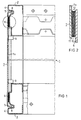
- Figure 1 shows the side area of a control cabinet in section.
- FIG. 1 A detail marked with a circle in FIG. 1 is shown enlarged in FIG.
- FIG. 3 shows a control cabinet in a perspective view.
- FIG. 4 shows a panel for the door of the control cabinet according to FIG. 3 in the folded-up state.
- FIG. 5 shows schematically and enlarged the application of a metal strip to a scaffold or a cover as an adhesive base for a conductive adhesive system.
- FIG. 6 shows the arrangement according to FIG. 1 when a protective film is removed.
- FIG. 7 also shows schematically and enlarged the application of a metal band and a band of an adhesive system to a frame or a cover with a covering lacquer and powder coating.
- the section through the side wall area of a control cabinet 1 is shown shortened in FIG. 1 by an interruption in height.
- An upper scaffold element 2 and a lower, mirror-image scaffold element 3 correspond in profile to the scaffold elements described in DE-A-39 20 353.
- the scaffolding elements 2 and 3 starting from an outer partial surface 4, have a retraction 5 and a further partial surface 6 arranged recessed relative to the partial surface 4.
- the bands of an adhesive system are attached to the partial surfaces 6 of the framework elements 2 and 3 and the opposite inner surfaces 7a of the cover 7.
- the structure of the adhesive system can be seen in more detail on the basis of the region shown enlarged in FIG. 2, which is surrounded by a dash-dotted circle in FIG.
- a band 10 is attached to the partial surface 6 and a band 11 is attached to the opposite surface of the side wall 7.
- These are preferably the strip-shaped tapes of a known adhesive system based on the Velcro principle. It is basically irrelevant which part of the loop part and which part of the hooking part is attached.
- the tapes 10 and 11 are also attached in a known manner by means of self-adhesive adhesive layers.
- Such adhesive layers 12 are shown schematically in FIG. 2.
- FIGS. 1 and 2 An arrangement corresponding to FIGS. 1 and 2 can also be used analogously for fastening a front-side plinth panel of a control cabinet.
- the only difference from the application in the area of the side wall of the control cabinet is the dimensions and the position Of the parts.
- a base panel 16 is shown in FIG. 3.
- the advantageous properties of the fastening of covers described include, in particular, that the outer surface of the covers is not interrupted by fastening elements. Although this could also be achieved with a fastening from the inside of the control cabinet, this would only require a great deal of work due to the unfavorable accessibility of the fastening points. A removal of cover parts fastened in this way would then no longer be possible with the control cabinet fully removed because there is no longer any access to the fastening elements.
- the door 21 of a cabinet 20 is provided at the upper edge with a decorative strip 22, which can itself be provided with a label and which at the same time to protect a label attached to the door 21, for. B. can serve a nameplate.
- the decorative strip 22 is of an angular design and accordingly has a front leg 23 and one for Rest on a bevel 24 of the door 21 provided legs 25.
- the bands 26 and 27 of an adhesive system of the type described are attached. This makes it possible to release the liability by lifting the trim strip 22 in the direction of the arrow 28 and to read the lettering underneath.
- the decorative strip 22 moves hinge-like to its starting position, in which the lettering on the door 21 is covered.
- FIGS. 5 and 6 in which a sheet metal part 30 is shown, which can be part of a framework or a cover.
- a thin metal strip 31 is applied, for. B. a tinned thin copper tape.
- An electrically conductive self-adhesive layer 32 fastens the metal strip 31 and at the same time ensures the electrical connection to the sheet metal part 30.
- the metal strip is covered with a removable protective film 33.
- the protective film 33 is narrower than the metal strip 31, so that edge strips 34 remain uncovered. If the arrangement described is now provided with a corrosion-resistant coating 35 of the type mentioned, the metal strip 31 and its protective film 33 are also covered by the coating 35, as shown in FIG. 5.
- the protective film 33 can now be removed, the coating 35 tearing open.
- the edge strips 34 of the metal strip 31, however, remain covered by the coating 35, so that in particular the laterally exposed areas of the adhesive layer 32 and the bare metal surface of the sheet metal part 30 located underneath remain protected.
- Figure 6 shows this state.
- a metal strip 31 is first attached to the bare metal surface of the sheet metal part 30 by means of a self-adhesive adhesive layer 32.
- a tape 36 of a conductive adhesive system is now applied to the metal tape 31 by means of a further self-adhesive conductive adhesive layer 37.
- a carrier tape 40 which is wider than the actual adhesion-promoting layer 41, is essential for the tape 36.
- the adhesion-promoting layer 41 is covered by a protective film 42 which extends down to the carrier tape 40, but leaves edge strips 43 of the latter free.
- a continuous layer 44 is formed, which can be removed locally by pulling off the protective film 42. As a result, essentially only the adhesion-promoting layer 41 of the band 36 is exposed. The transitions from the sheet metal part 30 to the metal strip 31 and from this to the carrier strip 40 remain protected against corrosive and other influences.
Abstract
Description
Zur Verbindung von Teilen von Kleidungsstücken oder von Schuhwerk sind textile Haftverschlüsse auf der Basis von Klettverschlußelementen bekannt. Ferner ist es bekannt, derartige Klettverschlußelemente auch zur Befestigung starrer Körper auf festen Unterlagen oder Wandflächen zu verwenden
(DE-A-40 12 613, DE-A-40 07 586).Textile fasteners based on Velcro fastener elements are known for connecting parts of clothing or footwear. It is also known to use Velcro fasteners of this type also for fastening rigid bodies to solid supports or wall surfaces
(DE-A-40 12 613, DE-A-40 07 586).
Der Erfindung liegt die Aufgabe zugrunde, Teile elektrischer Schaltschränke oder aus solchen Schaltschränken bestehender Schaltanlagen rationeller zu befestigen, als dies bisher durch Schrauben, Drehriegel oder ähnliche Elemente erfolgt.The invention has for its object to more efficiently attach parts of electrical cabinets or switchgear cabinets consisting of such cabinets than has previously been done by screws, locking bolts or similar elements.
Gemäß der Erfindung wird diese Aufgabe durch Anwendung eines Haftsystems gelöst, bestehend aus zwei aufeinanderlegbaren streifenförmigen und an den zu verbindenden Bauteilen fest anzubringenden Bändern, die eine Vielzahl von flexiblen und miteinander lösbar haftend in Eingriff zu bringenden Elementen aufweisen, zur Befestigung von äußeren abdeckenden Bauteilen eines ein Gerüst aufweisenden Schaltschrankes. Über die Vereinfachung der Befestigung solcher Bauteile hinausgehend werden durch die Erfindung auch wesentliche technische Vorteile erreicht. Insbesondere wirkt die flächenhafte oder auch nur streifenförmige Befestigung der Bauteile einer Neigung zu Schwingungen entgegen, wie sie gerade in Schaltschränken oder Schaltanlagen unter dem Einfluß magnetischer Streufelder oder der vom Betrieb von Schaltgeräten ausgehenden Erschütterungen auftreten können. Ferner läßt sich bei geeigneter Anbringung der streifenförmigen Bänder des Haftsystems eine Abdichtung erzielen. Auch für eine elektrische Verbindung zwischen einem Schrank- oder Anlagengestell und abdeckenden Bauteilen kann gesorgt werden, wenn ein metallisiertes oder metallhaltiges oder auf eine andere Art leitfähig eingestelltes (z. B. durch Graphit) Haftsystem eingesetzt wird, wie dies beispielsweise durch die DE-A-34 03 258 bekannt geworden ist.According to the invention, this object is achieved by using an adhesive system consisting of two strips which can be placed one on top of the other and which are to be fixedly attached to the components to be connected and which have a large number of flexible elements which can be releasably brought into engagement with one another for fastening outer covering components a control cabinet with scaffolding. In addition to simplifying the fastening of such components, significant technical advantages are also achieved by the invention. In particular, the flat or even strip-shaped fastening of the components counteracts a tendency to vibrate, as can occur especially in switch cabinets or switchgear under the influence of magnetic stray fields or the vibrations emanating from the operation of switching devices. Furthermore, a seal can be achieved with a suitable attachment of the strip-shaped strips of the adhesive system. An electrical connection between a cabinet or system frame and covering components can also be provided if a metallized or metal-containing one or is used in a different way with a conductive system (e.g. by means of graphite), as has become known, for example, from DE-A-34 03 258.
Im Rahmen der erfindungsgemäßen Anwendung kann das Bauteil beispielsweise eine Seitenwand, eine Rückwand oder ein Dachblech eines Schaltschrankes sein. Eine solche Seitenwand ist verhältnismäßig großflächig und bedarf daher bei dem üblichen Aufbau eines Schaltschrankes einer Vielzahl von Befestigungselementen. Diese können durch das Haftsystem vorteilhaft ersetzt werden.In the context of the application according to the invention, the component can be, for example, a side wall, a rear wall or a roof plate of a control cabinet. Such a side wall is relatively large and therefore requires a large number of fastening elements in the usual construction of a control cabinet. These can be advantageously replaced by the adhesive system.
Ferner kann im Rahmen der erfindungsgemäßen Anwendung das Bauteil eine einen Sockel des Schaltschrankes frontseitig verschließende Abdeckung sein. In diesem Fall wirkt es sich besonders günstig aus, daß die frontseitige Abdeckung ohne Lösen von Befestigungselementen abnehmbar ist, jedoch nur durch Aufbringen einer beträchtlichen Kraft.Furthermore, in the context of the application according to the invention, the component can be a cover which closes a base of the control cabinet at the front. In this case, it has a particularly favorable effect that the front cover can be removed without loosening the fastening elements, but only by exerting a considerable force.
Diese vorstehend erläuterten Anwendungen eines Haftsystems sind besonders in der Form vorteilhaft, daß das eine Band des Haftsystems nahe einem abgekanteten Rand des Bauteils und das zugehörige weitere Band an gegenüberliegenden Teilflächen mehrfach abgewinkelter, einen Rahmen bildender Gerüstelemente befestigt ist. Ein Beispiel für ein geeignetes Gerüstelement ist der DE-A-39 20 353 zu entnehmen.These applications of an adhesive system explained above are particularly advantageous in the form that one band of the adhesive system is fastened near a folded edge of the component and the associated further band is attached to opposite partial surfaces of multi-angled scaffolding elements which form a frame. An example of a suitable scaffolding element can be found in DE-A-39 20 353.
Ferner ist das Haftsystem in der Weise einsetzbar, daß das Bauteil eine die Frontseite einer Tür des Schaltschrankes teilweise abdeckende Blende ist. In diesem Zusammenhang kann die Blende im Querschnitt winkelförmig ausgebildet sein und das eine Band des Haftsystems kann an einer oberen Abkantung der Tür und das andere Band an einem auf der Abkantung aufliegenden Schenkel der Blende befestigt sein. Auf diese Weise ist es möglich, die Blende anzuheben, um eine darunter geschützt angebracht Beschriftung abzulesen. Beim Loslassen gelangt die Blende wieder in die Ausgangsstellung, in der die Beschriftung verdeckt ist.Furthermore, the adhesive system can be used in such a way that the component is a panel that partially covers the front of a door of the control cabinet. In this connection, the panel can be designed to be angular in cross-section and one band of the adhesive system can be attached to an upper edge of the door and the other band to a leg of the panel resting on the edge. In this way it is possible to raise the panel to read a label that is protected underneath. When you let go the panel returns to the starting position, in which the lettering is hidden.
In allen genannten Fällen ist es vorteilhaft, wenn die Gewichtskraft eines abdeckenden Bauteils durch formschlüssig zusammenwirkende Elemente des Bauteils und des Gerüstes des Schaltschrankes aufgenommen ist. Das Haftsystem wird auf diese Weise nur mit einer Haltekraft beansprucht.In all the cases mentioned, it is advantageous if the weight of a covering component is absorbed by form-fittingly interacting elements of the component and the frame of the control cabinet. In this way, the adhesive system is only subjected to a holding force.
Die Erfindung umfaßt ferner zwei Verfahren zur Anwendung eines Haftsystems der vorstehend erläuterten Art zur lösbaren Befestigung von Abdeckungen an dem Gerüst eines Schaltschrankes. Nach dem ersten dieser Verfahren sind folgende Schritte vorgesehen:
- a) auf metallisch blanke Flächen von Blechteilen des Gerüstes wird ein korrosionsbeständiges Metallband mittels einer elektrisch leitenden selbstklebenden Haftschicht befestigt, wobei die gegenüberliegende Seite des Metallbandes durch eine abziehbare Schutzfolie bedeckt ist, die schmaler als das Metallband ist und zwei Randstreifen des Metallbandes freiläßt,
- b) das Gerüst wird einschließlich der Metallbänder und ihrer Schutzfolien mit einer korrosionsbeständigen Beschichtung versehen,
- c) die Verfahrensschritte a) und b) werden sinngemäß auf die an dem Gerüst anzubringenden Abdeckungen angewendet,
- d) die Schutzfolien der Metallbänder mitsamt der darauf abgeschiedenen Beschichtung werden entfernt,
- e) auf die Metallbänder werden die Bänder des Haftsystems mittels ihrer selbstklebenden Haftschichten aufgebracht,
- f) die Abdeckungen werden durch Aufeinanderlegen der Bänder des Haftsystems an dem Gerüst befestigt.
- a) a corrosion-resistant metal band is attached to bare metal parts of the scaffolding by means of an electrically conductive self-adhesive adhesive layer, the opposite side of the metal band being covered by a removable protective film which is narrower than the metal band and leaves two edge strips of the metal band free,
- b) the framework, including the metal strips and their protective films, is provided with a corrosion-resistant coating,
- c) process steps a) and b) are applied analogously to the covers to be attached to the scaffold,
- d) the protective films of the metal strips, including the coating deposited thereon, are removed,
- e) the tapes of the adhesive system are applied to the metal strips by means of their self-adhesive adhesive layers,
- f) the covers are attached to the frame by laying the tapes of the adhesive system on top of each other.
Wesentlich ist hierbei die Herstellung einer durchgehenden elektrischen Verbindung von dem Gerüst über die Elemente des Haftsystems bis zu den Abdeckungen unter gleichzeitiger Einbeziehung der Metallbänder in den Korrosionsschutz des Gerüstes und der Abdeckungen.What is essential here is the establishment of a continuous electrical connection from the scaffold via the elements of the adhesive system to the covers, with the simultaneous inclusion of the metal strips in the corrosion protection of the Scaffolding and the covers.
Nach dem zweiten erwähnten Verfahren sind folgende Schritte vorgesehen:
- a) auf metallisch blanke Flächen von Blechteilen des Gerüstes wird ein korrosionsbeständiges Metallband mittels einer elektrisch leitenden selbstklebenden Haftschicht befestigt,
- b) auf das Metallband wird mittels einer elektrisch leitfähigen selbstklebenden Haftschicht ein Band des Haftsystems aufgebracht, wobei die eigentliche haftvermittelnde Schicht des Bandes schmaler als das Trägerband der haftvermittelnden Schicht und das Trägerband schmaler als das Metallband bemessen ist und wobei ferner die haftvermittelnde Schicht und anschließende Bereiche des Trägerbandes unter Freilassung von Randstreifen von einer Schutzfolie bedeckt sind,
- c) das Gerüst wird einschließlich der darauf befindlichen Metallbänder und Bänder des Haftsystems mit einer korrosionsbeständigen Beschichtung versehen,
- d) die Verfahrenschritte a), b) und c) werden sinngemäß auf dem Gerüst anzubringende Abdeckungen angewendet,
- e) die Schutzfolien werden von den Bändern des Haftsystems abgezogen und
- f) die Abdeckungen werden durch Aufeinanderlegen der Bänder des Haftsystems an dem Gerüst befestigt.
- a) a corrosion-resistant metal band is attached to bare metal parts of sheet metal parts of the scaffolding by means of an electrically conductive, self-adhesive layer,
- b) a tape of the adhesive system is applied to the metal tape by means of an electrically conductive self-adhesive adhesive layer, the actual adhesive layer of the tape being narrower than the carrier tape of the adhesive layer and the carrier tape being narrower than the metal tape, and furthermore the adhesive layer and subsequent areas of the carrier tape are covered by a protective film with the release of edge strips,
- c) the framework, including the metal strips and strips of the adhesive system located thereon, is provided with a corrosion-resistant coating,
- d) process steps a), b) and c) are applied analogously to covers to be attached to the scaffold,
- e) the protective films are removed from the tapes of the adhesive system and
- f) the covers are attached to the frame by laying the tapes of the adhesive system on top of each other.
Hierbei werden nicht nur die Metallbänder, sondern auch die Trägerbänder des Haftsystems in den Korrosionsschutz einbezogen. Dies verbessert auch die Haltbarkeit der selbstklebenden Haftschichten zwischen dem Metallbändern und dem Gerüst bzw. einer Abdeckung und zwischen den Trägerbändern des Haftsystems und den Metallbändern, weil diese Haftschichten an den Rändern durch die Beschichtung versiegelt sind.Not only the metal strips, but also the carrier strips of the adhesive system are included in the corrosion protection. This also improves the durability of the self-adhesive adhesive layers between the metal strips and the framework or a cover and between the carrier strips of the adhesive system and the metal strips, because these adhesive layers are sealed at the edges by the coating.
Die Erfindung wird im folgenden anhand der in den Figuren dargestellten Ausführungsbeispiele näher erläutert.The invention is explained in more detail below with reference to the exemplary embodiments shown in the figures.
Die Figur 1 zeigt den seitlichen Bereich eines Schaltschrankes im Schnitt.Figure 1 shows the side area of a control cabinet in section.
In der Figur 2 ist eine in der Figur 1 mit einem Kreis markierte Einzelheit vergrößert dargestellt.A detail marked with a circle in FIG. 1 is shown enlarged in FIG.
Die Figur 3 zeigt einen Schaltschrank in einer perspektivischen Ansicht.FIG. 3 shows a control cabinet in a perspective view.
Die Figur 4 zeigt eine Blende für die Tür des Schaltschrankes gemäß der Figur 3 im hochgeklappten Zustand.FIG. 4 shows a panel for the door of the control cabinet according to FIG. 3 in the folded-up state.
Die Figur 5 zeigt schematisch und vergrößert die Aufbringung eines Metallbandes auf ein Gerüst oder eine Abdeckung als Haftgrundlage für ein leitfähiges Haftsystems.FIG. 5 shows schematically and enlarged the application of a metal strip to a scaffold or a cover as an adhesive base for a conductive adhesive system.
Die Figur 6 zeigt die Anordnung gemäß der Figur 1 bei dem Entfernen einer Schutzfolie.FIG. 6 shows the arrangement according to FIG. 1 when a protective film is removed.
In der Figur 7 ist gleichfalls schematisch und vergrößert die Aufbringung eines Metallbandes und eines Bandes eines Haftsystems auf ein Gerüst oder eine Abdeckung mit einer überdeckenden Lack- und Pulverbeschichtung dargestellt.FIG. 7 also shows schematically and enlarged the application of a metal band and a band of an adhesive system to a frame or a cover with a covering lacquer and powder coating.
Der Schnitt durch den Seitenwandbereich eines Schaltschrankes 1 ist in der Figur 1 durch eine Unterbrechung in der Höhe verkürzt dargestellt. Ein oberes Gerüstelement 2 und ein unteres, spiegelbildliches Gerüstelement 3 entsprechen in der Profilierung den in der DE-A-39 20 353 beschriebenen Gerüstelementen. Wie man erkennt, weisen die Gerüstelemente 2 und 3 ausgehend von einer äußeren Teilfläche 4 eine Einziehung 5 und eine gegenüber der Teilfläche 4 zurückgesetzt angeordnete weitere Teilfläche 6 auf. Auf den Gerüstelementen 2 und 3 liegt als abdeckendes äußeres Bauelement eine Seitenwand 7 auf, deren abgekantete Ränder 8 in die Einziehungen 5 eintauchen. An der Innenseite der Seitenwand 7 befestigte Fortsätze, insbesondere die gezeigten Schweißbolzen 9, zentrieren die Seitenwand 7 gegenüber den Gerüstelementen und stützen die Gewichtskraft ab. Auf den Teilflächen 6 der Gerüstelemente 2 und 3 und den gegenüberliegenden Innenflächen 7a der Abdeckung 7 sind die Bänder eines Haftsystems angebracht. Anhand des in der Figur 2 vergrößert dargestellten Bereiches, der in der Figur 1 mit einem strichpunktierten Kreis umgeben ist, läßt sich der Aufbau des Haftsystems näher entnehmen. Wie man erkennt, ist auf der Teilfläche 6 ein Band 10 und auf der gegenüberliegenden Fläche der Seitenwand 7 ein Band 11 angebracht. Es handelt sich dabei vorzugsweise um die streifenförmigen Bänder eines an sich bekannten Haftsystems nach dem Prinzip der Klettbänder. Hierbei ist es grundsätzlich gleichgültig, an welchem der Teile der Schlaufenteil und an welchem Teil der Verhakungsteil angebracht ist. Die Befestigung der Bänder 10 und 11 erfolgt gleichfalls in bekannter Weise mittels selbstklebender Haftschichten. Solche Haftschichten 12 sind in der Figur 2 schematisch dargestellt.The section through the side wall area of a
Bei geeigneter, ununterbrochener Anordnung der Bänder 10 und 11 am gesamten Umfang der Seitenwand 7 wird neben der Befestigung auch eine gute Staubdichtigkeit sowie eine Abdichtung gegen Wasser erzielt. Die Neigung der Seitenwand 7 zu Schwingungen wird gegenüber einer üblichen Befestigung mit Schrauben bedeutend vermindert. Wird ein Haftsystem aus metallisierten oder mit Metallfäden versehenen Bändern 10 und 11 verwendet, so wird bei Anbringung der Seitenwand 7 zwangsläufig auch eine elektrisch leitende Verbindung mit dem Gerüst des Schaltschrankes 1 hergestellt, was bei Schaltschränken aus Gründen des Berührungsschutzes erwünscht ist.With a suitable, uninterrupted arrangement of the
Eine den Figuren 1 und 2 entsprechende Anordnung kann sinngemäß auch zur Befestigung einer frontseitigen Sockelblende eines Schaltschrankes benutzt werden. Unterschiedlich gegenüber der Anwendung im Bereich der Seitenwand des Schaltschrankes sind dabei lediglich die Abmessungen und die Lage der Teile. Eine Sockelblende 16 ist in der Figur 3 gezeigt.An arrangement corresponding to FIGS. 1 and 2 can also be used analogously for fastening a front-side plinth panel of a control cabinet. The only difference from the application in the area of the side wall of the control cabinet is the dimensions and the position Of the parts. A
Der mechanische Widerstand gegen eine Abnahme der Seitenwände oder sonstigen abdeckenden Bauteile ist beträchtlich. Eine unbeabsichtigte Lösung durch betriebliche Einflüsse oder durch eine normale Handhabung eines Schaltschrankes oder einer Schaltanlage ist hierdurch ausgeschlossen. Vielmehr bedarf es der Anwendung spezieller Werkzeuge, um die Abdeckungen zu lösen. Beispielsweise kann ein Werkzeug in den Spalt zwischen einer der Abkantungen 8 der Seitenwand 7 und einem der Gerüstelemente 2 bzw. 3 oder der in der Figur 1 nicht sichtbaren, die hintere bzw. vordere Begrenzung des in der Figur 1 gezeigten Schaltschrankes bildenden Gerüstelemente eingeführt werden. Durch Hebelwirkung läßt sich dann die Seitenwand 7 oder die Sockelblende 16 abdrücken. Ferner können runde oder speziell profilierte Öffnungen in der Seitenwand 7 zum Einführen eines Werkzeuges vorgesehen sein.The mechanical resistance to removal of the side walls or other covering components is considerable. An unintentional solution due to operational influences or through normal handling of a control cabinet or switchgear is excluded. Rather, special tools are required to remove the covers. For example, a tool can be inserted into the gap between one of the
Zu den vorteilhaften Eigenschaften der beschriebenen Befestigung von Abdeckungen gehört insbesondere, daß die Außenfläche der Abdeckungen nicht durch Befestigungselemente unterbrochen ist. Dies wäre zwar auch bei einer Befestigung vom Inneren des Schaltschrankes her zu erreichen, jedoch nur mit großem Arbeitsaufwand aufgrund der ungünstigen Zugänglichkeit der Befestigungsstellen. Eine Abnahme in dieser Weise befestigter Abdeckteile wäre dann bei voll ausgebautem Schaltschrank nicht mehr möglich, weil kein Zugang zu den Befestigungselementen mehr besteht.The advantageous properties of the fastening of covers described include, in particular, that the outer surface of the covers is not interrupted by fastening elements. Although this could also be achieved with a fastening from the inside of the control cabinet, this would only require a great deal of work due to the unfavorable accessibility of the fastening points. A removal of cover parts fastened in this way would then no longer be possible with the control cabinet fully removed because there is no longer any access to the fastening elements.
Gemäß der Figur 3 ist die Tür 21 eines Schaltschrankes 20 am oberen Rand mit einer Zierleiste 22 versehen, die selbst mit einer Beschriftung versehen sein kann und die gleichzeitig zum Schutz einer auf der Tür 21 angebrachten Beschriftung, z. B. eines Typenschildes dienen kann. Wie die Figur 4 zeigt, ist die Zierleiste 22 winkelförmig ausgebildet und besitzt dementsprechend einen frontseitigen Schenkel 23 und einen zur Auflage auf einer Abkantung 24 der Tür 21 vorgesehenen Schenkel 25. An der Abkantung 24 und der gegenüberliegenden Innenseite des Schenkels 25 der Zierleiste 22 sind die Bänder 26 und 27 eines Haftsystems der beschriebenen Art angebracht. Dadurch ist es möglich, die Haftung durch Anheben der Zierleiste 22 in Richtung des Pfeiles 28 zu Lösen und die darunter angebrachte Beschriftung zu lesen. Beim Loslassen gelangt die Zierleiste 22 scharnierartig in ihre Ausgangslage, in der die auf der Tür 21 befindliche Beschriftung abgedeckt ist.According to Figure 3, the
Wie bereits erwähnt, kann es erwünscht sein, daß Abdeckteile eines Schaltschrankes beim Ansetzen an das Gerüst ohne jede zusätzliche Maßnahme in elektrisch leitende Verbindung mit dem Gerüst gelangen. Zwar sind Hafsysteme mit leitfähigen Bändern und leitfähigen selbstklebenden Haftschichten bekannt, doch wird durch die Anwendung nicht unmittelbar die gewünschte leitende Verbindung erzielt. Dies hängt mit dem notwendigen Korrosionsschutz der Gerüste und Abdeckteile zusammen, der nicht nur örtlich aufgebracht werden kann. Vielmehr ist es erforderlich, Gerüste und Abdeckungen als Ganzes zu lackieren oder mit einer Pulverbeschichtung zu versehen. Diese Beschichtungen verhindern das Entstehen einer elektrisch leitfähigen Verbindung zwischen dem Gerüst oder der Abdeckung und leitfähigen Bändern eines Haftsystems. Im folgenden werden zwei Verfahren beschrieben, mit denen diese Schwierigkeiten behoben werden.As already mentioned, it may be desirable for cover parts of a control cabinet to come into an electrically conductive connection with the scaffold without any additional measures when it is attached to the scaffold. Adhesive systems with conductive tapes and conductive self-adhesive adhesive layers are known, but the desired conductive connection is not directly achieved by the application. This is related to the necessary corrosion protection of the scaffolding and cover parts, which cannot only be applied locally. Rather, it is necessary to paint scaffolding and covers as a whole or to provide them with a powder coating. These coatings prevent the formation of an electrically conductive connection between the framework or the cover and conductive tapes of an adhesive system. The following describes two methods to overcome these difficulties.
Zur Erläuterung des ersten der beiden Verfahren wird auf die Figuren 5 und 6 verwiesen, in denen ein Blechteil 30 gezeigt ist, das Bestandteil eines Gerüstes oder einer Abdeckung sein kann.To explain the first of the two methods, reference is made to FIGS. 5 and 6, in which a
Auf das zunächst metallisch blanke Blechteil 30 wird ein dünnes Metallband 31 aufgebracht, z. B. ein verzinntes dünnes Kupferband. Eine elektrisch leitende selbstklebende Haftschicht 32 befestigt das Metallband 31 und sorgt zugleich für die elektrische Verbindung mit dem Blechteil 30. Auf der Außenseite ist das Metallband mit einer abziehbaren Schutzfolie 33 bedeckt. Die Schutzfolie 33 ist schmaler als das Metallband 31, so daß Randstreifen 34 unbedeckt bleiben. Wird nun die beschriebene Anordnung mit einer korrosionsbeständigen Beschichtung 35 der erwähnten Art versehen, so werden auch das Metallband 31 und seine Schutzfolie 33 von der Beschichtung 35 bedeckt, wie dies die Figur 5 zeigt.On the initially metallic blank
In einem weiteren Schritt kann nun die Schutzfolie 33 abgezogen werden, wobei die Beschichtung 35 aufreißt. Die Randstreifen 34 des Metallbandes 31 bleiben jedoch von der Beschichtung 35 bedeckt, so daß insbesondere die seitlich freiliegenden Bereiche der Haftschicht 32 und die darunter befindliche blanke Metallfläche des Blechteiles 30 geschützt bleiben. Diesen Zustand zeigt die Figur 6.In a further step, the
Bei dem anhand der Figur 7 zu erläuternden zweiten Verfahren ist eine noch weitergehende Integration der Komponenten des Haftsystems vorgesehen. Übereinstimmend mit der Figur 5 wird zunächst ein Metallband 31 mittels einer selbstklebenden Haftschicht 32 auf der blanken Metallfläche des Blechteiles 30 angebracht. Auf das Metallband 31 wird nun ein Band 36 eines leitfähigen Haftsystems aufgebracht, und zwar mittels einer weiteren selbstklebenden leitfähigen Haftschicht 37. Wesentlich für das Band 36 ist ein Trägerband 40, das breiter als die eigentliche haftvermittelnde Schicht 41 bemessen ist. Ferner ist die haftvermittelnde Schicht 41 durch eine Schutzfolie 42 bedeckt, die bis zu dem Trägerband 40 hinabreicht, jedoch Randstreifen 43 desselben freiläßt. Bei der anschließenden Beschichtung entsteht eine durchgehende Schicht 44, die durch Abziehen der Schutzfolie 42 örtlich entfernt werden kann. Hierdurch wird im wesentlichen nur die haftvermittelnde Schicht 41 des Bandes 36 freigelegt. Die Übergänge von dem Blechteil 30 zu dem Metallband 31 und von diesem zu dem Trägerband 40 bleiben gegen korrosive und sonstige Einflüsse geschützt.In the second method to be explained with reference to FIG. 7, an even more extensive integration of the components of the adhesive system is provided. In accordance with FIG. 5, a
Nach dem beschriebenen Abziehen der Schutzfolie 37 können entsprechend ausgerüstete Teile eines Schaltschrankes lösbar zusammengefügt werden.After the
Claims (9)
Applications Claiming Priority (2)
| Application Number | Priority Date | Filing Date | Title |
|---|---|---|---|
| DE4201296 | 1992-01-16 | ||
| DE19924201296 DE4201296C2 (en) | 1992-01-16 | 1992-01-16 | Use of an adhesive system |
Publications (1)
| Publication Number | Publication Date |
|---|---|
| EP0551971A1 true EP0551971A1 (en) | 1993-07-21 |
Family
ID=6449814
Family Applications (1)
| Application Number | Title | Priority Date | Filing Date |
|---|---|---|---|
| EP93250003A Withdrawn EP0551971A1 (en) | 1992-01-16 | 1993-01-06 | Use of a fastening system |
Country Status (2)
| Country | Link |
|---|---|
| EP (1) | EP0551971A1 (en) |
| DE (1) | DE4201296C2 (en) |
Cited By (4)
| Publication number | Priority date | Publication date | Assignee | Title |
|---|---|---|---|---|
| WO1998023012A1 (en) * | 1996-11-19 | 1998-05-28 | Rittal-Werk Rudolf Loh Gmbh & Co. Kg | Switching cabinet |
| EP0902515A1 (en) * | 1997-09-15 | 1999-03-17 | Schneider Electric Sa | Electrical cabinet with identification strip |
| DE202007007306U1 (en) * | 2007-05-23 | 2008-05-21 | Meusburger Georg Gmbh & Co. | Cover plate for the ejector package of an injection mold |
| EP2128944A1 (en) * | 2008-10-27 | 2009-12-02 | ABB Technology AG | A method of producing an encapsulated electric apparatus and such an encapsulated electric apparatus |
Families Citing this family (5)
| Publication number | Priority date | Publication date | Assignee | Title |
|---|---|---|---|---|
| DE19500739C2 (en) * | 1995-01-12 | 1996-12-12 | Wilhelm Bader | Cabinet for plant or machine construction |
| DE19536904C1 (en) * | 1995-10-04 | 1996-11-21 | Loh Kg Rittal Werk | Switchgear housing with frame and wall elements |
| DE102005061336A1 (en) * | 2005-12-21 | 2007-06-28 | Rohde & Schwarz Gmbh & Co. Kg | Electromagnetic interferences shielding housing for electronic device, has housing parts, and slot that is closed in electromagnetically tight manner between housing parts by Velcro fastener unit |
| DE102006047974A1 (en) * | 2006-10-10 | 2008-04-17 | Siemens Ag | electric component |
| DE102007001656B3 (en) | 2007-01-11 | 2008-07-24 | Howaldtswerke-Deutsche Werft Gmbh | Submarine with a control cabinet |
Citations (6)
| Publication number | Priority date | Publication date | Assignee | Title |
|---|---|---|---|---|
| US3571999A (en) * | 1969-07-02 | 1971-03-23 | John G Downing | Knockdown display |
| DE2455240A1 (en) * | 1974-11-22 | 1976-05-26 | Bolle Friedrich Adolf Dipl Ing | Structure for assembling construction elements - in which a junction of flexible links are locked together by hooks |
| US3971608A (en) * | 1975-04-17 | 1976-07-27 | Gans Charles C | Knock-down drawer unit |
| US4936410A (en) * | 1988-09-19 | 1990-06-26 | Howell Les P | Speaker cover |
| US4966421A (en) * | 1987-07-24 | 1990-10-30 | Craig Mengel | Method of and structure for the joining of substantially rigid parts together |
| DE4019121A1 (en) * | 1989-06-13 | 1991-01-10 | Suzuki Motor Co | Insulation of bonnet of motor vehicle - is attached by screws or rivets to bonnet reinforcing member |
Family Cites Families (7)
| Publication number | Priority date | Publication date | Assignee | Title |
|---|---|---|---|---|
| DE3343098A1 (en) * | 1983-11-29 | 1985-06-05 | Dieter 7930 Ehingen Giessler | Toy furniture |
| DE3403258A1 (en) * | 1984-01-31 | 1985-08-01 | Gottlieb Binder GmbH & Co, 7038 Holzgerlingen | TEXTILE AREA LOCKER |
| DE3911017A1 (en) * | 1989-04-05 | 1990-10-11 | Ensslin Gmbh & Co | Laboratory or workshop furniture |
| DE3913060A1 (en) * | 1989-04-21 | 1990-10-25 | Klaus Schueler | Clip holding single sheet of paper - has arm with hooked strip attaching clip to suitable support |
| DE3920353A1 (en) * | 1989-06-19 | 1990-12-20 | Siemens Ag | SCAFFOLDING FOR A CONTROL CABINET FROM MULTIPLE ANGLED PROFILE ELEMENTS WITH SINGLE-SIDED OPEN HOLLOW PROFILE |
| DE4007586A1 (en) * | 1990-03-09 | 1991-09-12 | Sto Poraver Gmbh | METHOD AND DEVICE FOR APPLYING TILE, PLASTER OR LACQUER COATINGS OR. DECORATIVE COVERINGS ON WALLS, CEILINGS OR THE LIKE |
| DE4012613A1 (en) * | 1990-04-20 | 1991-10-24 | Peter Josef Korzilius Soehne G | Ceramic slab-laying method - uses hook-clasp fastener on rear surface engaging with velvet on base surface |
-
1992
- 1992-01-16 DE DE19924201296 patent/DE4201296C2/en not_active Expired - Fee Related
-
1993
- 1993-01-06 EP EP93250003A patent/EP0551971A1/en not_active Withdrawn
Patent Citations (7)
| Publication number | Priority date | Publication date | Assignee | Title |
|---|---|---|---|---|
| US3571999A (en) * | 1969-07-02 | 1971-03-23 | John G Downing | Knockdown display |
| DE2455240A1 (en) * | 1974-11-22 | 1976-05-26 | Bolle Friedrich Adolf Dipl Ing | Structure for assembling construction elements - in which a junction of flexible links are locked together by hooks |
| US3971608A (en) * | 1975-04-17 | 1976-07-27 | Gans Charles C | Knock-down drawer unit |
| US4966421A (en) * | 1987-07-24 | 1990-10-30 | Craig Mengel | Method of and structure for the joining of substantially rigid parts together |
| US4966421B1 (en) * | 1987-07-24 | 1993-04-06 | Mengel Craig | |
| US4936410A (en) * | 1988-09-19 | 1990-06-26 | Howell Les P | Speaker cover |
| DE4019121A1 (en) * | 1989-06-13 | 1991-01-10 | Suzuki Motor Co | Insulation of bonnet of motor vehicle - is attached by screws or rivets to bonnet reinforcing member |
Cited By (6)
| Publication number | Priority date | Publication date | Assignee | Title |
|---|---|---|---|---|
| WO1998023012A1 (en) * | 1996-11-19 | 1998-05-28 | Rittal-Werk Rudolf Loh Gmbh & Co. Kg | Switching cabinet |
| AU725964B2 (en) * | 1996-11-19 | 2000-10-26 | Rittal-Werk Rudolf Loh Gmbh & Co. Kg | Switchgear cabinet |
| US6211466B1 (en) | 1996-11-19 | 2001-04-03 | Rittal-Werk Rudolf Loh Gmbh & Co. Kg | Switching cabinet |
| EP0902515A1 (en) * | 1997-09-15 | 1999-03-17 | Schneider Electric Sa | Electrical cabinet with identification strip |
| DE202007007306U1 (en) * | 2007-05-23 | 2008-05-21 | Meusburger Georg Gmbh & Co. | Cover plate for the ejector package of an injection mold |
| EP2128944A1 (en) * | 2008-10-27 | 2009-12-02 | ABB Technology AG | A method of producing an encapsulated electric apparatus and such an encapsulated electric apparatus |
Also Published As
| Publication number | Publication date |
|---|---|
| DE4201296A1 (en) | 1993-07-22 |
| DE4201296C2 (en) | 1995-10-19 |
Similar Documents
| Publication | Publication Date | Title |
|---|---|---|
| DE4127468C1 (en) | ||
| DE4223322C1 (en) | ||
| DE2608921A1 (en) | SHIELDING STRIPS FOR ELECTROMAGNETIC INTERFERENCE | |
| DE2134815A1 (en) | Housing arrangement for electrical devices for shielding against electrostatic and magnetostatic radiation | |
| DE19700065C2 (en) | Filter fan or outlet filter | |
| DE3328386A1 (en) | HIGH-FREQUENCY DENSITY SHIELDING OF AREA PARTS | |
| EP2638606A2 (en) | Electrical switch cabinet | |
| DE4311246C1 (en) | Housing for electronic equipment with HF sealing - provided by formed leaf spring contact clips that are located of ribs of frame bars and engage fill in panels | |
| DE1195829C2 (en) | ELECTRICAL EQUIPMENT CHASSIS AND PROCESS FOR ITS MANUFACTURING | |
| DE3635866C2 (en) | Record holder | |
| DE2424722B2 (en) | Housing for electrical measurement and communication technology devices | |
| EP0551971A1 (en) | Use of a fastening system | |
| DE7903580U1 (en) | MAGAZINE FOR MAGNETIC TAPE CASSETTES | |
| DE69817259T2 (en) | Electronic shield and printed circuit board with such a shield | |
| EP0838987B1 (en) | Electronic rack | |
| DE19644414C1 (en) | Electromagnetically screened printed circuit card assembly package for pluggable modules | |
| DE19548723A1 (en) | Housing for receiving electronic components | |
| DE19908889A1 (en) | Electronics housing with improved sealing and shielding device and method for producing the same | |
| EP0269126B1 (en) | Screened case | |
| DE1690003C3 (en) | Dismountable box for storing electrical devices | |
| DE4207308C2 (en) | Method of manufacturing a sheet metal housing | |
| DE4402235C2 (en) | Protective cover | |
| DE19629230A1 (en) | Electronic device and shielding molding for an electronic device | |
| DE2300576A1 (en) | CONNECTION BETWEEN TWO METAL PARTS SHIELDING AGAINST ELECTROMAGNETIC RADIATION | |
| DE4309084A1 (en) | Interference-radiation-screened housing |
Legal Events
| Date | Code | Title | Description |
|---|---|---|---|
| PUAI | Public reference made under article 153(3) epc to a published international application that has entered the european phase |
Free format text: ORIGINAL CODE: 0009012 |
|
| AK | Designated contracting states |
Kind code of ref document: A1 Designated state(s): AT DE FR GB IT SE |
|
| 17P | Request for examination filed |
Effective date: 19931206 |
|
| 17Q | First examination report despatched |
Effective date: 19950714 |
|
| STAA | Information on the status of an ep patent application or granted ep patent |
Free format text: STATUS: THE APPLICATION HAS BEEN WITHDRAWN |
|
| 18W | Application withdrawn |
Withdrawal date: 19960129 |