EP0553566A1 - Horizontal well completion method - Google Patents
Horizontal well completion method Download PDFInfo
- Publication number
- EP0553566A1 EP0553566A1 EP92311746A EP92311746A EP0553566A1 EP 0553566 A1 EP0553566 A1 EP 0553566A1 EP 92311746 A EP92311746 A EP 92311746A EP 92311746 A EP92311746 A EP 92311746A EP 0553566 A1 EP0553566 A1 EP 0553566A1
- Authority
- EP
- European Patent Office
- Prior art keywords
- conduit
- particulate material
- resin composition
- cement
- well bore
- Prior art date
- Legal status (The legal status is an assumption and is not a legal conclusion. Google has not performed a legal analysis and makes no representation as to the accuracy of the status listed.)
- Ceased
Links
Images

Classifications
-
- E—FIXED CONSTRUCTIONS
- E21—EARTH DRILLING; MINING
- E21B—EARTH DRILLING, e.g. DEEP DRILLING; OBTAINING OIL, GAS, WATER, SOLUBLE OR MELTABLE MATERIALS OR A SLURRY OF MINERALS FROM WELLS
- E21B43/00—Methods or apparatus for obtaining oil, gas, water, soluble or meltable materials or a slurry of minerals from wells
- E21B43/11—Perforators; Permeators
- E21B43/116—Gun or shaped-charge perforators
-
- E—FIXED CONSTRUCTIONS
- E21—EARTH DRILLING; MINING
- E21B—EARTH DRILLING, e.g. DEEP DRILLING; OBTAINING OIL, GAS, WATER, SOLUBLE OR MELTABLE MATERIALS OR A SLURRY OF MINERALS FROM WELLS
- E21B33/00—Sealing or packing boreholes or wells
- E21B33/10—Sealing or packing boreholes or wells in the borehole
- E21B33/13—Methods or devices for cementing, for plugging holes, crevices, or the like
- E21B33/14—Methods or devices for cementing, for plugging holes, crevices, or the like for cementing casings into boreholes
-
- E—FIXED CONSTRUCTIONS
- E21—EARTH DRILLING; MINING
- E21B—EARTH DRILLING, e.g. DEEP DRILLING; OBTAINING OIL, GAS, WATER, SOLUBLE OR MELTABLE MATERIALS OR A SLURRY OF MINERALS FROM WELLS
- E21B43/00—Methods or apparatus for obtaining oil, gas, water, soluble or meltable materials or a slurry of minerals from wells
- E21B43/02—Subsoil filtering
- E21B43/025—Consolidation of loose sand or the like round the wells without excessively decreasing the permeability thereof
-
- E—FIXED CONSTRUCTIONS
- E21—EARTH DRILLING; MINING
- E21B—EARTH DRILLING, e.g. DEEP DRILLING; OBTAINING OIL, GAS, WATER, SOLUBLE OR MELTABLE MATERIALS OR A SLURRY OF MINERALS FROM WELLS
- E21B43/00—Methods or apparatus for obtaining oil, gas, water, soluble or meltable materials or a slurry of minerals from wells
- E21B43/02—Subsoil filtering
- E21B43/04—Gravelling of wells
Definitions
- the present invention relates to a method of completing portions of a well bore and conduit which are positioned substantially horizontally in a hydrocarbon containing subterranean formation.
- Horizontal wells are those well wherein at least the lower end portion of the well bore is positioned substantially horizontally in a hydrocarbon containing subterranean formation.
- the horizontal portions of such wells have been completed "open hole” when the material forming the subterranean formation permits and "cased hole” where the subterranean formation is partially or wholly incompetent.
- cased hole completions the casing has been cemented in the substantially horizontal portion of the well bore utilizing impermeable cement.
- a large number of perforations are generally required in order to allow the hydrocarbons from the subterranean formation to readily flow through the impermeable cement and into the interior of the casing.
- the migration of incompetent formation materials, e.g. sand with the hydrocarbons by way of the perforations is often a problem.
- a method of completing a well bore having a conduit disposed therein where at least the lower end portions of the well bore and conduit are positioned substantially horizontally in a subterranean formation comprises the steps of:
- At least the portions of a well bore and a conduit disposed therein, e.g. casing, which are positioned substantially horizontally in a producing formation are completed by first placing a hardenable resin composition coated particulate solid material in the annulus between the sides of the well bore and the conduit therein.
- the hardenable resin composition on the particulate material is then caused to harden which consolidates the particulate material into a hard permeable mass.
- Perforations are next formed in the conduit which are spaced along the horizontal length thereof and divide the conduit into two or more unperforated sections.
- An aqueous cement slurry is then introduced by way of the perforations into the permeable consolidated particulate material surrounding the conduit whereby sections thereof corresponding to the unperforated sections of the conduit are isolated from each other by portions of the cement slurry.
- the cement slurry is allowed to set into hard impermeable masses in the consolidated particulate material, and one or more of the unperforated sections of the conduit are perforated to allow the flow of hydrocarbons through the permeable consolidated particulate material into the interior of the conduit.
- the isolated sections of the permeable consolidated particulate material allow tests and treatments to be performed in selected portions of the producing formation along the length of the substantially horizontal well bore therein.
- the present invention provides an improved method of completing cased hole horizontal wells.
- a well bore having a conduit disposed therein, e.g. casing is completed whereby the portions of the well bore and conduit which are positioned substantially horizontally in a hydrocarbon producing formation are bonded together by a consolidated particulate solid material which is permeable to the flow of hydrocarbons. That is, the consolidated particulate solid material has a hydrocarbon fluid conductivity which approaches the fluid conductivity of the hydrocarbon producing formation.
- the permeable consolidated particulate solid material provides a barrier between perforations in the conduit and the face of the hydrocarbon producing formation which prevents the migration of sand and other incompetent materials from the formation into the conduit.
- cement seals are provided in the permeable consolidated particulate material surrounding the conduit which are spaced along the length thereof whereby the consolidated particulate material is divided into isolated horizontal sections.
- the isolated sections can be separately perforated so that tests and/or treatments can be performed in selected portions of the formation through which the horizontal well bore extends.
- the methods of completing a horizontal well bore as described above comprise the first step of placing a particulate solid material coated with a hardenable resin composition in the annulus between the sides of the substantially horizontal portion of the well bore and the conduit disposed therein. Once placed, the hardenable resin composition is caused to harden which consolidates the particulate material into a hard permeable mass and bonds the conduit to the well bore. A plurality of perforations are next formed in the portion of the conduit surrounded by the consolidated particulate material which are spaced along the length thereof whereby the perforations divide the conduit into two or more unperforated sections.
- aqueous slurry of particulate cement having a high degree of fineness is then introduced into the permeable consolidated particulate material by way of the perforations whereby sections thereof corresponding to the unperforated sections of the conduit are isolated from each other by portions of the cement slurry.
- the cement slurry is allowed to set into hard impermeable masses in the consolidated particulate material.
- one or more of the isolated unperforated horizontal sections of the conduit are perforated in a manner whereby the permeable consolidated particulate material surrounding the conduit is left substantially intact and hydrocarbons without incompetent formation materials flow through the perforations into the conduit.
- the hardenable resin composition coated particulate solid material utilized in accordance with this invention can be any of various types of particulate material coated with any of various hardenable resin compositions.
- the particulate material can be, for example, sand, sintered bauxite, glass particles, and the like.
- the preferred particulate material is sand having a particle size in the range of from about 10 to about 70 mesh, U.S. Sieve Series (apertures 2.00 to 0.210 mm).
- the preferred particulate material size ranges are 10-20 mesh (aperture 2.00 to 0.81 mm), 20-40 mesh (aperture 0.81 to 0.42 mm), 40-60 mesh (aperture 0.42 to 0.25 mm) or 50-70 mesh (aperture 0.297 to 0.210 mm) depending upon the particle size and distribution of formation sand adjacent to which the resin coated sand is to be deposited.
- a preferred hardenable resin composition for coating the particulate material is comprised of a hardenable polyepoxide resin, at least one water immiscible diluent for the resin and a delayed hardening agent for the resin.
- Polyepoxide resins which can be utilized include the condensation products of epichlorohydrin and multiple hydroxy compounds such as resorcinol hydroquinone, glycerine, pentaerythritol, 1,4-butanediol, phloroglucinol, bisphenol A and bisphenol F.
- a particularly suitable and preferred such resin is the condensation resin product of epichlorohydrin and bisphenol A.
- a commercially available such product is marketed by the Shell Chemical Company of Houston, Texas under the tradename EPON 828TM.
- EPON 828TM resin exhibits good temperature stability and chemical resistance, and has a viscosity of about 15,000 centipoises (15 Pas).
- the one or more substantially water immiscible diluents are utilized in the resin composition to adjust the viscosity of the composition to a desired level, generally a level in the range of from about 100 centipoises to about 800 centipoises (0.1 to 0.8 Pas).
- a desired level generally a level in the range of from about 100 centipoises to about 800 centipoises (0.1 to 0.8 Pas).
- two polar organic diluents are used which are miscible with the polyepoxide resin and substantially immiscible with water.
- One of such diluents is preferably reactive with the epoxy resin component and the other diluent is preferably non-reactive.
- the substantially water immiscible reactive diluent is preferably comprised of at least one member selected from the group consisting of butyl glycidyl ether, cresol glycidyl ether, allyl glycidyl ether, phenyl glycidyl ether, and other glycidyl ethers which are miscible with the epoxy resin utilized. Of these, butyl glycidyl ether and cresol glycidyl ether are the most preferred.
- the reactive diluent or diluents are generally present in the resin composition in an amount in the range of from about 2 to about 35 parts by weight per 100 parts by weight of the polyepoxy resin present. Preferably, the reactive diluent is present in the range of from about 15 to about 30, and most preferably, about 28 parts by weight per 100 parts by weight of polyepoxide resin.
- water immiscible non-reactive diluents which can be utilized, one or more selected from the group of ethyl acetate, butyl lactate, ethyl lactate, amyl acetate, ethylene glycol diacetate and propylene glycol diacetate are preferred. Of these, butyl lactate is the most preferred.
- the water immiscible non-reactive diluent is generally included in the resin composition in an amount in the range of from about 4 to about 20 parts by weight per 100 parts by weight of the polyepoxide resin present.
- the non-reactive diluent is present in an amount in the range of from about 8 to about 15, and most preferably about 10 parts by weight per 100 parts by weight of the polyepoxide resin present.
- examples of other diluents which can be utilized are methyl alcohol and other low molecular weight alkanols, tetrahydrofurfuryl methacrylate and ethyl acetate.
- a variety of delayed hardening agents can be used in the resin composition.
- hardening agents include amines, polyamines, amides and polyamides.
- a hardening agent which has been commonly utilized heretofore is methylene dianiline either dissolved in a suitable solvent such as ethyl acetate or in a liquid eutectic mixture of amines diluted with methyl alcohol.
- a preferred hardening agent is comprised of the adduct formed by reacting an aliphatic or cycloaliphatic amine with the condensation reaction product of epichlorohydrin and bisphenol A.
- aliphatic amines While a variety of aliphatic amines can be utilized, preferred amines are those selected from the group consisting of ethylene diamine, triethylene tetramine, tetraethylene pentamine, bis-(p-aminocyclohexyl) methane, the diamines and triamines of cyclopentane and the diamines and triamines of cyclohexane. Of these, triethylene tetramine, 1,2-diaminocyclohexane and 1,4-diaminocyclohexane are preferred with 1,4-diaminocyclohexane being the most preferred.
- the adducts of the aliphatic amines are prepared by reacting a selected amine with the condensation reaction product of epichlorohydrin and bisphenol A.
- the preferred hardening agent i.e., the adduct formed by reacting an aliphatic amine with the condensation reaction product of epichlorohydrin and bisphenol A, is generally included in the resin composition in an amount in the range of from about 20 to about 150 parts by weight per 100 parts by weight of polyepoxy resin.
- the hardening agent is present in an amount in the range of from about 40 to about 90, and most preferably, about 68 parts by weight per 100 parts of polyepoxide resin.
- the hardenable resin composition can also include retarders or accelerators as hardening rate controllers to lengthen or shorten the working and cure times of the resin composition.
- Low molecular weight organic acid ester retarders such as alkyl esters of alkyl acids containing about 2 to 3 carbon atoms can be utilized.
- Suitable accelerators include 2,4,6-trisdimethylaminomethylphenol, the ethyl hexonate salt thereof and weak organic acid such as fumaric, erythorbic, ascorbic, salicylic and maleic acids.
- a retarder or accelerator is utilized, it is generally combined with the resin composition in amounts up to about 10 parts by weight per 100 parts by weight of polyepoxide resin.
- the resin composition also preferably includes a resin to particulate material coupling agent to promote bonding of the resin to the particulate material.
- a preferred such coupling agent is N-beta-(aminoethyl)-gamma-aminopropyltrimethoxysilane.
- the coupling agent generally can be included in the resin composition in an amount from about 0.1 to about 2 parts by weight per 100 parts by weight of polyepoxide resin.
- the preparation of the hardenable resin composition coated particulate solid material and its placement in the well bore, i.e., in the annulus between the sides of the portion of the well bore which is positioned substantially horizontally and the conduit disposed therein, can be accomplished in various ways.
- the resin coated particulate material can be prepared in a batch mixing operation followed by the suspension of the resin composition coated particulate material in a carrier liquid.
- the carrier liquid suspension of the resin coated particulate material can then be pumped within the conduit disposed in the well bore through the open end thereof and into the horizontal portion of the annulus between the well bore and the conduit.
- a more preferred technique for preparing and placing the resin composition coated particulate material is described in United States Patent No. 4,829,100 issued May 9, 1989.
- a consolidatable resin composition coated particulate material is continuously formed and suspended in a gelled aqueous carrier liquid, and the suspension is pumped to the zone where the resin coated particulate material is to be placed.
- substantially continuous streams of a gelled aqueous carrier liquid, uncoated particulate material, a resin composition which will subsequently harden and a surface active agent are admixed whereby the particulate material is continuously coated with resin composition and suspended in the gelled aqueous carrier liquid.
- the suspension is continuously pumped into the subterranean formation or other zone wherein the consolidatable resin composition coated particulate material is to be deposited.
- the suspension of the hardenable resin composition coated particulate material in an aqueous gelled carrier liquid produced in accordance with Patent No. 4,829,100 is comprised of an aqueous liquid, at least one hydratable polysaccharide gelling agent, the above described resin composition, particulate material and one or more surface active agents for promoting the coating of the particulate material with the resin composition.
- the aqueous liquid can be fresh water, brine or sea water.
- a variety of hydratable polysaccharide gelling agents can be utilized having molecular weights in the range of from about 100,000 to 4,000,000, preferably from about 600,000 to 2,400,000.
- the polysaccharide gelling agents are cellulose or guar derivatives.
- the polymers include substituents such as hydroxyethyl to give the necessary water hydration and gel characteristics to produce a clear aqueous gel having a viscosity of at least about 30 centipoises (0.03 Pas) (reading on a Fann V.G. meter at 300 rpm).
- Preferred such polymers include substituted carboxy and hydroxy alkyl cellulose, such as hydroxyethylcellulose and carboxymethylhydroxyethylcellulose, and substituted hydroxyalkylguar, such as hydroxypropylguar.
- the most preferred polysaccharide polymer gelling agent is hydroxypropylguar having a molecular weight in the range of from about 100,000 to about 4,000,000, and having a propylene oxide substitution (MS) of about 0.1 to about 0.7 moles of propylene oxide per mole of mannose and galactose in the guar.
- MS propylene oxide substitution
- the surface active agent for promoting the coating of the particulate material can be one or more cationic surface active agents or one or more non-cationic surface active agents, or one or more of both.
- a non-cationic surface active agent includes a blend of anionic and non-ionic surface active agents.
- Useful cationic surface active agents include the reaction product of an alcohol, epichlorohydrin and triethylenediamine wherein monohydric aliphatic alcohols having in the range of from about 12 to about 18 carbon atoms are reacted with from 2 to 3 moles of epichlorohydrin per mole of alcohol followed by reaction with an excess of triethylenediamine.
- the alcohol-epichlorohydrin reaction product contains an ethoxylation chain having pendent chlorides. The subsequent reaction with triethylenediamine provides a cationic and a tertiary amine functionality to the resulting product.
- the non-cationic surfactants are preferably ethoxylated fatty acids produced by reacting fatty acids containing from about 12 to about 22 carbon atoms with from about 5 to about 20 moles of ethylene oxide per mole of acid, most preferably from about 12 to about 18 moles of ethylene oxide per mole of acid, to produce a mixture of various quantities of ethoxylated acids and unreacted acids.
- one preferred surface active agent is a blend comprised of isopropyl alcohol, the cationic agent described above and the non-cationic agent described above wherein the weight ratio of cationic agent to non-cationic agent in the blend is in the range of from about 0.4 to 1, and preferably about 0.6 parts by weight cationic agent per 1 part by weight non-cationic agent and wherein the weight ratio of isopropyl alcohol to non-cationic agent in the blend is about 1 part by weight alcohol per 1 part by weight non-cationic agent.
- a preferred surface active agent is a blend comprised of alcohol, e.g., amyl alcohol, the cationic agent described above and the non-cationic agent described above wherein the weight ratio of cationic agent to non-cationic agent in the blend is in the range of 0 to 1, and preferably about 0.2 parts by weight cationic agent per 1 part by weight non-cationic agent and wherein the weight ratio of alcohol to non-cationic agent in the blend is about 1 part by weight alcohol per 1 part by weight non-cationic agent.
- alcohol e.g., amyl alcohol
- the cationic agent described above the non-cationic agent described above
- the weight ratio of cationic agent to non-cationic agent in the blend is in the range of 0 to 1, and preferably about 0.2 parts by weight cationic agent per 1 part by weight non-cationic agent and wherein the weight ratio of alcohol to non-cationic agent in the blend is about 1 part by weight alcohol per 1 part by weight non-cationic agent.
- the above-described composition is comprised of resin composition coated particulate material suspended in a gelled aqueous liquid.
- the gelled aqueous liquid preferably contains the polysaccharide polymer utilized in an amount in the range of from about 20 to about 120 lbs (9.1 to 54.5kg) of polymer per 1000 gallons (3.78m3) of water, brine or sea water whereby the gelled aqueous liquid has a viscosity in the range of from about 10 centipoises (0.01Pas) to about 400 centipoises (0.4Pas).
- the gelled aqueous carrier liquid includes from about 30 to about 80 lbs (13.6 to 36.3kg) of gelling agent per 1000 gallons (3.78m3) of water, brine or sea water, and has a viscosity of from about 15 to about 100 centipoises (0.015 to 0.1Pas).
- the gelled aqueous liquid can be crosslinked to increase its viscosity and stability.
- a gel breaker is included in the gelled aqueous liquid to cause it to revert to a relatively thin liquid at the time the resin coated particulate material reaches the location of its placement. While a variety of gel breakers which are well known in the art can be utilized, an oxidative type of breaker such as sodium persulfate is preferred. Such oxidative gel breakers are generally included in the composition in an amount in the range of from about 0.5 pounds (0.23kg) to about 50 pounds (22.7kg) per 1000 gallons (3.78m3) of gelled aqueous carrier liquid, but the particular amount depends on the specific time period required between when the gel breaker is added and when the gel must be broken. Increases in the amount of gel breaker shorten such time period.
- the aqueous cement slurry useful in accordance with the present invention is comprised of water and a fine particulate hydraulic cement which sets into a hard impermeable mass.
- the water can be fresh water, salt water, seawater or brine.
- the particulate hydraulic cement In order for the particulate hydraulic cement to be capable of flowing into the consolidated particulate solid material it must be of a fine particle size.
- a preferred such fine particle size cement is one consisting of particles of cementitous material having diameters no larger than about 30 microns (3x10 ⁇ 5m), preferably no larger than about 17 microns (17x10 ⁇ 6m), and still more preferably no larger than about 11 microns (11x10 ⁇ 6m).
- the distribution of the various sized particles within the cementitious material should be such that 90% of the particles have a diameter not greater than about 25 microns (25x10 ⁇ 6m), preferably about 10 microns (10 ⁇ 5m), and still more preferably about 7 microns (7x10 ⁇ 6m), 50% have a diameter not greater than about 10 microns (10 ⁇ 5m), preferably about 6 microns (6x10 ⁇ 6m), and still more preferably about 4 microns (4x10 ⁇ 6m), and 20% of the particles have a diameter not greater than about 5 microns (5x10 ⁇ 6m), preferably about 3 microns (3x10 ⁇ 6m) and still more preferably about 2 microns (2x10 ⁇ 6m).
- the particle size of the hydraulic cement can be indirectly expressed in terms of the surface area per unit weight of a given sample of the cement. This value, sometimes referred to as Blaine Fineness, can be expressed in units of square centimeters per gram (cm2/gram) and is an indication of the ability of a cement to chemically interact with water and other materials. The activity is believed to increase with increased Blaine Fineness.
- the Blaine Fineness of the hydraulic cement used in accordance with this invention should be no less than about 6000 cm2/gram, preferably greater than about 7000 cm2/gram, more preferably greater than about 10,000 cm2/gram and most preferably greater than about 13,000 cm2/gram.
- Hydraulic cements having the fineness and particle size distribution described above are disclosed in various prior United States patents including U.S. Patent No. 4,761,183 to Clark which discloses slag and mixtures of slag with Portland cement, and U.S. Patent No. 4,160,674 to Sawyer which discloses Portland cement.
- the hydraulic cements can also include fine pozzolan cement and/or fine silica in addition to the slag and/or Portland cement.
- the cements which are preferred for use in accordance with this invention are Portland cement and combinations thereof with slag wherein the quantity of Portland cement included in a mixture of Portland cement and slag can be as low as 10%, but is preferably no less than about 40%, more preferably about 60% and still more preferably about 80%.
- the most preferred cement of the fineness and particle size distribution described above is Portland cement.
- aqueous cement slurries useful herein can be formulated utilizing ratios of the weight of water per unit weight of the cementitious material described above in the range of from about 0.5 to about 5.0, preferably from about 1.0 to about 1.75 and still more preferably from about 1.0 to about 1.5 parts by weight of water per part of cementitious material.
- the slurry densities of the fine, i.e., small particle size, cements of this invention are lower than cements having usual particle sizes because of the high water ratios required to wet all of the surface area of the fine cement.
- the compressive strengths however, of the set lower density slurries are satisfactory for the penetration cementing purposes contemplated herein, especially in view of the greater reactivity of the fine cements.
- the density of the aqueous cement slurry utilizing the fine cement described can range from about 9.4 to about 14.9.
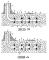
- a horizontal well comprised of a well bore 10 having a conduit 12 disposed therein is schematically illustrated.
- the well bore 10 is positioned substantially vertically until it reaches a subterranean hydrocarbon producing formation 14 whereupon it turns at an angle of about 90° and extends substantially horizontally a distance in the formation 14.
- substantially horizontally as used herein when referring to the position of portions of a well bore and a conduit disposed therein in a subterranean formation means that such portions are positioned with respect to a vertical line extending there above at an angle in the range of from about 45° to about 135°.
- a hardenable resin composition coated particulate solid material of the type described above which is consolidatable into a hard permeable mass is first placed in the annulus 16 between the sides of the well bore 18 and the conduit 12 as shown in FIGURE 1.
- the consolidatable resin composition coated particulate material is preferably pumped through the conduit 12 as a suspension in an aqueous gelled carrier liquid and then into the annulus 16 whereupon the gelled aqueous carrier liquid reverts to a thin liquid and the consolidatable resin coated particulate material is deposited in the annulus 16.
- the resin composition coated particulate material is caused to consolidate into a hard permeable mass which bonds to the walls 18 of the subterranean formation 14 and to the external surfaces of the conduit 12.
- the resin composition coated particulate material is placed and consolidated in only the substantially horizontal portion of the annulus 16, and the usual primary cementing techniques using a hydraulic cement slurry is utilized for cementing the conduit 12 in the vertical portion of the well bore 10.
- a plurality of perforations 20 are formed in the conduit 12 as shown in FIGURE 2.
- the perforations 20 are spaced along the length of the portion of the conduit 12 which is positioned substantially horizontally whereby the perforations divide the conduit into at least two unperforated sections.
- the perforations 20 divide the conduit 12 into four unperforated conduit sections 22, 24, 26 and 28.
- an aqueous cement slurry is introduced into the permeable consolidated particulate material surrounding the conduit 12 within the annulus 16 by way of the perforations 20 whereby sections of the consolidated particulate material corresponding to the unperforated sections 22, 24, 26 and 28 of the conduit 12 are isolated from each other by portions 30 of the cement slurry. That is, after the cement slurry portions 30 set into hard impermeable masses in the consolidated particulate material, hydrocarbons flowing into the consolidated particulate material from the formation 14 are prevented from flowing between adjacent sections of the consolidated particulate material.
- the portions of the cement slurry 30 are allowed to set within the consolidated particulate material in the annulus 16 whereupon the unperforated sections 22, 24, 26 and 28 of the conduit 12 are perforated.
- perforations 32 are formed in the conduit 12 whereby hydrocarbons from the portions of the formation 14 adjacent the conduit sections 22, 24, 26 and 28 flow into the conduit 12 by way of the perforations 32.
- the isolated sections of the consolidated particulate material surrounding the conduit 12 allow tests and treatments to be carried out in selected portions of the formation 14 penetrated by the well bore 10.
- the perforations 32 can be formed separately in the conduit sections 22, 24, 26 and 28, and the hydrocarbon production from the portions of the formation adjacent each section determined. If one or more of the formation sections require stimulation, treatments can be effected in those sections without appreciably disturbing other formation sections.
- the perforations 32 are formed in the conduit 12 whereby the permeable consolidated particulate material surrounding the conduit 12 is disturbed as little as possible. This can be accomplished by utilizing shallow penetration perforation techniques known to those skilled in the art or predrilled perforations with removable plugs therein can be used.
Landscapes
- Life Sciences & Earth Sciences (AREA)
- Engineering & Computer Science (AREA)
- Geology (AREA)
- Mining & Mineral Resources (AREA)
- Physics & Mathematics (AREA)
- Environmental & Geological Engineering (AREA)
- Fluid Mechanics (AREA)
- General Life Sciences & Earth Sciences (AREA)
- Geochemistry & Mineralogy (AREA)
- Aftertreatments Of Artificial And Natural Stones (AREA)
- Compositions Of Macromolecular Compounds (AREA)
Abstract
A well bore (10) having a conduit (12) disposed therein where portions of the well bore and conduit are positioned substantially horizontally in a subterranean producing formation (14), is completed by placing a hardenable resin composition coated particulate solid material in the annulus between the sides of the well bore (10) and the conduit (12) and causing the resin composition to harden whereby the particulate material is consolidated into a hard permeable mass. An aqueous cement slurry (30) is introduced into the permeable consolidated particulate material whereby horizontal sections thereof are isolated which allows tests and/or treatments in selected portions of the horizontal well to be performed.
Description
- The present invention relates to a method of completing portions of a well bore and conduit which are positioned substantially horizontally in a hydrocarbon containing subterranean formation.
- Horizontal wells are those well wherein at least the lower end portion of the well bore is positioned substantially horizontally in a hydrocarbon containing subterranean formation. The horizontal portions of such wells have been completed "open hole" when the material forming the subterranean formation permits and "cased hole" where the subterranean formation is partially or wholly incompetent. In heretofore cased hole completions, the casing has been cemented in the substantially horizontal portion of the well bore utilizing impermeable cement. In those completions, a large number of perforations are generally required in order to allow the hydrocarbons from the subterranean formation to readily flow through the impermeable cement and into the interior of the casing. Also, as a result of the large number of perforations, the migration of incompetent formation materials, e.g. sand, with the hydrocarbons by way of the perforations is often a problem.
- We have now devised an improved horizontal well cased hole completion method whereby high fluid conductivity without sand migration can be achieved.
- According to the present invention, there is provided a method of completing a well bore having a conduit disposed therein where at least the lower end portions of the well bore and conduit are positioned substantially horizontally in a subterranean formation, which method comprises the steps of:
- (a) placing hardenable resin composition coated particulate solid material, which is consolidatable into a hard permeable mass, in the annulus between the sides of said substantially horizontally positioned portions of said well bore and said conduit;
- (b) causing said hardenable resin composition to harden whereby said particulate material is consolidated into a hard permeable mass;
- (c) forming perforations in said substantially horizontally positioned portion of said conduit which divide said conduit into two or more unperforated sections;
- (d) introducing an aqueous cement slurry by way of said perforations into said permeable consolidated particulate material whereby sections thereof corresponding to said unperforated sections of said conduit are isolated from each other by portions of said cement slurry;
- (e) allowing said portions of said cement slurry to set into hard impermeable masses in said consolidated particulate material; and
- (f) perforating one or more of said unperforated sections of said conduit.
- In accordance with the present invention, at least the portions of a well bore and a conduit disposed therein, e.g. casing, which are positioned substantially horizontally in a producing formation are completed by first placing a hardenable resin composition coated particulate solid material in the annulus between the sides of the well bore and the conduit therein. The hardenable resin composition on the particulate material is then caused to harden which consolidates the particulate material into a hard permeable mass. Perforations are next formed in the conduit which are spaced along the horizontal length thereof and divide the conduit into two or more unperforated sections. An aqueous cement slurry is then introduced by way of the perforations into the permeable consolidated particulate material surrounding the conduit whereby sections thereof corresponding to the unperforated sections of the conduit are isolated from each other by portions of the cement slurry. The cement slurry is allowed to set into hard impermeable masses in the consolidated particulate material, and one or more of the unperforated sections of the conduit are perforated to allow the flow of hydrocarbons through the permeable consolidated particulate material into the interior of the conduit. The isolated sections of the permeable consolidated particulate material allow tests and treatments to be performed in selected portions of the producing formation along the length of the substantially horizontal well bore therein.
- In order that the invention may be more fully understood, reference is made to the accompanying drawings, wherein:
- Figure 1 is a schematic illustration of one embodiment of a well bore having a conduit disposed therein positioned substantially horizontally in a subterranean hydrocarbon containing formation, after hardenable resin composition coated particulate solid material has been placed and consolidated between the sides of the well bore and the conduit, in accordance with the invention.
- Figure 2 is a schematic illustration of the well bore and conduit of Figure 1 after perforations dividing the conduit into unperforated sections have been formed therein.
- Figure 3 is a schematic illustration of the well bore and conduit of Figure 2 after an aqueous cement slurry has been introduced by way of the perforations into the permeable consolidated particulate material surrounding the conduit whereby sections thereof corresponding to the unperforated sections of the conduit are isolated from each other.
- Figure 4 is a schematic illustration of the well bore and conduit of Figure 3 after perforations have been formed in each of the conduit sections and hydrocarbon production has been commenced.
- The present invention provides an improved method of completing cased hole horizontal wells. In accordance with the method, a well bore having a conduit disposed therein, e.g. casing, is completed whereby the portions of the well bore and conduit which are positioned substantially horizontally in a hydrocarbon producing formation are bonded together by a consolidated particulate solid material which is permeable to the flow of hydrocarbons. That is, the consolidated particulate solid material has a hydrocarbon fluid conductivity which approaches the fluid conductivity of the hydrocarbon producing formation. In addition, the permeable consolidated particulate solid material provides a barrier between perforations in the conduit and the face of the hydrocarbon producing formation which prevents the migration of sand and other incompetent materials from the formation into the conduit. Also, cement seals are provided in the permeable consolidated particulate material surrounding the conduit which are spaced along the length thereof whereby the consolidated particulate material is divided into isolated horizontal sections. The isolated sections can be separately perforated so that tests and/or treatments can be performed in selected portions of the formation through which the horizontal well bore extends.
- The methods of completing a horizontal well bore as described above comprise the first step of placing a particulate solid material coated with a hardenable resin composition in the annulus between the sides of the substantially horizontal portion of the well bore and the conduit disposed therein. Once placed, the hardenable resin composition is caused to harden which consolidates the particulate material into a hard permeable mass and bonds the conduit to the well bore. A plurality of perforations are next formed in the portion of the conduit surrounded by the consolidated particulate material which are spaced along the length thereof whereby the perforations divide the conduit into two or more unperforated sections. An aqueous slurry of particulate cement having a high degree of fineness is then introduced into the permeable consolidated particulate material by way of the perforations whereby sections thereof corresponding to the unperforated sections of the conduit are isolated from each other by portions of the cement slurry. The cement slurry is allowed to set into hard impermeable masses in the consolidated particulate material. Finally, one or more of the isolated unperforated horizontal sections of the conduit are perforated in a manner whereby the permeable consolidated particulate material surrounding the conduit is left substantially intact and hydrocarbons without incompetent formation materials flow through the perforations into the conduit. As mentioned, since the permeable consolidated particulate material surrounding the conduit is sealed by the set portions of cement between the conduit sections, hydrocarbons from the subterranean formation adjacent one section can not flow by way of the permeable consolidated particulate material to the vicinities of the other sections. This allows the portion of the subterranean formation adjacent each isolated consolidated particulate material and conduit section to be tested or treated independently.
- The hardenable resin composition coated particulate solid material utilized in accordance with this invention can be any of various types of particulate material coated with any of various hardenable resin compositions. The particulate material can be, for example, sand, sintered bauxite, glass particles, and the like. The preferred particulate material is sand having a particle size in the range of from about 10 to about 70 mesh, U.S. Sieve Series (apertures 2.00 to 0.210 mm). The preferred particulate material size ranges are 10-20 mesh (aperture 2.00 to 0.81 mm), 20-40 mesh (aperture 0.81 to 0.42 mm), 40-60 mesh (aperture 0.42 to 0.25 mm) or 50-70 mesh (aperture 0.297 to 0.210 mm) depending upon the particle size and distribution of formation sand adjacent to which the resin coated sand is to be deposited. A preferred hardenable resin composition for coating the particulate material is comprised of a hardenable polyepoxide resin, at least one water immiscible diluent for the resin and a delayed hardening agent for the resin. Polyepoxide resins which can be utilized include the condensation products of epichlorohydrin and multiple hydroxy compounds such as resorcinol hydroquinone, glycerine, pentaerythritol, 1,4-butanediol, phloroglucinol, bisphenol A and bisphenol F. A particularly suitable and preferred such resin is the condensation resin product of epichlorohydrin and bisphenol A. A commercially available such product is marketed by the Shell Chemical Company of Houston, Texas under the tradename EPON 828™. EPON 828™ resin exhibits good temperature stability and chemical resistance, and has a viscosity of about 15,000 centipoises (15 Pas).
- The one or more substantially water immiscible diluents are utilized in the resin composition to adjust the viscosity of the composition to a desired level, generally a level in the range of from about 100 centipoises to about 800 centipoises (0.1 to 0.8 Pas). Preferably two polar organic diluents are used which are miscible with the polyepoxide resin and substantially immiscible with water. One of such diluents is preferably reactive with the epoxy resin component and the other diluent is preferably non-reactive.
- The substantially water immiscible reactive diluent is preferably comprised of at least one member selected from the group consisting of butyl glycidyl ether, cresol glycidyl ether, allyl glycidyl ether, phenyl glycidyl ether, and other glycidyl ethers which are miscible with the epoxy resin utilized. Of these, butyl glycidyl ether and cresol glycidyl ether are the most preferred. The reactive diluent or diluents are generally present in the resin composition in an amount in the range of from about 2 to about 35 parts by weight per 100 parts by weight of the polyepoxy resin present. Preferably, the reactive diluent is present in the range of from about 15 to about 30, and most preferably, about 28 parts by weight per 100 parts by weight of polyepoxide resin.
- Of the various water immiscible non-reactive diluents which can be utilized, one or more selected from the group of ethyl acetate, butyl lactate, ethyl lactate, amyl acetate, ethylene glycol diacetate and propylene glycol diacetate are preferred. Of these, butyl lactate is the most preferred. The water immiscible non-reactive diluent is generally included in the resin composition in an amount in the range of from about 4 to about 20 parts by weight per 100 parts by weight of the polyepoxide resin present. Preferably the non-reactive diluent is present in an amount in the range of from about 8 to about 15, and most preferably about 10 parts by weight per 100 parts by weight of the polyepoxide resin present. Examples of other diluents which can be utilized are methyl alcohol and other low molecular weight alkanols, tetrahydrofurfuryl methacrylate and ethyl acetate.
- A variety of delayed hardening agents can be used in the resin composition. Examples of such hardening agents include amines, polyamines, amides and polyamides. A hardening agent which has been commonly utilized heretofore is methylene dianiline either dissolved in a suitable solvent such as ethyl acetate or in a liquid eutectic mixture of amines diluted with methyl alcohol. A preferred hardening agent is comprised of the adduct formed by reacting an aliphatic or cycloaliphatic amine with the condensation reaction product of epichlorohydrin and bisphenol A. While a variety of aliphatic amines can be utilized, preferred amines are those selected from the group consisting of ethylene diamine, triethylene tetramine, tetraethylene pentamine, bis-(p-aminocyclohexyl) methane, the diamines and triamines of cyclopentane and the diamines and triamines of cyclohexane. Of these, triethylene tetramine, 1,2-diaminocyclohexane and 1,4-diaminocyclohexane are preferred with 1,4-diaminocyclohexane being the most preferred. The adducts of the aliphatic amines are prepared by reacting a selected amine with the condensation reaction product of epichlorohydrin and bisphenol A.
- The preferred hardening agent, i.e., the adduct formed by reacting an aliphatic amine with the condensation reaction product of epichlorohydrin and bisphenol A, is generally included in the resin composition in an amount in the range of from about 20 to about 150 parts by weight per 100 parts by weight of polyepoxy resin. Preferably, the hardening agent is present in an amount in the range of from about 40 to about 90, and most preferably, about 68 parts by weight per 100 parts of polyepoxide resin.
- The hardenable resin composition can also include retarders or accelerators as hardening rate controllers to lengthen or shorten the working and cure times of the resin composition. Low molecular weight organic acid ester retarders such as alkyl esters of alkyl acids containing about 2 to 3 carbon atoms can be utilized. Suitable accelerators include 2,4,6-trisdimethylaminomethylphenol, the ethyl hexonate salt thereof and weak organic acid such as fumaric, erythorbic, ascorbic, salicylic and maleic acids. When a retarder or accelerator is utilized, it is generally combined with the resin composition in amounts up to about 10 parts by weight per 100 parts by weight of polyepoxide resin.
- The resin composition also preferably includes a resin to particulate material coupling agent to promote bonding of the resin to the particulate material. A preferred such coupling agent is N-beta-(aminoethyl)-gamma-aminopropyltrimethoxysilane. The coupling agent generally can be included in the resin composition in an amount from about 0.1 to about 2 parts by weight per 100 parts by weight of polyepoxide resin.
- The preparation of the hardenable resin composition coated particulate solid material and its placement in the well bore, i.e., in the annulus between the sides of the portion of the well bore which is positioned substantially horizontally and the conduit disposed therein, can be accomplished in various ways. For example, the resin coated particulate material can be prepared in a batch mixing operation followed by the suspension of the resin composition coated particulate material in a carrier liquid. The carrier liquid suspension of the resin coated particulate material can then be pumped within the conduit disposed in the well bore through the open end thereof and into the horizontal portion of the annulus between the well bore and the conduit. A more preferred technique for preparing and placing the resin composition coated particulate material is described in United States Patent No. 4,829,100 issued May 9, 1989. In accordance with the technique disclosed therein, a consolidatable resin composition coated particulate material is continuously formed and suspended in a gelled aqueous carrier liquid, and the suspension is pumped to the zone where the resin coated particulate material is to be placed. As described in detail in the patent, substantially continuous streams of a gelled aqueous carrier liquid, uncoated particulate material, a resin composition which will subsequently harden and a surface active agent are admixed whereby the particulate material is continuously coated with resin composition and suspended in the gelled aqueous carrier liquid. The suspension is continuously pumped into the subterranean formation or other zone wherein the consolidatable resin composition coated particulate material is to be deposited.
- The suspension of the hardenable resin composition coated particulate material in an aqueous gelled carrier liquid produced in accordance with Patent No. 4,829,100 is comprised of an aqueous liquid, at least one hydratable polysaccharide gelling agent, the above described resin composition, particulate material and one or more surface active agents for promoting the coating of the particulate material with the resin composition. The aqueous liquid can be fresh water, brine or sea water. A variety of hydratable polysaccharide gelling agents can be utilized having molecular weights in the range of from about 100,000 to 4,000,000, preferably from about 600,000 to 2,400,000. Preferably, the polysaccharide gelling agents are cellulose or guar derivatives. The polymers include substituents such as hydroxyethyl to give the necessary water hydration and gel characteristics to produce a clear aqueous gel having a viscosity of at least about 30 centipoises (0.03 Pas) (reading on a Fann V.G. meter at 300 rpm). Preferred such polymers include substituted carboxy and hydroxy alkyl cellulose, such as hydroxyethylcellulose and carboxymethylhydroxyethylcellulose, and substituted hydroxyalkylguar, such as hydroxypropylguar. The most preferred polysaccharide polymer gelling agent is hydroxypropylguar having a molecular weight in the range of from about 100,000 to about 4,000,000, and having a propylene oxide substitution (MS) of about 0.1 to about 0.7 moles of propylene oxide per mole of mannose and galactose in the guar.
- The surface active agent for promoting the coating of the particulate material can be one or more cationic surface active agents or one or more non-cationic surface active agents, or one or more of both. As used herein, a non-cationic surface active agent includes a blend of anionic and non-ionic surface active agents. Useful cationic surface active agents include the reaction product of an alcohol, epichlorohydrin and triethylenediamine wherein monohydric aliphatic alcohols having in the range of from about 12 to about 18 carbon atoms are reacted with from 2 to 3 moles of epichlorohydrin per mole of alcohol followed by reaction with an excess of triethylenediamine. The alcohol-epichlorohydrin reaction product contains an ethoxylation chain having pendent chlorides. The subsequent reaction with triethylenediamine provides a cationic and a tertiary amine functionality to the resulting product.
- The non-cationic surfactants are preferably ethoxylated fatty acids produced by reacting fatty acids containing from about 12 to about 22 carbon atoms with from about 5 to about 20 moles of ethylene oxide per mole of acid, most preferably from about 12 to about 18 moles of ethylene oxide per mole of acid, to produce a mixture of various quantities of ethoxylated acids and unreacted acids.
- When the gelling agent used is a cellulose derivative, one preferred surface active agent is a blend comprised of isopropyl alcohol, the cationic agent described above and the non-cationic agent described above wherein the weight ratio of cationic agent to non-cationic agent in the blend is in the range of from about 0.4 to 1, and preferably about 0.6 parts by weight cationic agent per 1 part by weight non-cationic agent and wherein the weight ratio of isopropyl alcohol to non-cationic agent in the blend is about 1 part by weight alcohol per 1 part by weight non-cationic agent.
- When the gelling agent used herein is a galactomannan gum, a preferred surface active agent is a blend comprised of alcohol, e.g., amyl alcohol, the cationic agent described above and the non-cationic agent described above wherein the weight ratio of cationic agent to non-cationic agent in the blend is in the range of 0 to 1, and preferably about 0.2 parts by weight cationic agent per 1 part by weight non-cationic agent and wherein the weight ratio of alcohol to non-cationic agent in the blend is about 1 part by weight alcohol per 1 part by weight non-cationic agent.
- After being prepared, the above-described composition is comprised of resin composition coated particulate material suspended in a gelled aqueous liquid. The gelled aqueous liquid preferably contains the polysaccharide polymer utilized in an amount in the range of from about 20 to about 120 lbs (9.1 to 54.5kg) of polymer per 1000 gallons (3.78m³) of water, brine or sea water whereby the gelled aqueous liquid has a viscosity in the range of from about 10 centipoises (0.01Pas) to about 400 centipoises (0.4Pas). Most preferably, the gelled aqueous carrier liquid includes from about 30 to about 80 lbs (13.6 to 36.3kg) of gelling agent per 1000 gallons (3.78m³) of water, brine or sea water, and has a viscosity of from about 15 to about 100 centipoises (0.015 to 0.1Pas). As is well understood by those skilled in the art, the gelled aqueous liquid can be crosslinked to increase its viscosity and stability.
- A gel breaker is included in the gelled aqueous liquid to cause it to revert to a relatively thin liquid at the time the resin coated particulate material reaches the location of its placement. While a variety of gel breakers which are well known in the art can be utilized, an oxidative type of breaker such as sodium persulfate is preferred. Such oxidative gel breakers are generally included in the composition in an amount in the range of from about 0.5 pounds (0.23kg) to about 50 pounds (22.7kg) per 1000 gallons (3.78m³) of gelled aqueous carrier liquid, but the particular amount depends on the specific time period required between when the gel breaker is added and when the gel must be broken. Increases in the amount of gel breaker shorten such time period.
- The aqueous cement slurry useful in accordance with the present invention is comprised of water and a fine particulate hydraulic cement which sets into a hard impermeable mass. The water can be fresh water, salt water, seawater or brine. In order for the particulate hydraulic cement to be capable of flowing into the consolidated particulate solid material it must be of a fine particle size. A preferred such fine particle size cement is one consisting of particles of cementitous material having diameters no larger than about 30 microns (3x10⁻⁵m), preferably no larger than about 17 microns (17x10⁻⁶m), and still more preferably no larger than about 11 microns (11x10⁻⁶m). The distribution of the various sized particles within the cementitious material should be such that 90% of the particles have a diameter not greater than about 25 microns (25x10⁻⁶m), preferably about 10 microns (10⁻⁵m), and still more preferably about 7 microns (7x10⁻⁶m), 50% have a diameter not greater than about 10 microns (10⁻⁵m), preferably about 6 microns (6x10⁻⁶m), and still more preferably about 4 microns (4x10⁻⁶m), and 20% of the particles have a diameter not greater than about 5 microns (5x10⁻⁶m), preferably about 3 microns (3x10⁻⁶m) and still more preferably about 2 microns (2x10⁻⁶m).
- The particle size of the hydraulic cement can be indirectly expressed in terms of the surface area per unit weight of a given sample of the cement. This value, sometimes referred to as Blaine Fineness, can be expressed in units of square centimeters per gram (cm²/gram) and is an indication of the ability of a cement to chemically interact with water and other materials. The activity is believed to increase with increased Blaine Fineness. The Blaine Fineness of the hydraulic cement used in accordance with this invention should be no less than about 6000 cm²/gram, preferably greater than about 7000 cm²/gram, more preferably greater than about 10,000 cm²/gram and most preferably greater than about 13,000 cm²/gram.
- Hydraulic cements having the fineness and particle size distribution described above are disclosed in various prior United States patents including U.S. Patent No. 4,761,183 to Clark which discloses slag and mixtures of slag with Portland cement, and U.S. Patent No. 4,160,674 to Sawyer which discloses Portland cement. The hydraulic cements can also include fine pozzolan cement and/or fine silica in addition to the slag and/or Portland cement. The cements which are preferred for use in accordance with this invention are Portland cement and combinations thereof with slag wherein the quantity of Portland cement included in a mixture of Portland cement and slag can be as low as 10%, but is preferably no less than about 40%, more preferably about 60% and still more preferably about 80%. The most preferred cement of the fineness and particle size distribution described above is Portland cement.
- The aqueous cement slurries useful herein can be formulated utilizing ratios of the weight of water per unit weight of the cementitious material described above in the range of from about 0.5 to about 5.0, preferably from about 1.0 to about 1.75 and still more preferably from about 1.0 to about 1.5 parts by weight of water per part of cementitious material.
- The slurry densities of the fine, i.e., small particle size, cements of this invention are lower than cements having usual particle sizes because of the high water ratios required to wet all of the surface area of the fine cement. The compressive strengths however, of the set lower density slurries are satisfactory for the penetration cementing purposes contemplated herein, especially in view of the greater reactivity of the fine cements. The density of the aqueous cement slurry utilizing the fine cement described can range from about 9.4 to about 14.9.
- Referring now to FIGURES 1 through 4 of the drawing, a horizontal well comprised of a well bore 10 having a
conduit 12 disposed therein is schematically illustrated. The well bore 10 is positioned substantially vertically until it reaches a subterraneanhydrocarbon producing formation 14 whereupon it turns at an angle of about 90° and extends substantially horizontally a distance in theformation 14. The term "substantially horizontally" as used herein when referring to the position of portions of a well bore and a conduit disposed therein in a subterranean formation means that such portions are positioned with respect to a vertical line extending there above at an angle in the range of from about 45° to about 135°. - A hardenable resin composition coated particulate solid material of the type described above which is consolidatable into a hard permeable mass is first placed in the
annulus 16 between the sides of the well bore 18 and theconduit 12 as shown in FIGURE 1. As indicated above, the consolidatable resin composition coated particulate material is preferably pumped through theconduit 12 as a suspension in an aqueous gelled carrier liquid and then into theannulus 16 whereupon the gelled aqueous carrier liquid reverts to a thin liquid and the consolidatable resin coated particulate material is deposited in theannulus 16. After placement, the resin composition coated particulate material is caused to consolidate into a hard permeable mass which bonds to thewalls 18 of thesubterranean formation 14 and to the external surfaces of theconduit 12. Generally, the resin composition coated particulate material is placed and consolidated in only the substantially horizontal portion of theannulus 16, and the usual primary cementing techniques using a hydraulic cement slurry is utilized for cementing theconduit 12 in the vertical portion of the well bore 10. - After the resin composition coated particulate material has been placed and consolidated in the substantially
horizontal annulus 16, a plurality ofperforations 20 are formed in theconduit 12 as shown in FIGURE 2. Theperforations 20 are spaced along the length of the portion of theconduit 12 which is positioned substantially horizontally whereby the perforations divide the conduit into at least two unperforated sections. In FIGURE 2 theperforations 20 divide theconduit 12 into fourunperforated conduit sections - In accordance with the next step of the method of the present invention and as shown in FIGURE 3, an aqueous cement slurry is introduced into the permeable consolidated particulate material surrounding the
conduit 12 within theannulus 16 by way of theperforations 20 whereby sections of the consolidated particulate material corresponding to theunperforated sections conduit 12 are isolated from each other byportions 30 of the cement slurry. That is, after thecement slurry portions 30 set into hard impermeable masses in the consolidated particulate material, hydrocarbons flowing into the consolidated particulate material from theformation 14 are prevented from flowing between adjacent sections of the consolidated particulate material. - The portions of the
cement slurry 30 are allowed to set within the consolidated particulate material in theannulus 16 whereupon theunperforated sections conduit 12 are perforated. As shown in FIGURE 4,perforations 32 are formed in theconduit 12 whereby hydrocarbons from the portions of theformation 14 adjacent theconduit sections conduit 12 by way of theperforations 32. As will be understood by those skilled in the art, the isolated sections of the consolidated particulate material surrounding theconduit 12 allow tests and treatments to be carried out in selected portions of theformation 14 penetrated by the well bore 10. For example, theperforations 32 can be formed separately in theconduit sections - The
perforations 32 are formed in theconduit 12 whereby the permeable consolidated particulate material surrounding theconduit 12 is disturbed as little as possible. This can be accomplished by utilizing shallow penetration perforation techniques known to those skilled in the art or predrilled perforations with removable plugs therein can be used.
Claims (10)
- A method of completing a well bore (10) having a conduit (12) disposed therein where at least the lower end portions of the well bore and conduit are positioned substantially horizontally in a subterranean formation, which method comprises the steps of:(a) placing hardenable resin composition coated particulate solid material, which is consolidatable into a hard permeable mass, in the annulus (16) between the sides (18) of said substantially horizontally positioned portions of said well bore and said conduit (12);(b) causing said hardenable resin composition to harden whereby said particulate material is consolidated into a hard permeable mass;(c) forming perforations (20) in said substantially horizontally positioned portion of said conduit which divide said conduit into two or more unperforated sections (22,24,26,28);(d) introducing an aqueous cement slurry by way of said perforations (20) into said permeable consolidated particulate material whereby sections thereof corresponding to said unperforated sections of said conduit are isolated from each other by portions (30) of said cement slurry;(e) allowing said portions of said cement slurry to set into hard impermeable masses in said consolidated particulate material; and(f) perforating one or more of said unperforated sections of said conduit.
- A method according to claim 1, wherein said resin composition comprises a hardenable polyepoxide resin, a water immiscible diluent for said resin and a hardening agent for said resin.
- A method according to claim 2, wherein said polyepoxide resin is the condensation product of epichlorohydrin and bisphenol A.
- A method according to claim 2 or 3, wherein said hardening agent is the adduct formed by reacting an aliphatic amine with the condensation reaction product of epichlorohydrin and bisphenol A.
- A method according to claim 2, 3 or 4, wherein said diluent is a mixture of a reactive diluent and a non-reactive diluent.
- A method according to claim 5, wherein the reactive diluent is butyl glycidyl ether, cresol glycidyl ether, allyl glycidyl ether or phenyl glycidyl ether.
- A method according to claim 5 or 6, wherein the non-reactive diluent is ethyl acetate, butyl lactate, ethyl lactate, amyl acetate, ethylene glycol diacetate or propylene glycol diacetate.
- A method according to any of claims 1 to 7, wherein said hardenable resin composition coated particulate material is placed in said annulus by suspending it in an aqueous carrier liquid and pumping the resulting suspension into said annulus.
- A method according to any of claims 1 to 8, wherein said aqueous cement slurry comprises water and a hydraulic cement comprised of Portland cement, slag or a mixture thereof having a particle size no greater than 30 microns (3x10⁻⁵m) and a Blaine Fineness of no less than 6000 cm²/gm.
- A method according to claim 9, wherein said cement is Portland cement and wherein 90% of the cement particles have a diameter no greater than 25 microns (25x10⁻⁶m), 50% of the particles have a diameter no greater than 10 microns (10⁻⁵m) and 20% of the particles have a diameter no greater than 5 microns (5x10⁻⁶m).
Applications Claiming Priority (2)
| Application Number | Priority Date | Filing Date | Title |
|---|---|---|---|
| US828076 | 1992-01-30 | ||
| US07/828,076 US5211234A (en) | 1992-01-30 | 1992-01-30 | Horizontal well completion methods |
Publications (1)
| Publication Number | Publication Date |
|---|---|
| EP0553566A1 true EP0553566A1 (en) | 1993-08-04 |
Family
ID=25250873
Family Applications (1)
| Application Number | Title | Priority Date | Filing Date |
|---|---|---|---|
| EP92311746A Ceased EP0553566A1 (en) | 1992-01-30 | 1992-12-23 | Horizontal well completion method |
Country Status (4)
| Country | Link |
|---|---|
| US (1) | US5211234A (en) |
| EP (1) | EP0553566A1 (en) |
| AU (1) | AU653657B2 (en) |
| CA (1) | CA2088292A1 (en) |
Cited By (31)
| Publication number | Priority date | Publication date | Assignee | Title |
|---|---|---|---|---|
| EP0899416A1 (en) * | 1997-08-18 | 1999-03-03 | Halliburton Energy Services, Inc. | Method of sealing conduits in lateral well bores |
| US5957204A (en) * | 1997-08-18 | 1999-09-28 | Halliburton Energy Services, Inc. | Method of sealing conduits in lateral well bores |
| US6006835A (en) * | 1998-02-17 | 1999-12-28 | Halliburton Energy Services, Inc. | Methods for sealing subterranean zones using foamed resin |
| US6006836A (en) * | 1997-08-18 | 1999-12-28 | Halliburton Energy Services, Inc. | Methods of sealing plugs in well bores |
| US6012524A (en) * | 1998-04-14 | 2000-01-11 | Halliburton Energy Services, Inc. | Remedial well bore sealing methods and compositions |
| US6059035A (en) * | 1998-07-20 | 2000-05-09 | Halliburton Energy Services, Inc. | Subterranean zone sealing methods and compositions |
| US6098711A (en) * | 1998-08-18 | 2000-08-08 | Halliburton Energy Services, Inc. | Compositions and methods for sealing pipe in well bores |
| US6124246A (en) * | 1997-11-17 | 2000-09-26 | Halliburton Energy Services, Inc. | High temperature epoxy resin compositions, additives and methods |
| US6231664B1 (en) | 1998-06-30 | 2001-05-15 | Halliburton Energy Services, Inc. | Well sealing compositions and methods |
| US6234251B1 (en) | 1999-02-22 | 2001-05-22 | Halliburton Energy Services, Inc. | Resilient well cement compositions and methods |
| US6244344B1 (en) | 1999-02-09 | 2001-06-12 | Halliburton Energy Services, Inc. | Methods and compositions for cementing pipe strings in well bores |
| US6271181B1 (en) | 1999-02-04 | 2001-08-07 | Halliburton Energy Services, Inc. | Sealing subterranean zones |
| US6279652B1 (en) | 1998-09-23 | 2001-08-28 | Halliburton Energy Services, Inc. | Heat insulation compositions and methods |
| US6401817B1 (en) | 1999-02-04 | 2002-06-11 | Halliburton Energy Services, Inc. | Sealing subterranean zones |
| US6631769B2 (en) | 1999-02-26 | 2003-10-14 | Shell Oil Company | Method of operating an apparatus for radially expanding a tubular member |
| US6634431B2 (en) | 1998-11-16 | 2003-10-21 | Robert Lance Cook | Isolation of subterranean zones |
| US6712154B2 (en) | 1998-11-16 | 2004-03-30 | Enventure Global Technology | Isolation of subterranean zones |
| US6739392B2 (en) | 1998-12-07 | 2004-05-25 | Shell Oil Company | Forming a wellbore casing while simultaneously drilling a wellbore |
| US6745845B2 (en) | 1998-11-16 | 2004-06-08 | Shell Oil Company | Isolation of subterranean zones |
| US6823937B1 (en) | 1998-12-07 | 2004-11-30 | Shell Oil Company | Wellhead |
| US7100685B2 (en) * | 2000-10-02 | 2006-09-05 | Enventure Global Technology | Mono-diameter wellbore casing |
| US7546881B2 (en) | 2001-09-07 | 2009-06-16 | Enventure Global Technology, Llc | Apparatus for radially expanding and plastically deforming a tubular member |
| US7665532B2 (en) | 1998-12-07 | 2010-02-23 | Shell Oil Company | Pipeline |
| US7712522B2 (en) | 2003-09-05 | 2010-05-11 | Enventure Global Technology, Llc | Expansion cone and system |
| US7739917B2 (en) | 2002-09-20 | 2010-06-22 | Enventure Global Technology, Llc | Pipe formability evaluation for expandable tubulars |
| US7740076B2 (en) | 2002-04-12 | 2010-06-22 | Enventure Global Technology, L.L.C. | Protective sleeve for threaded connections for expandable liner hanger |
| US7775290B2 (en) | 2003-04-17 | 2010-08-17 | Enventure Global Technology, Llc | Apparatus for radially expanding and plastically deforming a tubular member |
| US7793721B2 (en) | 2003-03-11 | 2010-09-14 | Eventure Global Technology, Llc | Apparatus for radially expanding and plastically deforming a tubular member |
| US7819185B2 (en) | 2004-08-13 | 2010-10-26 | Enventure Global Technology, Llc | Expandable tubular |
| US7886831B2 (en) | 2003-01-22 | 2011-02-15 | Enventure Global Technology, L.L.C. | Apparatus for radially expanding and plastically deforming a tubular member |
| US7918284B2 (en) | 2002-04-15 | 2011-04-05 | Enventure Global Technology, L.L.C. | Protective sleeve for threaded connections for expandable liner hanger |
Families Citing this family (46)
| Publication number | Priority date | Publication date | Assignee | Title |
|---|---|---|---|---|
| US5332037A (en) * | 1992-11-16 | 1994-07-26 | Atlantic Richfield Company | Squeeze cementing method for wells |
| US5346012A (en) * | 1993-02-01 | 1994-09-13 | Halliburton Company | Fine particle size cement compositions and methods |
| US5339902A (en) * | 1993-04-02 | 1994-08-23 | Halliburton Company | Well cementing using permeable cement |
| US5664628A (en) * | 1993-05-25 | 1997-09-09 | Pall Corporation | Filter for subterranean wells |
| GB9313081D0 (en) * | 1993-06-25 | 1993-08-11 | Pumptech Nv | Selective zonal isolation of oil wells |
| US5598890A (en) * | 1995-10-23 | 1997-02-04 | Baker Hughes Inc. | Completion assembly |
| UA67719C2 (en) * | 1995-11-08 | 2004-07-15 | Shell Int Research | Deformable well filter and method for its installation |
| US6311772B1 (en) | 1998-11-03 | 2001-11-06 | Baker Hughes Incorporated | Hydrocarbon preparation system for open hole zonal isolation and control |
| AU2004203176B2 (en) * | 1998-11-03 | 2006-09-28 | Baker Hughes Incorporated | Open hole zonal isolation and control |
| US6318465B1 (en) * | 1998-11-03 | 2001-11-20 | Baker Hughes Incorporated | Unconsolidated zonal isolation and control |
| US6619397B2 (en) | 1998-11-03 | 2003-09-16 | Baker Hughes Incorporated | Unconsolidated zonal isolation and control |
| US6446726B1 (en) | 2000-03-09 | 2002-09-10 | Halliburton Energy Services, Inc. | Wellbore and formation heating system and method |
| US6454006B1 (en) | 2000-03-28 | 2002-09-24 | Halliburton Energy Services, Inc. | Methods and associated apparatus for drilling and completing a wellbore junction |
| US6321841B1 (en) | 2001-02-21 | 2001-11-27 | Halliburton Energy Services, Inc. | Methods of sealing pipe strings in disposal wells |
| US7140438B2 (en) * | 2003-08-14 | 2006-11-28 | Halliburton Energy Services, Inc. | Orthoester compositions and methods of use in subterranean applications |
| US6962200B2 (en) * | 2002-01-08 | 2005-11-08 | Halliburton Energy Services, Inc. | Methods and compositions for consolidating proppant in subterranean fractures |
| US6691780B2 (en) | 2002-04-18 | 2004-02-17 | Halliburton Energy Services, Inc. | Tracking of particulate flowback in subterranean wells |
| US7497278B2 (en) * | 2003-08-14 | 2009-03-03 | Halliburton Energy Services, Inc. | Methods of degrading filter cakes in a subterranean formation |
| US20050173116A1 (en) | 2004-02-10 | 2005-08-11 | Nguyen Philip D. | Resin compositions and methods of using resin compositions to control proppant flow-back |
| US7211547B2 (en) | 2004-03-03 | 2007-05-01 | Halliburton Energy Services, Inc. | Resin compositions and methods of using such resin compositions in subterranean applications |
| US7299875B2 (en) | 2004-06-08 | 2007-11-27 | Halliburton Energy Services, Inc. | Methods for controlling particulate migration |
| US7757768B2 (en) | 2004-10-08 | 2010-07-20 | Halliburton Energy Services, Inc. | Method and composition for enhancing coverage and displacement of treatment fluids into subterranean formations |
| US7883740B2 (en) | 2004-12-12 | 2011-02-08 | Halliburton Energy Services, Inc. | Low-quality particulates and methods of making and using improved low-quality particulates |
| US7673686B2 (en) | 2005-03-29 | 2010-03-09 | Halliburton Energy Services, Inc. | Method of stabilizing unconsolidated formation for sand control |
| US7318474B2 (en) | 2005-07-11 | 2008-01-15 | Halliburton Energy Services, Inc. | Methods and compositions for controlling formation fines and reducing proppant flow-back |
| US8613320B2 (en) | 2006-02-10 | 2013-12-24 | Halliburton Energy Services, Inc. | Compositions and applications of resins in treating subterranean formations |
| US7819192B2 (en) | 2006-02-10 | 2010-10-26 | Halliburton Energy Services, Inc. | Consolidating agent emulsions and associated methods |
| US7926591B2 (en) | 2006-02-10 | 2011-04-19 | Halliburton Energy Services, Inc. | Aqueous-based emulsified consolidating agents suitable for use in drill-in applications |
| US7665517B2 (en) | 2006-02-15 | 2010-02-23 | Halliburton Energy Services, Inc. | Methods of cleaning sand control screens and gravel packs |
| US7678743B2 (en) | 2006-09-20 | 2010-03-16 | Halliburton Energy Services, Inc. | Drill-in fluids and associated methods |
| US7678742B2 (en) | 2006-09-20 | 2010-03-16 | Halliburton Energy Services, Inc. | Drill-in fluids and associated methods |
| US7687438B2 (en) | 2006-09-20 | 2010-03-30 | Halliburton Energy Services, Inc. | Drill-in fluids and associated methods |
| US7934557B2 (en) | 2007-02-15 | 2011-05-03 | Halliburton Energy Services, Inc. | Methods of completing wells for controlling water and particulate production |
| US7762329B1 (en) | 2009-01-27 | 2010-07-27 | Halliburton Energy Services, Inc. | Methods for servicing well bores with hardenable resin compositions |
| US7882894B2 (en) * | 2009-02-20 | 2011-02-08 | Halliburton Energy Services, Inc. | Methods for completing and stimulating a well bore |
| US7998910B2 (en) | 2009-02-24 | 2011-08-16 | Halliburton Energy Services, Inc. | Treatment fluids comprising relative permeability modifiers and methods of use |
| CN101701518B (en) * | 2009-09-15 | 2014-03-12 | 中国海洋石油总公司 | Pipe string used for high-speed test of pressure control and water stabilization of horizontal well |
| US8371370B2 (en) * | 2009-12-09 | 2013-02-12 | Baker Hughes Incorporated | Apparatus for isolating and completing multi-zone frac packs |
| US9233874B2 (en) | 2010-07-21 | 2016-01-12 | Halliburton Energy Services, Inc. | Cement compositions with a high-density additive of silicon carbide or sintered bauxite |
| US9689235B1 (en) | 2014-04-16 | 2017-06-27 | The United States Of America As Represented By The Secretary Of The Department Of The Interior | Safe, directional, drought-resistant dug well (SDDW) |
| US10947438B2 (en) | 2016-09-20 | 2021-03-16 | Saudi Arabian Oil Company | Method for monitoring cement using polymer-based capsules |
| US10619085B2 (en) | 2018-01-02 | 2020-04-14 | Saudi Arabian Oil Company | Method for controlled release and making of a cement additive in a wellbore |
| US10947437B2 (en) | 2016-09-20 | 2021-03-16 | Saudi Arabian Oil Company | Chemical composition of superabsorbent vesicles, method for mortar cement admixture, and applications of the same |
| US10377940B2 (en) | 2016-09-20 | 2019-08-13 | Saudi Arabian Oil Company | Cement having cross-linked polymers |
| CA3087056A1 (en) | 2018-01-02 | 2019-07-11 | Saudi Arabian Oil Company | Composition of encapsulated chemical additives and methods for preparation of the same |
| WO2019135938A1 (en) | 2018-01-02 | 2019-07-11 | Saudi Arabian Oil Company | Capsule design for the capture of reagents |
Citations (2)
| Publication number | Priority date | Publication date | Assignee | Title |
|---|---|---|---|---|
| US3542132A (en) * | 1969-04-21 | 1970-11-24 | Gulf Research Development Co | Method of squeeze cementing a well |
| US4917188A (en) * | 1989-01-09 | 1990-04-17 | Halliburton Company | Method for setting well casing using a resin coated particulate |
Family Cites Families (11)
| Publication number | Priority date | Publication date | Assignee | Title |
|---|---|---|---|---|
| US2248028A (en) * | 1938-06-09 | 1941-07-01 | Dow Chemical Co | Treatment of wells |
| US3708013A (en) * | 1971-05-03 | 1973-01-02 | Mobil Oil Corp | Method and apparatus for obtaining an improved gravel pack |
| US3967681A (en) * | 1975-09-30 | 1976-07-06 | Phillips Petroleum Company | Repair of cement sheath around well casing |
| US4682652A (en) * | 1986-06-30 | 1987-07-28 | Texaco Inc. | Producing hydrocarbons through successively perforated intervals of a horizontal well between two vertical wells |
| US4942186A (en) * | 1987-10-23 | 1990-07-17 | Halliburton Company | Continuously forming and transporting consolidatable resin coated particulate materials in aqueous gels |
| US4829100A (en) * | 1987-10-23 | 1989-05-09 | Halliburton Company | Continuously forming and transporting consolidatable resin coated particulate materials in aqueous gels |
| US5058676A (en) * | 1989-10-30 | 1991-10-22 | Halliburton Company | Method for setting well casing using a resin coated particulate |
| US5103912A (en) * | 1990-08-13 | 1992-04-14 | Flint George R | Method and apparatus for completing deviated and horizontal wellbores |
| US5127473A (en) * | 1991-01-08 | 1992-07-07 | Halliburton Services | Repair of microannuli and cement sheath |
| US5121795A (en) * | 1991-01-08 | 1992-06-16 | Halliburton Company | Squeeze cementing |
| US5095987A (en) * | 1991-01-31 | 1992-03-17 | Halliburton Company | Method of forming and using high density particulate slurries for well completion |
-
1992
- 1992-01-30 US US07/828,076 patent/US5211234A/en not_active Expired - Lifetime
- 1992-12-14 AU AU30112/92A patent/AU653657B2/en not_active Ceased
- 1992-12-23 EP EP92311746A patent/EP0553566A1/en not_active Ceased
-
1993
- 1993-01-28 CA CA002088292A patent/CA2088292A1/en not_active Abandoned
Patent Citations (2)
| Publication number | Priority date | Publication date | Assignee | Title |
|---|---|---|---|---|
| US3542132A (en) * | 1969-04-21 | 1970-11-24 | Gulf Research Development Co | Method of squeeze cementing a well |
| US4917188A (en) * | 1989-01-09 | 1990-04-17 | Halliburton Company | Method for setting well casing using a resin coated particulate |
Cited By (40)
| Publication number | Priority date | Publication date | Assignee | Title |
|---|---|---|---|---|
| US5957204A (en) * | 1997-08-18 | 1999-09-28 | Halliburton Energy Services, Inc. | Method of sealing conduits in lateral well bores |
| US5969006A (en) * | 1997-08-18 | 1999-10-19 | Halliburton Energy Services, Inc. | Remedial well bore sealing methods |
| US6006836A (en) * | 1997-08-18 | 1999-12-28 | Halliburton Energy Services, Inc. | Methods of sealing plugs in well bores |
| EP0899416A1 (en) * | 1997-08-18 | 1999-03-03 | Halliburton Energy Services, Inc. | Method of sealing conduits in lateral well bores |
| US6124246A (en) * | 1997-11-17 | 2000-09-26 | Halliburton Energy Services, Inc. | High temperature epoxy resin compositions, additives and methods |
| US6006835A (en) * | 1998-02-17 | 1999-12-28 | Halliburton Energy Services, Inc. | Methods for sealing subterranean zones using foamed resin |
| US6069117A (en) * | 1998-02-17 | 2000-05-30 | Halliburton Energy Services, Inc. | Foamed resin compositions for sealing subterranean zones |
| US6012524A (en) * | 1998-04-14 | 2000-01-11 | Halliburton Energy Services, Inc. | Remedial well bore sealing methods and compositions |
| US6231664B1 (en) | 1998-06-30 | 2001-05-15 | Halliburton Energy Services, Inc. | Well sealing compositions and methods |
| US6059035A (en) * | 1998-07-20 | 2000-05-09 | Halliburton Energy Services, Inc. | Subterranean zone sealing methods and compositions |
| US6098711A (en) * | 1998-08-18 | 2000-08-08 | Halliburton Energy Services, Inc. | Compositions and methods for sealing pipe in well bores |
| US6279652B1 (en) | 1998-09-23 | 2001-08-28 | Halliburton Energy Services, Inc. | Heat insulation compositions and methods |
| US6745845B2 (en) | 1998-11-16 | 2004-06-08 | Shell Oil Company | Isolation of subterranean zones |
| US6712154B2 (en) | 1998-11-16 | 2004-03-30 | Enventure Global Technology | Isolation of subterranean zones |
| US6634431B2 (en) | 1998-11-16 | 2003-10-21 | Robert Lance Cook | Isolation of subterranean zones |
| US6758278B2 (en) | 1998-12-07 | 2004-07-06 | Shell Oil Company | Forming a wellbore casing while simultaneously drilling a wellbore |
| US6739392B2 (en) | 1998-12-07 | 2004-05-25 | Shell Oil Company | Forming a wellbore casing while simultaneously drilling a wellbore |
| US7665532B2 (en) | 1998-12-07 | 2010-02-23 | Shell Oil Company | Pipeline |
| US6823937B1 (en) | 1998-12-07 | 2004-11-30 | Shell Oil Company | Wellhead |
| US6555507B2 (en) | 1999-02-04 | 2003-04-29 | Halliburton Energy Services, Inc. | Sealing subterranean zones |
| US6448206B1 (en) | 1999-02-04 | 2002-09-10 | Halliburton Energy Services, Inc. | Sealing subterranean zones |
| US6401817B1 (en) | 1999-02-04 | 2002-06-11 | Halliburton Energy Services, Inc. | Sealing subterranean zones |
| US6271181B1 (en) | 1999-02-04 | 2001-08-07 | Halliburton Energy Services, Inc. | Sealing subterranean zones |
| US6350309B2 (en) | 1999-02-09 | 2002-02-26 | Halliburton Energy Services, Inc. | Methods and compositions for cementing pipe strings in well bores |
| US6244344B1 (en) | 1999-02-09 | 2001-06-12 | Halliburton Energy Services, Inc. | Methods and compositions for cementing pipe strings in well bores |
| US6593402B2 (en) | 1999-02-22 | 2003-07-15 | Halliburton Energy Services, Inc. | Resilient well cement compositions and methods |
| US6234251B1 (en) | 1999-02-22 | 2001-05-22 | Halliburton Energy Services, Inc. | Resilient well cement compositions and methods |
| US6631769B2 (en) | 1999-02-26 | 2003-10-14 | Shell Oil Company | Method of operating an apparatus for radially expanding a tubular member |
| US6684947B2 (en) | 1999-02-26 | 2004-02-03 | Shell Oil Company | Apparatus for radially expanding a tubular member |
| US7100685B2 (en) * | 2000-10-02 | 2006-09-05 | Enventure Global Technology | Mono-diameter wellbore casing |
| US7546881B2 (en) | 2001-09-07 | 2009-06-16 | Enventure Global Technology, Llc | Apparatus for radially expanding and plastically deforming a tubular member |
| GB2380503B (en) * | 2001-10-03 | 2005-10-26 | Shell Oil Co | Isolation of subterranean zones |
| US7740076B2 (en) | 2002-04-12 | 2010-06-22 | Enventure Global Technology, L.L.C. | Protective sleeve for threaded connections for expandable liner hanger |
| US7918284B2 (en) | 2002-04-15 | 2011-04-05 | Enventure Global Technology, L.L.C. | Protective sleeve for threaded connections for expandable liner hanger |
| US7739917B2 (en) | 2002-09-20 | 2010-06-22 | Enventure Global Technology, Llc | Pipe formability evaluation for expandable tubulars |
| US7886831B2 (en) | 2003-01-22 | 2011-02-15 | Enventure Global Technology, L.L.C. | Apparatus for radially expanding and plastically deforming a tubular member |
| US7793721B2 (en) | 2003-03-11 | 2010-09-14 | Eventure Global Technology, Llc | Apparatus for radially expanding and plastically deforming a tubular member |
| US7775290B2 (en) | 2003-04-17 | 2010-08-17 | Enventure Global Technology, Llc | Apparatus for radially expanding and plastically deforming a tubular member |
| US7712522B2 (en) | 2003-09-05 | 2010-05-11 | Enventure Global Technology, Llc | Expansion cone and system |
| US7819185B2 (en) | 2004-08-13 | 2010-10-26 | Enventure Global Technology, Llc | Expandable tubular |
Also Published As
| Publication number | Publication date |
|---|---|
| CA2088292A1 (en) | 1993-07-31 |
| US5211234A (en) | 1993-05-18 |
| AU653657B2 (en) | 1994-10-06 |
| AU3011292A (en) | 1993-08-05 |
Similar Documents
| Publication | Publication Date | Title |
|---|---|---|
| US5211234A (en) | Horizontal well completion methods | |
| AU648683B2 (en) | Hardenable resin compositions and methods | |
| EP0313243B1 (en) | Method for providing coated particulate materials suspended in aqueous gels | |
| US5381864A (en) | Well treating methods using particulate blends | |
| US4665988A (en) | Method of preparation of variable permeability fill material for use in subterranean formations | |
| US4942186A (en) | Continuously forming and transporting consolidatable resin coated particulate materials in aqueous gels | |
| EP0497055B1 (en) | High density particulate slurries for well completion | |
| US5321062A (en) | Substituted alkoxy benzene and use thereof as wetting aid for polyepoxide resins | |
| US5791415A (en) | Stimulating wells in unconsolidated formations | |
| US4199484A (en) | Gelled water epoxy sand consolidation system | |
| US6016870A (en) | Compositions and methods for consolidating unconsolidated subterranean zones | |
| CA2250566C (en) | Methods of rapidly consolidating particulate materials in wells | |
| US4216829A (en) | Gelled water epoxy sand consolidation system | |
| US4368136A (en) | Aqueous gel composition for temporary stabilization of subterranean well formation | |
| CA2214169C (en) | Unconsolidated formation stimulation and sand migration prevention methods | |
| US5924488A (en) | Methods of preventing well fracture proppant flow-back | |
| US3854533A (en) | Method for forming a consolidated gravel pack in a subterranean formation | |
| US6705400B1 (en) | Methods and compositions for forming subterranean fractures containing resilient proppant packs | |
| AU2003200033B2 (en) | Methods of consolidating proppant in subterranean fractures | |
| US20080289824A1 (en) | Primary Well Cementing With Downhole Mixed Epoxy | |
| EP0643196A2 (en) | Consolidatable particulate material and well treatment method | |
| AU2003204526A1 (en) | Methods of consolidating proppant and controlling fines in wells | |
| US6155348A (en) | Stimulating unconsolidated producing zones in wells | |
| MXPA03011436A (en) | Permeable cement composition and method for preparing the same. | |
| CN108751915B (en) | Water plugging fracturing tectorial membrane proppant for bottom water reservoir and preparation method |
Legal Events
| Date | Code | Title | Description |
|---|---|---|---|
| PUAI | Public reference made under article 153(3) epc to a published international application that has entered the european phase |
Free format text: ORIGINAL CODE: 0009012 |
|
| AK | Designated contracting states |
Kind code of ref document: A1 Designated state(s): DE DK ES FR GB IT NL |
|
| 17P | Request for examination filed |
Effective date: 19930930 |
|
| 17Q | First examination report despatched |
Effective date: 19950126 |
|
| STAA | Information on the status of an ep patent application or granted ep patent |
Free format text: STATUS: THE APPLICATION HAS BEEN REFUSED |
|
| 18R | Application refused |
Effective date: 19950716 |