EP0553891A2 - Method of producing a suturing needle with suture - Google Patents
Method of producing a suturing needle with suture Download PDFInfo
- Publication number
- EP0553891A2 EP0553891A2 EP93104439A EP93104439A EP0553891A2 EP 0553891 A2 EP0553891 A2 EP 0553891A2 EP 93104439 A EP93104439 A EP 93104439A EP 93104439 A EP93104439 A EP 93104439A EP 0553891 A2 EP0553891 A2 EP 0553891A2
- Authority
- EP
- European Patent Office
- Prior art keywords
- needle
- suture
- tube
- suturing
- producing
- Prior art date
- Legal status (The legal status is an assumption and is not a legal conclusion. Google has not performed a legal analysis and makes no representation as to the accuracy of the status listed.)
- Ceased
Links
Images


Classifications
-
- A—HUMAN NECESSITIES
- A61—MEDICAL OR VETERINARY SCIENCE; HYGIENE
- A61B—DIAGNOSIS; SURGERY; IDENTIFICATION
- A61B17/00—Surgical instruments, devices or methods, e.g. tourniquets
- A61B17/04—Surgical instruments, devices or methods, e.g. tourniquets for suturing wounds; Holders or packages for needles or suture materials
- A61B17/06—Needles ; Sutures; Needle-suture combinations; Holders or packages for needles or suture materials
- A61B17/06066—Needles, e.g. needle tip configurations
-
- A—HUMAN NECESSITIES
- A61—MEDICAL OR VETERINARY SCIENCE; HYGIENE
- A61B—DIAGNOSIS; SURGERY; IDENTIFICATION
- A61B17/00—Surgical instruments, devices or methods, e.g. tourniquets
- A61B17/04—Surgical instruments, devices or methods, e.g. tourniquets for suturing wounds; Holders or packages for needles or suture materials
- A61B17/06—Needles ; Sutures; Needle-suture combinations; Holders or packages for needles or suture materials
- A61B17/06004—Means for attaching suture to needle
- A61B2017/06028—Means for attaching suture to needle by means of a cylindrical longitudinal blind bore machined at the suture-receiving end of the needle, e.g. opposite to needle tip
-
- A—HUMAN NECESSITIES
- A61—MEDICAL OR VETERINARY SCIENCE; HYGIENE
- A61B—DIAGNOSIS; SURGERY; IDENTIFICATION
- A61B17/00—Surgical instruments, devices or methods, e.g. tourniquets
- A61B17/04—Surgical instruments, devices or methods, e.g. tourniquets for suturing wounds; Holders or packages for needles or suture materials
- A61B17/06—Needles ; Sutures; Needle-suture combinations; Holders or packages for needles or suture materials
- A61B2017/06052—Needle-suture combinations in which a suture is extending inside a hollow tubular needle, e.g. over the entire length of the needle
-
- Y—GENERAL TAGGING OF NEW TECHNOLOGICAL DEVELOPMENTS; GENERAL TAGGING OF CROSS-SECTIONAL TECHNOLOGIES SPANNING OVER SEVERAL SECTIONS OF THE IPC; TECHNICAL SUBJECTS COVERED BY FORMER USPC CROSS-REFERENCE ART COLLECTIONS [XRACs] AND DIGESTS
- Y10—TECHNICAL SUBJECTS COVERED BY FORMER USPC
- Y10T—TECHNICAL SUBJECTS COVERED BY FORMER US CLASSIFICATION
- Y10T29/00—Metal working
- Y10T29/49—Method of mechanical manufacture
- Y10T29/49826—Assembling or joining
- Y10T29/49861—Sizing mating parts during final positional association
-
- Y—GENERAL TAGGING OF NEW TECHNOLOGICAL DEVELOPMENTS; GENERAL TAGGING OF CROSS-SECTIONAL TECHNOLOGIES SPANNING OVER SEVERAL SECTIONS OF THE IPC; TECHNICAL SUBJECTS COVERED BY FORMER USPC CROSS-REFERENCE ART COLLECTIONS [XRACs] AND DIGESTS
- Y10—TECHNICAL SUBJECTS COVERED BY FORMER USPC
- Y10T—TECHNICAL SUBJECTS COVERED BY FORMER US CLASSIFICATION
- Y10T29/00—Metal working
- Y10T29/49—Method of mechanical manufacture
- Y10T29/49826—Assembling or joining
- Y10T29/49879—Spaced wall tube or receptacle
-
- Y—GENERAL TAGGING OF NEW TECHNOLOGICAL DEVELOPMENTS; GENERAL TAGGING OF CROSS-SECTIONAL TECHNOLOGIES SPANNING OVER SEVERAL SECTIONS OF THE IPC; TECHNICAL SUBJECTS COVERED BY FORMER USPC CROSS-REFERENCE ART COLLECTIONS [XRACs] AND DIGESTS
- Y10—TECHNICAL SUBJECTS COVERED BY FORMER USPC
- Y10T—TECHNICAL SUBJECTS COVERED BY FORMER US CLASSIFICATION
- Y10T29/00—Metal working
- Y10T29/49—Method of mechanical manufacture
- Y10T29/49826—Assembling or joining
- Y10T29/49908—Joining by deforming
- Y10T29/49925—Inward deformation of aperture or hollow body wall
- Y10T29/49927—Hollow body is axially joined cup or tube
- Y10T29/49929—Joined to rod
Definitions
- the present invention relates to a suturing needle with suture used in a surgical operation and a method of producing the same. More specifically, it relates to the suturing needle with suture formed of a hollow tube and a core material inserted thereinto and its production method.
- the inner core material inserted into the suturing needle is fixed to its tip and root to prevent broken pieces from scattering when the needle is broken to pieces from a body tissue.
- Two types of surgical suturing needle are known when classified roughly. One is an eyed type and the other is an eyeless type.
- suturing needle As the eyed type suturing needle, the one disclosed, for example, in Japanese Utility Model Publication No. Sho 46-12549 (12549/1971) is well known.
- a threading hole is provided at the end on its root side.
- a suture is adapted to be inserted through the threading hole of the needle at operation.
- the eyeless type suturing needle the one disclosed, for example, in Japanese Patent Publication No. Sho 59-15648 (15648/1984) is well known.
- this type of suturing needle the suture is bound integrally with the suturing needle beforehand at production.
- a prepared hole having a diameter smaller than the suture is opened on the end surface of the needle root.
- the prepared hole is expanded into a binding hole having the same or larger diameter than the suture.
- the suture is inserted into the binding hole to be bound integrally with the suturing needle by caulking.
- a groove for the suture is provided generally throughout the whole length of the suturing needle.
- the portion of suture inserted into the groove is fixed to the suturing needle by caulking and formed as the suturing needle with suture.
- this type of suturing needle is made of a plate material and thus grinding of its tip, lip or the like is insufficient. Therefore, the sharpness (smooth penetration into the tissue) of the needle is deteriorated and becomes impractical.
- the suturing needle with suture is formed of a hollow tube and an inner core material, one end of which is fixed to the needle point so as not to be exposed from the needle and the other end is fixed to the needle before a suture fixing hole provided at the rear end thereof, to which the tip of the suture is fixed.
- the suturing needle with suture according to the present invention is produced in such a manner that one end of the hollow tube of a unit length inserted with the inner core material is tapered off to form the needle point holding one end of said inner core material as a needle body, which is cut into the length of the suturing needle and at the same time, the other end of the needle body on the opposite side of the needle point is formed with the suture fixing hole and processed to fix the other end of the inner core material and to form the suturing needle.
- the suturing needle fixed with the inner core material is curved in a prescribed shape and the tip of the suture is fixed to the suture fixing hole of the needle.
- FIG. 1 through Fig. 9 of the accompanying drawings show one embodiment of the present invention, wherein a most popular case of a so-called round needle formed of a suturing needle curved in a circular arc is shown.
- the suturing needle 1 is formed of a single hollow tube 1a and a flexible inner core material 6 inserted into a hollow slit or interior 4 thereof.
- the inner core material 6 is fixed to a point of the needle 1 at its one end and the other end is fixed with a caulking or sealing portion 5 at a root 3 of the needle 1.
- the point 2 of the suturing needle 1 is formed by welding one end of the hollow tube 1a and one end of the inner core material 6 inserted into the hollow slit 4, fixing by means of pressing or by any other fixing means and swaging the tip portion of the fixed hollow tube 1a and the inner core material 6.
- one end of a suture 7 is fixed integrally in abutment with the inner core material 6 by means of caulking pressing, swaging, or by any other fixing means.
- a sectional shape of the needle 1 is formed such that, for example, generally one third of the total length (needle point) on the needle point side makes a triangle, succeeding portion in the length of about one third (middle) makes a circle and the remaining one third (rear end of the needle) makes an oval.
- the needle point 2 is formed with a point angle ⁇ of a prescribed size at its tip, and an apex of the triangular section at the needle point is formed with a cutter blade.
- a circular shape is more suitable than a square as the sectional shape of the needle point.
- the hollow tube which is a material for the needle win this case, stainless steel in the group of SUS 304 of the Japanese Industrial Standard (JIS) is utilized.
- JIS Japanese Industrial Standard
- the suture 7 may be fixed, as shown in Fig. 14, by expanding the hollow slit 4 to form a suture fixing hole 9 and to adhere the contact surface with the inner core material 6 by means of an adhesive 10, or as shown in Fig. 15, by forming a notched face 11 partly on the side of the suture 7 to overlap the inner core material 6 thereon for caulking, pressing or swaging, or by using the adhesive 10 together.
- the production procedures mentioned heretofore may be employed also in the hollow tube made of a stainless material such as stainless steel in SUS 301 group or titanium besides stainless steel in SUS 304 group as the material of the suturing needle 1.
- a stainless material such as stainless steel in SUS 301 group or titanium besides stainless steel in SUS 304 group
- the material such as silicoroy having a sufficient hardness
- heat treatment and electrolytic grinding processes among the above production procedures may be omitted.
- the suturing needle 1 is formed with the hollow tube 1a, and at production, a prepared hole for fixing the suture 7 does not require to be opened at the rear end of the needle 1 or further to be expanded, fixing of the suture 7 is considerably simplified.
- the needle 1 is not only strengthened by the inner core material 6, but even if the needle 1 is broken for any reason during operation, by pulling a portion of the needle 1 remaining outside the tissue, broken pieces linked together with the inner core material 6 can be easily extracted.
- the needle point 2 of the needle 1 is annealed when welding one end of the hollow tube 1a, so that it can be easily formed by tip swaging. Besides, the surface hardness of the needle point 2 thus formed is not increased so excessively as to lose its tenacity, and thus the resistance force against shock is strengthened.
- the inner core material 6 can be inserted into the hollow tube 4 of the needle 1 without disposing a groove generally throughout the total length thereof. Therefore, the needle surface is free from any flow caused by the groove and grinding of the nose and cutting edge is performed sufficiently, and thus a sharp suturing needle 1 having a smooth surface can be provided.
- Fig. 11 and Fig. 12 show another embodiment of the present invention, wherein an inner core material 6A is inserted into a hollow slit or interior 4A formed inside a double hollow tube 1A, 1B doubled via a slight gap, and its rear end and a suture 7A are respectively fixed with a caulking or fixing portion 5A and 8A of the double hollow tube 1A, 1B.
- the material cost can be reduced compared with a single tube needle having the same thickness.
- Fig. 13 shows still another embodiment of the present invention, wherein an inner core material 6B is inserted into a hollow slit or interior 4B formed inside the hollow tubes 1A, 1C having a different length and doubled via a slight gap, and its rear end is fixed with a caulking or fixing portion 5B of the hollow tubes 1A, 1C and a suture 7B is fixed with a caulking or fixing portion 8B of the outer hollow tube 1A slightly longer than the inner hollow tube 1C.
- the diameter of the suture 7B fixed to the needle 1 can be enlarged to decrease a difference with the outside diameter of the needle 1.
- the strength of the suture 7B fixed to the needle 1 having the same size can be strengthened at suturing.
- Fig. 16 and Fig. 17 show another different embodiment of the present invention, wherein a suture cutter 12, 13 is disposed on the needle 1 of each embodiment aforementioned.
- the suture cutter 12 is formed circularly at the edge of the needle root 3 of the needle 1 in a right angle to the lengthwise direction, while in Fig. 17, the suture cutter 13 is formed ovally at the edge formed by cutting the needle root 3 diagonally.
- the suture cutter 12, 13 is not limited to these embodiments, but it may be formed in a different shape.
- the suture cutter 12, 13 When the suture cutter 12, 13 is disposed at the edge of the needle root 3, during suturing operation or after operation, if the needle 1 is turned in a direction normal to the suture 7 while stretching it, the suture 7 may be easily cut with the cutter 12, 13 without using scissors.
- the suturing needle 1 may be formed by the same production procedures aforementioned in such a manner that, the hollow tube 1a having a reduced diameter is cut, for example, into a long piece of 1--3 m, whose hollow slit 4 is inserted with the inner core material 6 having the same length and cut into the unit length L together.
- the needle point can be formed by swaging one end of the hollow tube 1a as it is.
- the needle point can be formed efficiently. Then, when the other end of the hollow tube 1a is cut into the needle length and the suture is fixed to the suture fixing hole provided at the needle root on the other end, the suturing needle with suture is formed.
- one end of the hollow tube 1a may be bored conically. Then one end of the inner core material 6 gets slightly inside the end surface of the hollow tube 1a, and thus by swaging the same, the needle point from which the inner core material 6 is not exposed can be easily formed.
- the needle When producing the suturing needle by cutting into the unit length after inserting the inner core material into the long hollow tube in such a manner, the needle can be produced with less trouble compared with the case where the inner core material is inserted into the hollow tube cut into the unit length in advance.
Abstract
Description
- The present invention relates to a suturing needle with suture used in a surgical operation and a method of producing the same. More specifically, it relates to the suturing needle with suture formed of a hollow tube and a core material inserted thereinto and its production method. The inner core material inserted into the suturing needle is fixed to its tip and root to prevent broken pieces from scattering when the needle is broken to pieces from a body tissue.
- Two types of surgical suturing needle are known when classified roughly. One is an eyed type and the other is an eyeless type.
- As the eyed type suturing needle, the one disclosed, for example, in Japanese Utility Model Publication No. Sho 46-12549 (12549/1971) is well known. In this type of suturing needle, a threading hole is provided at the end on its root side. A suture is adapted to be inserted through the threading hole of the needle at operation.
- On the other hand, as the eyeless type suturing needle, the one disclosed, for example, in Japanese Patent Publication No. Sho 59-15648 (15648/1984) is well known. In this type of suturing needle, the suture is bound integrally with the suturing needle beforehand at production. When producing the suturing needle, first a prepared hole having a diameter smaller than the suture is opened on the end surface of the needle root. Thereafter, the prepared hole is expanded into a binding hole having the same or larger diameter than the suture. Then the suture is inserted into the binding hole to be bound integrally with the suturing needle by caulking.
- Also, as a modified example of the eyeless type, the one disclosed, for example, in Japanese Patent Publication No. 61-103438 (103438/1986) is known. In this type of suturing needle, a groove for the suture is provided generally throughout the whole length of the suturing needle. The portion of suture inserted into the groove is fixed to the suturing needle by caulking and formed as the suturing needle with suture.
- However, in the conventional suturing needle, problems mentioned hereinbelow are encountered.
- (1) In the first eyed type suturing needle, it is not only troublesome to thread the suture through the threading hole at every operation, but the body tissue is also susceptible to damage during operation, since the suture portion threaded through the threading hole and folded back exceeds a size of the needle.
Also, when the suturing needle is broken for various reasons, broken pieces are scattered and remain in the body tissue. Besides as it is troublesome to extract these broken pieces, the operation may be badly affected. - (2) In the second eyeless type suturing needle, it necessitates a skilled technique to open the prepared hole in the end surface on the root side of the needle having a reduced diameter, or to expand it further to a prescribed size.
Also, during boring the hole, a drill is susceptible to damage, resulting in a high machining cost.
Besides, if the needle is broken during operation, the same inconvenience as mentioned in the eyed type is created. - (3) In a modified example of the second eyeless type, since a flaw due to the groove aforementioned remains generally throughout the whole length of the suturing needle on its surface, the surface can not be finished finely.
- Besides, this type of suturing needle is made of a plate material and thus grinding of its tip, lip or the like is insufficient. Therefore, the sharpness (smooth penetration into the tissue) of the needle is deteriorated and becomes impractical.
- In addition, when giving heat treatment to harden the suturing needle during production, since the suture fixed to the suturing needle beforehand is susceptible to damage due to a high heat treatment temperature conducted through the groove, it is difficult to increase the hardness and strength by the heat treatment.
- It is a first object of the present invention to provide a suturing needle with suture in which a suture does not need to be threaded at every operation and can be easily fixed at production.
- It is a second object of the present invention to provide a suturing needle with suture in which, even when the needle is broken during operation, its broken piece can be kept from remaining in a body tissue.
- It is a third object of the present invention to provide economically a suturing needle with suture which is sharp and has a smooth and flawless surface.
- It is a fourth object of the present invention to provide a suturing needle with suture in which a needle point can be easily formed and given a resistance force against a shock by preventing the surface hardness from increasing more than necessary.
- It is a fifth object of the present invention to provide a suturing needle with suture having a suture cutter at the edge on the needle root side.
- It is a sixth object of the present invention to provide a suturing needle with suture capable of attaining the aforementioned objects.
- Though these objects can be attained by the component parts, improvements, combinations and operations constituting the present invention, a specific example will be illustrated in the accompanying drawings and the following detailed description.
- Meanwhile, changes and modifications relative to the detailed construction are included in the appended claims.
- The suturing needle with suture according to the present invention is formed of a hollow tube and an inner core material, one end of which is fixed to the needle point so as not to be exposed from the needle and the other end is fixed to the needle before a suture fixing hole provided at the rear end thereof, to which the tip of the suture is fixed.
- The suturing needle with suture according to the present invention is produced in such a manner that one end of the hollow tube of a unit length inserted with the inner core material is tapered off to form the needle point holding one end of said inner core material as a needle body, which is cut into the length of the suturing needle and at the same time, the other end of the needle body on the opposite side of the needle point is formed with the suture fixing hole and processed to fix the other end of the inner core material and to form the suturing needle. The suturing needle fixed with the inner core material is curved in a prescribed shape and the tip of the suture is fixed to the suture fixing hole of the needle.
-
- Fig. 1 is a front view showing a needle point and a needle root of a suturing needle with suture according to the present invention in section.
- Fig. 2 through Fig. 9 show one example of production procedures of a suturing needle with suture according to the present invention, wherein
- Fig. 2 is a front view showing the state where a rolled hollow tube having a reduced diameter is straightened and cut in a unit length,
- Fig. 3 is a front view showing relationships between the unit length of the cut hollow tube and the length of the suturing needle as a finished product,
- Fig. 4 is a sectional view showing the hollow tube inserted with an inner core material,
- Fig. 5 is a sectional view showing the state where a needle point is formed on the hollow tube to make a needle body,
- Fig. 6 is a partially sectional front view showing the needle body cut into the length of the suturing needle,
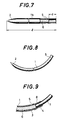
- Fig. 7 is a partially sectional front view showing the rear end of the inner core material fixed to the suturing needle,
- Fig. 8 is a front view showing the suturing needle curved in a prescribed shape, and
- Fig. 9 is a sectional view of the essential portion showing a detailed suture mount of the suturing needle.
- Fig. 10 is a sectional front view corresponding to Fig. 5 showing another embodiment of a suturing needle with suture according to the present invention.
- Fig. 11 is a sectional front view corresponding to Fig. 4 showing still another embodiment of a suturing needle with suture according to the present invention.
- Fig. 12 is a partially sectional front view showing the detailed mount of the inner core material and the suture in the embodiment of Fig. 11.
- Fig. 13 is a partially sectional front view showing a modified embodiment of Fig. 12.
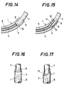
- Fig. 14 is a sectional view of the essential portion corresponding to Fig. 9 showing another embodiment of the mount of the inner core material and the suture.
- Fig. 15 is a sectional view of the essential portion corresponding to Fig. 9 showing still another embodiment of the mount of the inner core material and the suture.
- Fig. 16 is a perspective view of the essential portion showing one embodiment in which a suture cutter is formed at the edge on the needle root side of a suturing needle.
- Fig. 17 is a perspective view of the essential portion showing another embodiment in which a suture cutter is formed at the edge on the needle root side.
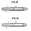
- Fig. 18 is a partially sectional front view showing a form of needle point when a suturing needle is produced by the other method.
- Fig. 19 is a partially sectional view showing another embodiment of Fig. 18.
- Fig. 1 through Fig. 9 of the accompanying drawings show one embodiment of the present invention, wherein a most popular case of a so-called round needle formed of a suturing needle curved in a circular arc is shown.
- In Fig. 1, the
suturing needle 1 is formed of a singlehollow tube 1a and a flexibleinner core material 6 inserted into a hollow slit or interior 4 thereof. - The
inner core material 6 is fixed to a point of theneedle 1 at its one end and the other end is fixed with a caulking or sealingportion 5 at aroot 3 of theneedle 1. Thepoint 2 of thesuturing needle 1 is formed by welding one end of thehollow tube 1a and one end of theinner core material 6 inserted into the hollow slit 4, fixing by means of pressing or by any other fixing means and swaging the tip portion of the fixedhollow tube 1a and theinner core material 6. - In the hollow slit 4 of the
needle root 3, one end of asuture 7 is fixed integrally in abutment with theinner core material 6 by means of caulking pressing, swaging, or by any other fixing means. - Also, when a body tissue to be sutured is stiff, a sectional shape of the
needle 1 is formed such that, for example, generally one third of the total length (needle point) on the needle point side makes a triangle, succeeding portion in the length of about one third (middle) makes a circle and the remaining one third (rear end of the needle) makes an oval. - The
needle point 2 is formed with a point angle ϑ of a prescribed size at its tip, and an apex of the triangular section at the needle point is formed with a cutter blade. - Meanwhile, when the body tissue to be sutured is soft, a circular shape is more suitable than a square as the sectional shape of the needle point.
- Next, production procedures of the suturing needle with suture according to the present invention will be explained (refer to Fig. 2 through Fig. 9).
- As the hollow tube which is a material for the needle win this case, stainless steel in the group of SUS 304 of the Japanese Industrial Standard (JIS) is utilized.
- (1) After straightening the rolled
hollow tube 1a having a reduced diameter, it is cut into a unit length L (refer to Fig. 2).
The unit length L in this case is, as shown in Fig. 3, decided by taking into account the length ℓ (8--50 mm) of the suturing needle as the finished product and the grip length at tip swaging or the like. - (2) Into the
hollow tube 1a-cut into the unit length L, the flexibleinner core material 6 having the length shorter by d than the needle length ℓ is inserted (refer to Fig. 4).
The length d is decided mainly by taking into account the inserting length of thesuture 7 fixed within the hollow slit 4 at the needle root 3 (for example 4--5 mm).
Also, as a material for theinner core material 6, a metal or non-metal different from thehollow tube 1a may be utilized besides stainless steel of SUS 301 or SUS 304 of the same group as thehollow tube 1a. - (3) When the
inner core material 6 is formed by the stainless steel SUS 301 or SUS 304 of the same group as thehollow tube 1a, one end of thehollow tube 1a is fixed integrally with theinner core material 6 by means of welding, pressing or any other fixing means.
In the next place, the integral portion is swaged at the tip to form theneedle point 2, thereby forming theneedle body 1b (refer to Fig. 5). In addition, when forming theneedle point 2, in order to raise the product value, theinner core material 6 is made so as not to be exposed from thehollow tube 1a. Also, in this case, one end of theinner core material 6 may be made slightly inward from the end surface of thehollow tube 1a to form theneedle point 2 by welding, pressing or any other fixing means and swaging.
Meanwhile, when theinner core material 6 is made of the metal or non-metal different from thehollow tube 1a, as shown in Fig. 10, one end of thehollow tube 1a is roughly reduced to form a tapered tip 1c. Then, theinner core material 6 having substantially the same shape as the tapered tip 1c is inserted into thehollow tube 1a, which are both swaged at the tips to form theneedle point 2, thereby forming theneedle body 1b. In addition, similarly to the aforementioned, when forming theneedle point 2, theinner core material 6 is made so as not to be exposed from thehollow tube 1a (refer to Fig. 5). - (4) When producing the round needle, a nose shape is formed at the tip by grinding. When producing the square needle, the needle point or about one third of the total length on the needle point side is triangularly pressed to form a cutting edge. The needle point of the
needle body 1b formed with the nose and the cutting edge is roughly ground, and theneedle body 1b is cut at the position of the needle length ℓ from the needle point (refer to Fig. 6). - (5) A periphery of the
needle body 1b corresponding to the rear end of theinner core material 6 is caulked, pressed or swaged, or in some way fixed, thereto at the caulked or fixing portion 5 (refer to Fig. 7). Moreover, theneedle body 1b is pressed and given a curved shape such as the semicircular or 3/8 circular shape to form the needle 1 (refer to Fig. 8). In the meantime, curling of theneedle body 1b may be executed before caulking and fixing the rear end of theinner core material 6 aforementioned.
Thesuturing needle 1 curved in a prescribed shape is heat treated (e.g. at 300oC for 10 minutes) if necessary to increase its hardness as well as strength. - (6) The
suturing needle 1 curved or heat treated is provided with a surface finish such as an electrolytic grinding and washing to remove slight damage caused on the surface during curving or discoloration resulting from the heat treatment. An ultrasonic or fluoride washing may be utilized as the washing. - (7) The
suture 7 is inserted into the hollow slit 4 at the rear end of theneedle 1 and fixed with the caulking or fixingportion 8 of theneedle 1 at the inserted portion (refer to Fig. 9 and Fig. 1). - Meanwhile, the
suture 7 may be fixed, as shown in Fig. 14, by expanding the hollow slit 4 to form asuture fixing hole 9 and to adhere the contact surface with theinner core material 6 by means of an adhesive 10, or as shown in Fig. 15, by forming a notchedface 11 partly on the side of thesuture 7 to overlap theinner core material 6 thereon for caulking, pressing or swaging, or by using the adhesive 10 together. - The production procedures mentioned heretofore may be employed also in the hollow tube made of a stainless material such as stainless steel in SUS 301 group or titanium besides stainless steel in SUS 304 group as the material of the
suturing needle 1. When, however, the material such as silicoroy having a sufficient hardness is used as the material of theneedle 1, heat treatment and electrolytic grinding processes among the above production procedures may be omitted. - In this embodiment, since the
suturing needle 1 is formed with thehollow tube 1a, and at production, a prepared hole for fixing thesuture 7 does not require to be opened at the rear end of theneedle 1 or further to be expanded, fixing of thesuture 7 is considerably simplified. - In addition, into the hollow slit 4 of the
needle 1, theinner core material 6 fixed by theneedle point 2 andneedle root 3 is inserted. Therefore, theneedle 1 is not only strengthened by theinner core material 6, but even if theneedle 1 is broken for any reason during operation, by pulling a portion of theneedle 1 remaining outside the tissue, broken pieces linked together with theinner core material 6 can be easily extracted. - Also, the
needle point 2 of theneedle 1 is annealed when welding one end of thehollow tube 1a, so that it can be easily formed by tip swaging. Besides, the surface hardness of theneedle point 2 thus formed is not increased so excessively as to lose its tenacity, and thus the resistance force against shock is strengthened. - In addition, when forming the
needle 1 with thehollow tube 1a, theinner core material 6 can be inserted into the hollow tube 4 of theneedle 1 without disposing a groove generally throughout the total length thereof. Therefore, the needle surface is free from any flow caused by the groove and grinding of the nose and cutting edge is performed sufficiently, and thus asharp suturing needle 1 having a smooth surface can be provided. - In the meantime, since the
suture 7 is fixed to the rear end of theneedle 1 in the last stage of heat treatment, thesuture 7 is not damaged or discolored by the high temperature. - Fig. 11 and Fig. 12 show another embodiment of the present invention, wherein an
inner core material 6A is inserted into a hollow slit or interior 4A formed inside a doublehollow tube suture 7A are respectively fixed with a caulking or fixingportion 5A and 8A of the doublehollow tube - When forming the
suturing needle 1 in such a manner, in addition to advantages obtained by the embodiment aforementioned, overlapping of poor material portions of thehollow tubes suturing needle 1. - Also, if a material used in the inner
hollow tube 1B is lower in cost than that of the outerhollow tube 1A, the material cost can be reduced compared with a single tube needle having the same thickness. - Fig. 13 shows still another embodiment of the present invention, wherein an
inner core material 6B is inserted into a hollow slit or interior 4B formed inside thehollow tubes portion 5B of thehollow tubes suture 7B is fixed with a caulking or fixingportion 8B of the outerhollow tube 1A slightly longer than the innerhollow tube 1C. - When the
suturing needle 1 is formed in such a manner, in addition to advantages obtained by the embodiment shown in Fig. 11 and Fig. 12, the diameter of thesuture 7B fixed to theneedle 1 can be enlarged to decrease a difference with the outside diameter of theneedle 1. Thus the strength of thesuture 7B fixed to theneedle 1 having the same size can be strengthened at suturing. - Fig. 16 and Fig. 17 show another different embodiment of the present invention, wherein a
suture cutter needle 1 of each embodiment aforementioned. - That is to say, in Fig. 16, the
suture cutter 12 is formed circularly at the edge of theneedle root 3 of theneedle 1 in a right angle to the lengthwise direction, while in Fig. 17, thesuture cutter 13 is formed ovally at the edge formed by cutting theneedle root 3 diagonally. Meanwhile, thesuture cutter - When the
suture cutter needle root 3, during suturing operation or after operation, if theneedle 1 is turned in a direction normal to thesuture 7 while stretching it, thesuture 7 may be easily cut with thecutter - In the meantime, in each embodiment mentioned above, the
suturing needle 1 formed by thehollow tube 1a cut into the unit length L and inserted with theinner core material 6 slightly shorter than its length is explained. - The
suturing needle 1, however, may be formed by the same production procedures aforementioned in such a manner that, thehollow tube 1a having a reduced diameter is cut, for example, into a long piece of 1--3 m, whose hollow slit 4 is inserted with theinner core material 6 having the same length and cut into the unit length L together. - In this case, since opposite ends of the
hollow tube 1a having the unit length L hold both ends of theinner core material 6 lightly by the biassing force at cutting, the needle point can be formed by swaging one end of thehollow tube 1a as it is. However, as shown in Fig. 18, by applying the biassing force to one end of theinner core material 6 in this state, and after moving said one end slightly inward from the end surface thereof, swaging one end of thehollow tube 1a at this portion, the needle point can be formed efficiently. Then, when the other end of thehollow tube 1a is cut into the needle length and the suture is fixed to the suture fixing hole provided at the needle root on the other end, the suturing needle with suture is formed. - However, in place of indenting the
inner core material 6, as shown in Fig. 19, one end of thehollow tube 1a may be bored conically. Then one end of theinner core material 6 gets slightly inside the end surface of thehollow tube 1a, and thus by swaging the same, the needle point from which theinner core material 6 is not exposed can be easily formed. - When producing the suturing needle by cutting into the unit length after inserting the inner core material into the long hollow tube in such a manner, the needle can be produced with less trouble compared with the case where the inner core material is inserted into the hollow tube cut into the unit length in advance.
- In the meantime, specific embodiments explained in the detailed description of the present invention are for illustrative purposes of clarifying the present technique. Therefore, it is to be understood that the present invention is not limited only to the specific embodiments aforementioned and construed narrowly, but rather to be construed broadly that various changes and modifications may be made without departing from the spirit of the present invention and the scope of the appended claims.
Claims (12)
- A method of producing a suturing needle (1), comprising inserting a core (6) into a tube (1a) having an outer diameter substantially equal to that of the finished needle (1), fixing the core (6) to the tube (1a) leaving a suture-fixing hole in an end of the tube (1a), forming a point (2) and fixing the end portion (4) of the suture (7) in the suture-fixing hole, characterised in that one end of the tube (1a) is fixed to the core (6), the point (2) being formed on the said one end of the tube (1a), and in that the core (6) is fixed to the tube (1a) at the other end of the tube.
- A method of producing a suturing needle (1) in accordance with Claim 1 wherein the tube (1a) is cut to the length of the finished needle (1) after the point (2) is formed.
- A method of producing a suturing needle (1) in accordance with Claim 1 or 2, wherein the needle (1) is curved to a prescribed shape before the suture (7) is fixed in the suture-fixing hole (4).
- A method of producing a suturing needle (1) in accordance with Claim 1, 2 or 3, wherein one end of the tube (1a) is swaged to form the needle point (2).
- A method of producing a suturing needle (1) in accordance with any of the preceding Claims, wherein the needle point (1) is formed after integrally fixing one end of the tube (1a) and the core (6) by welding.
- A method of producing a suturing needle (1) in accordance with any of the preceding Claims, wherein the fixing process is caulking.
- A method of producing a suturing needle (1) in accordance with any of the preceding Claims, wherein the needle (1) with the core (6) fixed is given a heat treatment to harden the needle (1) to a required value after being curved into a prescribed shape.
- A method of producing a suturing needle (1) in accordance with any of the preceding Claims, wherein the suture fixing hole (4) of the needle is formed by slightly expanding the other end of the tube (1a).
- A method of producing a suturing need (1) in accordance with any of the preceding Claims, wherein before cutting a long hollow tube into a unit length for forming the needle (1), the core (6) is inserted into said hollow tube.
- A method of producing a suturing needle (1) in accordance with any of the preceding Claims wherein after cutting a long hollow tube into a unit length for forming the needle (1), the core (6) is inserted into said hollow tube.
- A method of producing a suturing needle (1) in accordance with any of the preceding Claims, wherein after moving one end of the core (6) slightly inside from said one end of the tube (1a), said one end of the core (6) is fixed so as not to be exposed from the tube (1a).
- A method of producing a suturing needle (1) in accordance with any of the prededing Claims, wherein the core (6) is fixed to the tube (1a) at the other end of the tube (1a) by caulking, pressing, welding or swaging.
Applications Claiming Priority (6)
| Application Number | Priority Date | Filing Date | Title |
|---|---|---|---|
| JP136758/86 | 1986-06-12 | ||
| JP61136758A JPH0741041B2 (en) | 1986-06-12 | 1986-06-12 | Suture needle with thread and manufacturing method thereof |
| JP61224664A JPH0744933B2 (en) | 1986-09-22 | 1986-09-22 | Method for manufacturing suture needle with thread |
| JP224664/86 | 1986-09-22 | ||
| JP61279250A JPH0822285B2 (en) | 1986-11-21 | 1986-11-21 | Suture needle with thread and manufacturing method thereof |
| JP279250/86 | 1986-11-21 |
Related Parent Applications (1)
| Application Number | Title | Priority Date | Filing Date |
|---|---|---|---|
| EP87305264.1 Division | 1987-06-12 |
Publications (2)
| Publication Number | Publication Date |
|---|---|
| EP0553891A2 true EP0553891A2 (en) | 1993-08-04 |
| EP0553891A3 EP0553891A3 (en) | 1994-04-06 |
Family
ID=27317335
Family Applications (2)
| Application Number | Title | Priority Date | Filing Date |
|---|---|---|---|
| EP93104439A Ceased EP0553891A2 (en) | 1986-06-12 | 1987-06-12 | Method of producing a suturing needle with suture |
| EP87305264A Expired - Lifetime EP0249504B1 (en) | 1986-06-12 | 1987-06-12 | Suturing needle with suture |
Family Applications After (1)
| Application Number | Title | Priority Date | Filing Date |
|---|---|---|---|
| EP87305264A Expired - Lifetime EP0249504B1 (en) | 1986-06-12 | 1987-06-12 | Suturing needle with suture |
Country Status (4)
| Country | Link |
|---|---|
| US (2) | US4805292A (en) |
| EP (2) | EP0553891A2 (en) |
| KR (1) | KR950000058B1 (en) |
| DE (1) | DE3789916T2 (en) |
Families Citing this family (87)
| Publication number | Priority date | Publication date | Assignee | Title |
|---|---|---|---|---|
| US5226912A (en) | 1987-08-26 | 1993-07-13 | United States Surgical Corporation | Combined surgical needle-braided suture device |
| US4944287A (en) * | 1988-03-29 | 1990-07-31 | Asahi Kogaku Kogyo K.K. | Flexible tube of endoscope |
| JPH01317430A (en) * | 1988-06-18 | 1989-12-22 | Keisei Ika Kogyo Kk | Device for assembling surgical needle for operation |
| US4984941A (en) * | 1989-03-02 | 1991-01-15 | United States Surgical Corporation | Apparatus for forming a suture cut-off feature in a surgical needle possessing a suture-receiving socket |
| US4932963A (en) * | 1989-03-02 | 1990-06-12 | United States Surgical Corporation | Combined surgical needle-suture device possessing an integrated suture cut-off feature |
| US5123911A (en) * | 1989-09-27 | 1992-06-23 | United States Surgical Corporation | Method for attaching a surgical needle to a suture |
| US5051107A (en) * | 1989-09-27 | 1991-09-24 | United States Surgical Corporation | Surgical needle-suture attachment for controlled suture release |
| US5067959A (en) * | 1989-09-27 | 1991-11-26 | United States Surgical Corporation | Surgical needle-suture attachement for controlled suture release |
| US5280674A (en) * | 1989-09-27 | 1994-01-25 | United States Surgical Corporation | Apparatus for attaching a surgical needle to a suture |
| US5139514A (en) * | 1989-09-27 | 1992-08-18 | United States Surgical Corporation | Combined needle-suture device |
| US5089010A (en) * | 1989-09-27 | 1992-02-18 | United States Surgical Corporation | Surgical needle-suture attachment possessing weakened suture segment for controlled suture release |
| US5156615A (en) * | 1989-09-27 | 1992-10-20 | United States Surgical Corporation | Surgical needle-suture attachment for controlled suture release |
| US5133738A (en) * | 1989-09-27 | 1992-07-28 | United States Surgical Corporation | Combined surgical needle-spiroid braided suture device |
| US5102418A (en) * | 1989-09-27 | 1992-04-07 | United States Surgical Corporation | Method for attaching a surgical needle to a suture |
| US5059212A (en) * | 1989-09-27 | 1991-10-22 | United States Surgical Corporation | Surgical needle-suture attachment for controlled separation of the needle from the suture |
| US5041128A (en) * | 1989-09-27 | 1991-08-20 | United States Sirgical Corporation | Combined surgical needle-suture device possessing an integrated suture cut-off feature |
| US5084063A (en) * | 1989-09-27 | 1992-01-28 | United States Surgical Corporation | Surgical needle-suture attachment |
| US5089011A (en) * | 1989-09-27 | 1992-02-18 | United States Surgical Corporation | Combined surgical needle-suture device possessing an integrated suture cut-off feature |
| US5259845A (en) * | 1989-09-27 | 1993-11-09 | United States Surgical Corporation | Surgical needle-suture attachment with a lubricated suture tip for controlled suture release |
| US5046350A (en) * | 1989-11-03 | 1991-09-10 | United States Surgical Corporation | Apparatus for attaching surgical suture components |
| US5168619A (en) * | 1989-11-03 | 1992-12-08 | United States Surgical Corporation | Method for attaching surgical suture components |
| US5131131A (en) * | 1989-11-03 | 1992-07-21 | United States Surgical Corporation | Method for attaching surgical suture components |
| US5099676A (en) * | 1989-11-03 | 1992-03-31 | United States Surgical Corporation | Apparatus for attaching surgical suture components |
| US5358498A (en) * | 1990-02-01 | 1994-10-25 | Deknatel Technology Corporation, Inc. | Needled suture |
| US5116358A (en) * | 1990-07-23 | 1992-05-26 | United States Surgical Corporation | Combined surgical needle-suture device possessing a controlled suture separation feature |
| US5306288A (en) * | 1990-09-05 | 1994-04-26 | United States Surgical Corporation | Combined surgical needle-suture device |
| US5183063A (en) * | 1991-06-10 | 1993-02-02 | Larry Lee Ringle | Dental floss and pre-threaded leader |
| US5236443A (en) * | 1992-05-21 | 1993-08-17 | Sidney Sontag | Suturing assembly and method |
| US5180385A (en) * | 1992-05-21 | 1993-01-19 | Sidney Sontag | Suturing assembly and method |
| US5350373A (en) * | 1992-10-09 | 1994-09-27 | United States Surgical Corporation | Apparatus for attaching surgical suture components |
| US5394971A (en) * | 1993-08-02 | 1995-03-07 | United States Surgical Corporation | Apparatus for attaching surgical suture components |
| US5304184A (en) * | 1992-10-19 | 1994-04-19 | Indiana University Foundation | Apparatus and method for positive closure of an internal tissue membrane opening |
| US5342325A (en) * | 1992-12-07 | 1994-08-30 | Dlp, Incorporated | Introducer needle and catheter assembly |
| US5632753A (en) * | 1992-12-31 | 1997-05-27 | Loeser; Edward A. | Surgical procedures |
| US5403346A (en) * | 1992-12-31 | 1995-04-04 | Loeser; Edward A. | Self-affixing suture assembly |
| US5384945A (en) * | 1993-04-21 | 1995-01-31 | United States Surgical Corporation | Device for forming drilled needle blanks |
| US5383902A (en) * | 1993-06-02 | 1995-01-24 | United States Surgical Corporation | Surgical needle-suture attachment for controlled suture release |
| US5411613A (en) * | 1993-10-05 | 1995-05-02 | United States Surgical Corporation | Method of making heat treated stainless steel needles |
| US5403345A (en) * | 1993-10-12 | 1995-04-04 | United States Surgical Corporation | Needle suture attachment |
| AU7594794A (en) * | 1993-10-22 | 1995-05-11 | Ethicon Inc. | Surgical suture needle of the taper point type |
| AU5069796A (en) * | 1995-04-28 | 1996-11-07 | Ethicon Inc. | Solventless tipping of braided surgical ligature |
| US5707391A (en) * | 1995-06-07 | 1998-01-13 | United States Surgical Corporation | Apparatus and method for attaching surgical needle suture components |
| US5722991A (en) * | 1995-06-07 | 1998-03-03 | United States Surgical Corporation | Apparatus and method for attaching surgical needle suture components |
| US5716392A (en) * | 1996-01-05 | 1998-02-10 | Medtronic, Inc. | Minimally invasive medical electrical lead |
| US5911449A (en) * | 1997-04-30 | 1999-06-15 | Ethicon, Inc. | Semi-automated needle feed method and apparatus |
| US6381495B1 (en) | 1997-05-28 | 2002-04-30 | Transneuronix, Inc. | Medical device for use in laparoscopic surgery |
| US6477423B1 (en) | 1997-05-28 | 2002-11-05 | Transneuronix, Inc. | Medical device for use in laparoscopic surgery |
| IT1292016B1 (en) * | 1997-05-28 | 1999-01-25 | Valerio Cigaina | IMPLANT DEVICE PARTICULARLY FOR ELECTROSTIMULATION AND / OR ELECTRO-REGISTRATION OF ENDOABDOMINAL VISCERS |
| US6321124B1 (en) | 1997-05-28 | 2001-11-20 | Transneuronix, Inc. | Implant device for electrostimulation and/or monitoring of endo-abdominal cavity tissue |
| IT1301986B1 (en) * | 1998-07-31 | 2000-07-20 | Valerio Cigaina | LAPAROSCOPIC FORCEPS FOR SUTURE. |
| IT1313608B1 (en) | 1999-08-06 | 2002-09-09 | Valerio Cigaina | EQUIPMENT FOR STIMULATION OF A COMPLETE STATE OF CONTINENCE OF THE NEOSFINTER IN THE PACK OF CONTINENT NEOSTOMIES AND |
| US6510332B1 (en) | 1999-08-30 | 2003-01-21 | Transneuronix, Inc. | Electrode leads for use in laparoscopic surgery |
| US7096070B1 (en) | 2000-02-09 | 2006-08-22 | Transneuronix, Inc. | Medical implant device for electrostimulation using discrete micro-electrodes |
| US6588723B1 (en) | 2000-06-30 | 2003-07-08 | Cfm Corporation | Decoratively aesthetic shepherd hook |
| US20020072780A1 (en) * | 2000-09-26 | 2002-06-13 | Transneuronix, Inc. | Method and apparatus for intentional impairment of gastric motility and /or efficiency by triggered electrical stimulation of the gastrointestinal tract with respect to the intrinsic gastric electrical activity |
| US20060206160A1 (en) * | 2000-11-15 | 2006-09-14 | Transneuronix, Inc. | Process and electrostimulation device for treating obesity and/or gastroesophageal reflux disease |
| US6615084B1 (en) | 2000-11-15 | 2003-09-02 | Transneuronix, Inc. | Process for electrostimulation treatment of morbid obesity |
| US20030120328A1 (en) * | 2001-12-21 | 2003-06-26 | Transneuronix, Inc. | Medical implant device for electrostimulation using discrete micro-electrodes |
| WO2004006988A2 (en) * | 2002-07-17 | 2004-01-22 | Tyco Healthcare Group Lp | Union stress needle |
| US20040088022A1 (en) * | 2002-07-26 | 2004-05-06 | Transneuronix, Inc. | Process for electrostimulation treatment of morbid obesity |
| US7185524B2 (en) * | 2003-08-14 | 2007-03-06 | Tyco Healthcare Group Lp | Grindless surgical needle manufacture |
| US7481826B2 (en) * | 2003-09-30 | 2009-01-27 | Ethicon, Inc. | Fluid emitting suture needle |
| US7353683B2 (en) * | 2004-02-20 | 2008-04-08 | Tyco Healthcare Group Lp | Surgical needle manufacturing process |
| US20050222637A1 (en) * | 2004-03-30 | 2005-10-06 | Transneuronix, Inc. | Tachygastrial electrical stimulation |
| US20050222638A1 (en) * | 2004-03-30 | 2005-10-06 | Steve Foley | Sensor based gastrointestinal electrical stimulation for the treatment of obesity or motility disorders |
| US7559952B2 (en) * | 2004-12-17 | 2009-07-14 | Innovia, Llc | Elastomeric polymer filament cosmetic implant |
| JP4801367B2 (en) * | 2005-03-31 | 2011-10-26 | マニー株式会社 | Manufacturing method of eyeless suture needle |
| US20060247718A1 (en) * | 2005-04-28 | 2006-11-02 | Medtronic, Inc. | Dual mode electrical stimulation to treat obesity |
| US20070010855A1 (en) * | 2005-07-05 | 2007-01-11 | Florez Mendez Maximiliano E | Facial lifting needle and method thereof |
| US8292920B2 (en) * | 2005-11-10 | 2012-10-23 | Tyco Healthcare Group Lp | Sickle needle and method |
| US7415858B2 (en) | 2006-02-21 | 2008-08-26 | Tyco Healthcare Group Lp | Grindless surgical needle manufacture |
| WO2007136712A2 (en) * | 2006-05-17 | 2007-11-29 | Medtronic, Inc. | Electrical stimulation therapy to promote gastric distention for obesity management |
| US9198562B2 (en) * | 2008-06-17 | 2015-12-01 | Apollo Endosurgery, Inc. | Endoscopic needle assembly |
| US11812951B2 (en) | 2008-06-17 | 2023-11-14 | Apollo Endosurgery Us, Inc. | Endoscopic needle assembly |
| US8538532B2 (en) * | 2009-03-03 | 2013-09-17 | Medtronic, Inc. | Electrical stimulation therapy to promote gastric distention for obesity management |
| BR112012001910A2 (en) * | 2009-09-21 | 2019-09-24 | Medtronic Inc | waveforms for electrical stimulation therapy |
| EP2571548B1 (en) * | 2010-05-17 | 2018-04-18 | MiMedx Group, Inc. | Compressible tubes for placing implants and related medical kits and methods of using same |
| US9161751B2 (en) | 2010-12-02 | 2015-10-20 | Coloplast A/S | Suture system and assembly |
| US8568428B2 (en) * | 2011-01-05 | 2013-10-29 | Coloplast A/S | Suture system and assembly including a tubular leader having a clasp |
| US9220495B2 (en) | 2011-02-10 | 2015-12-29 | Coloplast A/S | Suture system and assembly including a suture clip |
| US8591528B2 (en) | 2011-02-24 | 2013-11-26 | Coloplast A/S | Suture system and assembly including a suture cap formed around a tubular sleeve |
| KR101132841B1 (en) * | 2011-03-07 | 2012-04-02 | 김영재 | A suture |
| KR101185583B1 (en) | 2011-12-27 | 2012-09-24 | 김영재 | A suture which need not be knotted and a kit comprising the suture |
| US10178990B2 (en) | 2012-12-05 | 2019-01-15 | Y. Jacobs Medical Inc. | Apparatus for inserting surgical thread, and surgical procedure kit for inserting surgical thread comprising same |
| US10010317B2 (en) | 2012-12-05 | 2018-07-03 | Young Jae Kim | Method of improving elasticity of tissue of living body |
| JP6145580B2 (en) | 2013-12-06 | 2017-06-14 | ワイ.ジェイコブス メディカル インコーポレーテッド | Medical tube insertion device and medical tube insertion treatment kit including the same |
| US9597507B2 (en) | 2014-10-31 | 2017-03-21 | Medtronic, Inc. | Paired stimulation pulses based on sensed compound action potential |
Citations (3)
| Publication number | Priority date | Publication date | Assignee | Title |
|---|---|---|---|---|
| JPS4612549Y1 (en) | 1969-05-08 | 1971-05-01 | ||
| JPS5915648B2 (en) | 1977-04-15 | 1984-04-11 | 株式会社松谷製作所 | medical suture |
| JPS61103438A (en) | 1984-10-26 | 1986-05-21 | ナカムラ産業株式会社 | Suturing needle with yarn and its production |
Family Cites Families (18)
| Publication number | Priority date | Publication date | Assignee | Title |
|---|---|---|---|---|
| US383733A (en) * | 1888-05-29 | Method of making needles | ||
| US1613206A (en) * | 1921-04-07 | 1927-01-04 | Souttar Henry Sessions | Surgical needle |
| US1591021A (en) * | 1924-09-27 | 1926-07-06 | Davis & Geck Inc | Needle |
| US1844364A (en) * | 1931-01-12 | 1932-02-09 | Robert J Lowrie | Needle |
| US2022234A (en) * | 1933-03-18 | 1935-11-26 | Everett Norah Elizabeth | Surgical and like needle and its manufacture |
| US2411079A (en) * | 1944-09-09 | 1946-11-12 | Gerhard H J Baule | Method of attaching sutures to shanks of surgeons' needles |
| GB670199A (en) * | 1949-06-21 | 1952-04-16 | Samuel James Everett | Improvements relating to surgical, suture and like sewing needles |
| US2839824A (en) * | 1950-03-24 | 1958-06-24 | Amp Inc | Method of severing pin type connectors from strips thereof |
| FR1041290A (en) * | 1950-08-23 | 1953-10-22 | S & R J Everett & Co Ltd | Advanced surgical needle |
| US2795832A (en) * | 1953-06-22 | 1957-06-18 | Zinke Erwin Max | Hook |
| US3109231A (en) * | 1960-06-20 | 1963-11-05 | Hexacon Electric Company | Method of producing soldering tips for electric soldering irons |
| GB1121944A (en) * | 1966-02-07 | 1968-07-31 | Braun Kommanditgesellschaft B | Eyeless needles and process for their production |
| US3716902A (en) * | 1970-02-18 | 1973-02-20 | Small Tube Products | Method of making a composite welding torch tip |
| US3807015A (en) * | 1970-12-16 | 1974-04-30 | Ibm | Method of making a compact fluid actuator |
| US4140125A (en) * | 1976-02-25 | 1979-02-20 | Med-Pro, Ltd. | Surgical tape device |
| US4054144A (en) * | 1976-05-28 | 1977-10-18 | American Cyanamid Company | Short-crimp surgical needle |
| DE2905398A1 (en) * | 1979-02-13 | 1980-08-14 | Josef W Ing Grad Kappenstein | Composite surgical needle - comprises corrosion resistant sleeve and core wire fused together at needle end |
| EP0232444A1 (en) * | 1986-02-19 | 1987-08-19 | Yasuo Nakamura | A suture needle and its manufacturing processes |
-
1987
- 1987-06-11 KR KR1019870005929A patent/KR950000058B1/en not_active IP Right Cessation
- 1987-06-12 EP EP93104439A patent/EP0553891A2/en not_active Ceased
- 1987-06-12 DE DE3789916T patent/DE3789916T2/en not_active Expired - Fee Related
- 1987-06-12 EP EP87305264A patent/EP0249504B1/en not_active Expired - Lifetime
- 1987-12-30 US US07/140,779 patent/US4805292A/en not_active Expired - Fee Related
-
1989
- 1989-01-11 US US07/349,931 patent/US4901722A/en not_active Expired - Fee Related
Patent Citations (3)
| Publication number | Priority date | Publication date | Assignee | Title |
|---|---|---|---|---|
| JPS4612549Y1 (en) | 1969-05-08 | 1971-05-01 | ||
| JPS5915648B2 (en) | 1977-04-15 | 1984-04-11 | 株式会社松谷製作所 | medical suture |
| JPS61103438A (en) | 1984-10-26 | 1986-05-21 | ナカムラ産業株式会社 | Suturing needle with yarn and its production |
Also Published As
| Publication number | Publication date |
|---|---|
| EP0249504A3 (en) | 1988-06-08 |
| KR880000064A (en) | 1988-03-23 |
| KR950000058B1 (en) | 1995-01-09 |
| EP0249504B1 (en) | 1994-06-01 |
| DE3789916T2 (en) | 1995-02-16 |
| US4805292A (en) | 1989-02-21 |
| EP0553891A3 (en) | 1994-04-06 |
| EP0249504A2 (en) | 1987-12-16 |
| DE3789916D1 (en) | 1994-07-07 |
| US4901722A (en) | 1990-02-20 |
Similar Documents
| Publication | Publication Date | Title |
|---|---|---|
| US4901722A (en) | Suturing needle with suture | |
| US3160157A (en) | Surgical needle | |
| US3910282A (en) | Needling monofilament sutures | |
| CA2122418C (en) | Surgical suturing needle and method for making same | |
| US6322581B1 (en) | Suturing needle for medical use | |
| JP4485363B2 (en) | Sharp tip needle | |
| US20070219586A1 (en) | Suture Needle and Suture Assembly | |
| EP0107961A1 (en) | Hard tissue surgical needle | |
| EP0582276A1 (en) | Needles made from non-round stock | |
| EP1506743B1 (en) | Grindless surgical needle manufacture | |
| JP2000139931A (en) | Micro-suturing needle and its manufacture | |
| JP2599090B2 (en) | Suture needle, suture needle with thread, and method of manufacturing the same | |
| EP1566230B1 (en) | Surgical needle manufacturing process | |
| JP2005532873A (en) | Surgical SE suture needle | |
| JP2006061453A (en) | Suture thread with needle | |
| JPS63132646A (en) | Suturing needle with yarn and its production | |
| US20230371944A1 (en) | Composite suture needles having elastically deformable sections | |
| JPS62159646A (en) | Suturing needle with suture and its production | |
| JPS62122648A (en) | Suturing needle with yarn and its production | |
| JP3684327B2 (en) | Suture needle with thread | |
| JPH0744933B2 (en) | Method for manufacturing suture needle with thread | |
| JPS62292145A (en) | Suturing needle with yarn and its production | |
| JPS63177846A (en) | Suturing needle and its production | |
| JPH0323889A (en) | Manufacture of sewing needle with yarn |
Legal Events
| Date | Code | Title | Description |
|---|---|---|---|
| PUAI | Public reference made under article 153(3) epc to a published international application that has entered the european phase |
Free format text: ORIGINAL CODE: 0009012 |
|
| 17P | Request for examination filed |
Effective date: 19930331 |
|
| AC | Divisional application: reference to earlier application |
Ref document number: 249504 Country of ref document: EP |
|
| AK | Designated contracting states |
Kind code of ref document: A2 Designated state(s): DE FR GB IT |
|
| PUAL | Search report despatched |
Free format text: ORIGINAL CODE: 0009013 |
|
| AK | Designated contracting states |
Kind code of ref document: A3 Designated state(s): DE FR GB IT |
|
| 17Q | First examination report despatched |
Effective date: 19941229 |
|
| STAA | Information on the status of an ep patent application or granted ep patent |
Free format text: STATUS: THE APPLICATION HAS BEEN REFUSED |
|
| 18R | Application refused |
Effective date: 19950619 |