EP0554986B1 - Surface mount outlet - Google Patents
Surface mount outlet Download PDFInfo
- Publication number
- EP0554986B1 EP0554986B1 EP93300400A EP93300400A EP0554986B1 EP 0554986 B1 EP0554986 B1 EP 0554986B1 EP 93300400 A EP93300400 A EP 93300400A EP 93300400 A EP93300400 A EP 93300400A EP 0554986 B1 EP0554986 B1 EP 0554986B1
- Authority
- EP
- European Patent Office
- Prior art keywords
- plates
- cover
- base
- enclosure
- cable
- Prior art date
- Legal status (The legal status is an assumption and is not a legal conclusion. Google has not performed a legal analysis and makes no representation as to the accuracy of the status listed.)
- Expired - Lifetime
Links
Images


Classifications
-
- H—ELECTRICITY
- H02—GENERATION; CONVERSION OR DISTRIBUTION OF ELECTRIC POWER
- H02G—INSTALLATION OF ELECTRIC CABLES OR LINES, OR OF COMBINED OPTICAL AND ELECTRIC CABLES OR LINES
- H02G3/00—Installations of electric cables or lines or protective tubing therefor in or on buildings, equivalent structures or vehicles
- H02G3/02—Details
- H02G3/08—Distribution boxes; Connection or junction boxes
- H02G3/10—Distribution boxes; Connection or junction boxes for surface mounting on a wall
Definitions
- the invention relates to an outlet for communications cable and for holding receptacle connectors to which apparatus including telephones and computers can be plugged and unplugged with ease.
- Telephone cable represents one type of communications cable linking together telephones in various offices and work areas. Computers in various offices and work areas are linked to one another by communications cable that can be coaxial cable and fiber optic cable, for example.
- An outlet is a device located along the communications cable providing a convenient place to plug in the telephones and computers.
- the telephones and computers have plug type data connectors for plugging into receptacle type data connectors.
- the outlet must be constructed with the receptacle type data connectors for connection on the communications cable, and for mating with the plug type data connectors of the telephones and computers.
- An outlet for communications cable resides in an enclosure defined by a base, multiple sides, a cover for covering the enclosure, and a cable receiving opening in the base, and is characterised by multiple interchangeable plates mountable along the sides of the enclosure, each of the plates being removable for replacement by one of the plates having a connector receiving opening adapted to receive a data connector terminated to a cable received by the cable receiving opening.
- the invention is able to fulfil a need for an outlet that is readily adaptable with data connectors of different types and for connection to communications cable of different types. It further permits ease of installation of various types of data connectors in an outlet.
- the outlet is adapted for mounting to a floor, or to single or double ganged outlet wall boxes, or to a plaster ring used to mount such boxes, or to an item of furniture, and for providing outlets for data cable in the corresponding floor, outlet box, plaster ring or item of furniture.
- an outlet 1 for communications cable comprises an enclosure 2 covered by and defined by a base 3 and a cover 4 and multiple plates 5 , Figures 1, 3 and 6.
- the base 3 and the cover 4 are constructed such that the horizontal surfaces are exposed on both, top and bottom sides, so as to be capable of being molded between straight draw molding dies, not shown.
- the vertical surfaces of the base 3 and the cover 4 are straight, so as to be capable of being molded by straight draw molding dies.
- the plates 5 shown in Figure 1 are each blank, without an opening.
- the plates 5 of Figure 6 are provided with connector receiving openings 6 constructed with various connector receiving shapes adapted to receive respective electrical data connectors, not shown, of different shapes and sizes.
- the data connectors are of known types for connecting to different electrical and optical communications cables that transmit data rather than electrical power.
- Such connectors are known, for example, from US-A-4,795,356, requiring a correspondingly shaped opening 6 in one of the plates 5, from US-A-4,884,982, requiring a correspondingly shaped opening 6 in one of the plates 5, from U-S-A-4,659,166, disclosing multiple connectors, two of which can be received in multiple openings 6 in one of the plates 5.
- Other plates 5 are adapted with openings 6 for receiving other connectors, not shown.
- the base 3 is of unitary, one piece, construction, molded from plastics material.
- a bottom 7 of the base 3 has an enlarged, circular, cable receiving opening 8 intersected by smaller, rectangular openings 9 .
- the bottom 7 provides an exterior mounting surface adapted for attachment to a floor, or wall box or plaster ring, or an item of furniture, not shown.
- the base 3 is provided with apertures 10 , Figure 4, encircled by reinforcing bosses 11 , and through which fasteners 12 , Figure 5, can project for attaching the base 3.
- a knock out plate 13 , Figure 4, is defined by segmented slits 14 through the bottom 7 separated from one another by thin webs.
- the webs are frangible, whereby the knock out plate 13 is removable to create a cable receiving opening for placement against an item of furniture.
- One of the slits 14 is wide enough to receive a prying tool, not shown, such as the shank of a screwdriver, to pry the knock out plate 13 and break the webs.
- a raised reinforcing rib encircling the cable receiving opening 8 projects into the enclosure 2 and defines a spindle 15 of a bobbin 16 , Figure 5, for winding a communications cable 17 emerging from a floor or an item of furniture and received in CL rectangular opening 9, both the rectangular openings 9 extending through the spindle 15 and communicating with the cable receiving opening 8.
- Segmented flanges 18 of the bobbin 16 overlap the spindle 15.
- the flanges 18 are spaced from the bottom 7 of the base 3 and are opposite corresponding openings 19 through the bottom 7 shaped like the edges of the flanges 18.
- the openings 19 in the bottom are aligned with the flanges 18, through which openings 19 are inserted mold core pins, not shown, for forming the flanges 18 integral with the spindle 15 during a plastics molding operation.
- the cable 17 connected with an electrical data connector 20 , Figure 5, emerging from the floor or from an item of furniture, is received by the cable receiving opening 8, and is wound part way around the spindle 15, with the cable 17 in registration with the rectangular opening 9.
- the flanges 18 overlap the cable 17 on the spindle 15. Further details of the connector 20 are disclosed in US-A-4,795,356.
- the multiple plates 5 are interchangeable. Each of the plates 5 is removable for replacement by one of the plates 5 having a selected connector receiving opening 6, for example, the opening 6 of Figures 8 and 9 adapted to receive the data connector 20 connected to the cable 17.
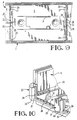
- the plates 5 are adapted for receipt in plate receiving openings 21 , Figures 3 and 8, that are partly in the base 3 and partly in the cover 4.
- Each of the plate receiving openings 21 are open along a parting line 22 , Figure 9, where the base 3 and cover 4 meet in abutment.
- the parting line 22 divides columns 23 of the enclosure 2.
- the divided columns 23, in part, are integral with the base 3 and, in part, are integral with the cover 4.
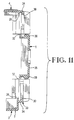
- the columns 23, Figures 4, 7 and 10 are hollow and constructed of thin, straight walls adapted for fabrication by molding as a unitary one piece cover.
- the columns 23 are spaced apart from one another and define sides of the plate receiving openings 21.
- the columns 23 further define sides of the enclosure 2 extending upwardly from the bottom 7.
- the columns 23 separate the plate receiving openings 21.
- the columns 23 on the cover 4 are stacked on the columns 23 of the base 3.
- detents 25 are recessed in bottoms of the grooves 24.
- the detents 25 are relatively near the parting line 22, such that the plates 5 are nearly fully inserted along the plate receiving openings 21 before interlocking with the base 3.
- the plates 5 are adapted to be mounted upside down, if desired.
- two projecting portions 26 are distributed, evenly spaced, across a midpoint of each of the sides of the plates 5.
- the parting line 22 intersects the midpoint.
- One of the projections 26 in each side of the plates 5 will interlock with a corresponding detent 25 when the plates 5 are mounted in corresponding positions, as shown in Figure 9, or upside down relative to that, as shown in Figure 9.
- the columns 23 of the cover 4 are comprised of recesses 28 in bottoms of the grooves 24.
- the recesses 28 face the flanges 27 of the plates 5.
- the recess 28 provide clearances, Figure 9, allowing passage of the projections 26 on the flanges 27 of the plates 5 without interlocking with the cover 4.
- the cover 4 can be mounted to the base 3 after all the plate receiving openings 21 are filled with interlocked plates 5 without dislodging the interlocked plates 5.
- Top ends of the plates 5 along the sides of the enclosure 2 define an open top of the enclosure 2. Further, the cover 4 can be removed without dislodging the interlocked plates 5 that will remain interlocked with the base 3. Replacement of the plates 5 is easily accomplished, when removal of the cover 4 will expose the contents of the enclosure 2 with the plates 5 in place on the base 3.
- top and bottom ends of the plate receiving openings 21 are defined by spaced apart, inner and outer, reinforcing ribs 29 , 30 in the base 3, Figure 4, and similarly in the cover 4, Figure 7.
- the cover 4 is of unitary one piece construction, molded from plastics material.
- the cover 4, Figure 7, has a series of raised reinforcing ribs 30' joined to the inner rib 29 and extending from each column 23 to the center of the cover 4 where the reinforcing ribs 30' intersect one another.
- the inner rib 29 of the cover 4, Figure 7, encircles the periphery of the enclosure 2.
- the inner rib 29 of the base 3, Figure 4, encircles the periphery of the enclosure 2 and is cross braced and joined at corners of the periphery by curved reinforcing ribs 31 defining an outer spindle for confining a wound communications cable.
- the outer ribs 30 span between columns 23, joining the columns 23 at the grooves 24.
- Elongated channels 32 extend along opposite ends of the plates 5 and receive the outer reinforcing ribs 30 of the base 3 and of the cover 4, the flanges 27 of the plates 5 being slidable along the grooves 24 of the base 3 until the channels 32 receive the outer rib 30 of the base 3.
- the plates 5 interlock with the detents 25 to retain the plates 5.
- the cover 4 When the cover 4 is installed over the enclosure 2, the plates 5 are slidable along the grooves 24 of the cover 4 until the channels 32 receive the outer rib 30 of the cover 4.
- the cover 4 overlaps the plates 5 and prevents removal of the plates 5.
- the ribs 30 of the base 3 extend from a ledge 33 extending around the periphery of the enclosure 2 and extending in an overhang beyond the mounting surface provided by the bottom 7.
- the rib 30 is on the ledge 33.
- a chamfer 34 is along an exterior underside of the ledge 33.
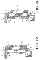
- a similar but oppositely inclined chamfer 34 of the cover 4, Figures 3 and 11, is along an exterior periphery of the cover 4 and intersects the plate receiving openings 21.
- the plates 5 each have exterior bezels 35 , Figures 11-13, adapted for receipt in the plate receiving openings 21 of the cover 4.
- top and bottom ends 36 of the bezels 35 overlap the channels 32 of the plates 5 and extend outwardly, top and bottom, beyond the channels 32 to fill the plate receiving openings 21 of the base 3 and of the cover 4.
- the bezels 35 bridge between the columns 23 to fill the plate receiving openings 21.
- the bezels 35 are adapted to be flush with the sides of the enclosure 2.
- the flanges 27 of the plates 5 extend outwardly beyond the bezels 35, Figure 8, to register in respective grooves 24 of the columns 23.
- the flanges 27 are inward behind the bezels 35 to be hidden when the bezels 35 fill the plate receiving openings 21.
- the ends 36 of the bezels are received in cut outs 37 , Figure 1, in the respective chamfers 34 of the cover 4 and of the base 3.
- the ends 36 of the bezels have chamfers flush with the chamfers 34 of the cover 4 and of the base 3.
- the plates 5 comprise a feature that prevents installation of the plates 5 inside out in the plate receiving openings 21, Figure 13.
- one end 36 of the bezel impinges against the inner rib 29 of the base 3.
- the inner rib 29 is taller than the outer rib 30 and resists movement of the plate 5 far enough to interlock the projections 26 of the flanges 27 with the detents 25.
- the projecting end 36 of the bezel 35 impinges against the taller inner rib 29 of the cover 4 to resist complete insertion of the plate 5 along the plate receiving opening 21 of the cover 4 and to prevent the cover 4 from meeting the base 3 along the parting line 22, Figure 13.
- the columns 23 of the enclosure 2 are beveled flush with the respective chamfers 34 of the cover 4 and of the base 3.
- Each column 23 at a corner of the enclosure 2 is convex and provides a corresponding curve in the sides of the enclosure 2.
- Each column 23 at a corner is smoothly beveled, following along the curve, flush with the chamfers 34, and is also smoothly curved around the corners of the cover 4 and of the base 3.
- the spindle 15, Figures 3 and 5 is braced by a channel 38 that bridges the opening 8.
- the base 3 has an integral, hollow mounting post 39 that is integral with the channel 38 and that projects outwardly from the channel 38 and from the enclosure 2 toward the cover 4.
- the cover 4, Figure 2 has a central projecting, hollow hub 41 from which projects an elongated key 42 for receipt along the keyway 40 to orient the cover 4 with the base 3.
- the hub 41 is slit partially through to provide segmented spring, gripping fingers that encircle and grip the shank of an elongated fastener 43 used to secure the cover 4 to the mounting post 39, and the fastener 43 slidably extends in the hub 41 and in the mounting post 39.
- the fastener 43 can extend through the mounting post 39 and threadably secure to an internally threaded nut, not shown, on the exterior of the bottom 7.
- the fastener 43 can be of a size to self tap into the mounting post 39. To remove the cover 4 from the enclosure 2, the fastener 43 is loosened and is withdrawn partially from the mounting post 39. Since the hub 41 grips the fastener 43, the fastener 43 can be used as a handle, whereby an upward pull on the fastener 43 will remove the cover 4 from the enclosure 2 without dislodging the plates 5.
- the cover 4, Figure 3 has an external stripe 44 of thickened material in which an elongated recess 45 is located so as to intersect the hollow hub 41.
- the hollow hub 41 has a counterbore 46 in the recess to countersink an enlarged head of the fastener 43.
- a label 47 fits in the recess 45 to hide the fastener 43 and camouflage the ease of entry into the enclosure 1.
- the label 47 is covered by a transparent plastics window pane 48 having end flanges 49 that clip to sides of the recess 45.
Description
- The invention relates to an outlet for communications cable and for holding receptacle connectors to which apparatus including telephones and computers can be plugged and unplugged with ease.
- Telephone cable represents one type of communications cable linking together telephones in various offices and work areas. Computers in various offices and work areas are linked to one another by communications cable that can be coaxial cable and fiber optic cable, for example.
- An outlet is a device located along the communications cable providing a convenient place to plug in the telephones and computers. The telephones and computers have plug type data connectors for plugging into receptacle type data connectors. The outlet must be constructed with the receptacle type data connectors for connection on the communications cable, and for mating with the plug type data connectors of the telephones and computers.
- An example of a prior art outlet-to-plug, e.g. for a telephone system, is disclosed in AT-B-321 398.
- An outlet for communications cable, according to the invention, resides in an enclosure defined by a base, multiple sides, a cover for covering the enclosure, and a cable receiving opening in the base, and is characterised by multiple interchangeable plates mountable along the sides of the enclosure, each of the plates being removable for replacement by one of the plates having a connector receiving opening adapted to receive a data connector terminated to a cable received by the cable receiving opening.
- The invention is able to fulfil a need for an outlet that is readily adaptable with data connectors of different types and for connection to communications cable of different types. It further permits ease of installation of various types of data connectors in an outlet. The outlet is adapted for mounting to a floor, or to single or double ganged outlet wall boxes, or to a plaster ring used to mount such boxes, or to an item of furniture, and for providing outlets for data cable in the corresponding floor, outlet box, plaster ring or item of furniture.
- An embodiment of the present invention will now be described by way of example with reference to the accompanying drawings, in which:-
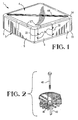
- FIGURE 1 is a perspective view of an outlet, the parts of which are assembled together;
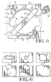
- FIGURE 2 is a fragmentary view of a cover of the outlet and a fastener;
- FIGURE 3 is a perspective view of the outlet shown in Figure 1 with the parts exploded apart from one another;
- FIGURE 4 is a plan view of the base;
- FIGURE 5 is a fragmentary plan view of the base with a data cable received by the base;
- FIGURE 6 is a plan view of multiple, interchangeable plates of the outlet;
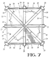
- FIGURE 7 is a plan view of the cover inverted;
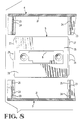
- FIGURE 8 is a fragmentary view of a portion of the base and cover cut away, and receiving one of the plates shown in Figure 6;
- FIGURE 9 is a view similar to Figure 8 showing assembled, the base and the cover and the plate;
- FIGURE 10 is a fragmentary perspective view of a portion of the base;
- FIGURE 11 is a fragmentary section view of the base, cover and plate as shown in Figure 9;
- FIGURE 12 is a view similar to Figure 11, showing the base, cover and plate assembled together; and
- FIGURE 13 is a view similar to Figure 12, showing the plate assembled incorrectly to the base, and preventing assembly of the cover with the base.
- With reference to Figures 1 and 3, an outlet 1 for communications cable comprises an
enclosure 2 covered by and defined by abase 3 and a cover 4 andmultiple plates 5, Figures 1, 3 and 6. Thebase 3 and the cover 4 are constructed such that the horizontal surfaces are exposed on both, top and bottom sides, so as to be capable of being molded between straight draw molding dies, not shown. The vertical surfaces of thebase 3 and the cover 4 are straight, so as to be capable of being molded by straight draw molding dies. Theplates 5 shown in Figure 1 are each blank, without an opening. Theplates 5 of Figure 6 are provided withconnector receiving openings 6 constructed with various connector receiving shapes adapted to receive respective electrical data connectors, not shown, of different shapes and sizes. The data connectors are of known types for connecting to different electrical and optical communications cables that transmit data rather than electrical power. Such connectors are known, for example, from US-A-4,795,356, requiring a correspondingly shapedopening 6 in one of theplates 5, from US-A-4,884,982, requiring a correspondingly shapedopening 6 in one of theplates 5, from U-S-A-4,659,166, disclosing multiple connectors, two of which can be received inmultiple openings 6 in one of theplates 5.Other plates 5 are adapted withopenings 6 for receiving other connectors, not shown. - With reference to Figures 3, 4 and 5, the
base 3 is of unitary, one piece, construction, molded from plastics material. Abottom 7 of thebase 3 has an enlarged, circular, cable receiving opening 8 intersected by smaller,rectangular openings 9. Thebottom 7 provides an exterior mounting surface adapted for attachment to a floor, or wall box or plaster ring, or an item of furniture, not shown. Thebase 3 is provided withapertures 10, Figure 4, encircled by reinforcingbosses 11, and through whichfasteners 12, Figure 5, can project for attaching thebase 3. A knock outplate 13, Figure 4, is defined by segmentedslits 14 through thebottom 7 separated from one another by thin webs. The webs are frangible, whereby the knock outplate 13 is removable to create a cable receiving opening for placement against an item of furniture. One of theslits 14 is wide enough to receive a prying tool, not shown, such as the shank of a screwdriver, to pry the knock outplate 13 and break the webs. - A raised reinforcing rib encircling the cable receiving opening 8 projects into the
enclosure 2 and defines aspindle 15 of abobbin 16, Figure 5, for winding acommunications cable 17 emerging from a floor or an item of furniture and received in CLrectangular opening 9, both therectangular openings 9 extending through thespindle 15 and communicating with thecable receiving opening 8. Segmentedflanges 18 of thebobbin 16 overlap thespindle 15. Theflanges 18 are spaced from thebottom 7 of thebase 3 and are oppositecorresponding openings 19 through thebottom 7 shaped like the edges of theflanges 18. Theopenings 19 in the bottom are aligned with theflanges 18, through whichopenings 19 are inserted mold core pins, not shown, for forming theflanges 18 integral with thespindle 15 during a plastics molding operation. Thecable 17 connected with anelectrical data connector 20, Figure 5, emerging from the floor or from an item of furniture, is received by thecable receiving opening 8, and is wound part way around thespindle 15, with thecable 17 in registration with therectangular opening 9. Theflanges 18 overlap thecable 17 on thespindle 15. Further details of theconnector 20 are disclosed in US-A-4,795,356. - According to an advantage of the invention, the
multiple plates 5 are interchangeable. Each of theplates 5 is removable for replacement by one of theplates 5 having a selectedconnector receiving opening 6, for example, the opening 6 of Figures 8 and 9 adapted to receive thedata connector 20 connected to thecable 17. - The
plates 5 are adapted for receipt inplate receiving openings 21, Figures 3 and 8, that are partly in thebase 3 and partly in the cover 4. Each of theplate receiving openings 21 are open along aparting line 22, Figure 9, where thebase 3 and cover 4 meet in abutment. Theparting line 22 dividescolumns 23 of theenclosure 2. Thedivided columns 23, in part, are integral with thebase 3 and, in part, are integral with the cover 4. Thecolumns 23, Figures 4, 7 and 10, are hollow and constructed of thin, straight walls adapted for fabrication by molding as a unitary one piece cover. Thecolumns 23 are spaced apart from one another and define sides of theplate receiving openings 21. Thecolumns 23 further define sides of theenclosure 2 extending upwardly from thebottom 7. Thecolumns 23 separate theplate receiving openings 21. Thecolumns 23 on the cover 4 are stacked on thecolumns 23 of thebase 3.Grooves 24, Figure 8, 9 and 10, at the sides of theenclosure 2, extend along thecolumns 23 in both thebase 3 and the cover 4. In thebase 3 only, detents 25, Figure 8, are recessed in bottoms of thegrooves 24. Projectingportions 26 offlanges 27, Figures 8 and 9, adapt theplates 5, and more specifically theflanges 27 along sides of theplates 5, for frictional interlocking with thedetents 25, Figure 9, when thegrooves 24 receive corresponding sides of theplates 5. Thedetents 25 are relatively near theparting line 22, such that theplates 5 are nearly fully inserted along theplate receiving openings 21 before interlocking with thebase 3. Thereby, undesired interlocking is avoided until theplates 5 are fully inserted. Theplates 5 are readily removed by sliding theplates 5 along thegrooves 24 with sufficient force to overcome the frictional interlocking. Theplates 5 are removably retained, by being interlocked with thebase 3. - The
plates 5 are adapted to be mounted upside down, if desired. With reference to Figures 8 and 9, two projectingportions 26 are distributed, evenly spaced, across a midpoint of each of the sides of theplates 5. Theparting line 22 intersects the midpoint. One of theprojections 26 in each side of theplates 5 will interlock with acorresponding detent 25 when theplates 5 are mounted in corresponding positions, as shown in Figure 9, or upside down relative to that, as shown in Figure 9. - The
columns 23 of the cover 4 are comprised ofrecesses 28 in bottoms of thegrooves 24. Therecesses 28 face theflanges 27 of theplates 5. Therecess 28 provide clearances, Figure 9, allowing passage of theprojections 26 on theflanges 27 of theplates 5 without interlocking with the cover 4. The cover 4 can be mounted to thebase 3 after all theplate receiving openings 21 are filled with interlockedplates 5 without dislodging the interlockedplates 5. Top ends of theplates 5 along the sides of theenclosure 2 define an open top of theenclosure 2. Further, the cover 4 can be removed without dislodging the interlockedplates 5 that will remain interlocked with thebase 3. Replacement of theplates 5 is easily accomplished, when removal of the cover 4 will expose the contents of theenclosure 2 with theplates 5 in place on thebase 3. - With reference to Figures 4, 7 and 10, top and bottom ends of the
plate receiving openings 21 are defined by spaced apart, inner and outer, reinforcingribs base 3, Figure 4, and similarly in the cover 4, Figure 7. The cover 4 is of unitary one piece construction, molded from plastics material. The cover 4, Figure 7, has a series of raised reinforcing ribs 30' joined to theinner rib 29 and extending from eachcolumn 23 to the center of the cover 4 where the reinforcing ribs 30' intersect one another. - The
inner rib 29 of the cover 4, Figure 7, encircles the periphery of theenclosure 2. Theinner rib 29 of thebase 3, Figure 4, encircles the periphery of theenclosure 2 and is cross braced and joined at corners of the periphery by curved reinforcingribs 31 defining an outer spindle for confining a wound communications cable. Theouter ribs 30 span betweencolumns 23, joining thecolumns 23 at thegrooves 24. -
Elongated channels 32, Figures 11 and 12, extend along opposite ends of theplates 5 and receive the outer reinforcingribs 30 of thebase 3 and of the cover 4, theflanges 27 of theplates 5 being slidable along thegrooves 24 of thebase 3 until thechannels 32 receive theouter rib 30 of thebase 3. Theplates 5 interlock with thedetents 25 to retain theplates 5. When the cover 4 is installed over theenclosure 2, theplates 5 are slidable along thegrooves 24 of the cover 4 until thechannels 32 receive theouter rib 30 of the cover 4. The cover 4 overlaps theplates 5 and prevents removal of theplates 5. - With reference to Figures 10 -13, the
ribs 30 of thebase 3 extend from aledge 33 extending around the periphery of theenclosure 2 and extending in an overhang beyond the mounting surface provided by thebottom 7. Therib 30 is on theledge 33. Achamfer 34, Figures 11-13, is along an exterior underside of theledge 33. - A similar but oppositely
inclined chamfer 34 of the cover 4, Figures 3 and 11, is along an exterior periphery of the cover 4 and intersects theplate receiving openings 21. Theplates 5 each haveexterior bezels 35, Figures 11-13, adapted for receipt in theplate receiving openings 21 of the cover 4. At the ends of theplates 5, top and bottom ends 36 of thebezels 35 overlap thechannels 32 of theplates 5 and extend outwardly, top and bottom, beyond thechannels 32 to fill theplate receiving openings 21 of thebase 3 and of the cover 4. At the sides of theplates 5, the bezels 35 bridge between thecolumns 23 to fill theplate receiving openings 21. Thebezels 35 are adapted to be flush with the sides of theenclosure 2. At the sides of the plates, theflanges 27 of theplates 5 extend outwardly beyond thebezels 35, Figure 8, to register inrespective grooves 24 of thecolumns 23. Theflanges 27 are inward behind thebezels 35 to be hidden when thebezels 35 fill theplate receiving openings 21. The ends 36 of the bezels are received incut outs 37, Figure 1, in therespective chamfers 34 of the cover 4 and of thebase 3. The ends 36 of the bezels have chamfers flush with thechamfers 34 of the cover 4 and of thebase 3. - The
plates 5 comprise a feature that prevents installation of theplates 5 inside out in theplate receiving openings 21, Figure 13. When one of theplates 5, for example, is installed inside out, as shown in Figure 13, oneend 36 of the bezel impinges against theinner rib 29 of thebase 3. Theinner rib 29 is taller than theouter rib 30 and resists movement of theplate 5 far enough to interlock theprojections 26 of theflanges 27 with thedetents 25. Similarly, the projectingend 36 of thebezel 35 impinges against the tallerinner rib 29 of the cover 4 to resist complete insertion of theplate 5 along theplate receiving opening 21 of the cover 4 and to prevent the cover 4 from meeting thebase 3 along theparting line 22, Figure 13. - The
columns 23 of theenclosure 2 are beveled flush with therespective chamfers 34 of the cover 4 and of thebase 3. Eachcolumn 23 at a corner of theenclosure 2 is convex and provides a corresponding curve in the sides of theenclosure 2. Eachcolumn 23 at a corner is smoothly beveled, following along the curve, flush with thechamfers 34, and is also smoothly curved around the corners of the cover 4 and of thebase 3. - The
spindle 15, Figures 3 and 5, is braced by achannel 38 that bridges theopening 8. Thebase 3 has an integral, hollow mountingpost 39 that is integral with thechannel 38 and that projects outwardly from thechannel 38 and from theenclosure 2 toward the cover 4. - A portion of the
post 39 is cut away to provide an elongated, recessedkeyway 40 along the mountingpost 39. The cover 4, Figure 2, has a central projecting, hollow hub 41 from which projects anelongated key 42 for receipt along thekeyway 40 to orient the cover 4 with thebase 3. The hub 41 is slit partially through to provide segmented spring, gripping fingers that encircle and grip the shank of anelongated fastener 43 used to secure the cover 4 to the mountingpost 39, and thefastener 43 slidably extends in the hub 41 and in the mountingpost 39. Thefastener 43 can extend through the mountingpost 39 and threadably secure to an internally threaded nut, not shown, on the exterior of thebottom 7. Alternatively, thefastener 43 can be of a size to self tap into the mountingpost 39. To remove the cover 4 from theenclosure 2, thefastener 43 is loosened and is withdrawn partially from the mountingpost 39. Since the hub 41 grips thefastener 43, thefastener 43 can be used as a handle, whereby an upward pull on thefastener 43 will remove the cover 4 from theenclosure 2 without dislodging theplates 5. - The cover 4, Figure 3, has an
external stripe 44 of thickened material in which anelongated recess 45 is located so as to intersect the hollow hub 41. The hollow hub 41 has acounterbore 46 in the recess to countersink an enlarged head of thefastener 43. Alabel 47 fits in therecess 45 to hide thefastener 43 and camouflage the ease of entry into the enclosure 1. Thelabel 47 is covered by a transparentplastics window pane 48 havingend flanges 49 that clip to sides of therecess 45.
Claims (1)
- An outlet (1) for communications cable (17),comprising an enclosure (2) defined by a base (3), multiple sides, a cover (4) for covering the enclosure (2), and a cable receiving opening (8) in the base (3), characterised by multiple interchangeable plates (5) mountable along-the sides (23) of the enclosure (2), each of the plates (5) being removable for replacement by one of the plates (5) having a connector receiving opening (6) adapted to receive a data connector (20) terminated to a cable (17) received by the cable receiving opening (8).
Applications Claiming Priority (2)
| Application Number | Priority Date | Filing Date | Title |
|---|---|---|---|
| US07/830,102 US5276279A (en) | 1992-02-03 | 1992-02-03 | Surface mount outlet |
| US830102 | 1992-02-03 |
Publications (3)
| Publication Number | Publication Date |
|---|---|
| EP0554986A2 EP0554986A2 (en) | 1993-08-11 |
| EP0554986A3 EP0554986A3 (en) | 1994-03-23 |
| EP0554986B1 true EP0554986B1 (en) | 1996-07-24 |
Family
ID=25256317
Family Applications (1)
| Application Number | Title | Priority Date | Filing Date |
|---|---|---|---|
| EP93300400A Expired - Lifetime EP0554986B1 (en) | 1992-02-03 | 1993-01-21 | Surface mount outlet |
Country Status (4)
| Country | Link |
|---|---|
| US (1) | US5276279A (en) |
| EP (1) | EP0554986B1 (en) |
| JP (1) | JPH05260627A (en) |
| DE (1) | DE69303734T2 (en) |
Cited By (9)
| Publication number | Priority date | Publication date | Assignee | Title |
|---|---|---|---|---|
| US8257302B2 (en) | 2005-05-10 | 2012-09-04 | Corindus, Inc. | User interface for remote control catheterization |
| US8480618B2 (en) | 2008-05-06 | 2013-07-09 | Corindus Inc. | Catheter system |
| US8600477B2 (en) | 2004-08-16 | 2013-12-03 | Corinduc, Inc. | Image-guided navigation for catheter-based interventions |
| US8694157B2 (en) | 2008-08-29 | 2014-04-08 | Corindus, Inc. | Catheter control system and graphical user interface |
| US8790297B2 (en) | 2009-03-18 | 2014-07-29 | Corindus, Inc. | Remote catheter system with steerable catheter |
| US9220568B2 (en) | 2009-10-12 | 2015-12-29 | Corindus Inc. | Catheter system with percutaneous device movement algorithm |
| US9545497B2 (en) | 2008-12-12 | 2017-01-17 | Corindus, Inc. | Remote catheter procedure system |
| US11696808B2 (en) | 2009-10-12 | 2023-07-11 | Corindus, Inc. | System and method for navigating a guide wire |
| US11918314B2 (en) | 2009-10-12 | 2024-03-05 | Corindus, Inc. | System and method for navigating a guide wire |
Families Citing this family (27)
| Publication number | Priority date | Publication date | Assignee | Title |
|---|---|---|---|---|
| US5668654A (en) * | 1995-05-30 | 1997-09-16 | The Whitaker Corporation | Package for an infrared communications adapter |
| US5679924A (en) * | 1995-06-07 | 1997-10-21 | Walker Systems, Inc. | Non-metallic floor box |
| US5804765A (en) * | 1996-05-23 | 1998-09-08 | The Siemon Company | Cable management enclosure |
| AU720876B2 (en) * | 1996-06-14 | 2000-06-15 | Lucent Technologies Inc. | Signal transmission media routing arrangement |
| US5886298A (en) * | 1996-09-09 | 1999-03-23 | Lucent Technologies Inc. | Apparatus for mounting cables |
| US5770817A (en) * | 1996-09-20 | 1998-06-23 | Lo; Jeffrey C. P. | Raceway box with replaceable cable and connector receptacles |
| US5783774A (en) * | 1996-10-21 | 1998-07-21 | Walker Systems, Inc. | Non-metallic floor box |
| US6132242A (en) * | 1997-01-08 | 2000-10-17 | The Whitaker Corporation | Distribution device for wiring |
| US6074247A (en) * | 1997-01-08 | 2000-06-13 | The Whitaker Corporation | Lan distribution module |
| US6191356B1 (en) * | 1998-03-13 | 2001-02-20 | Avaya Inc. | Reduced condensation protector panel for use in a building entrance protector box |
| US6037540A (en) * | 1998-03-16 | 2000-03-14 | Lucent Technologies Inc. | Blank panel with integrated physical cover and mounting arrangement for a RJ 21 connector |
| US6107568A (en) * | 1998-03-19 | 2000-08-22 | Hubbell Incorporated | Electrical box and holding device for use therewith |
| US6081180A (en) * | 1998-09-22 | 2000-06-27 | Power Trends, Inc. | Toroid coil holder with removable top |
| FR2787250B1 (en) * | 1998-12-09 | 2001-02-23 | Rehau Sa | UNIVERSAL JUNCTION BOX FOR MOLDINGS OR CHUINS FOR ELECTRICAL DISTRIBUTION |
| US7456355B2 (en) | 2004-03-10 | 2008-11-25 | G4S Justice Services (Canada) Inc. | Permanently closed enclosure apparatus and method for accessing an internal portion thereof |
| US6969800B1 (en) * | 2004-08-11 | 2005-11-29 | Hsueh-Shu Liao | Hub concealed by tabletop |
| US7893362B2 (en) * | 2006-06-28 | 2011-02-22 | Commscope, Inc. Of North Carolina | Smoke-resistant surface mount box for plenum space |
| US8901417B2 (en) * | 2007-05-11 | 2014-12-02 | Hubbell Incorporated | Network enclosure with removable and interchangeable sides |
| US9833293B2 (en) | 2010-09-17 | 2017-12-05 | Corindus, Inc. | Robotic catheter system |
| US9134496B2 (en) * | 2011-05-19 | 2015-09-15 | Communication Systems, Inc. | Modular plug and play connectivity platform |
| CA2888023C (en) | 2014-04-15 | 2019-09-24 | Norman R. Byrne | Rotatable power center for a work surface |
| US9398710B2 (en) * | 2014-08-07 | 2016-07-19 | Continental Automotive Gmbh | Enclosure for an electronic control unit and electronic control unit |
| US9472932B2 (en) * | 2014-10-24 | 2016-10-18 | S.J. Electro Systems, Inc. | Electrical enclosure cord stowage system |
| US10666033B2 (en) * | 2016-05-11 | 2020-05-26 | Suttle, Inc. | Modular stackable enclosure system |
| JP6462648B2 (en) * | 2016-12-02 | 2019-01-30 | 矢崎総業株式会社 | Electrical junction box |
| US10673218B2 (en) * | 2017-08-17 | 2020-06-02 | Thomas & Betts International Llc | Molded electrical junction box |
| US11466897B2 (en) * | 2017-11-22 | 2022-10-11 | Gary FRATIANNE | Convertible end cap and baseboard heater cover assembly |
Family Cites Families (6)
| Publication number | Priority date | Publication date | Assignee | Title |
|---|---|---|---|---|
| DE2116401C3 (en) * | 1971-04-03 | 1980-07-10 | Siemens Ag | Floor connection device for electrical underfloor installations |
| DE2116402C3 (en) * | 1971-04-03 | 1979-03-01 | Siemens Ag | Floor connection device for electrical underfloor installations |
| US3877601A (en) * | 1973-03-12 | 1975-04-15 | Textron Inc | Floor box |
| US4659166A (en) * | 1985-11-12 | 1987-04-21 | Amp Incorporated | Connector for multiple coaxial cables |
| US4795356A (en) * | 1987-01-20 | 1989-01-03 | Amp Incorporated | Electrical tap connector assembly |
| US4884982A (en) * | 1989-04-03 | 1989-12-05 | Amp Incorporated | Capacitive coupled connector |
-
1992
- 1992-02-03 US US07/830,102 patent/US5276279A/en not_active Expired - Lifetime
-
1993
- 1993-01-21 DE DE69303734T patent/DE69303734T2/en not_active Expired - Fee Related
- 1993-01-21 EP EP93300400A patent/EP0554986B1/en not_active Expired - Lifetime
- 1993-02-03 JP JP5016436A patent/JPH05260627A/en not_active Withdrawn
Cited By (15)
| Publication number | Priority date | Publication date | Assignee | Title |
|---|---|---|---|---|
| US8600477B2 (en) | 2004-08-16 | 2013-12-03 | Corinduc, Inc. | Image-guided navigation for catheter-based interventions |
| US8257302B2 (en) | 2005-05-10 | 2012-09-04 | Corindus, Inc. | User interface for remote control catheterization |
| US9402977B2 (en) | 2008-05-06 | 2016-08-02 | Corindus Inc. | Catheter system |
| US8828021B2 (en) | 2008-05-06 | 2014-09-09 | Corindus, Inc. | Catheter system |
| US9095681B2 (en) | 2008-05-06 | 2015-08-04 | Corindus Inc. | Catheter system |
| US9168356B2 (en) | 2008-05-06 | 2015-10-27 | Corindus Inc. | Robotic catheter system |
| US8480618B2 (en) | 2008-05-06 | 2013-07-09 | Corindus Inc. | Catheter system |
| US10987491B2 (en) | 2008-05-06 | 2021-04-27 | Corindus, Inc. | Robotic catheter system |
| US8694157B2 (en) | 2008-08-29 | 2014-04-08 | Corindus, Inc. | Catheter control system and graphical user interface |
| US9545497B2 (en) | 2008-12-12 | 2017-01-17 | Corindus, Inc. | Remote catheter procedure system |
| US10561821B2 (en) | 2008-12-12 | 2020-02-18 | Corindus, Inc. | Remote catheter procedure system |
| US8790297B2 (en) | 2009-03-18 | 2014-07-29 | Corindus, Inc. | Remote catheter system with steerable catheter |
| US9220568B2 (en) | 2009-10-12 | 2015-12-29 | Corindus Inc. | Catheter system with percutaneous device movement algorithm |
| US11696808B2 (en) | 2009-10-12 | 2023-07-11 | Corindus, Inc. | System and method for navigating a guide wire |
| US11918314B2 (en) | 2009-10-12 | 2024-03-05 | Corindus, Inc. | System and method for navigating a guide wire |
Also Published As
| Publication number | Publication date |
|---|---|
| DE69303734T2 (en) | 1997-03-06 |
| EP0554986A3 (en) | 1994-03-23 |
| US5276279A (en) | 1994-01-04 |
| EP0554986A2 (en) | 1993-08-11 |
| JPH05260627A (en) | 1993-10-08 |
| DE69303734D1 (en) | 1996-08-29 |
Similar Documents
| Publication | Publication Date | Title |
|---|---|---|
| EP0554986B1 (en) | Surface mount outlet | |
| US6723922B1 (en) | Universal cover plate | |
| US7282643B2 (en) | Weatherproof receptacle cover with adapter plate | |
| US6987225B2 (en) | Convertible electrical device cover and method for installing same | |
| US7763798B1 (en) | Convertible electrical device cover and method for installing same | |
| US6441307B1 (en) | Universal cover plate | |
| US4449015A (en) | Connector cover with multiple mounting means | |
| US7186915B2 (en) | Mud box and adapters | |
| US5645449A (en) | Low profile mixed media information outlet | |
| US7563978B2 (en) | Electrical box for concrete walls | |
| AU599769B2 (en) | Two-piece face plate for wall box mounted device | |
| US6616005B1 (en) | Modular faceplate assembly for an electrical box | |
| EP1442506B1 (en) | Electrical box with recessed faceplate | |
| US7348486B1 (en) | Convertible electrical device cover and method for installing same | |
| US4850901A (en) | Communications outlet | |
| US7345238B1 (en) | Universal cover plate | |
| EP1148604A2 (en) | Electric outlet box | |
| JP2582773Y2 (en) | Fuse box fuse lock structure | |
| US20230034501A1 (en) | Interchangeable Modular Outlet Cover | |
| JP3455943B2 (en) | Wiring outlet for floor panel | |
| JP2000217228A (en) | Multifunctional outlet for wiring | |
| JPH0833160A (en) | Box for burying in concrete | |
| EP2101382B1 (en) | Box for electrical mechanism adaptor | |
| JPH0561850B2 (en) |
Legal Events
| Date | Code | Title | Description |
|---|---|---|---|
| PUAI | Public reference made under article 153(3) epc to a published international application that has entered the european phase |
Free format text: ORIGINAL CODE: 0009012 |
|
| AK | Designated contracting states |
Kind code of ref document: A2 Designated state(s): DE FR GB |
|
| PUAL | Search report despatched |
Free format text: ORIGINAL CODE: 0009013 |
|
| AK | Designated contracting states |
Kind code of ref document: A3 Designated state(s): DE FR GB |
|
| 17P | Request for examination filed |
Effective date: 19940917 |
|
| 17Q | First examination report despatched |
Effective date: 19950619 |
|
| GRAH | Despatch of communication of intention to grant a patent |
Free format text: ORIGINAL CODE: EPIDOS IGRA |
|
| GRAH | Despatch of communication of intention to grant a patent |
Free format text: ORIGINAL CODE: EPIDOS IGRA |
|
| GRAA | (expected) grant |
Free format text: ORIGINAL CODE: 0009210 |
|
| AK | Designated contracting states |
Kind code of ref document: B1 Designated state(s): DE FR GB |
|
| REF | Corresponds to: |
Ref document number: 69303734 Country of ref document: DE Date of ref document: 19960829 |
|
| ET | Fr: translation filed | ||
| PLBE | No opposition filed within time limit |
Free format text: ORIGINAL CODE: 0009261 |
|
| STAA | Information on the status of an ep patent application or granted ep patent |
Free format text: STATUS: NO OPPOSITION FILED WITHIN TIME LIMIT |
|
| 26N | No opposition filed | ||
| PGFP | Annual fee paid to national office [announced via postgrant information from national office to epo] |
Ref country code: GB Payment date: 19981211 Year of fee payment: 7 |
|
| PGFP | Annual fee paid to national office [announced via postgrant information from national office to epo] |
Ref country code: FR Payment date: 19990107 Year of fee payment: 7 |
|
| PGFP | Annual fee paid to national office [announced via postgrant information from national office to epo] |
Ref country code: DE Payment date: 19990228 Year of fee payment: 7 |
|
| PG25 | Lapsed in a contracting state [announced via postgrant information from national office to epo] |
Ref country code: GB Free format text: LAPSE BECAUSE OF NON-PAYMENT OF DUE FEES Effective date: 20000121 |
|
| GBPC | Gb: european patent ceased through non-payment of renewal fee |
Effective date: 20000121 |
|
| PG25 | Lapsed in a contracting state [announced via postgrant information from national office to epo] |
Ref country code: FR Free format text: LAPSE BECAUSE OF NON-PAYMENT OF DUE FEES Effective date: 20000929 |
|
| PG25 | Lapsed in a contracting state [announced via postgrant information from national office to epo] |
Ref country code: DE Free format text: LAPSE BECAUSE OF NON-PAYMENT OF DUE FEES Effective date: 20001101 |
|
| REG | Reference to a national code |
Ref country code: FR Ref legal event code: ST |