EP0556500A1 - Surgical drill guide - Google Patents
Surgical drill guide Download PDFInfo
- Publication number
- EP0556500A1 EP0556500A1 EP92305746A EP92305746A EP0556500A1 EP 0556500 A1 EP0556500 A1 EP 0556500A1 EP 92305746 A EP92305746 A EP 92305746A EP 92305746 A EP92305746 A EP 92305746A EP 0556500 A1 EP0556500 A1 EP 0556500A1
- Authority
- EP
- European Patent Office
- Prior art keywords
- collet
- handle
- lobes
- cylindrical portion
- bore
- Prior art date
- Legal status (The legal status is an assumption and is not a legal conclusion. Google has not performed a legal analysis and makes no representation as to the accuracy of the status listed.)
- Withdrawn
Links
Images


Classifications
-
- A—HUMAN NECESSITIES
- A61—MEDICAL OR VETERINARY SCIENCE; HYGIENE
- A61B—DIAGNOSIS; SURGERY; IDENTIFICATION
- A61B17/00—Surgical instruments, devices or methods, e.g. tourniquets
- A61B17/16—Bone cutting, breaking or removal means other than saws, e.g. Osteoclasts; Drills or chisels for bones; Trepans
- A61B17/17—Guides or aligning means for drills, mills, pins or wires
- A61B17/1714—Guides or aligning means for drills, mills, pins or wires for applying tendons or ligaments
Definitions
- This invention relates generally to surgical instruments and, in particular, to surgical instruments having a plurality of components that are able to be locked together to produce a fixed structure.
- the invention concerns a drill guide in which a cylindrical tube is slidable relative to a handle and is able to be locked to the handle in a selected position.
- Drill guides are often used in surgical procedures in order to facilitate "blind” drilling by properly placing a drill relative to adjacent anatomical structures.
- a drill guide generally has a handle for holding the guide exterior to the body, a probe tip to be placed within the body at a point where one end of a drilled hole is desired and a tube which has its axis aligned to intersect the probe tip and which is slidable relative to the handle so that the distance between the end of the tube and the probe tip is variable.
- Drill guides are normally used in arthroscopic procedures by placing the probe tip through an arthroscopic portal, placing the tube end against a bone surface, inserting a drill into the tube and drilling through the bone until the drill comes out adjacent the probe tip.
- U.S. Patent 4,739,751 (Sapega et al.).
- This device includes a handle portion having a curved probe tip which is placeable at a specific location and a cylindrical drill guide attached to an arm slidable along the handle.
- the axis of the cylindrical drill guide intersects with the tip of the curved probe such that when the probe is placed within a joint during an arthroscopic procedure the placement of the cylindrical drill guide on the exterior surface of the bone enables a drill passing through the guide to intersect with the probe tip.
- Movement of the drill guide relative to the probe tip is a common feature of drill guides and is necessary to vary the distance between these two components to accommodate different bone thicknesses.
- Sapega et al. disclose that the drill guide arm may be attached to the handle by a ratchet and pawl mechanism to provide stability during drilling.
- U.S. Patent 4,708,139 discloses a similar arthroscopic drill guide which varies from Sapega et al. essentially in the means by which the drill guide arm is secured to the handle.
- Dunbar, IV shows a threaded knob passing through the handle and the drill guide arm. Rotation of the knob in one direction locks the guide arm on the handle and rotation in the other direction allows the guide arm to slide along the handle.
- U.S. Patent 4,920,958 discloses yet another drill guide assembly wherein the drill guide tube is locked to one end of an arcuate handle by a U-shaped spring.
- the drill guide tube is able to be pushed towards the probe tip without releasing the locking mechanism but is not able to be withdrawn without depressing the two legs of the U-shaped clip together.
- the precise tibial guide has a handle to which a probe tip and a drill guide arm are fixedly attached.
- the drill guide arm has a threaded aperture at its end and the drill guide is threadably secured in this aperture in alignment with the probe tip.
- a trigger mechanism on the handle releases the threads momentarily to enable the drill guide to be moved quickly longitudinally without rotation. Releasing the trigger engages the threads of the drill guide with threads in the end of the drill guide arm such that continued movement of the drill guide is only possible by rotation.
- a preferred embodiment of the invention hereinafter described in detail with reference to the drawings provides a drill guide in which (a) the guide tube is easily engageable with the handle when desired, but relatively immovable with respect to the handle when in the locked mode, (b) the guide tube is relatively locked against movement in either direction relative to the handle unless the locking mechanism is positively released by the user, and (c) the locking mechanism by which the guide tube is locked to the handle is easily operable when depressed by a user's thumb.
- a surgical instrument having a locking device for locking component parts of the instrument together, the surgical instrument comprising a handle and an elongated cylindrical portion longitudinally slidable within a cylindrical bore of the handle.
- a split collet having a tapered external surface surrounds the cylindrical portion and is interposed between it and a correspondingly tapered internal surface of the bore.
- the collet is adapted to be longitudinally movable to a position where its tapered surface is engaged by the tapered surface of the bore.
- a trigger attached to the collet and the handle is operable by a user's thumb to move the collet distally, out of engagement with the bore internal surface, or proximally, into engagement.
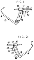
- Figure 1 is an elevational view of a preferred embodiment of the invention in the form of a tibial drill guide.
- Figure 2 is a rear elevational view of the tibial drill guide shown in Figure 1.
- Figure 3 is an exploded view of a portion of Figure 1.
- Figure 4 is a right side elevational view of Figure 3.
- Figure 5 is a side elevational view of a leaf spring forming a part of this invention.
- Figure 6 is a right side elevational view of Figure 5.
- Figure 7 is a side elevational view of a split collet forming part of this invention.
- Figure 8 is a left end view of Figure 7.
- Figure 9 is a right end view of Figure 7.
- Figure 10 is a side elevational view of the spring lever forming a part of this invention.
- Figure 11 is a left end view of Figure 10.
- Figure 12 is a diagrammatic view of the relationship of parts of the invention in the locked mode.
- Figure 13 is a diagrammatic view of the relationship of parts of the invention in the unlocked mode.
- FIG 1 there is shown an elevational view of a tibial drill guide 10 having a handle 12, a probe member 14 and a cylindrical drill guide tube 16.
- the axis of guide tube 16 is aligned with the tip 17 of probe member 14.
- the rear elevational view of tibial guide 10 is shown in Figure 2 wherein it may be clearly seen that probe member 14 has an arcuate arm 18 which fits slidably within arcuate slot 20 formed in handle 12.
- Locking knob 22 secures probe member 14 to handle 12 in a conventional manner.
- the upper end of handle 12 is formed into a cylindrical housing 30 having a tapered interior channel (best seen in Figures 12 and 13) within which is received a split collet 32 (best in Figures 7, 8 and 9).
- Cylindrical tube 16 is sized to be received and axially aligned within collet 32 (in its uncompressed state) and housing 30.
- collet 32 is longitudinally movable within the interior channel 31 of housing 30 from a locked position in which collet 32 is at its proximal-most position relative to housing 30 (best seen in Figure 12) and an unlocked position in which collet 32 is at its distal-most position relative to housing 30 (best seen in Figure 13).
- cruciate trigger mechanism 40 which comprises a leaf spring 42 (best seen in Figures 5 and 6) and a thumb lever 44 (best seen in Figures 1, 10 and 11).
- the lower end 46 of leaf spring 42 is fixedly secured to handle 12 and the upper end 48 is secured within a receiving channel 50 formed in the head 60 of collet 32 (best seen in Figures 3 and 7).
- collet 32 is normally free to move longitudinally within the internal bore 31 of housing 30 and, by making spring 42 normally biased proximally (i.e. to the right as viewed in Figure 1) the collet is normally biased proximally as well.
- Leaf spring 42 has a relatively wide end 48 (best seen in Figures 4 and 6) in order to conform the shape of end 48 to the relatively rectangular shape of channel 50.
- Leaf spring 42 includes an aperture 52 near end 48, aperture 52 serving to receive thumb lever 44 therethrough.
- Thumb lever 44 is hingedly connected at 54 to handle 12 and has a relatively wide thumb contacting arm 56, the upper end of which is joined to a relatively narrow hinge arm 58.
- Arm 56 has a pair of shoulders 57a and 57b adjacent hinge arm 58 and the interaction of the shoulders with the edges of aperture 52 serves to move leaf spring 42 distally as thumb lever 44 is depressed, thus causing end 48 and collet 32 to move distally.
- Releasing pressure on thumb lever 44 allows the natural bias of spring 42 to move itself and associated parts proximally. It will be understood that the shape of either spring 42 or lever 44 may change depending on the structure of handle 12.
- Collet 32 has four longitudinally extending fingers or lobes 62a, b, c and d, each of which is arcuately shaped. Three identical channels 64a, b and c separate some of the lobes as shown, and a top channel 65 extends the length of collet 32. As best seen in Figures 12 and 13, movement of collet 32 to its proximal-most position relative to housing 30 causes the tapered interior of bore 31 to squeeze the lobes inwardly to frictionally engage tube 16. Movement of collet 32 to its distal-most position relaxes the radially inward pressure and allows the natural resiliency of the lobes to permit tube 16 to slide in either direction.
Abstract
A drill guide (10) is disclosed in which a cylindrical guide tube (16) is secured to a handle (12) so that it may not be easily longitudinally moved in either direction without the user engaging a thumb activated locking mechanism. The cylindrical guide tube passes through a conically tapered cylindrical bore (31) within the drill guide handle and a similarly tapered split collet (32) is interposed concentrically between the exterior of the cylindrical guide tube and the interior of the bore. The collet is provided with a plurality of longitudinally extending lobes which are sufficiently resilient that movement of the collet to its proximal-most position causes the lobes to squeeze inwardly against the cylindrical guide tube. Frictional engagement between the collet lobes and the guide tube prevents the latter from moving until the collet is moved distally to release pressure on the lobes. The collet is normally biased proximally by a leaf spring (42,48) attached to the drill guide handle and a thumb activated lever (40) is provided to move the leaf spring distally to release pressure on the lobes and unlock the cylindrical guide tube.
Description
- This invention relates generally to surgical instruments and, in particular, to surgical instruments having a plurality of components that are able to be locked together to produce a fixed structure. In its preferred form, the invention concerns a drill guide in which a cylindrical tube is slidable relative to a handle and is able to be locked to the handle in a selected position.
- Drill guides are often used in surgical procedures in order to facilitate "blind" drilling by properly placing a drill relative to adjacent anatomical structures. A drill guide generally has a handle for holding the guide exterior to the body, a probe tip to be placed within the body at a point where one end of a drilled hole is desired and a tube which has its axis aligned to intersect the probe tip and which is slidable relative to the handle so that the distance between the end of the tube and the probe tip is variable. Drill guides are normally used in arthroscopic procedures by placing the probe tip through an arthroscopic portal, placing the tube end against a bone surface, inserting a drill into the tube and drilling through the bone until the drill comes out adjacent the probe tip.
- One example of a prior art drill guide is shown in U.S. Patent 4,739,751 (Sapega et al.). This device includes a handle portion having a curved probe tip which is placeable at a specific location and a cylindrical drill guide attached to an arm slidable along the handle. The axis of the cylindrical drill guide intersects with the tip of the curved probe such that when the probe is placed within a joint during an arthroscopic procedure the placement of the cylindrical drill guide on the exterior surface of the bone enables a drill passing through the guide to intersect with the probe tip. Movement of the drill guide relative to the probe tip is a common feature of drill guides and is necessary to vary the distance between these two components to accommodate different bone thicknesses. Sapega et al. disclose that the drill guide arm may be attached to the handle by a ratchet and pawl mechanism to provide stability during drilling.
- U.S. Patent 4,708,139 (Dunbar, IV) discloses a similar arthroscopic drill guide which varies from Sapega et al. essentially in the means by which the drill guide arm is secured to the handle. Dunbar, IV shows a threaded knob passing through the handle and the drill guide arm. Rotation of the knob in one direction locks the guide arm on the handle and rotation in the other direction allows the guide arm to slide along the handle.
- U.S. Patent 4,920,958 (Walt et al.) discloses yet another drill guide assembly wherein the drill guide tube is locked to one end of an arcuate handle by a U-shaped spring. The drill guide tube is able to be pushed towards the probe tip without releasing the locking mechanism but is not able to be withdrawn without depressing the two legs of the U-shaped clip together.
- Yet another known drill guide is manufactured by the assignee of the present invention and is part of the Concept Precise ACL Guide system. The precise tibial guide has a handle to which a probe tip and a drill guide arm are fixedly attached. The drill guide arm has a threaded aperture at its end and the drill guide is threadably secured in this aperture in alignment with the probe tip. A trigger mechanism on the handle releases the threads momentarily to enable the drill guide to be moved quickly longitudinally without rotation. Releasing the trigger engages the threads of the drill guide with threads in the end of the drill guide arm such that continued movement of the drill guide is only possible by rotation.
- It has been found that all of the foregoing devices have features which could be improved upon. Most significantly, it has been found desirable to have a drill guide with an easier, single handed operating mechanism for releasing the guide tube to enable it to be moved longitudinally. It has also been found that, once the tube is in place, it is desirable to have a more secure holding device which prevents longitudinal movement of the tube.
- A preferred embodiment of the invention hereinafter described in detail with reference to the drawings provides a drill guide in which (a) the guide tube is easily engageable with the handle when desired, but relatively immovable with respect to the handle when in the locked mode, (b) the guide tube is relatively locked against movement in either direction relative to the handle unless the locking mechanism is positively released by the user, and (c) the locking mechanism by which the guide tube is locked to the handle is easily operable when depressed by a user's thumb.
- More specifically the preferred embodiment described herein is a surgical instrument having a locking device for locking component parts of the instrument together, the surgical instrument comprising a handle and an elongated cylindrical portion longitudinally slidable within a cylindrical bore of the handle. A split collet having a tapered external surface surrounds the cylindrical portion and is interposed between it and a correspondingly tapered internal surface of the bore. The collet is adapted to be longitudinally movable to a position where its tapered surface is engaged by the tapered surface of the bore. A trigger attached to the collet and the handle is operable by a user's thumb to move the collet distally, out of engagement with the bore internal surface, or proximally, into engagement.
- Various aspects of the invention are hereinafter set out in the independent claims, the invention extending to the subject matter common to such claims and to the various features set out in the preceding paragraphs of this Summary, taken together or independently.
- A preferred embodiment of the invention will now be described, by way of example, in more detail with reference to the drawings.
- Figure 1 is an elevational view of a preferred embodiment of the invention in the form of a tibial drill guide.
- Figure 2 is a rear elevational view of the tibial drill guide shown in Figure 1.
- Figure 3 is an exploded view of a portion of Figure 1.
- Figure 4 is a right side elevational view of Figure 3.
- Figure 5 is a side elevational view of a leaf spring forming a part of this invention.
- Figure 6 is a right side elevational view of Figure 5.
- Figure 7 is a side elevational view of a split collet forming part of this invention.
- Figure 8 is a left end view of Figure 7.
- Figure 9 is a right end view of Figure 7.
- Figure 10 is a side elevational view of the spring lever forming a part of this invention.
- Figure 11 is a left end view of Figure 10.
- Figure 12 is a diagrammatic view of the relationship of parts of the invention in the locked mode.
- Figure 13 is a diagrammatic view of the relationship of parts of the invention in the unlocked mode.
- Referring now to Figure 1, there is shown an elevational view of a
tibial drill guide 10 having ahandle 12, aprobe member 14 and a cylindricaldrill guide tube 16. The axis ofguide tube 16 is aligned with thetip 17 ofprobe member 14. The rear elevational view oftibial guide 10 is shown in Figure 2 wherein it may be clearly seen thatprobe member 14 has anarcuate arm 18 which fits slidably withinarcuate slot 20 formed inhandle 12. Locking knob 22 securesprobe member 14 to handle 12 in a conventional manner. - As seen in Figures 3 and 4 (in which
guide tube 16 is omitted for clarity), the upper end ofhandle 12 is formed into acylindrical housing 30 having a tapered interior channel (best seen in Figures 12 and 13) within which is received a split collet 32 (best in Figures 7, 8 and 9).Cylindrical tube 16 is sized to be received and axially aligned within collet 32 (in its uncompressed state) and housing 30. As will be better understood below,collet 32 is longitudinally movable within theinterior channel 31 ofhousing 30 from a locked position in whichcollet 32 is at its proximal-most position relative to housing 30 (best seen in Figure 12) and an unlocked position in whichcollet 32 is at its distal-most position relative to housing 30 (best seen in Figure 13). - Movement of
collet 32 relative tohousing 30 is accomplished bycruciate trigger mechanism 40 which comprises a leaf spring 42 (best seen in Figures 5 and 6) and a thumb lever 44 (best seen in Figures 1, 10 and 11). Thelower end 46 ofleaf spring 42 is fixedly secured to handle 12 and theupper end 48 is secured within areceiving channel 50 formed in thehead 60 of collet 32 (best seen in Figures 3 and 7). It will be understood thatcollet 32 is normally free to move longitudinally within theinternal bore 31 ofhousing 30 and, by makingspring 42 normally biased proximally (i.e. to the right as viewed in Figure 1) the collet is normally biased proximally as well.Leaf spring 42 has a relatively wide end 48 (best seen in Figures 4 and 6) in order to conform the shape ofend 48 to the relatively rectangular shape ofchannel 50. -
Leaf spring 42 includes anaperture 52 nearend 48,aperture 52 serving to receivethumb lever 44 therethrough.Thumb lever 44 is hingedly connected at 54 to handle 12 and has a relatively widethumb contacting arm 56, the upper end of which is joined to a relativelynarrow hinge arm 58.Arm 56 has a pair ofshoulders 57a and 57badjacent hinge arm 58 and the interaction of the shoulders with the edges ofaperture 52 serves to moveleaf spring 42 distally asthumb lever 44 is depressed, thus causingend 48 and collet 32 to move distally. Releasing pressure onthumb lever 44 allows the natural bias ofspring 42 to move itself and associated parts proximally. It will be understood that the shape of eitherspring 42 orlever 44 may change depending on the structure ofhandle 12. -
Collet 32 has four longitudinally extending fingers orlobes 62a, b, c and d, each of which is arcuately shaped. Threeidentical channels 64a, b and c separate some of the lobes as shown, and atop channel 65 extends the length ofcollet 32. As best seen in Figures 12 and 13, movement ofcollet 32 to its proximal-most position relative tohousing 30 causes the tapered interior ofbore 31 to squeeze the lobes inwardly to frictionally engagetube 16. Movement ofcollet 32 to its distal-most position relaxes the radially inward pressure and allows the natural resiliency of the lobes to permittube 16 to slide in either direction. - While the preferred embodiment shows the use of a collet with four tapered lobes, other arrangements may be suitable. For example, any number of lobes may be appropriate; non-tapered surfaces may be used if other means are provided to cam the collet lobes inwardly, etc.
- Also, while the invention has been described in terms of a drill guide, it will be understood that other surgical instruments may be adapted to incorporate the principles of the invention.
Claims (7)
- A surgical instrument comprising a handle and an elongated cylindrical portion longitudinally slidable within a cylindrical bore of said handle, said instrument having a locking device for locking component parts of the surgical instrument together, said surgical instrument comprising:
a collet surrounding part of said cylindrical portion and interposed between same and the internal surface of said bore, said collet being longitudinally movable and having at least two longitudinally extending lobes the external surfaces of which form a tapered surface;
a tapered interior surface forming the interior of said bore and being arranged for engagement by said collet tapered surface when said collet is moved proximally; and
a thumb activated trigger means attached to said handle and arranged to move said collet distally into a first, unlocked position wherein said lobes are not in frictional engagement with said cylindrical portion and proximally into a second, locked position wherein said lobes are urged radially inwardly to lock said cylindrical portion relative to said handle. - A surgical instrument according to claim 1 wherein said thumb activated trigger means comprises:
an elongated leaf spring member fixedly secured at one end to said handle and loosely secured at its other end to said collet, said leaf spring normally biassing said collet proximally; and
an elongated thumb activated trigger lever hingedly secured at one end to said handle and having an intermediate portion thereof engageable with said leaf spring, said trigger lever being normally biased proximally by said leaf spring. - A surgical instrument according to claim 1 wherein said thumb activated trigger means comprises:
a cruciate trigger structure having first and second elongated members, said first member crossing and engageable with an intermediate portion of said second member, one end of said first member attached to said handle and the other end attached to said collet, one end of said second member attached to said handle and the other end being free such that movement of said free end toward said one end of said first member causes said collet to move longitudinally. - A surgical instrument comprising a handle and an elongated cylindrical portion longitudinally slidable within a cylindrical bore of said handle, said instrument having a locking device for locking component parts of the surgical instrument together, said surgical instrument comprising:
a collet concentrically surrounding part of said cylindrical portion and interposed between same and the internal surface of said bore, said collet being longitudinally movable between a first position and a second position;
locking means attached to said collet and arranged to be moved radially inwardly either into or away from abutting, frictional engagement with said cylindrical portion when said collet is moved to said first or second position, respectively;
means for moving said locking means transversely into said abutting, frictional engagement to lock said cylindrical portion relative to said handle; and
means attached to said handle for moving said collet between said first and second positions. - A surgical instrument according to claim 4 wherein said locking means is an integral part of said collet and comprises at least two longitudinally extending lobe members circumferentially arranged about the axis of said cylindrical portion, each of said lobe members extending in one direction from the body of said collet and having a free end normally biased away from the surface of said cylindrical portion and arranged to be transversely moved into engagement with said surface to frictionally engage same to thereby restrain longitudinal motion of said cylindrical portion relative to said handle.
- A surgical instrument according to claim 5 wherein each of said lobes has an arcuately shaped cross-section along a predetermined portion of its length, said arcuate cross-section being arranged for engagement with the cylindrical exterior surface of said cylindrical portion.
- In a surgical drill guide comprising a handle, a probe member secured to said handle, a guide tube slidably secured within a bore of said handle and aligned with the tip of said probe member, means for locking said guide tube relative to said handle comprising:
a collet surrounding part of said guide tube and interposed between same and the internal surface of said bore, said collet being longitudinally movable and having at least two longitudinally extending lobes the external surfaces of which form a tapered surface;
a tapered interior surface forming the interior of said bore and being arranged for engagement by said collet tapered surface when said collet is moved proximally; and
a thumb activated trigger means attached to said handle and adapted to move said collet distally into a first, unlocked position wherein said lobes are not in frictional engagement with said guide tube and proximally into a second, locked position wherein said lobes are urged radially inwardly to lock said cylindrical portion relative to said handle.
Applications Claiming Priority (2)
| Application Number | Priority Date | Filing Date | Title |
|---|---|---|---|
| US07/838,588 US5154720A (en) | 1992-02-19 | 1992-02-19 | Surgical drill guide |
| US838588 | 1992-02-19 |
Publications (1)
| Publication Number | Publication Date |
|---|---|
| EP0556500A1 true EP0556500A1 (en) | 1993-08-25 |
Family
ID=25277507
Family Applications (1)
| Application Number | Title | Priority Date | Filing Date |
|---|---|---|---|
| EP92305746A Withdrawn EP0556500A1 (en) | 1992-02-19 | 1992-06-23 | Surgical drill guide |
Country Status (4)
| Country | Link |
|---|---|
| US (1) | US5154720A (en) |
| EP (1) | EP0556500A1 (en) |
| JP (1) | JPH05277129A (en) |
| CA (1) | CA2072059C (en) |
Cited By (2)
| Publication number | Priority date | Publication date | Assignee | Title |
|---|---|---|---|---|
| WO1999029237A1 (en) * | 1997-12-05 | 1999-06-17 | Smith & Nephew, Inc. | Guide for positioning a tibial tunnel |
| EP0948936A3 (en) * | 1998-04-09 | 2000-12-13 | Stryker Trauma GmbH | Guide for use with intramedullary nail |
Families Citing this family (107)
| Publication number | Priority date | Publication date | Assignee | Title |
|---|---|---|---|---|
| US6019767A (en) * | 1990-07-16 | 2000-02-01 | Arthrotek | Tibial guide |
| US6254604B1 (en) | 1990-07-16 | 2001-07-03 | Arthrotek, Inc. | Tibial guide |
| US5520693A (en) * | 1992-02-19 | 1996-05-28 | Mcguire; David A. | Femoral guide and methods of precisely forming bone tunnels in cruciate ligament reconstruction of the knee |
| US5320626A (en) * | 1992-02-19 | 1994-06-14 | Arthrex Inc. | Endoscopic drill guide |
| US5562664A (en) * | 1992-02-20 | 1996-10-08 | Arthrex Inc. | Drill guide with target PCL-oriented marking hook |
| GB9221257D0 (en) * | 1992-10-09 | 1992-11-25 | Minnesota Mining & Mfg | Glenoid alignment guide |
| FR2700465B1 (en) * | 1993-01-21 | 1995-03-31 | Laboureau Jacques Philippe | Surgical instrument for aligning the bone insertion tunnels in the anterior cruciate ligament knee plasty. |
| US5334205A (en) * | 1993-06-30 | 1994-08-02 | The United States Of America As Represented By The Secretary Of The Air Force | Sacroiliac joint fixation guide |
| US5458602A (en) * | 1994-01-11 | 1995-10-17 | Mitek Surgical Products, Inc. | Surgical drill guide |
| US5584839A (en) * | 1994-12-12 | 1996-12-17 | Gieringer; Robert E. | Intraarticular drill guide and arthroscopic methods |
| US5718717A (en) | 1996-08-19 | 1998-02-17 | Bonutti; Peter M. | Suture anchor |
| US5725532A (en) * | 1996-09-10 | 1998-03-10 | Shoemaker; Steven | Integrated surgical reduction clamp and drill guide |
| US5891150A (en) * | 1996-12-04 | 1999-04-06 | Chan; Kwan-Ho | Apparatus and method for fixing a ligament in a bone tunnel |
| USD420132S (en) * | 1997-11-03 | 2000-02-01 | Surgical Navigation Technologies | Drill guide |
| US6120511A (en) * | 1997-11-18 | 2000-09-19 | Chan; Kwan-Ho | Drill guide assembly and method for producing a bone tunnel |
| US6045551A (en) | 1998-02-06 | 2000-04-04 | Bonutti; Peter M. | Bone suture |
| US6447516B1 (en) | 1999-08-09 | 2002-09-10 | Peter M. Bonutti | Method of securing tissue |
| US6368343B1 (en) | 2000-03-13 | 2002-04-09 | Peter M. Bonutti | Method of using ultrasonic vibration to secure body tissue |
| US6287313B1 (en) | 1999-11-23 | 2001-09-11 | Sdgi Holdings, Inc. | Screw delivery system and method |
| US6635073B2 (en) | 2000-05-03 | 2003-10-21 | Peter M. Bonutti | Method of securing body tissue |
| US6210415B1 (en) | 2000-02-18 | 2001-04-03 | Lab Engineering & Manufacturing, Inc. | Surgical drill guide |
| US7094251B2 (en) | 2002-08-27 | 2006-08-22 | Marctec, Llc. | Apparatus and method for securing a suture |
| US9138222B2 (en) | 2000-03-13 | 2015-09-22 | P Tech, Llc | Method and device for securing body tissue |
| US6375658B1 (en) * | 2000-04-28 | 2002-04-23 | Smith & Nephew, Inc. | Cartilage grafting |
| US6520964B2 (en) | 2000-05-01 | 2003-02-18 | Std Manufacturing, Inc. | System and method for joint resurface repair |
| US7163541B2 (en) | 2002-12-03 | 2007-01-16 | Arthrosurface Incorporated | Tibial resurfacing system |
| US6610067B2 (en) | 2000-05-01 | 2003-08-26 | Arthrosurface, Incorporated | System and method for joint resurface repair |
| US8177841B2 (en) * | 2000-05-01 | 2012-05-15 | Arthrosurface Inc. | System and method for joint resurface repair |
| US7713305B2 (en) * | 2000-05-01 | 2010-05-11 | Arthrosurface, Inc. | Articular surface implant |
| US7678151B2 (en) | 2000-05-01 | 2010-03-16 | Ek Steven W | System and method for joint resurface repair |
| US7896885B2 (en) | 2002-12-03 | 2011-03-01 | Arthrosurface Inc. | Retrograde delivery of resurfacing devices |
| US6669698B1 (en) * | 2000-10-24 | 2003-12-30 | Sdgi Holdings, Inc. | Vertebrae fastener placement guide |
| US6517546B2 (en) * | 2001-03-13 | 2003-02-11 | Gregory R. Whittaker | Method and apparatus for fixing a graft in a bone tunnel |
| US7195642B2 (en) | 2001-03-13 | 2007-03-27 | Mckernan Daniel J | Method and apparatus for fixing a graft in a bone tunnel |
| US7594917B2 (en) * | 2001-03-13 | 2009-09-29 | Ethicon, Inc. | Method and apparatus for fixing a graft in a bone tunnel |
| DE10146452B4 (en) * | 2001-09-20 | 2004-01-15 | Richard Wolf Gmbh | target device |
| EP1429667A1 (en) * | 2001-09-27 | 2004-06-23 | Depuy International Limited | Surgical instruments |
| US6719765B2 (en) | 2001-12-03 | 2004-04-13 | Bonutti 2003 Trust-A | Magnetic suturing system and method |
| US7575578B2 (en) * | 2002-02-13 | 2009-08-18 | Karl Storz Gmbh & Co. Kg | Surgical drill guide |
| US9155544B2 (en) | 2002-03-20 | 2015-10-13 | P Tech, Llc | Robotic systems and methods |
| US7901408B2 (en) * | 2002-12-03 | 2011-03-08 | Arthrosurface, Inc. | System and method for retrograde procedure |
| US8388624B2 (en) | 2003-02-24 | 2013-03-05 | Arthrosurface Incorporated | Trochlear resurfacing system and method |
| US7497864B2 (en) | 2003-04-30 | 2009-03-03 | Marctec, Llc. | Tissue fastener and methods for using same |
| US7731721B2 (en) | 2003-07-16 | 2010-06-08 | Synthes Usa, Llc | Plating system with multiple function drill guide |
| WO2005011478A2 (en) | 2003-08-01 | 2005-02-10 | Hfsc Company | Drill guide assembly for a bone fixation device. |
| US7357804B2 (en) * | 2003-08-13 | 2008-04-15 | Synthes (U.S.A.) | Quick-release drill-guide assembly for bone-plate |
| US7909860B2 (en) | 2003-09-03 | 2011-03-22 | Synthes Usa, Llc | Bone plate with captive clips |
| US20050049595A1 (en) | 2003-09-03 | 2005-03-03 | Suh Sean S. | Track-plate carriage system |
| US7131974B2 (en) * | 2003-10-14 | 2006-11-07 | Keyer Thomas R | Surgical drill guide |
| EP1845890A4 (en) * | 2003-11-20 | 2010-06-09 | Arthrosurface Inc | System and method for retrograde procedure |
| US7578824B2 (en) * | 2003-12-30 | 2009-08-25 | Zimmer, Inc. | Methods and apparatus for forming a tunnel through a proximal end of a tibia |
| US20080039873A1 (en) | 2004-03-09 | 2008-02-14 | Marctec, Llc. | Method and device for securing body tissue |
| US7033363B2 (en) | 2004-05-19 | 2006-04-25 | Sean Powell | Snap-lock for drill sleeve |
| JP2008504107A (en) | 2004-06-28 | 2008-02-14 | アースロサーフィス・インコーポレーテッド | Joint surface replacement system |
| US20060049950A1 (en) * | 2004-08-13 | 2006-03-09 | Lockhart Thurman E | Fall-sensing systems, hip protector systems, and other protective systems |
| US9463012B2 (en) | 2004-10-26 | 2016-10-11 | P Tech, Llc | Apparatus for guiding and positioning an implant |
| US20060089646A1 (en) | 2004-10-26 | 2006-04-27 | Bonutti Peter M | Devices and methods for stabilizing tissue and implants |
| US9271766B2 (en) | 2004-10-26 | 2016-03-01 | P Tech, Llc | Devices and methods for stabilizing tissue and implants |
| US9173647B2 (en) | 2004-10-26 | 2015-11-03 | P Tech, Llc | Tissue fixation system |
| US7828853B2 (en) * | 2004-11-22 | 2010-11-09 | Arthrosurface, Inc. | Articular surface implant and delivery system |
| US9089323B2 (en) | 2005-02-22 | 2015-07-28 | P Tech, Llc | Device and method for securing body tissue |
| US11278331B2 (en) | 2006-02-07 | 2022-03-22 | P Tech Llc | Method and devices for intracorporeal bonding of implants with thermal energy |
| US8496657B2 (en) | 2006-02-07 | 2013-07-30 | P Tech, Llc. | Methods for utilizing vibratory energy to weld, stake and/or remove implants |
| US11253296B2 (en) | 2006-02-07 | 2022-02-22 | P Tech, Llc | Methods and devices for intracorporeal bonding of implants with thermal energy |
| US7967820B2 (en) | 2006-02-07 | 2011-06-28 | P Tech, Llc. | Methods and devices for trauma welding |
| US11246638B2 (en) | 2006-05-03 | 2022-02-15 | P Tech, Llc | Methods and devices for utilizing bondable materials |
| CA2659024A1 (en) * | 2006-07-31 | 2008-02-07 | Synthes (Usa) | Drilling/milling guide and keel cut preparation system |
| EP2136717B1 (en) | 2006-12-11 | 2013-10-16 | Arthrosurface Incorporated | Retrograde resection apparatus |
| US8617185B2 (en) | 2007-02-13 | 2013-12-31 | P Tech, Llc. | Fixation device |
| US7815646B2 (en) * | 2007-06-06 | 2010-10-19 | Karl Storz Gmbh & Co. Kg | Drill guide and method for placing a fixation device hole |
| FR2918554B1 (en) * | 2007-07-09 | 2010-06-18 | Amplitude | VIEWPER OR DRILLING GUIDE FOR LIGAMENTOPLASTY. |
| JP5818438B2 (en) * | 2007-12-21 | 2015-11-18 | スミス アンド ネフュー インコーポレーテッドSmith & Nephew,Inc. | Many portal guides |
| US20100049199A1 (en) * | 2008-02-21 | 2010-02-25 | Tyco Healthcare Group Lp | Tibial guide for acl repair having moveable distal features |
| US8323289B2 (en) * | 2008-02-21 | 2012-12-04 | Covidien Lp | Tibial guide for ACL repair having left/right docking configuration |
| US20100049198A1 (en) * | 2008-02-21 | 2010-02-25 | Tyco Healthcare Group Lp | Tibial guide for acl repair having off-axis guide wire arrangement |
| US8298239B2 (en) * | 2008-02-21 | 2012-10-30 | Tyco Healthcare Group Lp | Tibial guide for ACL repair having interchangeable and/or rotatable outrigger |
| EP2262448A4 (en) | 2008-03-03 | 2014-03-26 | Arthrosurface Inc | Bone resurfacing system and method |
| EP2400899A4 (en) | 2009-02-24 | 2015-03-18 | P Tech Llc | Methods and devices for utilizing bondable materials |
| US9662126B2 (en) | 2009-04-17 | 2017-05-30 | Arthrosurface Incorporated | Glenoid resurfacing system and method |
| WO2016154393A1 (en) | 2009-04-17 | 2016-09-29 | Arthrosurface Incorporated | Glenoid repair system and methods of use thereof |
| WO2010121246A1 (en) * | 2009-04-17 | 2010-10-21 | Arthrosurface Incorporated | Glenoid resurfacing system and method |
| CA2792048A1 (en) | 2010-03-05 | 2011-09-09 | Arthrosurface Incorporated | Tibial resurfacing system and method |
| CA2804624A1 (en) | 2010-07-23 | 2012-01-26 | Synthes Usa, Llc | Protection sleeve holding mechanism |
| US9066716B2 (en) | 2011-03-30 | 2015-06-30 | Arthrosurface Incorporated | Suture coil and suture sheath for tissue repair |
| US9198676B2 (en) | 2011-07-26 | 2015-12-01 | Howmedica Osteonics Corp. | PCL guides for drilling tibial and femoral tunnels |
| US8617176B2 (en) | 2011-08-24 | 2013-12-31 | Depuy Mitek, Llc | Cross pinning guide devices and methods |
| WO2013096746A1 (en) | 2011-12-22 | 2013-06-27 | Arthrosurface Incorporated | System and method for bone fixation |
| WO2014008126A1 (en) | 2012-07-03 | 2014-01-09 | Arthrosurface Incorporated | System and method for joint resurfacing and repair |
| US10076377B2 (en) | 2013-01-05 | 2018-09-18 | P Tech, Llc | Fixation systems and methods |
| US9492200B2 (en) | 2013-04-16 | 2016-11-15 | Arthrosurface Incorporated | Suture system and method |
| JP5802730B2 (en) | 2013-11-22 | 2015-11-04 | タキロン株式会社 | Guide pin piercing jig |
| US10624748B2 (en) | 2014-03-07 | 2020-04-21 | Arthrosurface Incorporated | System and method for repairing articular surfaces |
| US9931219B2 (en) | 2014-03-07 | 2018-04-03 | Arthrosurface Incorporated | Implant and anchor assembly |
| US11607319B2 (en) | 2014-03-07 | 2023-03-21 | Arthrosurface Incorporated | System and method for repairing articular surfaces |
| US10098646B2 (en) | 2014-09-30 | 2018-10-16 | Medos International Sàrl | Surgical guide for use in ligament repair procedures |
| US10010333B2 (en) | 2014-09-30 | 2018-07-03 | Medos International Sàrl | Side-loading carriage for use in surgical guide |
| US10307173B2 (en) | 2014-09-30 | 2019-06-04 | Medos International Sàrl | Gage for limiting distal travel of drill pin |
| US10045789B2 (en) | 2014-09-30 | 2018-08-14 | Medos International Sàrl | Universal surgical guide systems and methods |
| US10058393B2 (en) | 2015-10-21 | 2018-08-28 | P Tech, Llc | Systems and methods for navigation and visualization |
| CN109937015B (en) | 2016-12-01 | 2022-06-10 | 史密夫和内修有限公司 | Surgical drill guide system with articulating guide adapter |
| USD834715S1 (en) * | 2017-04-25 | 2018-11-27 | Healthium Medtech Private Limited | Arthroscopic jig |
| USD843570S1 (en) * | 2017-04-25 | 2019-03-19 | Healthium MedTech Pvt. Ltd. | Anthroscopic jig |
| US11160663B2 (en) | 2017-08-04 | 2021-11-02 | Arthrosurface Incorporated | Multicomponent articular surface implant |
| WO2019099451A2 (en) | 2017-11-14 | 2019-05-23 | Conmed Corporation | Securing a bone graft to the glenoid bone and implementations thereof |
| GB2616360B (en) | 2019-03-12 | 2023-11-29 | Arthrosurface Inc | Humeral and glenoid articular surface implant systems and methods |
| CN111839838B (en) * | 2020-07-15 | 2022-11-22 | 天衍医疗器材有限公司 | Adjustable tibia probe |
| CN113100872A (en) * | 2021-05-07 | 2021-07-13 | 山东大学齐鲁医院(青岛) | Fixed guiding device |
Citations (4)
| Publication number | Priority date | Publication date | Assignee | Title |
|---|---|---|---|---|
| BE678171A (en) * | 1965-04-06 | 1966-09-01 | ||
| US3524227A (en) * | 1967-08-29 | 1970-08-18 | William F Kelly | Gripping and release assembly |
| FR2560764A1 (en) * | 1984-03-09 | 1985-09-13 | Matco | Forceps for the reduction of fractures |
| US4920958A (en) * | 1986-11-05 | 1990-05-01 | Minnesota Mining And Manufacturing Company | Drill guide assembly |
Family Cites Families (10)
| Publication number | Priority date | Publication date | Assignee | Title |
|---|---|---|---|---|
| US4159716A (en) * | 1977-10-17 | 1979-07-03 | Borchers Clinton H | Method of compressing and realigning bone structures to correct splay foot |
| US4257411A (en) * | 1979-02-08 | 1981-03-24 | Cho Kenneth O | Cruciate ligament surgical drill guide |
| GB2104392B (en) * | 1981-08-26 | 1984-09-05 | South African Inventions | Wire threading device |
| US4570624A (en) * | 1983-08-10 | 1986-02-18 | Henry Ford Hospital | Universal guide for inserting parallel pins |
| US4708139A (en) * | 1986-02-24 | 1987-11-24 | Dunbar Iv William H | Arthroscopic drill guide |
| US4739751A (en) * | 1986-10-03 | 1988-04-26 | Temple University | Apparatus and method for reconstructive surgery |
| US4781182A (en) * | 1986-10-03 | 1988-11-01 | Purnell Mark L | Apparatus and method for use in performing a surgical operation |
| US4883048A (en) * | 1986-10-03 | 1989-11-28 | Purnell Mark L | Apparatus and method for use in performing a surgical operation |
| US4945904A (en) * | 1989-10-25 | 1990-08-07 | W. L. Gore & Associates, Inc. | Orthopedic drill guide device |
| US5026376A (en) * | 1990-07-13 | 1991-06-25 | Greenberg Alex M | Surgical drill guide and retractor |
-
1992
- 1992-02-19 US US07/838,588 patent/US5154720A/en not_active Expired - Lifetime
- 1992-06-23 EP EP92305746A patent/EP0556500A1/en not_active Withdrawn
- 1992-06-23 CA CA002072059A patent/CA2072059C/en not_active Expired - Lifetime
- 1992-10-05 JP JP4265869A patent/JPH05277129A/en active Pending
Patent Citations (4)
| Publication number | Priority date | Publication date | Assignee | Title |
|---|---|---|---|---|
| BE678171A (en) * | 1965-04-06 | 1966-09-01 | ||
| US3524227A (en) * | 1967-08-29 | 1970-08-18 | William F Kelly | Gripping and release assembly |
| FR2560764A1 (en) * | 1984-03-09 | 1985-09-13 | Matco | Forceps for the reduction of fractures |
| US4920958A (en) * | 1986-11-05 | 1990-05-01 | Minnesota Mining And Manufacturing Company | Drill guide assembly |
Cited By (10)
| Publication number | Priority date | Publication date | Assignee | Title |
|---|---|---|---|---|
| WO1999029237A1 (en) * | 1997-12-05 | 1999-06-17 | Smith & Nephew, Inc. | Guide for positioning a tibial tunnel |
| US5968050A (en) * | 1997-12-05 | 1999-10-19 | Smith & Nephew, Inc. | Positioning a tibial tunnel |
| US6187011B1 (en) | 1997-12-05 | 2001-02-13 | Smith & Nephew, Inc. | Positioning a tibial tunnel |
| AU745542B2 (en) * | 1997-12-05 | 2002-03-21 | Smith & Nephew, Inc. | Guide for positioning a tibial tunnel |
| JP2008149180A (en) * | 1997-12-05 | 2008-07-03 | Smith & Nephew Inc | Positioning tibial tunnel |
| JP2011031062A (en) * | 1997-12-05 | 2011-02-17 | Smith & Nephew Inc | Positioning of tibial tunnel |
| JP4727682B2 (en) * | 1997-12-05 | 2011-07-20 | スミス アンド ネフュー インコーポレーテッド | Positioning the tibial tunnel |
| EP0948936A3 (en) * | 1998-04-09 | 2000-12-13 | Stryker Trauma GmbH | Guide for use with intramedullary nail |
| EP1698286A2 (en) * | 1998-04-09 | 2006-09-06 | Stryker Trauma GmbH | Aiming guide for use with intramedullary nail |
| EP1698286A3 (en) * | 1998-04-09 | 2008-05-28 | Stryker Trauma GmbH | Aiming guide for use with intramedullary nail |
Also Published As
| Publication number | Publication date |
|---|---|
| CA2072059A1 (en) | 1993-08-20 |
| JPH05277129A (en) | 1993-10-26 |
| US5154720A (en) | 1992-10-13 |
| CA2072059C (en) | 2003-01-28 |
Similar Documents
| Publication | Publication Date | Title |
|---|---|---|
| US5154720A (en) | Surgical drill guide | |
| US6210415B1 (en) | Surgical drill guide | |
| US5562674A (en) | Intramedullary rod with guide member locator | |
| US5458602A (en) | Surgical drill guide | |
| US7357804B2 (en) | Quick-release drill-guide assembly for bone-plate | |
| US8398685B2 (en) | Transbuccal plate holding cannula | |
| US4444180A (en) | Surgical instrument for engaging a bony part of the human body and guiding a drill bit into a specific location in the bony part | |
| US4739751A (en) | Apparatus and method for reconstructive surgery | |
| US4708139A (en) | Arthroscopic drill guide | |
| US5284483A (en) | Acetabular cup inserting instrument | |
| US7628798B1 (en) | Hub and handle design for carpal tunnel release tool | |
| KR20060123057A (en) | Drill guide assembly for a bone fixation device | |
| CA2406166A1 (en) | Dual drill guide for a locking bone plate | |
| US20230087218A1 (en) | Retrograde drilling device | |
| KR20150113055A (en) | Aiming device with cam lock | |
| US6221035B1 (en) | Automatic ankle clamp | |
| US20210386448A1 (en) | Endoscopic surgical instrument having a retractable cutting blade and surgical procedure using same | |
| US11266422B2 (en) | Drill guide assembly | |
| EP3946084B1 (en) | Surgical device | |
| JP7254158B1 (en) | drill stopper | |
| US20220354526A1 (en) | Endoscopic surgical instrument having a retractable cutting blade and surgical procedure using same | |
| CN110612064A (en) | Medical sawing template system | |
| JP7260118B1 (en) | drill stopper | |
| SU961687A1 (en) | Drill |
Legal Events
| Date | Code | Title | Description |
|---|---|---|---|
| PUAI | Public reference made under article 153(3) epc to a published international application that has entered the european phase |
Free format text: ORIGINAL CODE: 0009012 |
|
| AK | Designated contracting states |
Kind code of ref document: A1 Designated state(s): AT BE CH DE DK ES FR GB GR IT LI LU NL SE |
|
| STAA | Information on the status of an ep patent application or granted ep patent |
Free format text: STATUS: THE APPLICATION IS DEEMED TO BE WITHDRAWN |
|
| 18D | Application deemed to be withdrawn |
Effective date: 19940226 |