EP0556576A1 - Method and apparatus for continuous vacuum degassing of molten materials - Google Patents
Method and apparatus for continuous vacuum degassing of molten materials Download PDFInfo
- Publication number
- EP0556576A1 EP0556576A1 EP93100809A EP93100809A EP0556576A1 EP 0556576 A1 EP0556576 A1 EP 0556576A1 EP 93100809 A EP93100809 A EP 93100809A EP 93100809 A EP93100809 A EP 93100809A EP 0556576 A1 EP0556576 A1 EP 0556576A1
- Authority
- EP
- European Patent Office
- Prior art keywords
- vacuum degassing
- pipe
- vacuum
- molten substance
- degassing vessel
- Prior art date
- Legal status (The legal status is an assumption and is not a legal conclusion. Google has not performed a legal analysis and makes no representation as to the accuracy of the status listed.)
- Granted
Links
Images


Classifications
-
- C—CHEMISTRY; METALLURGY
- C22—METALLURGY; FERROUS OR NON-FERROUS ALLOYS; TREATMENT OF ALLOYS OR NON-FERROUS METALS
- C22B—PRODUCTION AND REFINING OF METALS; PRETREATMENT OF RAW MATERIALS
- C22B9/00—General processes of refining or remelting of metals; Apparatus for electroslag or arc remelting of metals
- C22B9/04—Refining by applying a vacuum
-
- C—CHEMISTRY; METALLURGY
- C03—GLASS; MINERAL OR SLAG WOOL
- C03B—MANUFACTURE, SHAPING, OR SUPPLEMENTARY PROCESSES
- C03B5/00—Melting in furnaces; Furnaces so far as specially adapted for glass manufacture
- C03B5/16—Special features of the melting process; Auxiliary means specially adapted for glass-melting furnaces
- C03B5/18—Stirring devices; Homogenisation
- C03B5/187—Stirring devices; Homogenisation with moving elements
- C03B5/1875—Stirring devices; Homogenisation with moving elements of the screw or pump-action type
-
- C—CHEMISTRY; METALLURGY
- C03—GLASS; MINERAL OR SLAG WOOL
- C03B—MANUFACTURE, SHAPING, OR SUPPLEMENTARY PROCESSES
- C03B5/00—Melting in furnaces; Furnaces so far as specially adapted for glass manufacture
- C03B5/16—Special features of the melting process; Auxiliary means specially adapted for glass-melting furnaces
- C03B5/225—Refining
- C03B5/2252—Refining under reduced pressure, e.g. with vacuum refiners
-
- C—CHEMISTRY; METALLURGY
- C03—GLASS; MINERAL OR SLAG WOOL
- C03B—MANUFACTURE, SHAPING, OR SUPPLEMENTARY PROCESSES
- C03B5/00—Melting in furnaces; Furnaces so far as specially adapted for glass manufacture
- C03B5/16—Special features of the melting process; Auxiliary means specially adapted for glass-melting furnaces
- C03B5/28—Siphons
-
- C—CHEMISTRY; METALLURGY
- C21—METALLURGY OF IRON
- C21C—PROCESSING OF PIG-IRON, e.g. REFINING, MANUFACTURE OF WROUGHT-IRON OR STEEL; TREATMENT IN MOLTEN STATE OF FERROUS ALLOYS
- C21C7/00—Treating molten ferrous alloys, e.g. steel, not covered by groups C21C1/00 - C21C5/00
- C21C7/10—Handling in a vacuum
-
- Y—GENERAL TAGGING OF NEW TECHNOLOGICAL DEVELOPMENTS; GENERAL TAGGING OF CROSS-SECTIONAL TECHNOLOGIES SPANNING OVER SEVERAL SECTIONS OF THE IPC; TECHNICAL SUBJECTS COVERED BY FORMER USPC CROSS-REFERENCE ART COLLECTIONS [XRACs] AND DIGESTS
- Y10—TECHNICAL SUBJECTS COVERED BY FORMER USPC
- Y10S—TECHNICAL SUBJECTS COVERED BY FORMER USPC CROSS-REFERENCE ART COLLECTIONS [XRACs] AND DIGESTS
- Y10S261/00—Gas and liquid contact apparatus
- Y10S261/19—Degassers
Definitions
- This invention relates to a vacuum degassing method and its apparatus for removing bubbles in a molten substance at elevated temperature such as molten glass or molten metal, particularly to a vacuum degassing method and an improvement of its apparatus which is effective in a process for continuously feeding molten substance at elevated temperature.
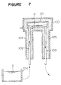
- this apparatus is employed in a process wherein molten glass G as a molten substance at elevated temperature in a melting tank 106, is degassed and is continuously fed to a successive treatment furnace.
- a vacuum housing 100 which is sucked in vacuum, accommodates a vacuum degassing vessel 101.
- This vacuum degassing vessel 101 is connected to an uprising pipe 102 wherein the molten glass G rises as a molten substance at elevated temperature before degassing, and is introduced into the vacuum degassing vessel 101.
- the vacuum degassing vessel 101 is connected to a downfalling pipe 103 wherein the molten glass G after degassing falls and is led out to a successive treatment furnace.
- Casings 104 and 105 are provided around the uprising pipe 102 and the downfalling pipe 103, respectively, for insulatively coating the uprising pipe 102 and the downfalling pipe 103, which are connected to the vacuum housing 100.
- the uprising pipe 102 and the downfalling pipe 103 are made of noble metals such as platinum, since temperatures of these pipes are elevated up to 1200 to 1500°C by the molten glass G.
- a pressure inside the vacuum degassing vessel 101 is reduced to 1/20 to 1/3 atmospheric pressure. Therefore, it is necessary to set a difference of levels of the molten glass G in the melting tank 106 and the molten glass G in the vacuum degassing vessel 101, to be approximately 3.5 m. Accordingly, since lengths of the uprising pipe 102 and the downfalling pipe 103 are prolonged, the thermal expansion quantities of the uprising pipe 102 and the downfalling pipe 103, are enlarged. Accordingly, the structure of the vacuum degassing apparatus becomes unstable and is devoid of safety.
- the molten glass G is led from the uprising pipe 102 to the downfalling pipe 103 only by decompression in the vacuum degassing vessel 101, the flow control of the molten glass G is difficult.
- a vacuum degassing method wherein a molten substance at an elevated temperature in a storage tank is sucked to a vacuum degassing vessel through an uprising pipe connecting the storage tank and the vacuum degassing vessel by maintaining the vacuum degassing vessel at a negative pressure, the molten substance is degassed and the degassed molten substance falls to a guiding duct through a downfalling pipe connecting the vacuum degassing vessel and the guiding duct characterized by that a first flow quantity of the molten substance rising in the uprising pipe is restrained and a second flow quantity thereof falling in the downfalling pipe is controlled thereby maintaining a quantity of the molten substance in the vacuum degassing vessel at a pertinent amount.
- a vacuum degassing method wherein the quantity of the molten substance is maintained at a pertinent amount by restraining the first flow quantity of the molten substance rising in the uprising pipe and by controlling the second flow quantity thereof falling in the downfalling pipe, and a first surface of material of the molten substance in the vacuum degassing vessel is maintained at a first level being the same with a second level of a second surface thereof in the storage tank.
- a vacuum degassing apparatus comprising: a vacuum housing being sucked in vacuum; a vacuum degassing vessel accommodated in the vacuum housing for degassing a molten substance at an elevated temperature; an uprising pipe connected to the vacuum degassing vessel for rising and introducing the molten substance before degassing into the vacuum degassing vessel; a downfalling pipe connected to the vacuum degassing vessel for falling and leading out the molten substance degassed by the vacuum degassing vessel; a first flow quantity controlling means provided in the uprising pipe for restraining a first flow quantity of the molten substance rising in the uprising pipe; and a second flow quantity controlling means provided in the downfalling pipe for controlling a second flow quantity of the molten substance falling in the downfalling pipe.
- a vacuum degassing apparatus according to the third aspect, wherein the first and the second flow quantity controlling means maintain a first surface of the molten substance in the vacuum degassing device at a first level the same with a second level of a second surface thereof in storage before degassing.
- the flow quantity of the molten substance at elevated temperature rising in the uprising pipe is restrained by the first flow quantity controlling means, and the flow quantity of the molten substance at elevated temperature falling in the downfalling pipe, is increased by the second flow quantity controlling means, thereby maintaining the molten substance at elevated temperature in the vacuum degassing vessel at a pertinent amount.
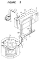
- Figures 1 and 2 show a first embodiment of an example of a process wherein molten glass is degassed and is continuously fed to a successive treatment furnace.
- a melting tank 1 heats molten glass G by plate-like electrodes 1a, and a guiding duct 2 is connected to the bottom of a side wall of the melting tank 1.
- the guiding duct 2 leads the molten glass G from the melting tank 1 to a storage tank 3, while heating the molten glass G by rod-like electrodes 2a.
- the storage tank 3 temporarily stores the molten glass G.
- the molten glass G stored in the storage tank 3 is degassed in a vacuum degassing vessel of the vacuum degassing apparatus 4 under a reduced pressure.
- the reduced pressure in the vacuum degassing vessel in this case is set to be 1/20 to 1/3 atmospheric pressure.
- a difference H between levels of the molten glass G in the melting tank and the molten glass G in the vacuum degassing vessel is set to be smaller than a level difference to which the "siphon" principle is applicable.
- the pressure in the vacuum degassing vessel is set to be 1/20 to 1/3 atmospheric pressure
- the difference between the levels of the molten glass G in the melting tank and the molten glass G in the vacuum degassing vessel is to be approximately 3.5 m to apply the "siphon" principle to the vacuum degassing apparatus 4, which is well known.
- the difference H between the levels of the molten glass G in the melting tank and the molten glass G in the vacuum degassing vessel is set to be smaller than 3.5 m.
- the degassed molten glass G is led to a guiding duct 5 which communicates with the storage tank 3.
- a partition plate 6 is provided between the storage tank 3 and the guiding duct 5. The partition plate 6 maintains the storage tank 3 and the guiding duct 5 in a closed state.
- the vacuum degassing apparatus 4 is provided with a vacuum housing 11 made of stainless steel.
- the vacuum housing 11 is sucked in vacuum by a vacuum pump 10.
- a vacuum degassing vessel 12 is provided in the vacuum housing 11.
- An uprising pipe 13 made of platinum is fixedly connected to a side of the bottom of the vacuum degassing vessel 12, and the lower end portion of the uprising pipe 13 is immersed in the molten glass G stored in the storage tank 3.
- a downcoming pipe 14 is connected to the other side of the bottom of the vacuum degassing vessel 12, which is made of platinum as in the uprising pipe 13.
- the lower end portion of the downfalling pipe 14 is immersed in the molten glass G in the guiding duct 5.
- the position of the lower end portion of the downfalling pipe 14 is set to be a little lower than that of the uprising pipe 13.
- the uprising pipe 13 and the downfalling pipe 14 are heated by electricity based on a temperature control system, not shown, and are maintained at predetermined temperatures.
- casings 15 and 16 made of stainless steel are provided around the uprising pipe 13 and the downfalling pipe 14, respectively.
- the casings 15 and 16 are connected to the vacuum housing 11.
- the lower end portions of the uprising pipe 13 and the downfalling pipe 14 are exposed to outside from openings 15A and 16A of the casings 15 and 16.
- An insulating material 17 is provided in the vacuum housing 11, and the casings 15 and 16, surrounding the uprising pipe 13 and the downfalling pipe 14.
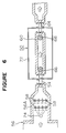
- a screw 20 and a screw 21 are rotatably and coaxially provided in the uprising pipe 13 and the downfalling pipe 14.
- the screws 20 and 21 are made of platinum.
- the screw 20 is consisted of a shaft 20A and a blade 20B.
- the blade 20B is helically provided on the shaft 20A, so that the blade 20B pushes down the molten glass G in the downward direction, when the shaft 20A rotates in the clockwise direction.
- the screw 21 is consisted of a shaft 21A and a blade 21B as in the screw 20, which pushes down the molten glass G in the downward direction, when the shaft 21/A rotates in the clockwise direction.
- Top end portions of the shafts 20A and 21A are connected with motors (not shown), which rotate the screws 20 and 21 in the clockwise direction.
- the molten glass G is introduced into the vacuum degassing apparatus 4.
- the partition plate 6 is opened, the molten glass G in the storage tank 3 is introduced into the side of the guiding duct 5, and the lower end portions of the uprising pipe 13 and the downfalling pipe 14 are immersed in the molten glass G.
- the vacuum pump 10 is operated and the inside of the vacuum degassing vessel 12 is made into a negative pressure state of 1/20 to 1/3 atmospheric pressure.
- the molten glass G is sucked to rise through the uprising pipe 13 and the downfalling pipe 14, into the vacuum degassing vessel 12. Accordingly, the molten glass G is introduced into the vacuum degassing device 4. However, since the difference between the levels of the molten glass G in the melting tank and the molten glass G in the vacuum degassing vessel is set to be smaller than the level difference for sufficiently operating the "siphon" principle, the molten glass G overflows in the vacuum degassing vessel.
- the apparatus is operated as follows.
- the screws 20 and 21 are rotated in the clockwise direction by driving motors (not shown) connected to the screws 20 and 21, the molten glass G rising in the uprising pipe 13 and the downfalling pipe 14, is pushed down in the downward direction, by the blades 20B and 21B. Accordingly, the rising flow rate of the molten glass G rising in the uprising pipe 13 and the downfalling pipe 14, is retarded.
- the rising flow rate of the molten glass G rising in the uprising pipe 13 and the downfalling pipe 14 is controlled so that the molten glass G moves from the uprising pipe 13 to the downfalling pipe 14, as in the "siphon" principle.
- the molten glass G which has risen through the uprising pipe 13 and has been degassed in the vacuum degassing vessel 12 is introduced to the side of the guiding duct 5 through the downfalling pipe 14.
- the flow rate of the molten glass G rising in the uprising pipe 13 is the same with the flow rate of the molten glass G falling in the downfalling pipe 14.
- the difference H between the levels of the molten glass G in the melting tank and the molten glass G in the vacuum degassing vessel, which is necessitated in the conventional vacuum degassing apparatus which is not provided with the screws 20 and 21, can be set at a small value.
- the uprising quantity of the molten glass G rising in the uprising pipe 13 is reduced by the screw 20 and the downfalling quantity of the molten glass G falling in the downfalling pipe 14, is increased by the screw 21. Therefore, the rising quantity of the molten glass G rising in the uprising pipe 13 and the downfalling quantity of the molten glass G falling in the downfalling pipe 14, can be controlled to the same one.
- the difference H between the levels of the molten glass G in the melting tank and the molten glass G in the vacuum degassing vessel can be set to be smaller than approximately 3.5 m which is necessary for the conventional apparatus, when the pressure in the vacuum degassing vessel is set to be 1/20 to 1/3 atmospheric pressure.
- the flow rate of the molten glass G can easily be controlled.
- the difference H between the levels of the molten glass G in the melting tank and the molten glass G in the vacuum degassing vessel is set to be smaller than the level difference to which the "siphon" principle is applicable.
- a vacuum degassing apparatus 50 of the second embodiment is provided with an uprising pipe 52.
- the lower end portion of the uprising pipe 52 is connected to a cooling tank 56 through a connecting pipe 54.
- the upper portion of the uprising pipe 52 is connected to the left end portion of the bottom of a vacuum degassing vessel 60.
- the upper portion of a downfalling pipe 62 is connected to the right end portion of the bottom of the vacuum degassing vessel 60.
- the bottom of the downfalling pipe 52 is connected to a spout of a successive step through a connecting pipe 64 or the like.
- the reduced pressure in the vacuum degassing vessel 60 is set to be 1/20 to 1/3 atmospheric pressure as in the first embodiment.
- a screw 66 and a screw 68 are rotatably and coaxially provided in the uprising pipes 52 and in the downfalling pipe 62, respectively.
- the screws 66 and 68 are composed similar to the screws 20 and 21 in the first embodiment.
- a blade 66B and a blade 68B are helically provided on a shaft 66A of the screw 66 and a shaft 68A of the screw 68, respectively. When the shaft 66A and the shaft 68A rotate in a constant direction, the blade 66B and the blade 68B push down the molten glass G in the uprising pipe 52 and the downfalling pipe 62 in the downward direction.
- the rotational speeds of the shaft 66A and the shaft 68A are controlled so that surfaces of the molten glass G in the vacuum degassing vessel 60 and the molten glass G in the cooling tank 66 are on the same level. Accordingly, since it is not necessary to elevate the molten glass G at an elevated temperature to a high position (by the difference H between the levels of the molten glass G in the melting tank and the molten glass G in the vacuum degassing vessel as in the first embodiment), the safety thereof is promoted. Furthermore, since it is not necessary to provide the vacuum degassing vessel 60 or the like at a high position, magnifying of facilities and cost reduction of facilities are enabled.
- a vacuum housing 72 in the vacuum degassing apparatus 50 is sucked in vacuum by a vacuum pump (not shown) as in the first embodiment.
- the screws are employed as the first and the second flow quantity controlling means.
- this invention is not restricted by these examples and may employ other flow quantity controlling means.
- a plunger of which lower end portion is formed in a conical form or the like may be considered.
- the conical portions of the plunger is fitted to an upper end portion of each of the rising pipes 13 and 52, and an opening ratio of each of the uprising pipes 13 and 52 is controlled, thereby controlling the rising quantity of the molten glass G.
- a colorant feeder 74 is provided at the upstream portion of a mixing area 56A.
- the lower end portion of the colorant feeder 74 is situated above the molten glass G.
- a colorant 76 is charged into the molten glass G from the lower end portion of the colorant feeder 74.
- stirrers 58 are rotated and the molten glass G is stirred to maintain the homogeneous distribution of the charged colorant 76, bubbles are generated in the molten glass G.
- the molten glass G generated with bubbles is introduced to the lower end portion of the uprising pipe 52 through the connecting pipe 54.
- the molten glass introduced to the lower end portion of the uprising pipe 52 rises in the uprising pipe 52.
- the screw 66 since the screw 66 is rotating, the molten glass G is pushed down in the downward direction by the blade 66B of the screw 66. Accordingly, the rising quantity of the molten glass G is restrained.
- the pressure in the vacuum degassing vessel 60 is reduced to 1/2 to 1/3 atmospheric pressure, the molten glass G introduced into the vacuum degassing vessel 60 by rising in the uprising pipe 52, is degassed in the vacuum degassing vessel 60. Accordingly, the bubbles are removed from the molten glass G.
- the screw 68 since the screw 68 is rotating in the downfalling pipe 62 at this state, the molten glass G in the degassed state is pushed down in the downward direction by the blade 68B of the screw 68. Accordingly, the molten glass G falls in the downfalling pipe 62 and is discharged from the vacuum degassing vessel 60. In this way, the bubbles can be removed from the molten glass G charged with the colorant 76.
- the stirring operates to uniformly distribute the material in the melting tank and the colorant, and the reduced pressure operates to rapidly enlarge the bubbles generated in the stirring chamber and to remove them by floating them. Accordingly, in case of the change of the material to change the color tone of the glass, this invention has an excellent effect in saving the raw material cost and the energy cost and an effect in making homogeneous colored glass. Furthermore, this invention has an effect of reducing bubbles in glass.
- the molten glass G added with the colorant 76 is not restricted with respect to the composition so far as the glass is made by the heat-melting method.
- lime-silica series glass employed as ordinary window glass and borosilicate glass employed as vessel glass are pointed out.
- Such molten glass can be provided by continuously charging the raw material which is controlled to have a target composition, and by heating and melting the raw material.
- a metallic ion of Ti, V, Cr, Mn, Fe, Co, Ni, Cu, Mo, Ce or the like, a metallic selenium of an element-like selenium, is pointed out.
- the kind and the addition quantity of the colorant is determined by a target color tone of glass.
- such colorant may be added in an oxide form or in a metallic form, it is particularly preferable to add the colorant as colored frits previously mixed in frits having a low melting point, since the homogeneous distribution of the colorant in the molten glass, is facilitated.
- the stirrers 58 stirring the molten glass added with such colorant, are immersed in the molten glass.
- the stirrer 58 is of a publicly known type provided with a stirring blade attached to a rod-like rotating shaft.
- a stirrer performing a comb-like reciprocating motion can be employed instead of the stirrer 58.
- the stirrer or the stirrers can be provided singularly or plurally in the direction of flow of the molten glass (in case of Figures 5 and 6, two of them are provided in the direction of flow of the molten glass).
- the stirring may be preformed when the colorant is added.
- the viscosity of glass in performing the stirring is preferably to be 102 to 103 poise.
- the viscosity of glass is smaller than 102 poise, the wear of the stirrer becomes considerable, whereas, when the viscosity is larger than 103 poise, the molten glass and the colorant are difficult to mix together uniformly, which is not preferable.
- the molten glass uniformly mixed with the colorant is degassed under the reduced pressure.
- a value of 1/20 to 1/3 atmospheric pressure is preferable.
- the pressure is higher than 1/3 atmospheric pressure, the degassing action is deteriorated, which is not preferable.
- the apparatus is magnified, which is not preferable.
- the time of holding the glass under the reduced pressure, and the viscosity of glass depend on a quantity of allowable residual bubbles. For instance, in case of allowing bubbles of 0.1 particle per kg, the purpose of decreasing bubbles can sufficiently achieved by the viscosity of glass of 102 to 10 2.5 poise and the holding time of approximately 0.5 to 2 hours.
- the glass which is removed of the bubbles as above, is controlled of its temperature to a predetermined temperature, is transmitted to a floating bath or the like and is formed continuously.
- the color tone of the material can be changed by changing the colorant while the molten glass in the melting tank remains as it is.
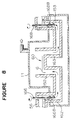
- a first downfalling pipe 162 is provided at the end of the cooling tank 56.
- the bottom thereof is connected to the bottom of a first uprising pipe 152.
- the upper end portion of the first uprising pipe 152 is connected to the vacuum degassing vessel 60.
- the downstream end of the vacuum degassing vessel 60 is connected to the upper end portion of a second downfalling pipe 163.
- the bottom of the second downfalling pipe 163 is connected to the bottom of a second uprising pipe 153.
- the first downfalling pipe 162 is provided with a screw 166 wherein a blade 166B is helically provided.
- the screw 166B rotates in the directions of the arrow mark, operates to pull up the falling molten glass in the upward direction, and, as a result, controls the flow quantity of the molten glass G rising in the first uprising pipe 152.
- the second uprising pipe 153 is provided with a screw 168 having a helical blade 168B. This screw rotates in the direction of the arrow mark, and operates to pull up the rising molten glass. As a result, the flow quantity of the molten glass falling in the second downfalling pipe 163, is controlled.
- the glass surface in the vacuum degassing vessel 60 and the glass surface in the cooling tank 56 are controlled to be approximately on the same level, by these screws 166 and 168.
- the lower end portion of the first downfalling pipe 162, the lower end portion of the second uprising pipe 153, the first uprising pipe 152, the vacuum degassing vessel 60 and the second downfalling pipe 163 are all arranged in the vacuum housing 11.
- the upper end portion of the first downfalling pipe 162, the upper end portion of the second uprising pipe 153 and the upper end portions of the screws 166 and 168 are all arranged outside the vacuum housing 11.
- the pressure inside the vacuum housing 11 is set to be 1/20 to 1/3 atmospheric pressure as in the first and the second embodiments.
- seals are not necessary. Therefore, this is a particularly preferable device.
- the vacuum degassing vessels and its apparatus of this invention even when the the height of the vacuum degassing vessel is set to be low, the rising quantity of the molten substance at elevated temperature in the uprising pipe and the falling quantity of the molten substance in the downfalling pipe, can be controlled to the same quantity. Accordingly, it becomes possible to reduce the level difference between the molten substance in the vacuum degassing vessel and that in the storage tank and the guiding ducts, or to nullify the level difference. Accordingly, since the lengths of the uprising pipe and the downfalling pipe can be set to be short, the promotion of the safety of the vacuum degassing apparatus can be achieved.
Landscapes
- Chemical & Material Sciences (AREA)
- Engineering & Computer Science (AREA)
- Materials Engineering (AREA)
- Organic Chemistry (AREA)
- Metallurgy (AREA)
- Manufacturing & Machinery (AREA)
- Mechanical Engineering (AREA)
- Treatment Of Steel In Its Molten State (AREA)
- Degasification And Air Bubble Elimination (AREA)
Abstract
In another embodiment (see figure 8), the bottom of the uprising pipe (152) of the vacuum degassing vessel (11) is connected upstream via a horizontal passage to a second downfalling pipe (162) and the bottom of the downfalling pipe (163) of the vacuum vessel is connected via a further horizontal passage to a second uprising pipe (153). In this embodiment the means for restraining (166B) and controlling (168B) the flow are mounted in the upstream second downfalling pipe (162) and downstream second uprising pipe (153) respectively and both means are positioned outside the vacuum housing (11).
Description
- This invention relates to a vacuum degassing method and its apparatus for removing bubbles in a molten substance at elevated temperature such as molten glass or molten metal, particularly to a vacuum degassing method and an improvement of its apparatus which is effective in a process for continuously feeding molten substance at elevated temperature.
- Conventionally, as such a vacuum degassing apparatus, there is one disclosed, for instance, in Japanese Examined patent Publication No. 4205/1969.
- As shown in Figure 7, this apparatus is employed in a process wherein molten glass G as a molten substance at elevated temperature in a
melting tank 106, is degassed and is continuously fed to a successive treatment furnace. As shown in Figure 7, avacuum housing 100 which is sucked in vacuum, accommodates avacuum degassing vessel 101. Thisvacuum degassing vessel 101 is connected to anuprising pipe 102 wherein the molten glass G rises as a molten substance at elevated temperature before degassing, and is introduced into thevacuum degassing vessel 101. Thevacuum degassing vessel 101 is connected to adownfalling pipe 103 wherein the molten glass G after degassing falls and is led out to a successive treatment furnace.Casings uprising pipe 102 and thedownfalling pipe 103, respectively, for insulatively coating theuprising pipe 102 and thedownfalling pipe 103, which are connected to thevacuum housing 100. - Furthermore, the
uprising pipe 102 and thedownfalling pipe 103 are made of noble metals such as platinum, since temperatures of these pipes are elevated up to 1200 to 1500°C by the molten glass G. - In the vacuum degassing apparatus of this kind, a pressure inside the vacuum degassing
vessel 101, is reduced to 1/20 to 1/3 atmospheric pressure. Therefore, it is necessary to set a difference of levels of the molten glass G in themelting tank 106 and the molten glass G in thevacuum degassing vessel 101, to be approximately 3.5 m. Accordingly, since lengths of theuprising pipe 102 and thedownfalling pipe 103 are prolonged, the thermal expansion quantities of theuprising pipe 102 and thedownfalling pipe 103, are enlarged. Accordingly, the structure of the vacuum degassing apparatus becomes unstable and is devoid of safety. - Furthermore, since, in the vacuum degassing apparatus of this kind, the molten glass G is led from the
uprising pipe 102 to the downfallingpipe 103 only by decompression in thevacuum degassing vessel 101, the flow control of the molten glass G is difficult. - It is an object of the present invention to provide a vacuum degassing method and its apparatus wherein the safety of the vacuum degassing apparatus is promoted and the flow quantity control of the molten glass is facilitated.
- According to a first aspect of this invention, there is provided a vacuum degassing method wherein a molten substance at an elevated temperature in a storage tank is sucked to a vacuum degassing vessel through an uprising pipe connecting the storage tank and the vacuum degassing vessel by maintaining the vacuum degassing vessel at a negative pressure, the molten substance is degassed and the degassed molten substance falls to a guiding duct through a downfalling pipe connecting the vacuum degassing vessel and the guiding duct characterized by that a first flow quantity of the molten substance rising in the uprising pipe is restrained and a second flow quantity thereof falling in the downfalling pipe is controlled thereby maintaining a quantity of the molten substance in the vacuum degassing vessel at a pertinent amount.
- According to a second aspect of this invention, there is provided a vacuum degassing method according to the first aspect, wherein the quantity of the molten substance is maintained at a pertinent amount by restraining the first flow quantity of the molten substance rising in the uprising pipe and by controlling the second flow quantity thereof falling in the downfalling pipe, and a first surface of material of the molten substance in the vacuum degassing vessel is maintained at a first level being the same with a second level of a second surface thereof in the storage tank.
- According to a third aspect of this invention, there is provided a vacuum degassing apparatus comprising:
a vacuum housing being sucked in vacuum;
a vacuum degassing vessel accommodated in the vacuum housing for degassing a molten substance at an elevated temperature;
an uprising pipe connected to the vacuum degassing vessel for rising and introducing the molten substance before degassing into the vacuum degassing vessel;
a downfalling pipe connected to the vacuum degassing vessel for falling and leading out the molten substance degassed by the vacuum degassing vessel;
a first flow quantity controlling means provided in the uprising pipe for restraining a first flow quantity of the molten substance rising in the uprising pipe; and
a second flow quantity controlling means provided in the downfalling pipe for controlling a second flow quantity of the molten substance falling in the downfalling pipe. - According to a fourth aspect of this invention, there is provided a vacuum degassing apparatus according to the third aspect, wherein the first and the second flow quantity controlling means maintain a first surface of the molten substance in the vacuum degassing device at a first level the same with a second level of a second surface thereof in storage before degassing.
- According to the present invention, the flow quantity of the molten substance at elevated temperature rising in the uprising pipe, is restrained by the first flow quantity controlling means, and the flow quantity of the molten substance at elevated temperature falling in the downfalling pipe, is increased by the second flow quantity controlling means, thereby maintaining the molten substance at elevated temperature in the vacuum degassing vessel at a pertinent amount.
- Accordingly, it is possible to reduce the difference between the levels of the molten substance in the vacuum degassing vessel and that in a storage tank and the guiding duct, or to nullify the level difference. In this way, since the lengths of the uprising pipe and the downfalling pipe can be set to be short, the thermal expansion quantities of the uprising pipe and the downfalling pipe can be reduced.
- Figure 1 is a sectional diagram showing the side of a process integrated with a first embodiment of a vacuum degassing apparatus according to the present invention;
- Figure 2 is a perspective view of Figure 1;
- Figure 3 is a sectional diagram showing the first embodiment of a vacuum degassing apparatus according to the present invention;
- Figure 4 is a sectional diagram showing the side of a process integrated with a second embodiment of a vacuum degassing apparatus according to the present invention;
- Figure 5 is a sectional diagram showing an apparatus employed in a third embodiment of a method of making colored glass;
- Figure 6 is a sectional diagram taken along a line A-A of Figure 5;
- Figure 7 is a sectional diagram of a conventional vacuum degassing apparatus; and
- Figure 8 is a sectional diagram of a fourth embodiment of a vacuum degassing apparatus according to the present invention.
- A detailed explanation will be given of a vacuum degassing method and its apparatus according to the present invention in reference to the attached drawings, as follows.
- Figures 1 and 2 show a first embodiment of an example of a process wherein molten glass is degassed and is continuously fed to a successive treatment furnace.
- As shown in Figures 1 and 2, a melting tank 1 heats molten glass G by plate-
like electrodes 1a, and a guidingduct 2 is connected to the bottom of a side wall of the melting tank 1. The guidingduct 2 leads the molten glass G from the melting tank 1 to astorage tank 3, while heating the molten glass G by rod-like electrodes 2a. Thestorage tank 3 temporarily stores the molten glass G. The molten glass G stored in thestorage tank 3 is degassed in a vacuum degassing vessel of the vacuum degassing apparatus 4 under a reduced pressure. The reduced pressure in the vacuum degassing vessel in this case is set to be 1/20 to 1/3 atmospheric pressure. - Furthermore, a difference H between levels of the molten glass G in the melting tank and the molten glass G in the vacuum degassing vessel, is set to be smaller than a level difference to which the "siphon" principle is applicable. Generally speaking, when the pressure in the vacuum degassing vessel is set to be 1/20 to 1/3 atmospheric pressure, the difference between the levels of the molten glass G in the melting tank and the molten glass G in the vacuum degassing vessel, is to be approximately 3.5 m to apply the "siphon" principle to the vacuum degassing apparatus 4, which is well known. Accordingly, in the vacuum degassing apparatus 4, the difference H between the levels of the molten glass G in the melting tank and the molten glass G in the vacuum degassing vessel, is set to be smaller than 3.5 m.
- Furthermore, the degassed molten glass G is led to a guiding
duct 5 which communicates with thestorage tank 3. A partition plate 6 is provided between thestorage tank 3 and the guidingduct 5. The partition plate 6 maintains thestorage tank 3 and the guidingduct 5 in a closed state. - As shown in Figure 2, the vacuum degassing apparatus 4 is provided with a
vacuum housing 11 made of stainless steel. Thevacuum housing 11 is sucked in vacuum by avacuum pump 10. Avacuum degassing vessel 12 is provided in thevacuum housing 11. Anuprising pipe 13 made of platinum is fixedly connected to a side of the bottom of thevacuum degassing vessel 12, and the lower end portion of theuprising pipe 13 is immersed in the molten glass G stored in thestorage tank 3. - On the other hand, a
downcoming pipe 14 is connected to the other side of the bottom of thevacuum degassing vessel 12, which is made of platinum as in theuprising pipe 13. The lower end portion of thedownfalling pipe 14 is immersed in the molten glass G in the guidingduct 5. The position of the lower end portion of the downfallingpipe 14 is set to be a little lower than that of theuprising pipe 13. Theuprising pipe 13 and thedownfalling pipe 14 are heated by electricity based on a temperature control system, not shown, and are maintained at predetermined temperatures. - Furthermore,
casings uprising pipe 13 and thedownfalling pipe 14, respectively. Thecasings vacuum housing 11. The lower end portions of theuprising pipe 13 and the downfallingpipe 14 are exposed to outside fromopenings 15A and 16A of thecasings insulating material 17 is provided in thevacuum housing 11, and thecasings uprising pipe 13 and the downfallingpipe 14. - As shown in Figure 3, a
screw 20 and ascrew 21 are rotatably and coaxially provided in theuprising pipe 13 and thedownfalling pipe 14. Thescrews screw 20 is consisted of ashaft 20A and ablade 20B. Theblade 20B is helically provided on theshaft 20A, so that theblade 20B pushes down the molten glass G in the downward direction, when theshaft 20A rotates in the clockwise direction. - Furthermore, the
screw 21 is consisted of ashaft 21A and ablade 21B as in thescrew 20, which pushes down the molten glass G in the downward direction, when theshaft 21/A rotates in the clockwise direction. Top end portions of theshafts screws - An explanation will be given of the operation of the first embodiment of the vacuum degassing device according to the present invention, composed as above.
- First, as a pre-stage for operating the vacuum degassing apparatus 4, the molten glass G is introduced into the vacuum degassing apparatus 4. The partition plate 6 is opened, the molten glass G in the
storage tank 3 is introduced into the side of the guidingduct 5, and the lower end portions of theuprising pipe 13 and thedownfalling pipe 14 are immersed in the molten glass G. After the immersing is finished, thevacuum pump 10 is operated and the inside of thevacuum degassing vessel 12 is made into a negative pressure state of 1/20 to 1/3 atmospheric pressure. - The molten glass G is sucked to rise through the
uprising pipe 13 and thedownfalling pipe 14, into thevacuum degassing vessel 12. Accordingly, the molten glass G is introduced into the vacuum degassing device 4. However, since the difference between the levels of the molten glass G in the melting tank and the molten glass G in the vacuum degassing vessel is set to be smaller than the level difference for sufficiently operating the "siphon" principle, the molten glass G overflows in the vacuum degassing vessel. - To prevent the overflow, the apparatus is operated as follows. When the
screws screws uprising pipe 13 and thedownfalling pipe 14, is pushed down in the downward direction, by theblades uprising pipe 13 and thedownfalling pipe 14, is retarded. In this case, the rising flow rate of the molten glass G rising in theuprising pipe 13 and thedownfalling pipe 14, is controlled so that the molten glass G moves from theuprising pipe 13 to thedownfalling pipe 14, as in the "siphon" principle. - When the partition plate 6 is closed at this stage, the molten glass G which has risen through the
uprising pipe 13 and has been degassed in thevacuum degassing vessel 12, is introduced to the side of the guidingduct 5 through thedownfalling pipe 14. In this case, the flow rate of the molten glass G rising in theuprising pipe 13 is the same with the flow rate of the molten glass G falling in thedownfalling pipe 14. In this way, the difference H between the levels of the molten glass G in the melting tank and the molten glass G in the vacuum degassing vessel, which is necessitated in the conventional vacuum degassing apparatus which is not provided with thescrews - Accordingly, even when the difference H between the levels of the molten glass G in the melting tank and the molten glass G in the vacuum degassing vessel, is set to be small, by providing the
screws uprising pipe 13 is reduced by thescrew 20 and the downfalling quantity of the molten glass G falling in thedownfalling pipe 14, is increased by thescrew 21. Therefore, the rising quantity of the molten glass G rising in theuprising pipe 13 and the downfalling quantity of the molten glass G falling in thedownfalling pipe 14, can be controlled to the same one. Accordingly, the difference H between the levels of the molten glass G in the melting tank and the molten glass G in the vacuum degassing vessel, can be set to be smaller than approximately 3.5 m which is necessary for the conventional apparatus, when the pressure in the vacuum degassing vessel is set to be 1/20 to 1/3 atmospheric pressure. - In this way, the molten glass G which has passed through the vacuum degassing device 4, is led to the guiding
duct 5. - Furthermore, by changing the rotational speeds of the
screws - In the first example, the difference H between the levels of the molten glass G in the melting tank and the molten glass G in the vacuum degassing vessel, is set to be smaller than the level difference to which the "siphon" principle is applicable. However, as in a second embodiment shown in Figure 4, it is possible to set the respective surfaces of the molten glass G in the melting tank and the molten glass G in the vacuum degassing vessel, to the same level, by nullifying the level difference between the molten glass G in the melting tank and the molten glass in the vacuum degassing vessel.
- A detailed explanation will be given of a second embodiment of a vacuum degassing method and its apparatus according to the present invention in reference to Figure 4, as follows.
- As shown in Figure 4, a
vacuum degassing apparatus 50 of the second embodiment is provided with anuprising pipe 52. The lower end portion of theuprising pipe 52 is connected to acooling tank 56 through a connectingpipe 54. Furthermore, the upper portion of theuprising pipe 52 is connected to the left end portion of the bottom of avacuum degassing vessel 60. The upper portion of adownfalling pipe 62 is connected to the right end portion of the bottom of thevacuum degassing vessel 60. The bottom of thedownfalling pipe 52 is connected to a spout of a successive step through a connectingpipe 64 or the like. The reduced pressure in thevacuum degassing vessel 60 is set to be 1/20 to 1/3 atmospheric pressure as in the first embodiment. - A
screw 66 and ascrew 68 are rotatably and coaxially provided in theuprising pipes 52 and in thedownfalling pipe 62, respectively. Thescrews screws blade 66B and ablade 68B are helically provided on ashaft 66A of thescrew 66 and ashaft 68A of thescrew 68, respectively. When theshaft 66A and theshaft 68A rotate in a constant direction, theblade 66B and theblade 68B push down the molten glass G in theuprising pipe 52 and thedownfalling pipe 62 in the downward direction. - In this case, the rotational speeds of the
shaft 66A and theshaft 68A are controlled so that surfaces of the molten glass G in thevacuum degassing vessel 60 and the molten glass G in thecooling tank 66 are on the same level. Accordingly, since it is not necessary to elevate the molten glass G at an elevated temperature to a high position (by the difference H between the levels of the molten glass G in the melting tank and the molten glass G in the vacuum degassing vessel as in the first embodiment), the safety thereof is promoted. Furthermore, since it is not necessary to provide thevacuum degassing vessel 60 or the like at a high position, magnifying of facilities and cost reduction of facilities are enabled. - A
vacuum housing 72 in thevacuum degassing apparatus 50, is sucked in vacuum by a vacuum pump (not shown) as in the first embodiment. - In the above first and the second embodiments, the screws are employed as the first and the second flow quantity controlling means. However, this invention is not restricted by these examples and may employ other flow quantity controlling means. As the other flow quantity controlling means, for instance, a plunger of which lower end portion is formed in a conical form or the like, may be considered. The conical portions of the plunger is fitted to an upper end portion of each of the rising
pipes uprising pipes - Furthermore, in the above first and second embodiments, explanation has been given to cases wherein transparent glass is produced. However, the vacuum degassing method and its apparatus of this invention can be employed in the production of colored glass. An explanation will be given of a third embodiment of a method for making colored glass in reference to Figures 5 and 6, as follows. A member similar to or the same with the member in Figure 4 of the second embodiment, is attached with the same notation and the explanation will be omitted.
- A
colorant feeder 74 is provided at the upstream portion of amixing area 56A. The lower end portion of thecolorant feeder 74 is situated above the molten glassG. A colorant 76 is charged into the molten glass G from the lower end portion of thecolorant feeder 74. In this case, sincestirrers 58 are rotated and the molten glass G is stirred to maintain the homogeneous distribution of the chargedcolorant 76, bubbles are generated in the molten glass G. - Furthermore, the molten glass G generated with bubbles is introduced to the lower end portion of the
uprising pipe 52 through the connectingpipe 54. The molten glass introduced to the lower end portion of theuprising pipe 52, rises in theuprising pipe 52. At this occasion, since thescrew 66 is rotating, the molten glass G is pushed down in the downward direction by theblade 66B of thescrew 66. Accordingly, the rising quantity of the molten glass G is restrained. - On the other hand, since the pressure in the
vacuum degassing vessel 60 is reduced to 1/2 to 1/3 atmospheric pressure, the molten glass G introduced into thevacuum degassing vessel 60 by rising in theuprising pipe 52, is degassed in thevacuum degassing vessel 60. Accordingly, the bubbles are removed from the molten glass G. - Furthermore, since the
screw 68 is rotating in thedownfalling pipe 62 at this state, the molten glass G in the degassed state is pushed down in the downward direction by theblade 68B of thescrew 68. Accordingly, the molten glass G falls in thedownfalling pipe 62 and is discharged from thevacuum degassing vessel 60. In this way, the bubbles can be removed from the molten glass G charged with thecolorant 76. - According to the method of making colored glass wherein the addition of the colorant, the stirring and the vacuum degassing are continuously performed, the stirring operates to uniformly distribute the material in the melting tank and the colorant, and the reduced pressure operates to rapidly enlarge the bubbles generated in the stirring chamber and to remove them by floating them. Accordingly, in case of the change of the material to change the color tone of the glass, this invention has an excellent effect in saving the raw material cost and the energy cost and an effect in making homogeneous colored glass. Furthermore, this invention has an effect of reducing bubbles in glass. In the above-mentioned method of making color glass, it is possible to make homogeneous colored glass having little bubbles, in a continuous tank furnace, considerably saving the raw material cost, the energy cost and the like, which are accompanied by the color changing in the continuous tank furnace. Therefore, the industrial value is great.
- In the method of making colored glass, the molten glass G added with the
colorant 76 is not restricted with respect to the composition so far as the glass is made by the heat-melting method. For instance, lime-silica series glass employed as ordinary window glass and borosilicate glass employed as vessel glass are pointed out. - As the viscosity of the molten glass in case of adding the
colorant 76, a value of 10³ poise or less is preferable. When the viscosity exceeds 10³ poise, thecolorant 76 is difficult to be mixed uniformly, which is not preferable. Such molten glass can be provided by continuously charging the raw material which is controlled to have a target composition, and by heating and melting the raw material. - As the colorant added to such molten glass, a metallic ion of Ti, V, Cr, Mn, Fe, Co, Ni, Cu, Mo, Ce or the like, a metallic selenium of an element-like selenium, is pointed out. The kind and the addition quantity of the colorant is determined by a target color tone of glass. Although such colorant may be added in an oxide form or in a metallic form, it is particularly preferable to add the colorant as colored frits previously mixed in frits having a low melting point, since the homogeneous distribution of the colorant in the molten glass, is facilitated.
- As shown in Figure 5, the
stirrers 58 stirring the molten glass added with such colorant, are immersed in the molten glass. Thestirrer 58 is of a publicly known type provided with a stirring blade attached to a rod-like rotating shaft. Furthermore, instead of thestirrer 58, a stirrer performing a comb-like reciprocating motion, can be employed. The stirrer or the stirrers can be provided singularly or plurally in the direction of flow of the molten glass (in case of Figures 5 and 6, two of them are provided in the direction of flow of the molten glass). Or, the stirring may be preformed when the colorant is added. - The viscosity of glass in performing the stirring, is preferably to be 10² to 10³ poise. When the viscosity of glass is smaller than 10² poise, the wear of the stirrer becomes considerable, whereas, when the viscosity is larger than 10³ poise, the molten glass and the colorant are difficult to mix together uniformly, which is not preferable. The molten glass uniformly mixed with the colorant is degassed under the reduced pressure. Furthermore, as the pressure in case of performing the degassing, a value of 1/20 to 1/3 atmospheric pressure is preferable. When the pressure is higher than 1/3 atmospheric pressure, the degassing action is deteriorated, which is not preferable. Conversely, when the pressure is lower than 1/20 atmospheric pressure, the apparatus is magnified, which is not preferable. Furthermore, the time of holding the glass under the reduced pressure, and the viscosity of glass depend on a quantity of allowable residual bubbles. For instance, in case of allowing bubbles of 0.1 particle per kg, the purpose of decreasing bubbles can sufficiently achieved by the viscosity of glass of 10² to 102.5 poise and the holding time of approximately 0.5 to 2 hours.
- The glass which is removed of the bubbles as above, is controlled of its temperature to a predetermined temperature, is transmitted to a floating bath or the like and is formed continuously.
- On the other hand, in case of changing the material for changing the color tone of the obtained glass, the color tone of the material can be changed by changing the colorant while the molten glass in the melting tank remains as it is.
- Next, an explanation will be given to a fourth embodiment of this invention in reference to Figure 8. This embodiment is a particularly preferable embodiment in this invention.
- At the end of the
cooling tank 56, afirst downfalling pipe 162 is provided. The bottom thereof is connected to the bottom of afirst uprising pipe 152. The upper end portion of thefirst uprising pipe 152 is connected to thevacuum degassing vessel 60. The downstream end of thevacuum degassing vessel 60 is connected to the upper end portion of asecond downfalling pipe 163. The bottom of thesecond downfalling pipe 163 is connected to the bottom of asecond uprising pipe 153. Thefirst downfalling pipe 162 is provided with ascrew 166 wherein a blade 166B is helically provided. The screw 166B rotates in the directions of the arrow mark, operates to pull up the falling molten glass in the upward direction, and, as a result, controls the flow quantity of the molten glass G rising in thefirst uprising pipe 152. Similarly, thesecond uprising pipe 153 is provided with ascrew 168 having ahelical blade 168B. This screw rotates in the direction of the arrow mark, and operates to pull up the rising molten glass. As a result, the flow quantity of the molten glass falling in thesecond downfalling pipe 163, is controlled. - The glass surface in the
vacuum degassing vessel 60 and the glass surface in thecooling tank 56 are controlled to be approximately on the same level, by thesescrews - The lower end portion of the
first downfalling pipe 162, the lower end portion of thesecond uprising pipe 153, thefirst uprising pipe 152, thevacuum degassing vessel 60 and thesecond downfalling pipe 163 are all arranged in thevacuum housing 11. On the other hand, the upper end portion of thefirst downfalling pipe 162, the upper end portion of thesecond uprising pipe 153 and the upper end portions of thescrews vacuum housing 11. - The pressure inside the
vacuum housing 11 is set to be 1/20 to 1/3 atmospheric pressure as in the first and the second embodiments. In the fourth embodiment, since movable portions of thescrews vacuum housing 11, seals are not necessary. Therefore, this is a particularly preferable device. - As stated above, according to the vacuum degassing vessels and its apparatus of this invention, even when the the height of the vacuum degassing vessel is set to be low, the rising quantity of the molten substance at elevated temperature in the uprising pipe and the falling quantity of the molten substance in the downfalling pipe, can be controlled to the same quantity. Accordingly, it becomes possible to reduce the level difference between the molten substance in the vacuum degassing vessel and that in the storage tank and the guiding ducts, or to nullify the level difference. Accordingly, since the lengths of the uprising pipe and the downfalling pipe can be set to be short, the promotion of the safety of the vacuum degassing apparatus can be achieved.
- Furthermore, since it is not necessary to bring the molten substance to a high position by nullifying the level difference between the surfaces of the molten substance in the vacuum degassing vessel and that in the storage tank and the guiding ducts, the safety is promoted.
- Furthermore, it is possible to easily control the flow quantities of the molten substance flowing in the uprising pipe and that in the downfalling pipe by the first and the second flow quantity controlling means.
Claims (7)
- A vacuum degassing method wherein a molten substance at an elevated temperature in a storage tank is sucked to a vacuum degassing vessel through an uprising pipe connecting the storage tank and the vacuum degassing vessel by maintaining the vacuum degassing vessel at a negative pressure, the molten substance is degassed and the degassed molten substance falls to a guiding duct through a downfalling pipe connecting the vacuum degassing vessel and the guiding duct characterized by that a first flow quantity of the molten substance rising in the uprising pipe is restrained and a second flow quantity thereof falling in the downfalling pipe is controlled thereby maintaining a quantity of the molten substance in the vacuum degassing vessel at a pertinent amount.
- The vacuum degassing method according to Claim 1, wherein the quantity of the molten substance is maintained at a pertinent amount by restraining the first flow quantity of the molten substance rising in the uprising pipe and by controlling the second flow quantity thereof falling in the downfalling pipe, and a first surface of material of the molten substance in the vacuum degassing vessel is maintained at a first level being the same with a second level of a second surface thereof in the storage tank.
- A vacuum degassing apparatus comprising:
a vacuum housing being sucked in vacuum;
a vacuum degassing vessel accommodated in the vacuum housing for degassing a molten substance at an elevated temperature;
an uprising pipe connected to the vacuum degassing vessel for rising and introducing the molten substance before degassing into the vacuum degassing vessel;
a downfalling pipe connected to the vacuum degassing vessel for falling and leading out the molten substance degassed by the vacuum degassing vessel;
a first flow quantity controlling means provided in the uprising pipe for restraining a first flow quantity of the molten substance rising in the uprising pipe; and
a second flow quantity controlling means provided in the downfalling pipe for controlling a second flow quantity of the molten substance falling in the downfalling pipe. - The vacuum degassing apparatus according to Claim 3, wherein the first and the second flow quantity controlling means maintain a first surface of the molten substance in the vacuum degassing device at a first level the same with a second level of a second surface thereof in storage before degassing.
- The vacuum degassing apparatus according to Claim 3 or Claim 4, wherein the first and the second flow quantity controlling means are screws rotatably and coaxially provided in the uprising pipe and the downfalling pipe, respectively.
- A vacuum degassing apparatus comprising:
a vacuum housing being sucked in vacuum;
a vacuum degassing vessel accommodated in the vacuum housing for degassing a molten substance at an elevated temperature;
a first uprising pipe connected to the vacuum degassing vessel for rising and introducing the molten substance before degassing into the vacuum degassing vessel;
a second downfalling pipe connected to the vacuum degassing vessel for falling and leading out the molten substance degassed by the vacuum degassing vessel;
a first downfalling pipe provided upstream of the first uprising pipe, the bottom of which is connected to the bottom of the first uprising pipe;
a second uprising pipe provided downstream of the second downfalling pipe, the bottom of which is connected to the bottom of the second downfalling pipe;
a first flow quantity controlling means provided in the first downfalling pipe for controlling a first flow quantity of the molten substance rising in the first uprising pipe; and
a second flow quantity controlling means provided in the second uprising pipe for controlling a second flow quantity of the molten substance falling in the second downfalling pipe;
wherein the tops of the first and the second flow quantity controlling means are provided outside the vacuum housing and the first and the second flow quantity controlling means maintain a first surface of the molten substance in the vacuum degassing device to a first level substantially the same with a second level of a second surface thereof in storage before degassing. - The vacuum degassing device according to Claim 6, wherein the first and the second flow controlling means are screws rotatably and coaxially provided in the first downfalling pipe and in the second uprising pipe, respectively.
Applications Claiming Priority (2)
| Application Number | Priority Date | Filing Date | Title |
|---|---|---|---|
| JP7694/92 | 1992-01-20 | ||
| JP769492 | 1992-01-20 |
Publications (2)
| Publication Number | Publication Date |
|---|---|
| EP0556576A1 true EP0556576A1 (en) | 1993-08-25 |
| EP0556576B1 EP0556576B1 (en) | 1997-04-23 |
Family
ID=11672882
Family Applications (1)
| Application Number | Title | Priority Date | Filing Date |
|---|---|---|---|
| EP93100809A Expired - Lifetime EP0556576B1 (en) | 1992-01-20 | 1993-01-20 | Method and apparatus for continuous vacuum degassing of molten materials |
Country Status (4)
| Country | Link |
|---|---|
| US (2) | US5316563A (en) |
| EP (1) | EP0556576B1 (en) |
| JP (1) | JP2664039B2 (en) |
| DE (1) | DE69309987T2 (en) |
Cited By (17)
| Publication number | Priority date | Publication date | Assignee | Title |
|---|---|---|---|---|
| EP0759524A1 (en) * | 1995-08-21 | 1997-02-26 | Asahi Glass Company Ltd. | Pipe with external insulation for feeding a molten substance at high temperature |
| EP0775671A1 (en) * | 1995-11-21 | 1997-05-28 | Asahi Glass Company Ltd. | Method and apparatus for refining molten glass under reduced pressure |
| WO1998005599A1 (en) * | 1996-08-03 | 1998-02-12 | Pilkington Plc | Process and apparatus for modifying and homogenizing glass melts |
| WO1998018731A2 (en) * | 1996-10-28 | 1998-05-07 | Corning Incorporated | Method of forming glasses |
| EP0908417A2 (en) * | 1997-10-06 | 1999-04-14 | Asahi Glass Company Ltd. | Vacuum degassing apparatus for molten glass |
| EP0967180A1 (en) * | 1998-06-26 | 1999-12-29 | Asahi Glass Company Ltd. | Method of refining molten glass under reduced pressure |
| EP1044929A1 (en) * | 1999-04-13 | 2000-10-18 | Asahi Glass Company Ltd. | Vacuum degassing method for molten glass flow |
| US6202445B1 (en) * | 1998-02-27 | 2001-03-20 | Asahi Glass Company Ltd. | Vacuum degassing apparatus for molten glass and method to rise vacuum degassing apparatus temperature |
| DE10055967A1 (en) * | 2000-11-11 | 2002-05-29 | Schott Glas | Device for the low pressure refining of a glass melt comprises an overflow wall inserted between a riser pipe and a downpipe into the glass flow of the refining bench |
| US6405564B1 (en) | 1997-10-06 | 2002-06-18 | Asahi Glass Company Ltd. | Vacuum degassing apparatus for molten glass |
| FR2840602A1 (en) * | 2002-06-07 | 2003-12-12 | Schott Glas | Refining apparatus for glass melt, has horizontal refining section formed to adjust flow rate of glass melt |
| US7650764B2 (en) | 2001-09-28 | 2010-01-26 | Asahi Glass Company, Limited | Vacuum degassing apparatus for molten glass |
| EP2228348A1 (en) * | 2008-04-07 | 2010-09-15 | Asahi Glass Company, Limited | Molten glass production apparatus and molten glass production method using same |
| CN102491621A (en) * | 2011-11-11 | 2012-06-13 | 彩虹(合肥)液晶玻璃有限公司 | Vacuum device for platinum passage |
| CN101959807B (en) * | 2008-02-29 | 2013-06-19 | 旭硝子株式会社 | Vacuum defoaming apparatus for molten glass |
| WO2014149736A1 (en) * | 2013-03-15 | 2014-09-25 | Owens-Brockway Glass Container Inc. | Apparatus for melting and refining silica-based glass |
| CN105473517A (en) * | 2014-06-20 | 2016-04-06 | 旭硝子株式会社 | Structure for discharging extraneous base material from molten glass, device for manufacturing glass product, and manufacturing method |
Families Citing this family (19)
| Publication number | Priority date | Publication date | Assignee | Title |
|---|---|---|---|---|
| US5868814A (en) * | 1997-09-22 | 1999-02-09 | Gts Duratek, Inc. | Apparatus for recirculating molten glass |
| PT966406E (en) * | 1998-01-09 | 2001-11-30 | Saint Gobain | A PROCESS AND DEVICE FOR THE FUSING AND RELINKING OF VITRIFICABLE MATERIALS |
| JP3882342B2 (en) | 1998-06-10 | 2007-02-14 | 旭硝子株式会社 | Vacuum degassing equipment for molten glass |
| JP3861459B2 (en) | 1998-06-19 | 2006-12-20 | 旭硝子株式会社 | Vacuum degassing equipment for molten glass |
| JP3823544B2 (en) | 1998-06-24 | 2006-09-20 | 旭硝子株式会社 | Vacuum degassing apparatus for molten glass and manufacturing method thereof |
| US6294005B1 (en) | 1998-09-22 | 2001-09-25 | Asahi Glass Company Ltd. | Vacuum gas releasing system |
| US6391094B2 (en) | 2000-07-19 | 2002-05-21 | Daniel A. Ramos | Method and apparatus for removing gas from drilling mud |
| JP2002293547A (en) * | 2001-03-28 | 2002-10-09 | Asahi Glass Co Ltd | Method for producing glass for cathode ray tube |
| US6854290B2 (en) * | 2001-07-18 | 2005-02-15 | Corning Incorporated | Method for controlling foam production in reduced pressure fining |
| US8156766B2 (en) * | 2003-01-09 | 2012-04-17 | Corning Incorporated | Molten optical glass fining apparatus |
| KR100903545B1 (en) * | 2003-02-04 | 2009-06-23 | 아사히 가라스 가부시키가이샤 | Conduit for molten glass, connection conduit for molten glass, and degassing device with reduced pressure |
| WO2006059575A1 (en) * | 2004-12-01 | 2006-06-08 | Nippon Sheet Glass Company, Limited | Glass production apparatus and process for producing glass |
| DE102004060759A1 (en) * | 2004-12-15 | 2006-06-22 | Diether Böttger | Glass melting device, includes two mixed cells that are arranged one behind other in gas flow, where one mixed cell is melted cell with agitator, where agitating device includes mixing blade |
| TW200702035A (en) * | 2005-03-07 | 2007-01-16 | Univ Okayama Nat Univ Corp | Deaerator and deaerating method |
| WO2006123479A1 (en) * | 2005-05-18 | 2006-11-23 | Asahi Glass Company, Limited | Method of electrically heating composite tube structure made of platinum |
| US8196434B2 (en) * | 2007-08-08 | 2012-06-12 | Corning Incorporated | Molten glass delivery apparatus for optical quality glass |
| EP2248774B1 (en) | 2008-02-27 | 2012-04-25 | Asahi Glass Company, Limited | Vacuum degassing apparatus and vacuum degassing method for molten glass |
| ES2527031T3 (en) * | 2010-06-30 | 2015-01-19 | Asahi Glass Company, Limited | Vacuum degassing apparatus and vacuum degassing method for molten glass, and apparatus and process for producing glass products |
| RU2015117636A (en) * | 2012-10-12 | 2016-12-10 | Роквул Интернэшнл А/С | METHOD AND DEVICE FOR FORMING ARTIFICIAL GLASSFIBERS |
Citations (7)
| Publication number | Priority date | Publication date | Assignee | Title |
|---|---|---|---|---|
| US1598308A (en) * | 1922-11-01 | 1926-08-31 | Cole French Com Pany | Method of and apparatus for fining glass |
| GB1023413A (en) * | 1963-08-13 | 1966-03-23 | Conzinc Riotinto Ltd | Degassing of metal or alloys |
| FR1485634A (en) * | 1966-04-19 | 1967-06-23 | Boussois Souchon Neuvesel Sa | Process and device for melting glass and producing vitreous products |
| FR2115176A1 (en) * | 1970-11-28 | 1972-07-07 | Kocks Gmbh Friedrich | Vacuum melt treatment plant - works continuously |
| US3942968A (en) * | 1974-11-11 | 1976-03-09 | Nikolaus Sorg Gmbh & Co. | Method and apparatus for melting and subsequently refining glass |
| FR2302345A1 (en) * | 1975-02-25 | 1976-09-24 | Inst Litya Akademii | Vacuum degassing liq metals before casting - using electromagnetic pump and vacuum chamber, suitable for degassing aluminium alloys |
| US4325724A (en) * | 1974-11-25 | 1982-04-20 | Owens-Corning Fiberglas Corporation | Method for making glass |
Family Cites Families (17)
| Publication number | Priority date | Publication date | Assignee | Title |
|---|---|---|---|---|
| US127953A (en) * | 1872-06-18 | Improvement in processes for purifying iron, steel, and other metals | ||
| US1921060A (en) * | 1931-03-23 | 1933-08-08 | Clyde E Williams | Method of purifying metals |
| US2054922A (en) * | 1933-10-12 | 1936-09-22 | American Smelting Refining | Vacuum treatment of metals |
| US2587793A (en) * | 1949-04-05 | 1952-03-04 | Waldron Frederic Barnes | Manufacture of steel |
| US3042510A (en) * | 1958-11-25 | 1962-07-03 | Heraeus Gmbh W C | Degasification of molten steel |
| SE314168B (en) * | 1961-08-09 | 1969-09-01 | Motala Verkstad Ab | |
| US3402921A (en) * | 1965-08-30 | 1968-09-24 | Phelps Dodge Corp | Apparatus and method of making apparatus for vacuum purification of metals |
| GB1123384A (en) * | 1965-11-24 | 1968-08-14 | Pilkington Brothers Ltd | Improvements in or relating to the manufacture of flat glass |
| US3558121A (en) * | 1967-09-28 | 1971-01-26 | Kloeckner Werke Ag | Apparatus for treating of steel or other metals, especially for continuous casting |
| AU422827B2 (en) * | 1967-10-03 | 1972-03-28 | Monzino Riotinto Of Australia Limited | Continuous degassing of metals |
| JPS501442B1 (en) * | 1968-02-15 | 1975-01-18 | ||
| US3547622A (en) * | 1968-06-12 | 1970-12-15 | Pennwalt Corp | D.c. powered plasma arc method and apparatus for refining molten metal |
| US4045336A (en) * | 1974-08-23 | 1977-08-30 | Pauli Henrik Isteri | Method and device for oxygenating water with vibrations and under pressure strokes |
| US4219340A (en) * | 1978-12-14 | 1980-08-26 | Clark & Vicario Corporation | Method and apparatus for outflowing liquids from chamber maintained under vacuum |
| US4344774A (en) * | 1981-03-23 | 1982-08-17 | Uvon Skipper | Degasser |
| US4541865A (en) * | 1984-05-16 | 1985-09-17 | Sherwood William L | Continuous vacuum degassing and casting of steel |
| JP2817214B2 (en) * | 1989-06-28 | 1998-10-30 | 旭硝子株式会社 | Vacuum degassing equipment |
-
1993
- 1993-01-13 JP JP5003973A patent/JP2664039B2/en not_active Expired - Fee Related
- 1993-01-19 US US08/005,798 patent/US5316563A/en not_active Ceased
- 1993-01-20 EP EP93100809A patent/EP0556576B1/en not_active Expired - Lifetime
- 1993-01-20 DE DE69309987T patent/DE69309987T2/en not_active Expired - Fee Related
-
1996
- 1996-05-31 US US08/655,935 patent/USRE36082E/en not_active Expired - Lifetime
Patent Citations (7)
| Publication number | Priority date | Publication date | Assignee | Title |
|---|---|---|---|---|
| US1598308A (en) * | 1922-11-01 | 1926-08-31 | Cole French Com Pany | Method of and apparatus for fining glass |
| GB1023413A (en) * | 1963-08-13 | 1966-03-23 | Conzinc Riotinto Ltd | Degassing of metal or alloys |
| FR1485634A (en) * | 1966-04-19 | 1967-06-23 | Boussois Souchon Neuvesel Sa | Process and device for melting glass and producing vitreous products |
| FR2115176A1 (en) * | 1970-11-28 | 1972-07-07 | Kocks Gmbh Friedrich | Vacuum melt treatment plant - works continuously |
| US3942968A (en) * | 1974-11-11 | 1976-03-09 | Nikolaus Sorg Gmbh & Co. | Method and apparatus for melting and subsequently refining glass |
| US4325724A (en) * | 1974-11-25 | 1982-04-20 | Owens-Corning Fiberglas Corporation | Method for making glass |
| FR2302345A1 (en) * | 1975-02-25 | 1976-09-24 | Inst Litya Akademii | Vacuum degassing liq metals before casting - using electromagnetic pump and vacuum chamber, suitable for degassing aluminium alloys |
Non-Patent Citations (1)
| Title |
|---|
| PATENT ABSTRACTS OF JAPAN vol. 10, no. 345 (C-386)(2401) 20 November 1986 & JP-A-61 147 810 ( ISHIKAWAJIMA HARIMA HEAVY IND.CO.LTD. ) 5 July 1986 * |
Cited By (38)
| Publication number | Priority date | Publication date | Assignee | Title |
|---|---|---|---|---|
| US5851258A (en) * | 1995-08-21 | 1998-12-22 | Asahi Glass Company Ltd. | Backup structure for a pipe for feeding a molten substance of high temperature |
| EP0759524A1 (en) * | 1995-08-21 | 1997-02-26 | Asahi Glass Company Ltd. | Pipe with external insulation for feeding a molten substance at high temperature |
| US5849058A (en) * | 1995-11-21 | 1998-12-15 | Asahi Glass Company Ltd. | Refining method for molten glass and an apparatus for refining molten glass |
| EP0775671A1 (en) * | 1995-11-21 | 1997-05-28 | Asahi Glass Company Ltd. | Method and apparatus for refining molten glass under reduced pressure |
| WO1998005599A1 (en) * | 1996-08-03 | 1998-02-12 | Pilkington Plc | Process and apparatus for modifying and homogenizing glass melts |
| WO1998018731A2 (en) * | 1996-10-28 | 1998-05-07 | Corning Incorporated | Method of forming glasses |
| WO1998018731A3 (en) * | 1996-10-28 | 1998-07-30 | Corning Inc | Method of forming glasses |
| US5785726A (en) * | 1996-10-28 | 1998-07-28 | Corning Incorporated | Method of reducing bubbles at the vessel/glass interface in a glass manufacturing system |
| EP0908417A2 (en) * | 1997-10-06 | 1999-04-14 | Asahi Glass Company Ltd. | Vacuum degassing apparatus for molten glass |
| EP1078891A3 (en) * | 1997-10-06 | 2001-03-14 | Asahi Glass Company Ltd. | Parallel arrangement of a vacuum degassing apparatus for molten glass |
| EP1078891A2 (en) * | 1997-10-06 | 2001-02-28 | Asahi Glass Company Ltd. | Parallel arrangement of a vacuum degassing apparatus for molten glass |
| EP0908417A3 (en) * | 1997-10-06 | 1999-06-02 | Asahi Glass Company Ltd. | Vacuum degassing apparatus for molten glass |
| US6119484A (en) * | 1997-10-06 | 2000-09-19 | Asahi Glass Company Ltd. | Vacuum degassing apparatus for molten glass |
| EP1439148A3 (en) * | 1997-10-06 | 2004-10-06 | Asahi Glass Company, Limited | Apparatus for degassing molten glass under reduced pressure |
| EP1439148A2 (en) * | 1997-10-06 | 2004-07-21 | Asahi Glass Company, Limited | Apparatus for degassing molten glass under reduced pressure |
| US6405564B1 (en) | 1997-10-06 | 2002-06-18 | Asahi Glass Company Ltd. | Vacuum degassing apparatus for molten glass |
| EP0939058B2 (en) † | 1998-02-27 | 2008-08-06 | Asahi Glass Company Ltd. | Method and apparatus for heating up a device for refining molten glass under reduced pressure |
| US6202445B1 (en) * | 1998-02-27 | 2001-03-20 | Asahi Glass Company Ltd. | Vacuum degassing apparatus for molten glass and method to rise vacuum degassing apparatus temperature |
| EP0967180A1 (en) * | 1998-06-26 | 1999-12-29 | Asahi Glass Company Ltd. | Method of refining molten glass under reduced pressure |
| US6318126B1 (en) | 1998-06-26 | 2001-11-20 | Asahi Glass Company Ltd. | Vacuum degassing method for molten glass |
| EP1655268A2 (en) | 1999-04-13 | 2006-05-10 | Asahi Glass Company, Limited | Vacuum degassing method for molton glass flow |
| CZ301550B6 (en) * | 1999-04-13 | 2010-04-14 | Asahi Glass Company, Limited | Vacuum degassing method for molten glass flow |
| EP1044929A1 (en) * | 1999-04-13 | 2000-10-18 | Asahi Glass Company Ltd. | Vacuum degassing method for molten glass flow |
| US6332339B1 (en) | 1999-04-13 | 2001-12-25 | Asahi Glass Company, Limited | Vacuum degassing method for molten glass flow |
| EP1655268A3 (en) * | 1999-04-13 | 2006-06-07 | Asahi Glass Company, Limited | Vacuum degassing method for molton glass flow |
| DE10055967A1 (en) * | 2000-11-11 | 2002-05-29 | Schott Glas | Device for the low pressure refining of a glass melt comprises an overflow wall inserted between a riser pipe and a downpipe into the glass flow of the refining bench |
| DE10055967C2 (en) * | 2000-11-11 | 2002-12-19 | Schott Glas | Device for the vacuum purification of a glass melt |
| US7650764B2 (en) | 2001-09-28 | 2010-01-26 | Asahi Glass Company, Limited | Vacuum degassing apparatus for molten glass |
| FR2840602A1 (en) * | 2002-06-07 | 2003-12-12 | Schott Glas | Refining apparatus for glass melt, has horizontal refining section formed to adjust flow rate of glass melt |
| CN101959807B (en) * | 2008-02-29 | 2013-06-19 | 旭硝子株式会社 | Vacuum defoaming apparatus for molten glass |
| EP2228348A1 (en) * | 2008-04-07 | 2010-09-15 | Asahi Glass Company, Limited | Molten glass production apparatus and molten glass production method using same |
| EP2228348A4 (en) * | 2008-04-07 | 2011-05-04 | Asahi Glass Co Ltd | Molten glass production apparatus and molten glass production method using same |
| CN102491621A (en) * | 2011-11-11 | 2012-06-13 | 彩虹(合肥)液晶玻璃有限公司 | Vacuum device for platinum passage |
| CN102491621B (en) * | 2011-11-11 | 2013-12-04 | 彩虹(合肥)液晶玻璃有限公司 | Vacuum device for platinum passage |
| WO2014149736A1 (en) * | 2013-03-15 | 2014-09-25 | Owens-Brockway Glass Container Inc. | Apparatus for melting and refining silica-based glass |
| US9637406B2 (en) | 2013-03-15 | 2017-05-02 | Owens-Brockway Glass Container Inc. | Apparatus for melting and refining silica-based glass |
| CN105473517A (en) * | 2014-06-20 | 2016-04-06 | 旭硝子株式会社 | Structure for discharging extraneous base material from molten glass, device for manufacturing glass product, and manufacturing method |
| CN105473517B (en) * | 2014-06-20 | 2018-06-08 | 旭硝子株式会社 | The heterogeneous blank discharge structure of melten glass, the manufacturing device and manufacturing method of glass article |
Also Published As
| Publication number | Publication date |
|---|---|
| JPH05262530A (en) | 1993-10-12 |
| DE69309987D1 (en) | 1997-05-28 |
| JP2664039B2 (en) | 1997-10-15 |
| DE69309987T2 (en) | 1997-08-21 |
| EP0556576B1 (en) | 1997-04-23 |
| USRE36082E (en) | 1999-02-09 |
| US5316563A (en) | 1994-05-31 |
Similar Documents
| Publication | Publication Date | Title |
|---|---|---|
| US5316563A (en) | Vacuum degassing method and its apparatus | |
| FI77438B (en) | ANORDINATION OF THE PROCESSING OF THE CONDITION OF THE GLASS ENCLOSURE AND CONTINUOUS METHOD. | |
| EP0231518B1 (en) | Melting and refining of glass or the like with vacuum refining | |
| FI85580B (en) | FOERFARANDE OCH ANORDNING FOER FRAMSTAELLNING AV PLANGLAS. | |
| FI82233C (en) | Process for controlling foam during vacuum refining of glass material | |
| US3971646A (en) | Stirring of molten glass | |
| US4780122A (en) | Vacuum refining of glass or the like with enhanced foaming | |
| CN101980977A (en) | Molten glass production apparatus and molten glass production method using same | |
| KR20080095254A (en) | Method for temperature manipulation of a melt | |
| EP2248774B1 (en) | Vacuum degassing apparatus and vacuum degassing method for molten glass | |
| WO1997030760A1 (en) | Vitrification of nuclear and other toxic wastes | |
| KR20150110619A (en) | Process and appratus for refining molten glass | |
| US4504302A (en) | Homogenizing apparatus glass making furnace and method of homogenizing glass | |
| JP2005154216A (en) | Glass melting furnace and method of manufacturing glass | |
| EP2961699B1 (en) | Process and apparatus for refining molten glass | |
| JPH05229831A (en) | Method for homogenizing molten material and apparatus therefor | |
| FI56778C (en) | FOERFARANDE FOER KONTINUERLIG FRAMSTAELLNING AV LEGERINGSGJUTBLOCK PAO ZINKBAS OCH MED STORA DIMENSIONER | |
| KR100422602B1 (en) | Method and apparatus for making glass | |
| JP3032243B2 (en) | Production method of colored glass | |
| JPH05208845A (en) | Production of colored glass and its apparatus | |
| KR100510196B1 (en) | Continuous type fusion furnace system for frit production | |
| CN111032522A (en) | Method for reconditioning a glass manufacturing system | |
| US3359090A (en) | Homogenisation of molten glass with a flow separator | |
| WO2016052608A1 (en) | Glass melt production device, glass melt production method, glass article production device, and glass article production method | |
| EP4051645B1 (en) | Glass fining using an objective and molten metal |
Legal Events
| Date | Code | Title | Description |
|---|---|---|---|
| PUAI | Public reference made under article 153(3) epc to a published international application that has entered the european phase |
Free format text: ORIGINAL CODE: 0009012 |
|
| AK | Designated contracting states |
Kind code of ref document: A1 Designated state(s): BE DE FR GB IT |
|
| 17P | Request for examination filed |
Effective date: 19940111 |
|
| 17Q | First examination report despatched |
Effective date: 19940214 |
|
| GRAG | Despatch of communication of intention to grant |
Free format text: ORIGINAL CODE: EPIDOS AGRA |
|
| GRAH | Despatch of communication of intention to grant a patent |
Free format text: ORIGINAL CODE: EPIDOS IGRA |
|
| GRAH | Despatch of communication of intention to grant a patent |
Free format text: ORIGINAL CODE: EPIDOS IGRA |
|
| GRAA | (expected) grant |
Free format text: ORIGINAL CODE: 0009210 |
|
| AK | Designated contracting states |
Kind code of ref document: B1 Designated state(s): BE DE FR GB IT |
|
| PG25 | Lapsed in a contracting state [announced via postgrant information from national office to epo] |
Ref country code: IT Free format text: LAPSE BECAUSE OF FAILURE TO SUBMIT A TRANSLATION OF THE DESCRIPTION OR TO PAY THE FEE WITHIN THE PRE;WARNING: LAPSES OF ITALIAN PATENTS WITH EFFECTIVE DATE BEFORE 2007 MAY HAVE OCCURRED AT ANY TIME BEFORE 2007. THE CORRECT EFFECTIVE DATE MAY BE DIFFERENT FROM THE ONE RECORDED.SCRIBED TIME-LIMIT Effective date: 19970423 |
|
| REF | Corresponds to: |
Ref document number: 69309987 Country of ref document: DE Date of ref document: 19970528 |
|
| ET | Fr: translation filed | ||
| PLBE | No opposition filed within time limit |
Free format text: ORIGINAL CODE: 0009261 |
|
| STAA | Information on the status of an ep patent application or granted ep patent |
Free format text: STATUS: NO OPPOSITION FILED WITHIN TIME LIMIT |
|
| 26N | No opposition filed | ||
| REG | Reference to a national code |
Ref country code: FR Ref legal event code: CA |
|
| REG | Reference to a national code |
Ref country code: GB Ref legal event code: IF02 |
|
| PGFP | Annual fee paid to national office [announced via postgrant information from national office to epo] |
Ref country code: FR Payment date: 20050110 Year of fee payment: 13 |
|
| PGFP | Annual fee paid to national office [announced via postgrant information from national office to epo] |
Ref country code: DE Payment date: 20050113 Year of fee payment: 13 |
|
| PGFP | Annual fee paid to national office [announced via postgrant information from national office to epo] |
Ref country code: GB Payment date: 20050119 Year of fee payment: 13 |
|
| PGFP | Annual fee paid to national office [announced via postgrant information from national office to epo] |
Ref country code: BE Payment date: 20050419 Year of fee payment: 13 |
|
| PG25 | Lapsed in a contracting state [announced via postgrant information from national office to epo] |
Ref country code: GB Free format text: LAPSE BECAUSE OF NON-PAYMENT OF DUE FEES Effective date: 20060120 |
|
| PG25 | Lapsed in a contracting state [announced via postgrant information from national office to epo] |
Ref country code: FR Free format text: LAPSE BECAUSE OF NON-PAYMENT OF DUE FEES Effective date: 20060131 Ref country code: BE Free format text: LAPSE BECAUSE OF NON-PAYMENT OF DUE FEES Effective date: 20060131 |
|
| PG25 | Lapsed in a contracting state [announced via postgrant information from national office to epo] |
Ref country code: DE Free format text: LAPSE BECAUSE OF NON-PAYMENT OF DUE FEES Effective date: 20060801 |
|
| GBPC | Gb: european patent ceased through non-payment of renewal fee |
Effective date: 20060120 |
|
| REG | Reference to a national code |
Ref country code: FR Ref legal event code: ST Effective date: 20060929 |
|
| BERE | Be: lapsed |
Owner name: *ASAHI GLASS CY LTD Effective date: 20060131 |