EP0556702A2 - Exercise-hardness data output apparatus - Google Patents
Exercise-hardness data output apparatus Download PDFInfo
- Publication number
- EP0556702A2 EP0556702A2 EP93102060A EP93102060A EP0556702A2 EP 0556702 A2 EP0556702 A2 EP 0556702A2 EP 93102060 A EP93102060 A EP 93102060A EP 93102060 A EP93102060 A EP 93102060A EP 0556702 A2 EP0556702 A2 EP 0556702A2
- Authority
- EP
- European Patent Office
- Prior art keywords
- data
- pulse
- exercise
- hardness
- age
- Prior art date
- Legal status (The legal status is an assumption and is not a legal conclusion. Google has not performed a legal analysis and makes no representation as to the accuracy of the status listed.)
- Granted
Links
Images


Classifications
-
- G—PHYSICS
- G09—EDUCATION; CRYPTOGRAPHY; DISPLAY; ADVERTISING; SEALS
- G09B—EDUCATIONAL OR DEMONSTRATION APPLIANCES; APPLIANCES FOR TEACHING, OR COMMUNICATING WITH, THE BLIND, DEAF OR MUTE; MODELS; PLANETARIA; GLOBES; MAPS; DIAGRAMS
- G09B7/00—Electrically-operated teaching apparatus or devices working with questions and answers
- G09B7/02—Electrically-operated teaching apparatus or devices working with questions and answers of the type wherein the student is expected to construct an answer to the question which is presented or wherein the machine gives an answer to the question presented by a student
-
- A—HUMAN NECESSITIES
- A61—MEDICAL OR VETERINARY SCIENCE; HYGIENE
- A61B—DIAGNOSIS; SURGERY; IDENTIFICATION
- A61B5/00—Measuring for diagnostic purposes; Identification of persons
- A61B5/0002—Remote monitoring of patients using telemetry, e.g. transmission of vital signals via a communication network
- A61B5/0004—Remote monitoring of patients using telemetry, e.g. transmission of vital signals via a communication network characterised by the type of physiological signal transmitted
- A61B5/0006—ECG or EEG signals
-
- A—HUMAN NECESSITIES
- A61—MEDICAL OR VETERINARY SCIENCE; HYGIENE
- A61B—DIAGNOSIS; SURGERY; IDENTIFICATION
- A61B5/00—Measuring for diagnostic purposes; Identification of persons
- A61B5/02—Detecting, measuring or recording pulse, heart rate, blood pressure or blood flow; Combined pulse/heart-rate/blood pressure determination; Evaluating a cardiovascular condition not otherwise provided for, e.g. using combinations of techniques provided for in this group with electrocardiography or electroauscultation; Heart catheters for measuring blood pressure
- A61B5/024—Detecting, measuring or recording pulse rate or heart rate
- A61B5/0245—Detecting, measuring or recording pulse rate or heart rate by using sensing means generating electric signals, i.e. ECG signals
-
- A—HUMAN NECESSITIES
- A61—MEDICAL OR VETERINARY SCIENCE; HYGIENE
- A61B—DIAGNOSIS; SURGERY; IDENTIFICATION
- A61B5/00—Measuring for diagnostic purposes; Identification of persons
- A61B5/22—Ergometry; Measuring muscular strength or the force of a muscular blow
- A61B5/221—Ergometry, e.g. by using bicycle type apparatus
- A61B5/222—Ergometry, e.g. by using bicycle type apparatus combined with detection or measurement of physiological parameters, e.g. heart rate
-
- A—HUMAN NECESSITIES
- A61—MEDICAL OR VETERINARY SCIENCE; HYGIENE
- A61B—DIAGNOSIS; SURGERY; IDENTIFICATION
- A61B5/00—Measuring for diagnostic purposes; Identification of persons
- A61B5/24—Detecting, measuring or recording bioelectric or biomagnetic signals of the body or parts thereof
- A61B5/25—Bioelectric electrodes therefor
- A61B5/279—Bioelectric electrodes therefor specially adapted for particular uses
- A61B5/28—Bioelectric electrodes therefor specially adapted for particular uses for electrocardiography [ECG]
- A61B5/282—Holders for multiple electrodes
-
- G—PHYSICS
- G04—HOROLOGY
- G04G—ELECTRONIC TIME-PIECES
- G04G21/00—Input or output devices integrated in time-pieces
- G04G21/02—Detectors of external physical values, e.g. temperature
- G04G21/025—Detectors of external physical values, e.g. temperature for measuring physiological data
Definitions
- the present invention relates to an exercise- hardness data output apparatus which counts the number of pulses of a user and outputs data representative of exercise hardness based on the counted number of pulses.
- the above conventional technique has problems such that the number of pulses of an exerciser does not indicate whether exercise hardness attained by the exerciser is enough or appropriate for maintaining him (or her) healthy, whether the exercise hardness is satisfactory not only to keep his physical strength but also to develop his physical strength or whether or not an excessive exercise hardness has been attained by the exerciser.
- the present invention has been made to overcome the above conventional problems, and has an object to provide an exercise-hardness data output apparatus that is capable of outputting exercise-hardness data which can be used for general purposes of exercise physiology.
- Another object of the present invention is to provide an exercise-hardness data output apparatus which is capable of objectively indicating exercise hardness achieved by an exerciser, and which can be conveniently used by the exerciser for the purpose of maintaining him (or her) healthy or developing his physical strength.
- an exercise-hardness data output apparatus which comprises: age-data output means for outputting age data; pulse-number counting means for counting pulses of a user to obtain pulse-number data; exercise-hardness calculating means for calculating exercise-hardness data from the pulse-number data obtained by said pulse-number counting means and the age data output by said age-data output means; and output means for outputting the exercise-hardness data calculated by said exercise-hardness calculating means.
- the above output means is transmitting/outputting means which externally supplies the exercise-hardness data calculated by the exercise-hardness calculating means. That is, the output means includes displaying/outputting means such as a liquid crystal display device for visually displaying the exercise-hardness data and printing/outputting means for printing the exercise-hardness data to make a hard copy.
- displaying/outputting means such as a liquid crystal display device for visually displaying the exercise-hardness data
- printing/outputting means for printing the exercise-hardness data to make a hard copy.
- exercise-hardness data is calculated from the pulse-number data representative of the counted number of pulses of the user and the age data, and the calculated exercise-hardness data is output.
- the exercise-hardness data thus obtained therefore is output as data that may be used for general purposes of the exercise physiology. Further, the exercise-hardness may objectively be measured by the exercise-hardness data output apparatus of the invention and may be used for maintaining the user healthy and/or for developing physical strength of the user.
- the present invention is applied to an electronic wrist watch.
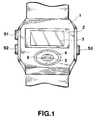
- Fig. 1 is a front view showing an external view of the electronic wrist watch to which the present invention is applied.
- a reference numeral 1 stands for a casing of the electronic wrist watch
- a reference numeral 2 stands for a watch glass
- a reference numeral 3 designates a liquid crystal display device
- a reference numeral 4 is a pulse detecting unit.
- the pulse detecting unit 4 optically senses a blood flow in a fingertip of a user, detecting the density of hemoglobin in blood, thereby detecting pulses.
- the pulse detecting unit 4 comprises a light emitting element (for example, a light emitting diode) 5 and a light receiving element (for example, a photo transistor) 6.
- the number of pulses is counted with the fingertip of the user being in contact with the pulse detecting unit 4.
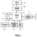
- Fig. 2 is the circuit diagram of the electronic watch.
- a control unit (CPU) 7 installed within the electronic wrist watch is a central processing unit which controls various units in accordance with a micro-program previously stored in a ROM 8, and performs various processes such as a time counting process, a pulse-number counting process and a calculating process of exercise hardness.
- a RAM 9 is a memory for storing various data, which will be described in detail later.
- a key input unit 10 is provided with the keys S1-S3 shown in Fig. 1, and outputs a key input signal in response to an actuation of the key.
- the key S1 is operated to renew a content of a mode register M, thereby an operation mode is changed.
- the key S2 is for inverting a content of a flag register F.
- the key S3 is for allowing other processes to be performed.
- a pulse detecting circuit 11 is connected with the light emitting element 5 and the light receiving element 6, which are included in the pulse detecting unit 4 shown in Fig. 1.
- the pulse detecting circuit 11 senses decreases in the intensity of light received by the light receiving element 6 from the light emitting element 5, caused by changes of a blood flow, thereby detecting pulses. Further, the pulse detecting circuit 11 outputs to a control unit (CPU) 7 a pulse signal which varies in synchronism with the detected pulses.
- a decoder driver 12 decodes display data supplied from the control unit 7, and supplies a display driving signal to a display unit 13.
- the display unit 13 is composed of the liquid crystal display device 3, and is driven by the display driving signal supplied from the decoder driver 12, thereby displaying various data. A detailed structure of the display unit 13 will be described later.
- An oscillation circuit 14 generates a clock signal of a predetermined frequency, and supplies the clock signal to a frequency divider/timing circuit 15.
- the frequency divider/timing circuit 15 divides the supplied clock signal to generated various timing signals such as a time counting signal, and supplies these timing signals to the control unit 7.
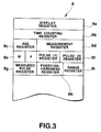
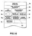
- Fig. 3 is a view showing the memory structure of the RAM 9.
- a display register 9a in the RAM 9 is a register for storing display data to be displayed on the display unit 13.
- a time counting register 9b is a register for storing a current time and a current date.
- An age register 9c is a register which stores age data of a user input from the key input unit 10.
- a measurement register 9d is a register for storing a time during which the user exercises.
- the mode register M is a register which stores mode data.
- the flag register F is a register which stores a flag representative of a time measuring state while the user is exercising.
- a pulse (1) register 9e is a register which stores pulse-number data corresponding to 60% (the lower limit of the most suitable pulse-number data) of the maximum pulse number.
- a pulse (2) register 9f is a register which stores pulse data corresponding to 80% (the upper limit of the most suitable pulse-number data) of the maximum pulse number.
- a measured pulse register 9g is a register which stores measured pulse-number data.
- An exercise hardness register 9h is a register for storing exercise hardness data which represents a ratio (%) of a measured pulse number to the maximum pulse number. The exercise hardness data is expressed in percent.
- a range register 9i is a register which stores range data which indicates whether or not a measured pulse number falls within a range of 60% to 80% of the maximum pulse number.
- a pulse number which falls within the range of 60% to 80% of the maximum pulse number is referred to as the most suitable pulse number.
- the range data takes three values: "0", "1” and "2".
- the range data "0” represents that a measured pulse number is the most suitable pulse number or the measured pulse number falls within the above mentioned range.
- the range data "1” represents that the measured pulse number is lower than the most suitable pulse number.
- the range data "2" represents that the measured pulse number is higher than the most suitable pulse number.
- the control unit 7 stays usually in a halt state, waiting for the time counting signal from the frequency divider/timing circuit 15 or for a key input of the key input unit 10 at step A1.
- the control unit 7 Upon receipt of the time counting signal, the control unit 7 advances from step A1 to step A2 to execute a time counting process. In the time counting process, present time data (including date, day of the week) stored in the time counting register 9b of the RAM 9 is updated.
- M 1
- the second numeral display portion 13b is displayed age data, " AGE 31" (the user is 31 years of age) stored in the age register 9c.
- the range of the most suitable pulse number is displayed at the pulse-number bar-graph display portion 13c. In other words, appropriate number of bars of the pulse-number bar-graph display portion 13c are kept turned on to indicate the most suitable pulse-number range.
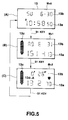
- Fig. 6 is a view showing a structure of the pulse-number bar-graph display portion 13c.
- the pulse-number bar-graph display portion 13c is composed of an upper limit indicating segment (A) of a triangle shape, 13 units of segments (B) of a rectangle shape for indicating a pulse-number range and a lower limit indicating segment (C) of a triangle shape.
- the segment (A) is arranged with the vertex disposed upward as viewed in Fig. 6 while the segment (C) is arranged with the vertex disposed downward.
- the pulse-number bar-graph display portion 13c schematically indicates a pulse-number range at the most suitable exercise load and a measured pulse number.
- the upper limit indicating segment (A) is turned on when a measured pulse number or the pulse-number range at the most suitable exercise load exceeds a pulse number "160".
- the segments (B) each indicate a pulse number "5" and are provided corresponding to pulse-number ranges such as "91-95”, “96-100”, ... , "151-155" and "156-160", printed on the display unit 13.
- the lower limit indicating segment (C) is turned on when a measured pulse number or the pulse-number range at the most suitable exercise load is not more than a pulse number "90".
- step A9 9 units of rectangle-shaped segments (B) of the pulse-number bar-graph display portion 13c, which correspond to pulse numbers from "151” to "113", are steadily turned on as shown at (B) in Fig. 5. Then, the control unit 7 returns from step A9 to step A1.
- Update of age data is effected by manipulating the key S2 while the indication shown at (B) of Fig. 5 is displayed on the display unit 13.
- the control unit 7 advances from step A1 to step A10.
- the control unit 7 judges "NO” at step A10, and advances to step A12. It is judged at step A12 whether the key S2 is manipulated. When “YES” at step A12, then the control unit 7 goes to step A13 while, 2) when "NO” at step A12, then the control unit goes to step A16.
- step A13 When “YES” at step A13, then the control unit 7 goes to step A14 while, when "NO” at step A13, then the control unit goes to step A17.
- "+1" is added to age data stored in the age register 9c, thereby the age data being updated.
- a most suitable pulse-number calculating process is effected.
- pulse numbers of 60% and 80% of the maximum pulse number for the user of the age are calculated based on the updated age, and the most suitable pulse-number range for the age is defined by these calculated pulse numbers: the lower limit of the most suitable pulse number and the upper limit of the most suitable pulse number.
- the pulse numbers of 60% of the maximum pulse number for the user of the age is stored in the pulse (1) register 9e and the pulse number of 80% of the maximum pulse number is stored in the pulse (2) register 9f.
- the pulse number "131" of 60% of the maximum pulse number (N-max) "189” is stored as the lower limit of the most suitable pulse number in the pulse (1) register 9e while the pulse number "151" of 80% of the maximum pulse number "189” is stored as the upper limit of the most suitable pulse number in the pulse (2) register 9f.
- the control unit 7 advances from step A15 to step A9.
- the upper limit and the lower limit of the most suitable pulse number and age data are displayed, and further the most suitable pulse-number range is displayed by the pulse-number bar-graph display portion 13c.
- the control unit 7 goes to step A18.
- the pulse measuring process is effected.
- the pulse detecting circuit 11 detects pulses by means of the light emitting element 5 and the light receiving element 6, and outputs the pulse signals to the control unit 7.
- the control unit 7 measures time intervals between successive pulse signals, i.e., pulse intervals to calculate the number of pulses per minute.
- Data of the pulse number per minute (pulse-number data) is stored in the measured pulse register 9g of the RAM 9. Since measurement of the number of pulses takes considerable time, it is judged at the following step A6 whether the pulse measurement process has been finished at step A5. When the pulse measurement process has not been finished, the control unit 7 returns through the display process of step A9 to step A1.
- the control unit 7 repeatedly executes processes of steps A1 to A5, thereby measuring pulse-number data (pulse number per minute), for example, "132", and stores the pulse-number data in the measured pulse register 9g, and then the control unit 7 returns from step A6 to step A7.
- pulse-number data pulse number per minute
- exercise hardness is calculated from the measured number of pulses.
- the exercise hardness is calculated from the measured pulse-number data and age data of a user.
- the upper limit of the maximum pulse number for people of 20 years of age is approximately 200 pulses/minute.
- the upper limit of the maximum pulse number for people of 40 years of age is approximately 180 pulses/minute.
- the upper limit of the maximum pulse number for people of 60 years of age is approximately 160 pulses/minute.
- the exercise hardness calculated from the above equation is stored in the exercise hardness register 9h of the RAM 9.
- the exercise hardness data stored in the exercise hardness register 9h represents a ratio expressed in percent of the measured pulse number to the maximum pulse number for the user of the age.
- the exercise hardness data is data representative of a ratio of exercise hardness of exercise which the user took to the maximum exercise hardness accomplished at the maximum pulse number for an age of the user.
- a range discriminating process is effected. In the range discriminating process at step A8, it is judged whether the measured pulse-number data "132" falls within a range of most suitable exercise load.
- the range discriminating process it is judged whether the measured pulse-number data falls within a range defined by 60% of the maximum exercise hardness and 80% of the maximum exercise hardness, which have been stored in the pulse (1) register 9e and the pulse (2) register 9f, respectively.
- a result of the discrimination is stored in the range register 9i.
- pulse-number data "113" corresponding to 60% of the maximum pulse number was stored in the pulse (1) register 9e when the age data was updated at step A15, and pulse-number data "151" corresponding to 80% of the maximum pulse number was stored in the pulse (2) register 9e.
- the content of the measured pulse register 9g is compared with those stored in the pulse (1) register 9e and the pulse (2) register 9e.
- the resultant "1" is stored in the range register.
- the resultant "0" is stored in the range register.
- the resultant "2" is stored in the range register. In this case, as the measured pulse-number data is "132", the resultant "0" is stored in the range register.
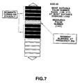
- Figs. 7 and 8 are views showing detailed examples of indications shown at the pulse-number bar-graph display portion 13c.
- Fig. 7 is a view of the pulse-number bar-graph display portion 13c which indicates age data "25", the most suitable pulse-number range "156-117” at the most suitable exercise load, and measured pulse-number data "140".
- 9 units of segments (B) for indicating a pulse-number range, which correspond to pulse numbers from “156” to "117”, are steadily turned on to indicate the most suitable pulse-number range "156-117”
- a segment (B) for indicating a pulse-number range, which corresponds to a pulse number "136-140” is turned on in a blinking manner at a frequency of 2 Hz.
- Fig. 8 is a view of the pulse-number bar-graph display portion 13c which indicates age data "20", the most suitable pulse-number range "160-120” at the most suitable exercise load, and measured pulse-number data "180".
- the upper limit indicating segment (A) is turned on in a blinking manner at a frequency of 2 Hz, and the segments (B) for indicating a pulse-number range, which correspond to pulse numbers from “160” to "120", are steadily turned on to indicate the most suitable pulse-number range "160-120".
- indicating segments are displayed at the exercise-hardness display portion 13d based on the resultant of the judgement stored in the range register 9i. More specifically, as shown in Fig. 9, indicating segments "U", “A” and “O” are disposed in a lateral direction at the exercise-hardness display portion 13d.
- the indicating segment “U” is turned on when measured pulse number is less than the most suitable pulse number at the most suitable exercise load.
- the indicating segment "A” is turned on when measured pulse number falls within the most suitable pulse-number range at the most suitable exercise load.
- the indicating segment "O” is turned on when measured pulse number is more than the most suitable pulse number at the most suitable exercise load.
- the control unit 7 returns to step A1.
- step A16 When a key other than S1 and S2 is manipulated, the control unit 7 goes to step A16 through step A12. At step A16, another key process is performed such as setting or correcting a present time, clearing various registers of the RAM 9. After step A16, the control unit 7 goes to step A9.
- the above mentioned exercise-hardness data are displayed for general purposes in the exercise physiology.
- the user can objectively learn from the displayed exercise-hardness data whether exercise taken by him (or her) is one he desired, and the user can effectively use these data for maintaining his health and/or developing his physical body.
- age data is set through the key input.
- the second embodiment is arranged such that birthday data of the user is previously memorised in a birthday memory and the age data is automatically updated when the memorized birthday data coincides with the present-date data. It should be noted that any structure which is not shown in Figs. 10 and 11 is the same as the first embodiment.
- Fig. 10 is a view showing a structure of a RAM 9 of the second embodiment of the present invention.
- the RAM 9 of the second embodiment includes a birthday memory 9j in addition to the registers of the RAM 9 of the first embodiment.
- the birthday memory 9j stores date data representative of a birthday of a user.
- the date data representative of the birthday of the user is hereafter referred to as birthday data.
- the birthday data is set in the birthday memory 9j in the another key process at step A16.
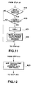
- the second embodiment executes four processes shown in a flowchart of Fig. 11 in addition to the processes of Fig. 4. Step A19 to step A22 of Fig. 11 are inserted into the flowchart of Fig. 4 between step A2 and step A3.
- step A19 it is judged whether the current time data stored in the time counting register 9b in the time counting process is updated.
- the control unit goes to step A20 while, when "NO” at step A19, then the control unit 7 goes to step A3 of Fig. 4.
- step A20 it is judged whether the current date data stored in the time counting register 9b coincides with the birthday data stored in the birthday memory 9j.
- the control unit goes to step A21 while, when "NO” at step A19, then the control unit 7 goes to step A3 of Fig. 4.
- step A20 When it is judged at step A20 whether the current date data coincides with the birthday data, the control unit 7 advances from step A20 to step A21.
- step A21 age data of the user stored in the age register 9c is added with +1, thereby being updated.
- step A22 the most suitable pulse-number is calculated in a similar manner to step A15 of Fig. 4. More specifically, in the most suitable pulse-number calculating process, a pulse number corresponding to 60% of the maximum pulse number (220 - age) for the user of the age is calculated and further a pulse number corresponding to 80% of the maximum pulse number (220 -age) is calculated, using the age data updated at step A21.
- the pulse number corresponding to 60% of the maximum pulse number is stored in the pulse (1) register 9e and the pulse number corresponding to 80% of the maximum pulse number is stored in the pulse (2) register 9f.
- the control unit 7 goes to step A3 of Fig. 4.
- the age updating process at step A14 of Fig. 4 can be omitted.
- a RAM 9 of the third embodiment similar to the RAM 9 of the second embodiment has a birthday memory 9j in addition to the registers of the RAM 9 of the first embodiment.
- the third embodiment is arranged such that age data is not previously stored in the age register 9c, but the age data is previously calculated every time the exercise-hardness calculation and the most suitable pulse-number calculation are performed.
- a step shown in Fig. 12 is added to the flowchart of Fig. 4. That is, the step A23 of Fig. 12 is performed in place of the age updating process at step A14 of Fig. 4.
- step A13 when the key S2 is manipulated, the control unit 7 advances from step A12 of Fig. 4 to step A13.
- age data of the user is calculated from current date data stored in the time counting register 9b and birthday data stored in the birthday memory 9j.
- the calculated age data is stored in the age register 9c of the RAM 9.
- step A15 of Fig. 4 the control unit goes to step A15 of Fig. 4, where it calculates the most suitable pulse number from the age data, as described above.
- the process at step A23 is added to the flowchart of Fig. 4 between step A6 and step A7. Therefore, when "YES" at step A6, the process at step A23 is executed, thereby age data being calculated. Then, the control unit 7 goes to step A7, where exercise-hardness data is calculated from the calculated age data.
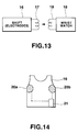
- the fourth embodiment detects an electrocardiogram R-wave of the user to measure the number of his (or her) pulses, with use of electrodes which are mounted on a shirt of the user.
- Fig. 13 is a block diagram showing a structure of an exercise-hardness display system in the fourth embodiment.
- the shirt 16 of the user is provided with an electronic circuit (to be described later) including a pair of electrodes for detecting an electrocardiogram R-wave and with a coil 17 for transmitting an electromagnetic inductive signal of the detected electrocardiogram R-wave.
- a wrist watch 18 is put on the arm of the user who wears the shirt 16.
- the wrist watch 18 is provided with a coil 19 for receiving from the coil 17 the electromagnetic inductive signal of the detected electrocardiogram R-wave.
- Fig. 14 is a view showing a structure of the shirt 16.
- the shirt 16 is, for example, of a running-shirt shape, on both side portions of which a pair of electrodes 20a, 20b are mounted, as shown in Fig. 14.
- the electrodes 20a, 20b are kept in contact with a body of the user who wears the shirt 16.
- the electrodes 20a, 20b detect the electrocardiogram R-wave generated by the heart of the user, and transmit the detected electrocardiogram R-wave to the electronic circuit 21.
- the electronic circuit 21 is mounted on a west portion of the shirt 16.
- the electronic circuit 21 externally transmits through the coil 17 the electromagnetic inductive signal of the received electrocardiogram R-wave.
- Fig. 15 is a block diagram showing of the electronic circuit 21 mounted on the shirt 16.
- the pair of electrodes 20a, 20b for detecting an electrocardiogram R-wave are connected to a detecting circuit 22 to transmit the detected electrocardiogram R-wave thereto.
- the detecting circuit 22 amplifies the received electrocardiogram R-wave and supplies it to a transmitting circuit 23.
- the transmitting circuit 23 converts the electrocardiogram R-wave received from the detecting circuit 22 into an electromagnetic inductive signal, and send it to the coil 17.
- the electromagnetic inductive signal sent from the coil 17 can be well detected at a distance of approximately 2 meters from the coil 17.
- a power circuit 23 includes, for example, a battery, and supplies a driving voltage through a power switch 25 to the detecting circuit 15 and the transmitting circuit 23.
- Fig. 16 is a block diagram of a circuitry mounted in the wrist watch 18.
- the receiving circuit 26 receives the electrocardiogram R-wave from the coil 19, and transmits the same to a waveform-shaping circuit 27.
- the waveform-shaping circuit 27 shapes the waveform of the electrocardiogram R-wave transmitted from the receiving circuit 26, and supplies the electrocardiogram R-wave to a control unit 28.
- the receiving circuit 26 and the waveform-shaping circuit 27 start operations in response to an operation signal supplied from the control unit 28.
- the control unit 28 is a central processing unit, which controls operations of peripheral units in accordance with a micro-program previously memorized in a ROM 29.
- the ROM 30 is a memory for storing various data.
- a decoder driving circuit 31 outputs to a display unit 32 a display driving signal based on display data output from the control unit 28, thereby driving the display unit 32.
- the display unit 32 having liquid crystal display elements, displays a present time, the number of pulses and the like.
- a key input unit 33 is provided with the keys S1 to S3, and outputs a key input signal responsive to a key input operation to the control unit 28.
- An oscillator circuit 34 generates a clock signal of a predetermined frequency, and outputs the clock signal to a frequency dividing/timing circuit 35.
- the frequency dividing/timing circuit 35 divides the clock signal sent from the oscillator circuit 34 to generate various timing signals such as a time counting signal. The timing signals are supplied to the control unit 28.
- the operation of the fourth embodiment is the same as the first embodiment as illustrated in Figs. 3-9, with exception of the pulse detecting process, and the description thereof is omitted.
- the electrocardiogram R-wave is transmitted and received electromagnetic inductively, but the transmission of an electromagnetic wave of the electrocardiogram R-wave may be executed with use of a transmitting device and an antenna.
- the fifth embodiment is arranged such that the user can arbitrarily set a pulse number at the most suitable exercise hardness depending on his physical condition.
- the user can use the apparatus of the fifth embodiment in various ways. For example, when the user takes some exercise after he recovers his health, he can set a suitable pulse number for the most suitable exercise hardness to low levels such as 55% to 65% of the maximum pulse number, and gradually raises the exercise load to recover his physical strength in an appropriate manner. For the user who has well trained, the pulse number can be set to high levels (a training zone): 80% to 90% of the maximum pulse number for the most suitable exercise hardness to greatly develop his physical strength.
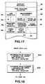
- Fig. 17 is a view showing a memory structure of the RAM 9 of the fifth embodiment.
- the memory structure of the RAM 9 in the fifth embodiment has a similar structure to the RAM 9 of the first embodiment, but is further provided with an upper limit register 9l and a lower limit register 9k.
- the upper limit register 9l is for storing an upper limit percentage value of the exercise hardness.
- the lower limit register 9k is for storing a lower limit percentage value of the exercise hardness.
- the key S3 is manipulated to set a range setting mode. Then, the upper limit percentage value can be set to the upper limit register 9l, by manipulating the key S1 while the lower limit percentage value can be set to the lower limit register 9k by manipulating the key S2.
- step A24 and A25 shown in Fig. 18 are added to the flowchart of Fig. 4 in place of the step A15.
- the control unit 28 goes to step A24 of Fig. 18.
- an arithmetic operation (the maximum pulse number for the age of the user) X (a value (%) of the lower limit register 9k).
- the resultant product (the lower limit of the most suitable pulse number) is stored in the pulse (1) register 9e.
- the resultant product (the upper limit of the most suitable pulse number) is stored in the pulse (2) register 9f.
- step A25 the control unit 28 goes to step A9 of Fig. 4.
- the most suitable pulse number is calculated based on the upper limit percentage value and the lower limit percentage value, which have been arbitrarily set by the user.
- the most suitable pulse-number range for the most suitable exercise hardness is set to 60% to 80% of the maximum pulse number, but the range is not always limited to these values.
- a pulse number corresponding to 75% of the maximum pulse number may be calculated and displayed as a target pulse number.
- the maximum pulse number is calculated from the expression: "220 - AGE", but the maximum pulse numbers for respective ages of users may be previously memorized in a memory such as a ROM and are read out therefrom every time an arithmetic operation is performed.
- Pulses are detected and measured by methods other than in the above embodiments. For example, sounds and pressure may be used to detect or measure pulses.
- the pulse measuring process is effected while the user is taking exercise, but the pulse measuring process may be effected when the time counting process is stopped.
- the apparatus according to the present invention is applied to the electronic wrist watch, but the apparatus may be applied to other electronic appliances, for example, a training instrument such as an ergometer and an instrument specialized for measuring pulses, which will be prepared for exerciser convenience at a training center.
- the obtained exercise-hardness data is displayed on the liquid crystal display unit of the electronic wrist watch.
- the obtained exercise-hardness data may be transmitted to a separate appliance, or may be printed by a printing device mounted on the apparatus body or by a separate printer.
Abstract
Description
- The present invention relates to an exercise- hardness data output apparatus which counts the number of pulses of a user and outputs data representative of exercise hardness based on the counted number of pulses.
- In general, it is well known that physical exercise increases the number of pulses of an exerciser in proportion to the physical exercise hardness attained by his (or her). Comparison of the number of pulses of the exerciser which is counted immediately after the exerciser has finished exercise with the number of pulses of the exerciser which was counted just before the exerciser started the exercise will indicate exercise hardness attained by the exerciser. Such technique is disclosed in U.S. Patent No. 4,807,639.
- The above conventional technique, however, has problems such that the number of pulses of an exerciser does not indicate whether exercise hardness attained by the exerciser is enough or appropriate for maintaining him (or her) healthy, whether the exercise hardness is satisfactory not only to keep his physical strength but also to develop his physical strength or whether or not an excessive exercise hardness has been attained by the exerciser.
- The present invention has been made to overcome the above conventional problems, and has an object to provide an exercise-hardness data output apparatus that is capable of outputting exercise-hardness data which can be used for general purposes of exercise physiology.
- Another object of the present invention is to provide an exercise-hardness data output apparatus which is capable of objectively indicating exercise hardness achieved by an exerciser, and which can be conveniently used by the exerciser for the purpose of maintaining him (or her) healthy or developing his physical strength.
- To achieve these objects of the present invention, there is provided an exercise-hardness data output apparatus which comprises:
age-data output means for outputting age data;
pulse-number counting means for counting pulses of a user to obtain pulse-number data;
exercise-hardness calculating means for calculating exercise-hardness data from the pulse-number data obtained by said pulse-number counting means and the age data output by said age-data output means; and
output means for outputting the exercise-hardness data calculated by said exercise-hardness calculating means. - The above output means is transmitting/outputting means which externally supplies the exercise-hardness data calculated by the exercise-hardness calculating means. That is, the output means includes displaying/outputting means such as a liquid crystal display device for visually displaying the exercise-hardness data and printing/outputting means for printing the exercise-hardness data to make a hard copy.
- With the above structure of the exercise-hardness data output apparatus, exercise-hardness data is calculated from the pulse-number data representative of the counted number of pulses of the user and the age data, and the calculated exercise-hardness data is output. The exercise-hardness data thus obtained therefore is output as data that may be used for general purposes of the exercise physiology. Further, the exercise-hardness may objectively be measured by the exercise-hardness data output apparatus of the invention and may be used for maintaining the user healthy and/or for developing physical strength of the user.
- Fig. 1 is a front view showing an external view of a first embodiment of an electronic watch according to the present invention;
- Fig. 2 is a circuit diagram of the electronic watch;
- Fig. 3 is a view showing a memory structure of
RAM 9 of Fig. 2; - Fig. 4 is a flow chart of operation of the first embodiment;
- Fig. 5 is a view showing indications in various modes;
- Fig. 6 is a view showing a structure of a pulse-number bar-
graph display portion 13c; - Fig. 7 is a view showing an indication on the pulse-number bar-
graph display portion 13c; - Fig. 8 is a view showing another indication on the pulse-number bar-
graph display portion 13c; - Fig. 9 is a view showing a structure of an exercise-
hardness display portion 13d; - Fig. 10 is a view showing a memory structure of
RAM 9 of a second embodiment of the present invention; - Fig. 11 is a flow chart of operation of the second embodiment;
- Fig. 12 is a flow chart of operation of a third embodiment of the present invention;
- Fig. 13 is a block diagram showing a structure of an exercise-hardness display system of a fourth embodiment of the present invention;
- Fig. 14 is a view showing a structure of a
shirt 16 of the fourth embodiment; - Fig. 15 is a circuit diagram of an
electronic circuit 21 of the fourth embodiment; - Fig. 16 is a circuit diagram of a
wrist watch 18 of the fourth embodiment; - Fig. 17 is a view showing a memory structure of
RAM 9 of a fifth embodiment of the present invention; and - Fig. 18 is a flow chart of operation of the fifth embodiment.
- Now, the first embodiment of the present invention will be described in detail with reference to the accompanying drawings.
- In the first embodiment, the present invention is applied to an electronic wrist watch.
- Fig. 1 is a front view showing an external view of the electronic wrist watch to which the present invention is applied. In Fig. 1, a
reference numeral 1 stands for a casing of the electronic wrist watch, areference numeral 2 stands for a watch glass, areference numeral 3 designates a liquid crystal display device and areference numeral 4 is a pulse detecting unit. Thepulse detecting unit 4 optically senses a blood flow in a fingertip of a user, detecting the density of hemoglobin in blood, thereby detecting pulses. Thepulse detecting unit 4 comprises a light emitting element (for example, a light emitting diode) 5 and a light receiving element (for example, a photo transistor) 6. The number of pulses is counted with the fingertip of the user being in contact with thepulse detecting unit 4. On a side wall of thewatch casing 1 are arranged keys of a push button type S1-S3. - Fig. 2 is the circuit diagram of the electronic watch. A control unit (CPU) 7 installed within the electronic wrist watch is a central processing unit which controls various units in accordance with a micro-program previously stored in a
ROM 8, and performs various processes such as a time counting process, a pulse-number counting process and a calculating process of exercise hardness. ARAM 9 is a memory for storing various data, which will be described in detail later. Akey input unit 10 is provided with the keys S1-S3 shown in Fig. 1, and outputs a key input signal in response to an actuation of the key. The key S1 is operated to renew a content of a mode register M, thereby an operation mode is changed. The key S2 is for inverting a content of a flag register F. The key S3 is for allowing other processes to be performed. - A
pulse detecting circuit 11 is connected with thelight emitting element 5 and thelight receiving element 6, which are included in thepulse detecting unit 4 shown in Fig. 1. Thepulse detecting circuit 11 senses decreases in the intensity of light received by thelight receiving element 6 from thelight emitting element 5, caused by changes of a blood flow, thereby detecting pulses. Further, thepulse detecting circuit 11 outputs to a control unit (CPU) 7 a pulse signal which varies in synchronism with the detected pulses. Adecoder driver 12 decodes display data supplied from thecontrol unit 7, and supplies a display driving signal to adisplay unit 13. - The
display unit 13 is composed of the liquidcrystal display device 3, and is driven by the display driving signal supplied from thedecoder driver 12, thereby displaying various data. A detailed structure of thedisplay unit 13 will be described later. Anoscillation circuit 14 generates a clock signal of a predetermined frequency, and supplies the clock signal to a frequency divider/timing circuit 15. The frequency divider/timing circuit 15 divides the supplied clock signal to generated various timing signals such as a time counting signal, and supplies these timing signals to thecontrol unit 7. - Fig. 3 is a view showing the memory structure of the
RAM 9. - A
display register 9a in theRAM 9 is a register for storing display data to be displayed on thedisplay unit 13. Atime counting register 9b is a register for storing a current time and a current date. Anage register 9c is a register which stores age data of a user input from thekey input unit 10. Ameasurement register 9d is a register for storing a time during which the user exercises. - The mode register M is a register which stores mode data. The mode data "M = 0" represents a time display mode in which a time is displayed has been set. The mode data "M = 1" represents an age setting mode in which an age has been set and the pulse data most suitable for the age is displayed. The mode data "M = 2" represents a pulse measuring mode in which a time counting process is performed, a pulse is displayed and exercise hardness is displayed.
- The flag register F is a register which stores a flag representative of a time measuring state while the user is exercising. The flag "F = 1" represents that a time counting process is being effected. A pulse (1)
register 9e is a register which stores pulse-number data corresponding to 60% (the lower limit of the most suitable pulse-number data) of the maximum pulse number. A pulse (2)register 9f is a register which stores pulse data corresponding to 80% (the upper limit of the most suitable pulse-number data) of the maximum pulse number. A measuredpulse register 9g is a register which stores measured pulse-number data. Anexercise hardness register 9h is a register for storing exercise hardness data which represents a ratio (%) of a measured pulse number to the maximum pulse number. The exercise hardness data is expressed in percent. - A
range register 9i is a register which stores range data which indicates whether or not a measured pulse number falls within a range of 60% to 80% of the maximum pulse number. Hereafter, a pulse number which falls within the range of 60% to 80% of the maximum pulse number is referred to as the most suitable pulse number. The range data takes three values: "0", "1" and "2". The range data "0" represents that a measured pulse number is the most suitable pulse number or the measured pulse number falls within the above mentioned range. The range data "1" represents that the measured pulse number is lower than the most suitable pulse number. The range data "2" represents that the measured pulse number is higher than the most suitable pulse number. - The operation of the first embodiment of the present invention will be described referring to the flow chart of Fig. 4.
- The
control unit 7 stays usually in a halt state, waiting for the time counting signal from the frequency divider/timing circuit 15 or for a key input of thekey input unit 10 at step A1. - Upon receipt of the time counting signal, the
control unit 7 advances from step A1 to step A2 to execute a time counting process. In the time counting process, present time data (including date, day of the week) stored in thetime counting register 9b of theRAM 9 is updated. At step A3, thecontrol unit 7 judges whether "M = 2" and "F = 1" are true. More specifically, the control unit judges whether or not the content of the mode register M is "2" (the pulse measuring mode) and the content of the flag register F is "1" (under time counting process). When "YES" at step A3, thecontrol unit 7 goes to step A4 and when "NO" at step A3, then thecontrol unit 7 goes to step A9. - When "M = 0" is true, i.e., when the time display mode has been set, the
control unit 7 judges "NO" at step A3 and goes to step A9. In the display mode at step A9, a pertinent indication is displayed. That is, when "M = 0" is true, current time data stored in thetime counting register 9b is displayed as shown at (A) in Fig. 5. At a firstnumeral display portion 13a of thedisplay unit 13, current time data: "10 : 58 50" (58 minutes and 50 seconds past 10 o'clock) is displayed. At a secondnumeral display portion 13b, week data: "SU" (Sunday) and date data: "6-30" (June 30) are displayed. Then thecontrol unit 7 returns from step A9 to step A1. - When the key S1 is manipulated while the indication shown at (A) of Fig. 5 is displayed on the
display unit 13, the operation mode is changed. That is, receiving the key input from thekey input unit 10, thecontrol unit 7 advances from step A1 to step A10, where it is judged whether the key S1 is manipulated. When "YES" at step A10, thecontrol unit 7 goes to step A11. When "NO" at step A10, thecontrol unit 7 goes to A12. At step A11, the content of the mode register M is updated, i.e., form "0" to "1", from "1" to "2" or from "2" to "0". When the key S1 is manipulated in the time display mode (M = 0), "M = 0" is updated to "M = 1" (the age setting mode) at step A11. Then, thecontrol unit 7 advances from step A11 to step A9. - At step A9, based on the contents of the pulse (1)
register 9e and the pulse (2)register 9f, the lower limit and the upper limit of the most suitable pulse-number data, for example "151 - 113", are displayed at the firstnumeral display portion 13a in the age setting mode ("M = 1"), as shown at (B) in Fig. 5. At the secondnumeral display portion 13b is displayed age data, "AGE 31" (the user is 31 years of age) stored in theage register 9c. The range of the most suitable pulse number is displayed at the pulse-number bar-graph display portion 13c. In other words, appropriate number of bars of the pulse-number bar-graph display portion 13c are kept turned on to indicate the most suitable pulse-number range. - Fig. 6 is a view showing a structure of the pulse-number bar-
graph display portion 13c. - As shown in Fig. 6, the pulse-number bar-
graph display portion 13c is composed of an upper limit indicating segment (A) of a triangle shape, 13 units of segments (B) of a rectangle shape for indicating a pulse-number range and a lower limit indicating segment (C) of a triangle shape. The segment (A) is arranged with the vertex disposed upward as viewed in Fig. 6 while the segment (C) is arranged with the vertex disposed downward. The pulse-number bar-graph display portion 13c schematically indicates a pulse-number range at the most suitable exercise load and a measured pulse number. The upper limit indicating segment (A) is turned on when a measured pulse number or the pulse-number range at the most suitable exercise load exceeds a pulse number "160". The segments (B) each indicate a pulse number "5" and are provided corresponding to pulse-number ranges such as "91-95", "96-100", ... , "151-155" and "156-160", printed on thedisplay unit 13. The lower limit indicating segment (C) is turned on when a measured pulse number or the pulse-number range at the most suitable exercise load is not more than a pulse number "90". - In the display process at step A9, therefore, 9 units of rectangle-shaped segments (B) of the pulse-number bar-
graph display portion 13c, which correspond to pulse numbers from "151" to "113", are steadily turned on as shown at (B) in Fig. 5. Then, thecontrol unit 7 returns from step A9 to step A1. - Update of age data is effected by manipulating the key S2 while the indication shown at (B) of Fig. 5 is displayed on the
display unit 13. When the key S2 is manipulated, thecontrol unit 7 advances from step A1 to step A10. Thecontrol unit 7 judges "NO" at step A10, and advances to step A12. It is judged at step A12 whether the key S2 is manipulated. When "YES" at step A12, then thecontrol unit 7 goes to step A13 while, 2) when "NO" at step A12, then the control unit goes to step A16. - When it is judged at step A12 that the key S2 has been manipulated, the
control unit 7 goes to step A13, where it is judged whether "M = 1" is true, i.e., it is judged whether the age setting mode has been set. When "YES" at step A13, then thecontrol unit 7 goes to step A14 while, when "NO" at step A13, then the control unit goes to step A17. - When "M = 1" is true, i.e., when the age setting mode has been set, the
control unit 7 goes to step A14, where an age updating process is effected. In the age updating process at step A14, "+1" is added to age data stored in theage register 9c, thereby the age data being updated. At the following step A15, a most suitable pulse-number calculating process is effected. In the most suitable pulse-number calculating process at step A15, pulse numbers of 60% and 80% of the maximum pulse number for the user of the age are calculated based on the updated age, and the most suitable pulse-number range for the age is defined by these calculated pulse numbers: the lower limit of the most suitable pulse number and the upper limit of the most suitable pulse number. The pulse numbers of 60% of the maximum pulse number for the user of the age is stored in the pulse (1)register 9e and the pulse number of 80% of the maximum pulse number is stored in the pulse (2)register 9f. For example, when the age data is "31", the maximum pulse number N-max for the age "31" can be calculated from the following equation: N-max = 220 - 31, as will be described later. The pulse number "131" of 60% of the maximum pulse number (N-max) "189" is stored as the lower limit of the most suitable pulse number in the pulse (1)register 9e while the pulse number "151" of 80% of the maximum pulse number "189" is stored as the upper limit of the most suitable pulse number in the pulse (2)register 9f. Then, thecontrol unit 7 advances from step A15 to step A9. Similarly, at step A15, the upper limit and the lower limit of the most suitable pulse number and age data are displayed, and further the most suitable pulse-number range is displayed by the pulse-number bar-graph display portion 13c. - When "NO" at step A13, then the
control unit 7 goes to step A17. It is judges at step A17 whether "M = 2" is true, i.e., whether the pulse measuring mode has been set. When "YES" at step A17, then thecontrol unit 7 goes to step A18 while, when "NO" at step A17, then thecontrol unit 7 goes to step A9. When the pulse measuring mode has been set, i.e., when "M = 2" is true, thecontrol unit 7 goes to step A18. At step A18, the content of the flag register F is inverted, thereby "0" being changed to "1" or "1" to "0". In other words, when the key S2 is manipulated in the pulse measuring mode (M = 2), the content of the flag register F is inverted. After the process at step A18 has been executed, thecontrol unit 7 goes to step A9. - When the time counting signal is output while "M = 2" and "F = 1" are true, processes at steps A1 to A3 will be executed. When "YES" at step A3, the control unit goes to step A4. When "M = 2" and "F = 1" are true, the pulse measuring mode has been set and the time counting process is going on. The time counting process is effected at step A4. More specifically, time counting data stored in the
measurement register 9d ofRAM 9 is updated and time during which the user is exercising is measured. - At step A5, the pulse measuring process is effected. During the pulse measuring process, when a fingertip of the user is placed on the
pulse detecting unit 4, thepulse detecting circuit 11 detects pulses by means of thelight emitting element 5 and thelight receiving element 6, and outputs the pulse signals to thecontrol unit 7. Thecontrol unit 7 measures time intervals between successive pulse signals, i.e., pulse intervals to calculate the number of pulses per minute. Data of the pulse number per minute (pulse-number data) is stored in the measuredpulse register 9g of theRAM 9. Since measurement of the number of pulses takes considerable time, it is judged at the following step A6 whether the pulse measurement process has been finished at step A5. When the pulse measurement process has not been finished, thecontrol unit 7 returns through the display process of step A9 to step A1. - The
control unit 7 repeatedly executes processes of steps A1 to A5, thereby measuring pulse-number data (pulse number per minute), for example, "132", and stores the pulse-number data in the measuredpulse register 9g, and then thecontrol unit 7 returns from step A6 to step A7. - In an exercise-hardness calculating process at step A7, exercise hardness is calculated from the measured number of pulses. The exercise hardness is calculated from the measured pulse-number data and age data of a user.
- Statistical data of people show as follows:
- The upper limit of the maximum pulse number for people of 20 years of age is approximately 200 pulses/minute. The upper limit of the maximum pulse number for people of 40 years of age is approximately 180 pulses/minute. The upper limit of the maximum pulse number for people of 60 years of age is approximately 160 pulses/minute.
- From the above data, the maximum pulse number Y for the use of X years of age will be expressed by the following equation:

- At the step A7, the
control unit 7 calculates exercise hardness, by performing an arithmetic operation:
exercise hardness register 9h of theRAM 9. The exercise hardness data stored in theexercise hardness register 9h represents a ratio expressed in percent of the measured pulse number to the maximum pulse number for the user of the age. In other words, the exercise hardness data is data representative of a ratio of exercise hardness of exercise which the user took to the maximum exercise hardness accomplished at the maximum pulse number for an age of the user. In this case, as the age is "31", the maximum pulse number "189" will be obtained as follows: 220 - 31 = 189, and, as the measured pulse-number data is "132", the exercise hardness data will be "70" % (132/189X 100 ≐ 70 (%)), which is stored in the exercise-hardness register 9h. - At step A8, a range discriminating process is effected. In the range discriminating process at step A8, it is judged whether the measured pulse-number data "132" falls within a range of most suitable exercise load.
- In general, it is said that 60% to 80% of the maximum exercise hardness is the most suitable exercise load, and is most suitable exercise hardness for a human body in the exercise physiology. In the range discriminating process, it is judged whether the measured pulse-number data falls within a range defined by 60% of the maximum exercise hardness and 80% of the maximum exercise hardness, which have been stored in the pulse (1)
register 9e and the pulse (2)register 9f, respectively. A result of the discrimination is stored in therange register 9i. In this case, pulse-number data "113" corresponding to 60% of the maximum pulse number was stored in the pulse (1)register 9e when the age data was updated at step A15, and pulse-number data "151" corresponding to 80% of the maximum pulse number was stored in the pulse (2)register 9e. Therefore, the content of the measuredpulse register 9g is compared with those stored in the pulse (1)register 9e and the pulse (2)register 9e. When the measured pulse-number data is less than the most suitable exercise load, the resultant "1" is stored in the range register. When the measured pulse-number data is within the range of the most suitable exercise load, the resultant "0" is stored in the range register. When the measured pulse-number data is more than the most suitable exercise load, the resultant "2" is stored in the range register. In this case, as the measured pulse-number data is "132", the resultant "0" is stored in the range register. - At step A9, when "M = 2" is true, i.e., when the pulse measuring mode has been set, the measured pulse-number data "132" and the exercise-hardness data "70"% are displayed at the first
numeral display portion 13a, and time counting data "0' 26" (0 minute and 26 seconds) is displayed at the secondnumeral display portion 13b, as shown at (C) in Fig. 5. At the pulse-number bar-graph display portion - Figs. 7 and 8 are views showing detailed examples of indications shown at the pulse-number bar-
graph display portion 13c. - Fig. 7 is a view of the pulse-number bar-
graph display portion 13c which indicates age data "25", the most suitable pulse-number range "156-117" at the most suitable exercise load, and measured pulse-number data "140". 9 units of segments (B) for indicating a pulse-number range, which correspond to pulse numbers from "156" to "117", are steadily turned on to indicate the most suitable pulse-number range "156-117", and a segment (B) for indicating a pulse-number range, which corresponds to a pulse number "136-140", is turned on in a blinking manner at a frequency of 2 Hz. - Fig. 8 is a view of the pulse-number bar-
graph display portion 13c which indicates age data "20", the most suitable pulse-number range "160-120" at the most suitable exercise load, and measured pulse-number data "180". As the measured pulse-number data is more than "160", the upper limit indicating segment (A) is turned on in a blinking manner at a frequency of 2 Hz, and the segments (B) for indicating a pulse-number range, which correspond to pulse numbers from "160" to "120", are steadily turned on to indicate the most suitable pulse-number range "160-120". - Returning to (C) of Fig. 5 , indicating segments are displayed at the exercise-
hardness display portion 13d based on the resultant of the judgement stored in therange register 9i. More specifically, as shown in Fig. 9, indicating segments "U", "A" and "O" are disposed in a lateral direction at the exercise-hardness display portion 13d. The indicating segment "U" is turned on when measured pulse number is less than the most suitable pulse number at the most suitable exercise load. The indicating segment "A" is turned on when measured pulse number falls within the most suitable pulse-number range at the most suitable exercise load. Further, the indicating segment "O" is turned on when measured pulse number is more than the most suitable pulse number at the most suitable exercise load. In this case, as the resultant of the judgement "0" is stored in therange register 9i, the indicating segment "A" is turned on. Returning to Fig. 4, after the display process at step A9 has been performed, thecontrol unit 7 returns to step A1. - When a key other than S1 and S2 is manipulated, the
control unit 7 goes to step A16 through step A12. At step A16, another key process is performed such as setting or correcting a present time, clearing various registers of theRAM 9. After step A16, thecontrol unit 7 goes to step A9. - In the present embodiment, the above mentioned exercise-hardness data are displayed for general purposes in the exercise physiology. The user can objectively learn from the displayed exercise-hardness data whether exercise taken by him (or her) is one he desired, and the user can effectively use these data for maintaining his health and/or developing his physical body.
- Now, the second embodiment of the present invention will be described with reference to Figs. 10 and 11.
- In the first embodiment of the invention, age data is set through the key input. The second embodiment, however, is arranged such that birthday data of the user is previously memorised in a birthday memory and the age data is automatically updated when the memorized birthday data coincides with the present-date data. It should be noted that any structure which is not shown in Figs. 10 and 11 is the same as the first embodiment.
- Fig. 10 is a view showing a structure of a
RAM 9 of the second embodiment of the present invention. - The
RAM 9 of the second embodiment includes abirthday memory 9j in addition to the registers of theRAM 9 of the first embodiment. Thebirthday memory 9j stores date data representative of a birthday of a user. The date data representative of the birthday of the user is hereafter referred to as birthday data. - The birthday data is set in the
birthday memory 9j in the another key process at step A16. The second embodiment executes four processes shown in a flowchart of Fig. 11 in addition to the processes of Fig. 4. Step A19 to step A22 of Fig. 11 are inserted into the flowchart of Fig. 4 between step A2 and step A3. - An operation of the second embodiment will be described.
- When the process at step A2 of Fig. 4 has been finished, the
control unit 7 goes to step A19 of Fig. 11. At step A19, it is judged whether the current time data stored in thetime counting register 9b in the time counting process is updated. When "YES" at step A19, the control unit goes to step A20 while, when "NO" at step A19, then thecontrol unit 7 goes to step A3 of Fig. 4. - When the current date data is updated, the
control unit 7 advances from step A19 to step A20. At step A20, it is judged whether the current date data stored in thetime counting register 9b coincides with the birthday data stored in thebirthday memory 9j. When "YES" at step A20, the control unit goes to step A21 while, when "NO" at step A19, then thecontrol unit 7 goes to step A3 of Fig. 4. - When it is judged at step A20 whether the current date data coincides with the birthday data, the
control unit 7 advances from step A20 to step A21. At step A21, age data of the user stored in theage register 9c is added with +1, thereby being updated. At the following step A22, the most suitable pulse-number is calculated in a similar manner to step A15 of Fig. 4. More specifically, in the most suitable pulse-number calculating process, a pulse number corresponding to 60% of the maximum pulse number (220 - age) for the user of the age is calculated and further a pulse number corresponding to 80% of the maximum pulse number (220 -age) is calculated, using the age data updated at step A21. The pulse number corresponding to 60% of the maximum pulse number is stored in the pulse (1)register 9e and the pulse number corresponding to 80% of the maximum pulse number is stored in the pulse (2)register 9f. After the process at step A22 has been finished, thecontrol unit 7 goes to step A3 of Fig. 4. - As described above, since age data of the user stored in the
RAM 9 is automatically updated in the second embodiment, the age updating process at step A14 of Fig. 4 can be omitted. - The third embodiment of the present invention will be described with reference to Fig. 12. A
RAM 9 of the third embodiment similar to theRAM 9 of the second embodiment has abirthday memory 9j in addition to the registers of theRAM 9 of the first embodiment. The third embodiment is arranged such that age data is not previously stored in theage register 9c, but the age data is previously calculated every time the exercise-hardness calculation and the most suitable pulse-number calculation are performed. - In the third embodiment, a step shown in Fig. 12 is added to the flowchart of Fig. 4. That is, the step A23 of Fig. 12 is performed in place of the age updating process at step A14 of Fig. 4.
- Now, an operation of the third embodiment will be described in detail.
- In the age setting mode (M = 1), when the key S2 is manipulated, the
control unit 7 advances from step A12 of Fig. 4 to step A13. Thecontrol unit 7 judges at step A13 that "M = 1" is true, and goes to step A23 of Fig. 12. At step A23 of Fig. 12, age data of the user is calculated from current date data stored in thetime counting register 9b and birthday data stored in thebirthday memory 9j. The calculated age data is stored in theage register 9c of theRAM 9. After step A23, the control unit goes to step A15 of Fig. 4, where it calculates the most suitable pulse number from the age data, as described above. - In the third embodiment, the process at step A23 is added to the flowchart of Fig. 4 between step A6 and step A7. Therefore, when "YES" at step A6, the process at step A23 is executed, thereby age data being calculated. Then, the
control unit 7 goes to step A7, where exercise-hardness data is calculated from the calculated age data. - The fourth embodiment of the present invention will be described with reference to Figs. 13-16.
- The fourth embodiment detects an electrocardiogram R-wave of the user to measure the number of his (or her) pulses, with use of electrodes which are mounted on a shirt of the user.
- Fig. 13 is a block diagram showing a structure of an exercise-hardness display system in the fourth embodiment.
- The
shirt 16 of the user is provided with an electronic circuit (to be described later) including a pair of electrodes for detecting an electrocardiogram R-wave and with acoil 17 for transmitting an electromagnetic inductive signal of the detected electrocardiogram R-wave. - A
wrist watch 18 is put on the arm of the user who wears theshirt 16. The wrist watch 18 is provided with acoil 19 for receiving from thecoil 17 the electromagnetic inductive signal of the detected electrocardiogram R-wave. - Fig. 14 is a view showing a structure of the
shirt 16. - The
shirt 16 is, for example, of a running-shirt shape, on both side portions of which a pair ofelectrodes electrodes shirt 16. Theelectrodes electronic circuit 21. Theelectronic circuit 21 is mounted on a west portion of theshirt 16. Theelectronic circuit 21 externally transmits through thecoil 17 the electromagnetic inductive signal of the received electrocardiogram R-wave. - Fig. 15 is a block diagram showing of the
electronic circuit 21 mounted on theshirt 16. - The pair of
electrodes circuit 22 to transmit the detected electrocardiogram R-wave thereto. The detectingcircuit 22 amplifies the received electrocardiogram R-wave and supplies it to a transmittingcircuit 23. The transmittingcircuit 23 converts the electrocardiogram R-wave received from the detectingcircuit 22 into an electromagnetic inductive signal, and send it to thecoil 17. The electromagnetic inductive signal sent from thecoil 17 can be well detected at a distance of approximately 2 meters from thecoil 17. Apower circuit 23 includes, for example, a battery, and supplies a driving voltage through apower switch 25 to the detectingcircuit 15 and the transmittingcircuit 23. - Fig. 16 is a block diagram of a circuitry mounted in the
wrist watch 18. - The
coil 19, which is connected to a receivingcircuit 26, receives the electromagnetic inductive signal of the electrocardiogram R-wave transmitted from thecoil 17. The receivingcircuit 26 receives the electrocardiogram R-wave from thecoil 19, and transmits the same to a waveform-shapingcircuit 27. The waveform-shapingcircuit 27 shapes the waveform of the electrocardiogram R-wave transmitted from the receivingcircuit 26, and supplies the electrocardiogram R-wave to acontrol unit 28. The receivingcircuit 26 and the waveform-shapingcircuit 27 start operations in response to an operation signal supplied from thecontrol unit 28. - The
control unit 28 is a central processing unit, which controls operations of peripheral units in accordance with a micro-program previously memorized in aROM 29. TheROM 30 is a memory for storing various data. Adecoder driving circuit 31 outputs to a display unit 32 a display driving signal based on display data output from thecontrol unit 28, thereby driving thedisplay unit 32. Thedisplay unit 32, having liquid crystal display elements, displays a present time, the number of pulses and the like. - A
key input unit 33 is provided with the keys S1 to S3, and outputs a key input signal responsive to a key input operation to thecontrol unit 28. Anoscillator circuit 34 generates a clock signal of a predetermined frequency, and outputs the clock signal to a frequency dividing/timing circuit 35. The frequency dividing/timing circuit 35 divides the clock signal sent from theoscillator circuit 34 to generate various timing signals such as a time counting signal. The timing signals are supplied to thecontrol unit 28. - The operation of the fourth embodiment is the same as the first embodiment as illustrated in Figs. 3-9, with exception of the pulse detecting process, and the description thereof is omitted. In the fourth embodiment, the electrocardiogram R-wave is transmitted and received electromagnetic inductively, but the transmission of an electromagnetic wave of the electrocardiogram R-wave may be executed with use of a transmitting device and an antenna.
- The fifth embodiment of the present invention will be described with reference to Figs. 17 and 18.
- The fifth embodiment is arranged such that the user can arbitrarily set a pulse number at the most suitable exercise hardness depending on his physical condition.
- The user can use the apparatus of the fifth embodiment in various ways. For example, when the user takes some exercise after he recovers his health, he can set a suitable pulse number for the most suitable exercise hardness to low levels such as 55% to 65% of the maximum pulse number, and gradually raises the exercise load to recover his physical strength in an appropriate manner. For the user who has well trained, the pulse number can be set to high levels (a training zone): 80% to 90% of the maximum pulse number for the most suitable exercise hardness to greatly develop his physical strength.
- Fig. 17 is a view showing a memory structure of the
RAM 9 of the fifth embodiment. The memory structure of theRAM 9 in the fifth embodiment has a similar structure to theRAM 9 of the first embodiment, but is further provided with an upper limit register 9l and alower limit register 9k. The upper limit register 9l is for storing an upper limit percentage value of the exercise hardness. Thelower limit register 9k is for storing a lower limit percentage value of the exercise hardness. To set these percentage values in theregisters 9l, 9k, the key S3 is manipulated to set a range setting mode. Then, the upper limit percentage value can be set to the upper limit register 9l, by manipulating the key S1 while the lower limit percentage value can be set to thelower limit register 9k by manipulating the key S2. - Now, the operation of the fifth embodiment of the invention will be described.
- In the fifth embodiment, step A24 and A25 shown in Fig. 18 are added to the flowchart of Fig. 4 in place of the step A15. In other words, when the age updating process at step A14 of Fig. 4 has been finished, the
control unit 28 goes to step A24 of Fig. 18. Atstep 24, an arithmetic operation: (the maximum pulse number for the age of the user) X (a value (%) of thelower limit register 9k). The resultant product (the lower limit of the most suitable pulse number) is stored in the pulse (1)register 9e. At the followingstep 25, an arithmetic operation: (the maximum pulse number for the age of the user) X (a value (%) of the upper limit register 9l). The resultant product (the upper limit of the most suitable pulse number) is stored in the pulse (2)register 9f. - After step A25, the
control unit 28 goes to step A9 of Fig. 4. In this manner, the most suitable pulse number is calculated based on the upper limit percentage value and the lower limit percentage value, which have been arbitrarily set by the user. - In the first to the fourth embodiments, the most suitable pulse-number range for the most suitable exercise hardness is set to 60% to 80% of the maximum pulse number, but the range is not always limited to these values. A pulse number corresponding to 75% of the maximum pulse number may be calculated and displayed as a target pulse number. The maximum pulse number is calculated from the expression: "220 - AGE", but the maximum pulse numbers for respective ages of users may be previously memorized in a memory such as a ROM and are read out therefrom every time an arithmetic operation is performed. Pulses are detected and measured by methods other than in the above embodiments. For example, sounds and pressure may be used to detect or measure pulses.
- In the above embodiments, the pulse measuring process is effected while the user is taking exercise, but the pulse measuring process may be effected when the time counting process is stopped. Further, in the embodiments, the apparatus according to the present invention is applied to the electronic wrist watch, but the apparatus may be applied to other electronic appliances, for example, a training instrument such as an ergometer and an instrument specialized for measuring pulses, which will be prepared for exerciser convenience at a training center.
- In the above embodiments, the obtained exercise-hardness data is displayed on the liquid crystal display unit of the electronic wrist watch. The obtained exercise-hardness data, however, may be transmitted to a separate appliance, or may be printed by a printing device mounted on the apparatus body or by a separate printer.
- Several embodiments of the present invention have been described in detail but these embodiments are simply illustrative and not restrictive. The present invention may be modified in various manners. All the modifications and applications of the present invention will be within the scope and spirit of the invention, so that the scope of the present invention should be determined only by what is recited in the present appended claims and their equivalents.
Claims (22)
- An exercise-hardness data output apparatus:
age-data output means (7, 9, 10; 28, 30, 33) for outputting age data;
pulse-number counting means (7, 11; 22, 28) for counting the number of pulses of a user of the apparatus to obtain pulse-number data;
exercise-hardness calculating means (7; 28) for calculating exercise-hardness data from the pulse-number data obtained by said pulse-number counting means (7, 11; 22, 28) and the age data output by said age-data output means (7, 9, 10; 28, 30, 33); and
output means (7, 13; 28, 32) for outputting the exercise-hardness data calculated by said exercise-hardness calculating means (7; 28). - The exercise-hardness data output apparatus according to claim 1, wherein said exercise-hardness calculating means (7; 28) calculates exercise-hardness data expressed in terms of ratio to the maximum exercise-hardness data for every age data.
- The exercise-hardness data output apparatus according to claim 1, wherein said output means (7, 13; 28, 32) is display means (13; 32) for visually displaying the exercise-hardness data calculated by said exercise-hardness calculating means (7; 28), said display means (13; 32) being provided with display members (13c) which indicate that the exercise-hardness data calculated by said exercise-hardness calculating means (7; 28) falls within a predetermined range.
- The exercise-hardness data output apparatus according to claim 1, wherein said age-data output means (7, 9, 10; 28, 30, 33) comprises:
age-data storing means (9; 30) for storing age data;
date counting means (14, 15; 34, 35) for counting reference signals to obtain at least date data of that day; and
age updating means (7; 28) for updating the age data stored in said age-data storing means (9; 30) when the date data obtained by said date counting means reaches predetermined date data, and for outputting the updated age data. - The exercise-hardness data output apparatus according to claim 1, wherein said age-data output means (7, 9, 10; 28, 30, 33) comprises:
birthday-data storing means (9; 30) for storing birthday data;
date counting means (14, 15; 34, 35) for counting reference signals to obtain at least date data of that day; and
age calculating means (7; 28) for calculating age data from the date data obtained by said date counting means (14, 15; 34, 35) and the birthday data stored in said birthday-data storing means (9; 30), and for outputting the calculated age data. - The exercise-hardness data output apparatus according to claim 1, wherein said pulse-number measuring means (7, 11; 22, 28) comprises:
electrocardiogram-wave measuring means (5, 6, 11; 20a, 20b, 22) for measuring an electrocardiogram-wave of the user; and
pulse-number data measuring means (7; 28) for obtaining pulse-number data from the electrocardiogram-wave measured by said electrocardiogram-wave measuring means (5, 6, 11; 20a, 20b, 22). - The exercise-hardness data output apparatus according to claim 1, wherein said pulse-number counting means (7, 11; 22, 28) comprises:
transmitting means (16, 17; 20a, 20b, 22, 23, 17) for outputting, electromagnetic inductively or by means of an electromagnetic wave, a heart-beat signal responsive to heart beats of the user;
receiving meas (19, 18; 19, 26) for receiving the heat-beat signal output by said transmitting means (16, 17; 20a, 20b, 22, 23, 17); and
pulse-number data measuring means (28) for measuring corresponding pulse-number data from the heart-beat signal received by said receiving means (19, 18; 19, 26). - An exercise-hardness data output apparatus comprising:
age-data output means (7, 9, 10; 28, 30, 33) for outputting age data;
most suitable pulse-number data calculating means (7, 11; 22, 28) for calculating pulse-number data which define a predetermined range of most suitable exercise-hardness for an age of a user, based on the age data output by said age-data output means (7, 9, 10; 28, 30, 33);
first pulse-number data output means (7, 12, 13; 28, 31, 32) for outputting the pulse-number data calculated by said most suitable pulse-number data calculating means (7, 11; 22, 28);
pulse-number counting means (7; 28) for counting pulses of the user to obtain pulse-number data; and
second pulse-number data output means (7, 12, 13; 28, 31, 32) for outputting the pulse-number data obtained by said pulse-number counting means (7; 28). - The exercise-hardness data output apparatus according to claim 8, wherein the pulse-number data calculated by said most suitable pulse-number data calculating means (7; 28) define a pulse-number range which has at the center a pulse number for exercise hardness of 75% of the maximum exercise hardness for the age data output by said age-data output means (7, 9, 10; 28, 30, 33).
- The exercise-hardness data output apparatus according to claim 8, wherein at least one of said first pulse-number output means (7, 12, 13; 28, 31, 32) and said second pulse-number output means (7, 12, 13; 28, 31, 32) is display means (12, 13; 31, 32) for visually displaying the pulse-number data, said display means (12, 13; 31, 32) being provided with range indicating means for indicating whether the pulse-number data obtained by said pulse-number counting means (7; 28) falls within the predetermined range defined by the pulse-number data calculated by said most suitable pulse-number data calculating means (7; 28).
- The exercise-hardness data output apparatus according to claim 8, wherein said age-data output means (7, 9, 10; 28, 30, 33) comprises:
age-data storing means (9; 30) for storing age data;
date counting means (7; 28) for counting reference signals to obtain at least date data of that day; and
age updating means (7; 28) for updating the age data stored in said age-data storing means (9; 30) when the date data obtained by said date counting means (7; 28) reaches predetermined date data, and for outputting the updated age data. - The exercise-hardness data output apparatus according to claim 8, wherein said age-data output means (7, 9, 10; 28, 30, 33) comprises:
birthday-data storing means (9; 30) for storing birthday data;
date counting means (7; 28) for counting reference signals to obtain at least date data of that day; and
age calculating means (7; 28) for calculating age data from the date data obtained by said date counting means (7; 28) and the birthday data stored in said birthday-data storing means (9; 30), and for outputting the calculated age data. - The exercise-hardness data output apparatus according to claim 8, wherein said pulse-number counting means (7; 28) comprises:
electrocardiogram-wave measuring means (5, 6, 11; 20a, 20b, 22) for measuring an electrocardiogram-wave of the user; and
pulse-number data measuring means (7; 28) for obtaining pulse-number data from the electrocardiogram-wave measured by said electrocardiogram-wave measuring means (5, 6, 11; 20a, 20b, 22). - The exercise-hardness data output apparatus according to claim 8, wherein said pulse-number counting means (7; 28) comprises:
transmitting means (17; 17, 23) for outputting, electromagnetic inductively or by means of an electromagnetic wave, a heart-beat signal responsive to heart beats of the user;
receiving meas (19; 19, 26) for receiving the heat-beat signal output by said transmitting means (17; 17, 23); and
pulse-number data measuring means (7; 28) for measuring corresponding pulse-number data from the heart-beat signal received by said receiving means (19; 19, 26). - A data display apparatus comprising:
age-data output means (7, 9, 10; 28, 30, 33) for outputting age data;
pulse-number data calculating means (7, 28) for calculating pulse-number data corresponding to predetermined exercise hardness for an age of a user, based on the age data output by said age-data output means (7, 9, 10; 28, 30, 33);
pulse-number data display means (12, 13; 31, 32) for displaying the pulse-number data calculated by said pulse-number data calculating means (7, 28);
pulse-number data output means (7, 11; 22, 28) for outputting pulse-number data;
exercise-hardness calculating means (7; 28) for calculating exercise-hardness data, based on the pulse-number data output by said pulse-number data output means (7, 11; 22, 28) and the age data output by said age-data output means (7, 9, 10; 28, 30, 33); and
exercise-hardness data display means (12, 13; 31, 32) for displaying the exercise-hardness data calculated by said exercise-hardness calculating means (7; 28). - The data display apparatus according to claim 15, wherein said pulse-number data display means (12, 13; 31, 32) is provided with graphic display means (12, 13; 31, 32) which graphically displays, with use of a plurality of display members (13c), the pulse-number data calculated by said pulse-number data calculating means (7, 11; 22, 28).
- The data display apparatus according to claim 15, wherein said pulse-number data display means (12, 13; 31, 32) comprises:
a plurality of first display members (13c); and
first display control means (12; 31) for driving the first display member (13c) among the plurality of first display members (13c) which corresponds to the pulse-number data calculated by said pulse-number data calculating means (7, 11; 22, 28); and said exercise-hardness data display means (12, 13; 31, 32) comprises:
a plurality of second display members (13c); and
second display control means (12; 31) for driving the second display member (13c) among the plurality of second display members (13c) which corresponds to the exercise-hardness data calculated by said exercise-hardness data calculating means (7, 11; 22, 28). - An exercise-hardness data output apparatus comprising:
age-data output means (7, 9, 10; 28, 30, 33) for outputting age data;
exercise-hardness setting means (10; 33) for setting ratio data in terms of a ratio of desired exercise hardness to maximum exercise-hardness;
ratio-data storing means (9; 30) for storing the ratio data set by said exercise-hardness setting means (10; 33);
pulse-number calculating means (7; 28) for calculating a ratio of the maximum pulse number for the age data output by said age-data output means (7, 9, 10; 28, 30, 33) to obtain pulse-number data, said ratio being expressed by said ratio data;
first pulse-number output means (7, 13; 28, 32) for outputting the pulse-number data obtained by said pulse-number calculating means (7; 28);
pulse-number counting means (7, 11; 22, 28) for counting the number of pulses to obtain pulse-number data;
second pulse-number output means (7, 13; 28, 32) for outputting the pulse-number data obtained by said pulse-number counting means (7, 11; 22, 28). - The exercise-hardness data output apparatus according to claim 18, wherein said exercise-hardness setting means (9; 30) sets a plurality of different ratio data.
- The exercise-hardness data output apparatus according to claim 18, wherein at least one of said first pulse-number output means (7, 13; 28, 32) and said second pulse-number output means (7, 13; 28, 32) is display means (13; 32) for displaying the pulse-number data, said display means (13; 32) being provided with range indicating means (13c) for indicating whether the pulse-number data obtained by said pulse-number counting means (7, 11; 22, 28) falls within a range of the pulse-number data obtained by said pulse-number calculating means (7; 28).
- The exercise-hardness data output apparatus according to claim 18, wherein said pulse-number counting means (7, 11; 22, 28) comprises:
electrocardiogram-wave measuring means (5, 6, 11; 20a, 20b, 22) for measuring an electrocardiogram-wave of the user; and
pulse-number data measuring means (7; 28) for obtaining pulse-number data from the electrocardiogram-wave measured by said electrocardiogram-wave measuring means (5, 6, 11; 20a, 20b, 22). - The exercise-hardness data output apparatus according to claim 18, wherein said pulse-number counting means comprises:
transmitting means (16, 17; 20a, 20b, 22, 23, 17) for outputting, electromagnetic inductively or by means of an electromagnetic wave, a heart-beat signal responsive to heart beats of the user;
receiving meas (19, 18; 19, 26) for receiving the heat-beat signal output by said transmitting means (16, 17; 20a, 20b, 22, 23, 17); and
pulse-number data measuring means (28) for measuring corresponding pulse-number data from the heart-beat signal received by said receiving means (19, 18; 19, 26).
Applications Claiming Priority (3)
| Application Number | Priority Date | Filing Date | Title |
|---|---|---|---|
| JP4030730A JPH05220120A (en) | 1992-02-18 | 1992-02-18 | Kinetic intensity display device |
| JP30730/92 | 1992-02-18 | ||
| JP3073092 | 1992-02-18 |
Publications (3)
| Publication Number | Publication Date |
|---|---|
| EP0556702A2 true EP0556702A2 (en) | 1993-08-25 |
| EP0556702A3 EP0556702A3 (en) | 1995-09-27 |
| EP0556702B1 EP0556702B1 (en) | 2002-01-23 |
Family
ID=12311788
Family Applications (1)
| Application Number | Title | Priority Date | Filing Date |
|---|---|---|---|
| EP93102060A Expired - Lifetime EP0556702B1 (en) | 1992-02-18 | 1993-02-10 | Exercise-hardness data output apparatus |
Country Status (5)
| Country | Link |
|---|---|
| US (2) | US5474077A (en) |
| EP (1) | EP0556702B1 (en) |
| JP (1) | JPH05220120A (en) |
| DE (1) | DE69331478T2 (en) |
| HK (1) | HK1013398A1 (en) |
Cited By (14)
| Publication number | Priority date | Publication date | Assignee | Title |
|---|---|---|---|---|
| EP0688533A1 (en) | 1994-05-30 | 1995-12-27 | Casio Computer Co., Ltd. | Device for measuring physiological data during exercise |
| EP0707246A1 (en) * | 1994-10-12 | 1996-04-17 | Walter Dr. Imle | Watch, in particular wristwatch, combined with a calculator |
| DE19514489A1 (en) * | 1995-04-19 | 1996-10-24 | W Sorg Gmbh Elektrotechnische | Work performance measuring appts. for measuring body work data when carrying out e.g. different sports |
| FR2737651A1 (en) * | 1995-08-07 | 1997-02-14 | Szczygiel Joseph | Medical monitoring of human or animal e.g. for temperature sensing, heart rate etc. - has grid of conductors built into vest with transducers at nodes of grid sending data to digital transmitter in communication with central monitoring station |
| US5603330A (en) * | 1993-12-02 | 1997-02-18 | Casio Computer Co., Ltd. | Pulse counting apparatus |
| EP0842635A1 (en) * | 1996-04-08 | 1998-05-20 | Seiko Epson Corporation | Motion prescription support device |
| WO1998032057A1 (en) * | 1997-01-17 | 1998-07-23 | Caballe Jean Louis | Wristband with modular structure |
| US6687535B2 (en) | 2000-02-23 | 2004-02-03 | Polar Electro Oy | Controlling of fitness exercise |
| EP1302162A3 (en) * | 1994-09-07 | 2004-05-26 | Omron Healthcare Co., Ltd. | Exercise amount measuring device capable of displaying the amount of exercise to be performed further |
| USRE38749E1 (en) | 1993-11-12 | 2005-06-28 | Lifewaves International, Inc. | Chronotherapy exercise technique |
| US7013175B2 (en) | 2000-06-30 | 2006-03-14 | Lifewaves International, Inc. | Systems and methods for assessing and modifying an individual's physiological condition |
| US7338410B2 (en) | 2001-04-24 | 2008-03-04 | Lifewaves International Inc. | Systems and methods for breathing exercise regimens to promote ischemic preconditioning |
| US7383081B2 (en) | 2005-07-15 | 2008-06-03 | Suunto Oy | Training device and method |
| CN105380629A (en) * | 2014-08-27 | 2016-03-09 | 精工爱普生株式会社 | Biological information measuring device |
Families Citing this family (48)
| Publication number | Priority date | Publication date | Assignee | Title |
|---|---|---|---|---|
| JPH05220120A (en) * | 1992-02-18 | 1993-08-31 | Casio Comput Co Ltd | Kinetic intensity display device |
| US5876346A (en) * | 1996-10-07 | 1999-03-02 | Corso; Albert Mario | Artery locating device |
| JP3131396B2 (en) * | 1997-02-13 | 2001-01-31 | プレコール・インコーポレイテッド | Exercise display system |
| IL120507A (en) * | 1997-03-24 | 2001-06-14 | Keytron Electronics & Technolo | Exercise monitoring system |
| FI113402B (en) * | 2000-10-06 | 2004-04-15 | Polar Electro Oy | wrist device |
| FI113403B (en) * | 2000-10-06 | 2004-04-15 | Polar Electro Oy | wrist device |
| KR100397779B1 (en) * | 2001-02-16 | 2003-09-13 | 주식회사 현원 | A pulsimeter having a function of radio receiver and digital music player and method thereof |
| US6821229B2 (en) | 2002-08-30 | 2004-11-23 | Tanita Corporation | Walking support system |
| US6950695B2 (en) * | 2003-07-30 | 2005-09-27 | Yu-Yu Chen | Watch-typed heartbeat sensing device |
| FI119967B (en) | 2005-07-15 | 2009-05-29 | Suunto Oy | Training device and method |
| FI119542B (en) * | 2006-05-18 | 2008-12-31 | Polar Electro Oy | Portable electronic device for optical measurement of blood pressure pulse |
| JP5470681B2 (en) * | 2007-03-09 | 2014-04-16 | 富士通株式会社 | Exercise monitoring device, exercise monitoring program, and exercise monitoring method |
| JP4077024B1 (en) * | 2007-07-13 | 2008-04-16 | 俊仁 勝村 | Exercise load measuring device |
| JP5395112B2 (en) * | 2011-04-21 | 2014-01-22 | パナソニック株式会社 | Biological information measuring device |
| US8961371B2 (en) | 2011-10-07 | 2015-02-24 | Sultan Ventures LLC | Systems and methods for enabling exercise equipment to communicate with a network |
| US9339691B2 (en) | 2012-01-05 | 2016-05-17 | Icon Health & Fitness, Inc. | System and method for controlling an exercise device |
| US8864587B2 (en) | 2012-10-03 | 2014-10-21 | Sony Corporation | User device position indication for security and distributed race challenges |
| EP2969058B1 (en) | 2013-03-14 | 2020-05-13 | Icon Health & Fitness, Inc. | Strength training apparatus with flywheel and related methods |
| US20150081210A1 (en) | 2013-09-17 | 2015-03-19 | Sony Corporation | Altering exercise routes based on device determined information |
| JP6299138B2 (en) * | 2013-10-11 | 2018-03-28 | セイコーエプソン株式会社 | Biological information processing device |
| EP3974036A1 (en) | 2013-12-26 | 2022-03-30 | iFIT Inc. | Magnetic resistance mechanism in a cable machine |
| US9269119B2 (en) | 2014-01-22 | 2016-02-23 | Sony Corporation | Devices and methods for health tracking and providing information for improving health |
| WO2015138339A1 (en) | 2014-03-10 | 2015-09-17 | Icon Health & Fitness, Inc. | Pressure sensor to quantify work |
| US10426989B2 (en) | 2014-06-09 | 2019-10-01 | Icon Health & Fitness, Inc. | Cable system incorporated into a treadmill |
| WO2015195965A1 (en) | 2014-06-20 | 2015-12-23 | Icon Health & Fitness, Inc. | Post workout massage device |
| EP3333740A1 (en) | 2014-09-02 | 2018-06-13 | Apple Inc. | Physical activity and workout monitor |
| JP5924426B2 (en) * | 2015-01-13 | 2016-05-25 | セイコーエプソン株式会社 | Biological information processing device |
| US10391361B2 (en) | 2015-02-27 | 2019-08-27 | Icon Health & Fitness, Inc. | Simulating real-world terrain on an exercise device |
| US10354539B2 (en) | 2015-06-08 | 2019-07-16 | Biofli Technologies, Inc. | Situational awareness analysis and fatigue management system |
| CN113521710A (en) | 2015-08-20 | 2021-10-22 | 苹果公司 | Motion-based dial and complex function block |
| US10625137B2 (en) | 2016-03-18 | 2020-04-21 | Icon Health & Fitness, Inc. | Coordinated displays in an exercise device |
| US10272317B2 (en) | 2016-03-18 | 2019-04-30 | Icon Health & Fitness, Inc. | Lighted pace feature in a treadmill |
| US10493349B2 (en) | 2016-03-18 | 2019-12-03 | Icon Health & Fitness, Inc. | Display on exercise device |
| DK201770423A1 (en) | 2016-06-11 | 2018-01-15 | Apple Inc | Activity and workout updates |
| US11216119B2 (en) | 2016-06-12 | 2022-01-04 | Apple Inc. | Displaying a predetermined view of an application |
| US10736543B2 (en) | 2016-09-22 | 2020-08-11 | Apple Inc. | Workout monitor interface |
| US10671705B2 (en) | 2016-09-28 | 2020-06-02 | Icon Health & Fitness, Inc. | Customizing recipe recommendations |
| TWI648081B (en) | 2016-12-05 | 2019-01-21 | 美商愛康運動與健康公司 | Pull rope resistance mechanism in treadmill |
| US10845955B2 (en) * | 2017-05-15 | 2020-11-24 | Apple Inc. | Displaying a scrollable list of affordances associated with physical activities |
| US10747317B2 (en) | 2017-10-18 | 2020-08-18 | Biofli Technologies, Inc. | Systematic bilateral situational awareness tracking apparatus and method |
| US11317833B2 (en) | 2018-05-07 | 2022-05-03 | Apple Inc. | Displaying user interfaces associated with physical activities |
| DK179992B1 (en) | 2018-05-07 | 2020-01-14 | Apple Inc. | Visning af brugergrænseflader associeret med fysiske aktiviteter |
| DK201970532A1 (en) | 2019-05-06 | 2021-05-03 | Apple Inc | Activity trends and workouts |
| JP7297940B2 (en) * | 2019-06-01 | 2023-06-26 | アップル インコーポレイテッド | Multimodal activity tracking user interface |
| DK202070613A1 (en) | 2020-02-14 | 2021-10-15 | Apple Inc | User interfaces for workout content |
| KR102300667B1 (en) * | 2021-02-26 | 2021-09-09 | 주식회사 엔서 | Apparatus and Method for Analyzing the Amount of Exercise and Strength to Muscles |
| EP4323992A1 (en) | 2021-05-15 | 2024-02-21 | Apple Inc. | User interfaces for group workouts |
| US20230390627A1 (en) | 2022-06-05 | 2023-12-07 | Apple Inc. | User interfaces for physical activity information |
Citations (3)
| Publication number | Priority date | Publication date | Assignee | Title |
|---|---|---|---|---|
| WO1986002538A1 (en) * | 1984-10-30 | 1986-05-09 | Wendl Thomis | Heartbeat monitoring necklace |
| WO1988004152A1 (en) * | 1986-12-01 | 1988-06-16 | Israel Kon | Pulse rate detector |
| DE3920526A1 (en) * | 1989-06-22 | 1991-01-10 | Lepic Gottlieb | Body condition register for person doing fitness exercises - has computer comparing pulse rate picked-up with stipulated valve |
Family Cites Families (15)
| Publication number | Priority date | Publication date | Assignee | Title |
|---|---|---|---|---|
| US4164937A (en) * | 1976-12-02 | 1979-08-21 | Spencer William E | Equipment for detecting, monitoring, measuring, displaying and recording pulse and heartbeat |
| US4408183A (en) * | 1977-06-06 | 1983-10-04 | Wills Thomas A | Exercise monitoring device |
| US4305401A (en) * | 1979-05-16 | 1981-12-15 | Hughes Aircraft Company | Digital watch/infrared plethysmograph having a quick release remote pulse sensor having a finger cuff |
| US4301808A (en) * | 1979-11-19 | 1981-11-24 | Taus Herbert G | Pulse rate monitor |
| JPS5682479A (en) * | 1979-12-10 | 1981-07-06 | Casio Comput Co Ltd | Electronic watch |
| US4367752A (en) * | 1980-04-30 | 1983-01-11 | Biotechnology, Inc. | Apparatus for testing physical condition of a subject |
| JPS5991389A (en) * | 1982-11-16 | 1984-05-26 | Sanyo Electric Co Ltd | Time piece with pulse frequency meter |
| US4566461A (en) * | 1983-02-15 | 1986-01-28 | Michael Lubell | Health fitness monitor |
| US4911427A (en) * | 1984-03-16 | 1990-03-27 | Sharp Kabushiki Kaisha | Exercise and training machine with microcomputer-assisted training guide |
| US4807639A (en) * | 1985-08-31 | 1989-02-28 | Casio Computer Co., Ltd. | Pulse detection apparatus |
| US5186695A (en) * | 1989-02-03 | 1993-02-16 | Loredan Biomedical, Inc. | Apparatus for controlled exercise and diagnosis of human performance |
| US5067710A (en) * | 1989-02-03 | 1991-11-26 | Proform Fitness Products, Inc. | Computerized exercise machine |
| US5018726A (en) * | 1989-08-09 | 1991-05-28 | Yorioka Gerald N | Method and apparatus for determining anaerobic capacity |
| DE69108177T2 (en) * | 1990-11-15 | 1995-09-14 | Combi Co | Climbing exercise device and method for controlling it. |
| JPH05220120A (en) * | 1992-02-18 | 1993-08-31 | Casio Comput Co Ltd | Kinetic intensity display device |
-
1992
- 1992-02-18 JP JP4030730A patent/JPH05220120A/en active Pending
-
1993
- 1993-02-09 US US08/015,636 patent/US5474077A/en not_active Expired - Lifetime
- 1993-02-10 EP EP93102060A patent/EP0556702B1/en not_active Expired - Lifetime
- 1993-02-10 DE DE69331478T patent/DE69331478T2/en not_active Expired - Lifetime
-
1995
- 1995-05-26 US US08/451,574 patent/US5579777A/en not_active Expired - Lifetime
-
1998
- 1998-12-22 HK HK98114684A patent/HK1013398A1/en not_active IP Right Cessation
Patent Citations (3)
| Publication number | Priority date | Publication date | Assignee | Title |
|---|---|---|---|---|
| WO1986002538A1 (en) * | 1984-10-30 | 1986-05-09 | Wendl Thomis | Heartbeat monitoring necklace |
| WO1988004152A1 (en) * | 1986-12-01 | 1988-06-16 | Israel Kon | Pulse rate detector |
| DE3920526A1 (en) * | 1989-06-22 | 1991-01-10 | Lepic Gottlieb | Body condition register for person doing fitness exercises - has computer comparing pulse rate picked-up with stipulated valve |
Non-Patent Citations (2)
| Title |
|---|
| PATENT ABSTRACTS OF JAPAN vol. 5 no. 150 (P-081) ,22 September 1981 & JP-A-56 082479 (CASIO COMPUT CO. LTD.) 6 July 1981, * |
| PATENT ABSTRACTS OF JAPAN vol. 8 no. 208 (P-302) ,21 September 1984 & JP-A-59 091389 (SANYO DENKI K.K.) 26 May 1984, * |
Cited By (23)
| Publication number | Priority date | Publication date | Assignee | Title |
|---|---|---|---|---|
| USRE40401E1 (en) | 1993-11-12 | 2008-06-24 | Lifewaves International, Inc. | Therapeutic exercise program |
| USRE38749E1 (en) | 1993-11-12 | 2005-06-28 | Lifewaves International, Inc. | Chronotherapy exercise technique |
| US5603330A (en) * | 1993-12-02 | 1997-02-18 | Casio Computer Co., Ltd. | Pulse counting apparatus |
| EP0688533A1 (en) | 1994-05-30 | 1995-12-27 | Casio Computer Co., Ltd. | Device for measuring physiological data during exercise |
| US5615685A (en) * | 1994-05-30 | 1997-04-01 | Casio Computer Co., Ltd. | Personal physical fitness measuring apparatus |
| EP1302162A3 (en) * | 1994-09-07 | 2004-05-26 | Omron Healthcare Co., Ltd. | Exercise amount measuring device capable of displaying the amount of exercise to be performed further |
| EP0707246A1 (en) * | 1994-10-12 | 1996-04-17 | Walter Dr. Imle | Watch, in particular wristwatch, combined with a calculator |
| DE19514489A1 (en) * | 1995-04-19 | 1996-10-24 | W Sorg Gmbh Elektrotechnische | Work performance measuring appts. for measuring body work data when carrying out e.g. different sports |
| FR2737651A1 (en) * | 1995-08-07 | 1997-02-14 | Szczygiel Joseph | Medical monitoring of human or animal e.g. for temperature sensing, heart rate etc. - has grid of conductors built into vest with transducers at nodes of grid sending data to digital transmitter in communication with central monitoring station |
| EP1338241A1 (en) | 1996-04-08 | 2003-08-27 | Seiko Epson Corporation | Exercise workout support device |
| US6241684B1 (en) | 1996-04-08 | 2001-06-05 | Seiko Epson Corporation | Exercise workout support device |
| EP0842635A4 (en) * | 1996-04-08 | 2000-11-29 | Seiko Epson Corp | Motion prescription support device |
| EP0842635A1 (en) * | 1996-04-08 | 1998-05-20 | Seiko Epson Corporation | Motion prescription support device |
| CN1310616C (en) * | 1996-04-08 | 2007-04-18 | 精工爱普生株式会社 | Motion prescription support device |
| WO1998032057A1 (en) * | 1997-01-17 | 1998-07-23 | Caballe Jean Louis | Wristband with modular structure |
| US6687535B2 (en) | 2000-02-23 | 2004-02-03 | Polar Electro Oy | Controlling of fitness exercise |
| US7151959B2 (en) | 2000-06-30 | 2006-12-19 | Lifewaves International, Inc. | Systems and methods for assessing and modifying an individual's physiological condition |
| US7054678B2 (en) | 2000-06-30 | 2006-05-30 | Lifewaves International, Inc. | Systems and methods for assessing and modifying an individual's physiological condition |
| US7228168B2 (en) | 2000-06-30 | 2007-06-05 | Lifewaves International, Inc. | Systems and methods for assessing and modifying an individual's physiological condition |
| US7013175B2 (en) | 2000-06-30 | 2006-03-14 | Lifewaves International, Inc. | Systems and methods for assessing and modifying an individual's physiological condition |
| US7338410B2 (en) | 2001-04-24 | 2008-03-04 | Lifewaves International Inc. | Systems and methods for breathing exercise regimens to promote ischemic preconditioning |
| US7383081B2 (en) | 2005-07-15 | 2008-06-03 | Suunto Oy | Training device and method |
| CN105380629A (en) * | 2014-08-27 | 2016-03-09 | 精工爱普生株式会社 | Biological information measuring device |
Also Published As
| Publication number | Publication date |
|---|---|
| US5579777A (en) | 1996-12-03 |
| DE69331478D1 (en) | 2002-03-14 |
| HK1013398A1 (en) | 1999-08-27 |
| DE69331478T2 (en) | 2002-08-08 |
| EP0556702B1 (en) | 2002-01-23 |
| JPH05220120A (en) | 1993-08-31 |
| EP0556702A3 (en) | 1995-09-27 |
| US5474077A (en) | 1995-12-12 |
Similar Documents
| Publication | Publication Date | Title |
|---|---|---|
| EP0556702B1 (en) | Exercise-hardness data output apparatus | |
| US5301154A (en) | Time calculating device | |
| EP1344490B1 (en) | Visceral fat meter having pace counting function | |
| US6675041B2 (en) | Electronic apparatus and method for monitoring net calorie intake | |
| EP1238633B1 (en) | Calorie calculator | |
| US6418394B1 (en) | Measuring device and method of controlling same | |
| US5891042A (en) | Fitness monitoring device having an electronic pedometer and a wireless heart rate monitor | |
| JP3498360B2 (en) | measuring device | |
| JPH0217170B2 (en) | ||
| US20040171956A1 (en) | Heart rate monitor using color to convey information | |
| EP1232724B1 (en) | Visceral fat measuring apparatus | |
| JP2006204446A (en) | Momentum measuring apparatus and activity meter using it | |
| JPH11178798A (en) | Using guiding device for health equipment | |
| JPH07213499A (en) | Pulse measuring device | |
| EP1491140B1 (en) | Pedometer for use with pregnant woman | |
| JP2002303545A (en) | Body managing system and weight scale | |
| JP3455928B2 (en) | measuring device | |
| JP2000166890A (en) | Body fat meter with pedometer | |
| KR200240972Y1 (en) | Watch type momentum automatic measuring device | |
| JP2002219117A (en) | Reaction time measurement system | |
| EP0419103B1 (en) | Pulsimeter | |
| JP3381393B2 (en) | Measuring device and measuring method | |
| JPH1033514A (en) | Portable calorie consumption measuring instrument | |
| KR910002092B1 (en) | Wirless heart beat pulse monitering device | |
| JP2001029323A (en) | Pedometer |
Legal Events
| Date | Code | Title | Description |
|---|---|---|---|
| PUAI | Public reference made under article 153(3) epc to a published international application that has entered the european phase |
Free format text: ORIGINAL CODE: 0009012 |
|
| 17P | Request for examination filed |
Effective date: 19930210 |
|
| AK | Designated contracting states |
Kind code of ref document: A2 Designated state(s): CH DE FR GB LI |
|
| PUAL | Search report despatched |
Free format text: ORIGINAL CODE: 0009013 |
|
| AK | Designated contracting states |
Kind code of ref document: A3 Designated state(s): CH DE FR GB LI |
|
| RAP1 | Party data changed (applicant data changed or rights of an application transferred) |
Owner name: CASIO COMPUTER CO., LTD. |
|
| 17Q | First examination report despatched |
Effective date: 19990204 |
|
| GRAG | Despatch of communication of intention to grant |
Free format text: ORIGINAL CODE: EPIDOS AGRA |
|
| GRAG | Despatch of communication of intention to grant |
Free format text: ORIGINAL CODE: EPIDOS AGRA |
|
| GRAH | Despatch of communication of intention to grant a patent |
Free format text: ORIGINAL CODE: EPIDOS IGRA |
|
| GRAH | Despatch of communication of intention to grant a patent |
Free format text: ORIGINAL CODE: EPIDOS IGRA |
|
| GRAA | (expected) grant |
Free format text: ORIGINAL CODE: 0009210 |
|
| REG | Reference to a national code |
Ref country code: GB Ref legal event code: IF02 |
|
| AK | Designated contracting states |
Kind code of ref document: B1 Designated state(s): CH DE FR GB LI |
|
| REG | Reference to a national code |
Ref country code: CH Ref legal event code: NV Representative=s name: E. BLUM & CO. PATENTANWAELTE Ref country code: CH Ref legal event code: EP |
|
| REF | Corresponds to: |
Ref document number: 69331478 Country of ref document: DE Date of ref document: 20020314 |
|
| ET | Fr: translation filed | ||
| PLBE | No opposition filed within time limit |
Free format text: ORIGINAL CODE: 0009261 |
|
| STAA | Information on the status of an ep patent application or granted ep patent |
Free format text: STATUS: NO OPPOSITION FILED WITHIN TIME LIMIT |
|
| 26N | No opposition filed | ||
| REG | Reference to a national code |
Ref country code: CH Ref legal event code: PFA Owner name: CASIO COMPUTER CO., LTD. Free format text: CASIO COMPUTER CO., LTD.#6-2, HON-MACHI 1-CHOME#SHIBUYA-KU, TOKYO 151-8543 (JP) -TRANSFER TO- CASIO COMPUTER CO., LTD.#6-2, HON-MACHI 1-CHOME#SHIBUYA-KU, TOKYO 151-8543 (JP) |
|
| PGFP | Annual fee paid to national office [announced via postgrant information from national office to epo] |
Ref country code: CH Payment date: 20080129 Year of fee payment: 16 |
|
| REG | Reference to a national code |
Ref country code: CH Ref legal event code: PL |
|
| PG25 | Lapsed in a contracting state [announced via postgrant information from national office to epo] |
Ref country code: LI Free format text: LAPSE BECAUSE OF NON-PAYMENT OF DUE FEES Effective date: 20090228 Ref country code: CH Free format text: LAPSE BECAUSE OF NON-PAYMENT OF DUE FEES Effective date: 20090228 |
|
| PGFP | Annual fee paid to national office [announced via postgrant information from national office to epo] |
Ref country code: FR Payment date: 20110218 Year of fee payment: 19 Ref country code: DE Payment date: 20110208 Year of fee payment: 19 |
|
| PGFP | Annual fee paid to national office [announced via postgrant information from national office to epo] |
Ref country code: GB Payment date: 20110209 Year of fee payment: 19 |
|
| GBPC | Gb: european patent ceased through non-payment of renewal fee |
Effective date: 20120210 |
|
| REG | Reference to a national code |
Ref country code: FR Ref legal event code: ST Effective date: 20121031 |
|
| REG | Reference to a national code |
Ref country code: DE Ref legal event code: R119 Ref document number: 69331478 Country of ref document: DE Effective date: 20120901 |
|
| PG25 | Lapsed in a contracting state [announced via postgrant information from national office to epo] |
Ref country code: GB Free format text: LAPSE BECAUSE OF NON-PAYMENT OF DUE FEES Effective date: 20120210 Ref country code: FR Free format text: LAPSE BECAUSE OF NON-PAYMENT OF DUE FEES Effective date: 20120229 |
|
| PG25 | Lapsed in a contracting state [announced via postgrant information from national office to epo] |
Ref country code: DE Free format text: LAPSE BECAUSE OF NON-PAYMENT OF DUE FEES Effective date: 20120901 |