EP0556846A1 - Exhaust silencer for diesel engines, particularly for commercial vehicles - Google Patents
Exhaust silencer for diesel engines, particularly for commercial vehicles Download PDFInfo
- Publication number
- EP0556846A1 EP0556846A1 EP93102662A EP93102662A EP0556846A1 EP 0556846 A1 EP0556846 A1 EP 0556846A1 EP 93102662 A EP93102662 A EP 93102662A EP 93102662 A EP93102662 A EP 93102662A EP 0556846 A1 EP0556846 A1 EP 0556846A1
- Authority
- EP
- European Patent Office
- Prior art keywords
- catalyst
- housing
- silencer according
- muffler
- catalytic converter
- Prior art date
- Legal status (The legal status is an assumption and is not a legal conclusion. Google has not performed a legal analysis and makes no representation as to the accuracy of the status listed.)
- Withdrawn
Links
Images

Classifications
-
- F—MECHANICAL ENGINEERING; LIGHTING; HEATING; WEAPONS; BLASTING
- F01—MACHINES OR ENGINES IN GENERAL; ENGINE PLANTS IN GENERAL; STEAM ENGINES
- F01N—GAS-FLOW SILENCERS OR EXHAUST APPARATUS FOR MACHINES OR ENGINES IN GENERAL; GAS-FLOW SILENCERS OR EXHAUST APPARATUS FOR INTERNAL COMBUSTION ENGINES
- F01N13/00—Exhaust or silencing apparatus characterised by constructional features ; Exhaust or silencing apparatus, or parts thereof, having pertinent characteristics not provided for in, or of interest apart from, groups F01N1/00 - F01N5/00, F01N9/00, F01N11/00
- F01N13/14—Exhaust or silencing apparatus characterised by constructional features ; Exhaust or silencing apparatus, or parts thereof, having pertinent characteristics not provided for in, or of interest apart from, groups F01N1/00 - F01N5/00, F01N9/00, F01N11/00 having thermal insulation
-
- F—MECHANICAL ENGINEERING; LIGHTING; HEATING; WEAPONS; BLASTING
- F01—MACHINES OR ENGINES IN GENERAL; ENGINE PLANTS IN GENERAL; STEAM ENGINES
- F01N—GAS-FLOW SILENCERS OR EXHAUST APPARATUS FOR MACHINES OR ENGINES IN GENERAL; GAS-FLOW SILENCERS OR EXHAUST APPARATUS FOR INTERNAL COMBUSTION ENGINES
- F01N3/00—Exhaust or silencing apparatus having means for purifying, rendering innocuous, or otherwise treating exhaust
- F01N3/08—Exhaust or silencing apparatus having means for purifying, rendering innocuous, or otherwise treating exhaust for rendering innocuous
- F01N3/10—Exhaust or silencing apparatus having means for purifying, rendering innocuous, or otherwise treating exhaust for rendering innocuous by thermal or catalytic conversion of noxious components of exhaust
- F01N3/18—Exhaust or silencing apparatus having means for purifying, rendering innocuous, or otherwise treating exhaust for rendering innocuous by thermal or catalytic conversion of noxious components of exhaust characterised by methods of operation; Control
- F01N3/20—Exhaust or silencing apparatus having means for purifying, rendering innocuous, or otherwise treating exhaust for rendering innocuous by thermal or catalytic conversion of noxious components of exhaust characterised by methods of operation; Control specially adapted for catalytic conversion ; Methods of operation or control of catalytic converters
- F01N3/2006—Periodically heating or cooling catalytic reactors, e.g. at cold starting or overheating
-
- F—MECHANICAL ENGINEERING; LIGHTING; HEATING; WEAPONS; BLASTING
- F01—MACHINES OR ENGINES IN GENERAL; ENGINE PLANTS IN GENERAL; STEAM ENGINES
- F01N—GAS-FLOW SILENCERS OR EXHAUST APPARATUS FOR MACHINES OR ENGINES IN GENERAL; GAS-FLOW SILENCERS OR EXHAUST APPARATUS FOR INTERNAL COMBUSTION ENGINES
- F01N3/00—Exhaust or silencing apparatus having means for purifying, rendering innocuous, or otherwise treating exhaust
- F01N3/08—Exhaust or silencing apparatus having means for purifying, rendering innocuous, or otherwise treating exhaust for rendering innocuous
- F01N3/10—Exhaust or silencing apparatus having means for purifying, rendering innocuous, or otherwise treating exhaust for rendering innocuous by thermal or catalytic conversion of noxious components of exhaust
- F01N3/24—Exhaust or silencing apparatus having means for purifying, rendering innocuous, or otherwise treating exhaust for rendering innocuous by thermal or catalytic conversion of noxious components of exhaust characterised by constructional aspects of converting apparatus
- F01N3/28—Construction of catalytic reactors
- F01N3/2882—Catalytic reactors combined or associated with other devices, e.g. exhaust silencers or other exhaust purification devices
- F01N3/2885—Catalytic reactors combined or associated with other devices, e.g. exhaust silencers or other exhaust purification devices with exhaust silencers in a single housing
-
- F—MECHANICAL ENGINEERING; LIGHTING; HEATING; WEAPONS; BLASTING
- F01—MACHINES OR ENGINES IN GENERAL; ENGINE PLANTS IN GENERAL; STEAM ENGINES
- F01N—GAS-FLOW SILENCERS OR EXHAUST APPARATUS FOR MACHINES OR ENGINES IN GENERAL; GAS-FLOW SILENCERS OR EXHAUST APPARATUS FOR INTERNAL COMBUSTION ENGINES
- F01N3/00—Exhaust or silencing apparatus having means for purifying, rendering innocuous, or otherwise treating exhaust
- F01N3/08—Exhaust or silencing apparatus having means for purifying, rendering innocuous, or otherwise treating exhaust for rendering innocuous
- F01N3/10—Exhaust or silencing apparatus having means for purifying, rendering innocuous, or otherwise treating exhaust for rendering innocuous by thermal or catalytic conversion of noxious components of exhaust
- F01N3/24—Exhaust or silencing apparatus having means for purifying, rendering innocuous, or otherwise treating exhaust for rendering innocuous by thermal or catalytic conversion of noxious components of exhaust characterised by constructional aspects of converting apparatus
- F01N3/28—Construction of catalytic reactors
- F01N3/2882—Catalytic reactors combined or associated with other devices, e.g. exhaust silencers or other exhaust purification devices
- F01N3/2889—Catalytic reactors combined or associated with other devices, e.g. exhaust silencers or other exhaust purification devices with heat exchangers in a single housing
-
- F—MECHANICAL ENGINEERING; LIGHTING; HEATING; WEAPONS; BLASTING
- F01—MACHINES OR ENGINES IN GENERAL; ENGINE PLANTS IN GENERAL; STEAM ENGINES
- F01N—GAS-FLOW SILENCERS OR EXHAUST APPARATUS FOR MACHINES OR ENGINES IN GENERAL; GAS-FLOW SILENCERS OR EXHAUST APPARATUS FOR INTERNAL COMBUSTION ENGINES
- F01N3/00—Exhaust or silencing apparatus having means for purifying, rendering innocuous, or otherwise treating exhaust
- F01N3/08—Exhaust or silencing apparatus having means for purifying, rendering innocuous, or otherwise treating exhaust for rendering innocuous
- F01N3/10—Exhaust or silencing apparatus having means for purifying, rendering innocuous, or otherwise treating exhaust for rendering innocuous by thermal or catalytic conversion of noxious components of exhaust
- F01N3/24—Exhaust or silencing apparatus having means for purifying, rendering innocuous, or otherwise treating exhaust for rendering innocuous by thermal or catalytic conversion of noxious components of exhaust characterised by constructional aspects of converting apparatus
- F01N3/28—Construction of catalytic reactors
- F01N3/2892—Exhaust flow directors or the like, e.g. upstream of catalytic device
-
- F—MECHANICAL ENGINEERING; LIGHTING; HEATING; WEAPONS; BLASTING
- F01—MACHINES OR ENGINES IN GENERAL; ENGINE PLANTS IN GENERAL; STEAM ENGINES
- F01N—GAS-FLOW SILENCERS OR EXHAUST APPARATUS FOR MACHINES OR ENGINES IN GENERAL; GAS-FLOW SILENCERS OR EXHAUST APPARATUS FOR INTERNAL COMBUSTION ENGINES
- F01N2230/00—Combination of silencers and other devices
- F01N2230/04—Catalytic converters
-
- F—MECHANICAL ENGINEERING; LIGHTING; HEATING; WEAPONS; BLASTING
- F01—MACHINES OR ENGINES IN GENERAL; ENGINE PLANTS IN GENERAL; STEAM ENGINES
- F01N—GAS-FLOW SILENCERS OR EXHAUST APPARATUS FOR MACHINES OR ENGINES IN GENERAL; GAS-FLOW SILENCERS OR EXHAUST APPARATUS FOR INTERNAL COMBUSTION ENGINES
- F01N2470/00—Structure or shape of gas passages, pipes or tubes
- F01N2470/22—Inlet and outlet tubes being positioned on the same side of the apparatus
-
- F—MECHANICAL ENGINEERING; LIGHTING; HEATING; WEAPONS; BLASTING
- F02—COMBUSTION ENGINES; HOT-GAS OR COMBUSTION-PRODUCT ENGINE PLANTS
- F02B—INTERNAL-COMBUSTION PISTON ENGINES; COMBUSTION ENGINES IN GENERAL
- F02B3/00—Engines characterised by air compression and subsequent fuel addition
- F02B3/06—Engines characterised by air compression and subsequent fuel addition with compression ignition
-
- Y—GENERAL TAGGING OF NEW TECHNOLOGICAL DEVELOPMENTS; GENERAL TAGGING OF CROSS-SECTIONAL TECHNOLOGIES SPANNING OVER SEVERAL SECTIONS OF THE IPC; TECHNICAL SUBJECTS COVERED BY FORMER USPC CROSS-REFERENCE ART COLLECTIONS [XRACs] AND DIGESTS
- Y02—TECHNOLOGIES OR APPLICATIONS FOR MITIGATION OR ADAPTATION AGAINST CLIMATE CHANGE
- Y02A—TECHNOLOGIES FOR ADAPTATION TO CLIMATE CHANGE
- Y02A50/00—TECHNOLOGIES FOR ADAPTATION TO CLIMATE CHANGE in human health protection, e.g. against extreme weather
- Y02A50/20—Air quality improvement or preservation, e.g. vehicle emission control or emission reduction by using catalytic converters
-
- Y—GENERAL TAGGING OF NEW TECHNOLOGICAL DEVELOPMENTS; GENERAL TAGGING OF CROSS-SECTIONAL TECHNOLOGIES SPANNING OVER SEVERAL SECTIONS OF THE IPC; TECHNICAL SUBJECTS COVERED BY FORMER USPC CROSS-REFERENCE ART COLLECTIONS [XRACs] AND DIGESTS
- Y02—TECHNOLOGIES OR APPLICATIONS FOR MITIGATION OR ADAPTATION AGAINST CLIMATE CHANGE
- Y02T—CLIMATE CHANGE MITIGATION TECHNOLOGIES RELATED TO TRANSPORTATION
- Y02T10/00—Road transport of goods or passengers
- Y02T10/10—Internal combustion engine [ICE] based vehicles
- Y02T10/12—Improving ICE efficiencies
Definitions
- the invention relates to an exhaust gas silencer for diesel engines, in particular of commercial vehicles.
- the invention has for its object to accomplish the exhaust noise reduction and the pollutant reduction required for compliance with the applicable pollutant limit values in a simple manner.
- This solution consists in that an exhaust gas catalytic converter is integrated in the functional structure of the muffler as a functional part for muffling.
- this solution has the further advantage of the small space requirement.
- this solution has the further advantage of the small space requirement.
- In tractors with semitrailers there is particularly notoriously little space for an exhaust system.
- commercial vehicles are designed to cope with ever larger radius of action. By Correspondingly large fuel tanks have less and less space available for the exhaust system.
- Claim 2 ensures a special effectiveness of the catalyst as a functional part for sound absorption in the exhaust silencer.
- Claims 3 and 4 are directed to the design of the catalysts which can be used.
- the embodiment according to claim 6, on the other hand, is particularly suitable for engines with large displacements in which the noise reduction problem is greater than for engines with small displacements.
- This type of construction is primarily intended for mounting the exhaust silencer close to the engine.
- the exhaust gas flow is diverted to the gas outlet pipe within the muffler housing by approximately 180 ° opposite to the gas inlet pipe.
- the exhaust gases can also be used for additional heating of the catalyst carrier or the catalyst by action from outside.
- Claims 8 or 9 provide a particularly space-saving embodiment which is useful in terms of utilizing the exhaust gas heat for additionally heating the catalytic converter. Due to the usually circular cross-sectional shape of the housing and catalyst wall, the passage cross section between the free catalyst outer wall and the housing inner wall acquires a crescent-like shape that is sufficient for the exhaust gas passage and is advantageous for good heat exchange.
- the essentially cylindrical exhaust gas catalytic converter 2 is integrated within the essentially cylindrical housing 1. Its arrangement is such that it is effective as a functional part for sound absorption.
- the catalyst 2 is attached to the wall part 3 of the housing 1.
- the exhaust gases from the engine are fed to the catalytic converter 2 from the gas inlet pipe 4 in the flow direction 5. While maintaining the flow direction 5, the exhaust gases emerge from the catalytic converter 2.
- the exhaust gases enter a pipe bend 6, preferably a perforated U-pipe bend.
- the pipe bend 6 and the chamber adjoining it on its convex side and lined with absorption material 24 made of mineral fiber form the damping part 19.
- the exhaust gas flow is diverted by 180 ° in the opposite direction 8. In this opposite direction 8, it is fed to the outer skin of the catalytic converter housing or catalytic converter 2 along the gas outlet pipe 9, which has a parallel Axis next to the gas inlet pipe 4 is attached to a front end of the silencer housing 1.
- the exhaust gas also initially flows through the gas inlet pipe 4 parallel to the housing axis 10. It is first guided on the jacket of the catalytic converter housing or catalytic converter 2 to the closed other housing end. The passage of the hot exhaust gas flow in the feed-through direction 5 along the catalyst housing or along the catalyst 2 promotes its rapid heating. At the other end of the muffler housing 1, the still uncleaned exhaust gas flow undergoes a deflection by 180 ° in the region 11 of the muffler chamber, which, as in FIG. 1, is provided on the end face with a damping part 19 designed as a sound absorber.
- the deflected exhaust gas flow is led through the inlet connection 12 into the catalytic converter housing and in the opposite direction 8 parallel to the housing axis 10 through the catalytic converter 2.
- the catalytically cleaned exhaust gas then continues to flow to the outlet pipe 9 of the system.
- the catalytically cleaned exhaust gas leaves the catalyst space via an outlet funnel and is transported out of the silencer via outlet tube 9.
- the outlet pipe 9 is perforated within the silencer in the region of the damping chamber 25.
- the damping chamber 25 is filled with sound absorption material 24, with steel wool 30 on the inside and mineral fiber absorption material 31 on the outside.
- the relative position of inlet pipe 4 and outlet pipe 9 corresponds to that according to FIG. 1.
- the catalytic converter 2 is arranged directly adjacent to the deflection area 11.
- the exhaust gas flow enters the catalyst body 2 directly from the deflection region 11.
- the damping part 19 configured and effective analogously to FIG. 2 also contains absorption material on the inside made of steel wool and on the outside made of mineral fiber. It forms a gas-permeable sound absorber 32 that extends over the entire cross section of the housing 1.
- the exhaust gas flow is guided in the flow direction upstream or downstream of the catalytic converter 2 through funnel-like widened or constricted pipe areas which measure the difference in diameter between the catalytic converter 2 and the gas inlet or outlet pipe 4,9; Compensate for 17.18. In these areas it works in shape of a cone jacket designed gas guide cross section as a continuously broadband reflection point.
- the exhaust gas catalytic converter 13 is arranged between the two muffler chambers 14 in the muffler housing 15.
- the catalyst 13 forms a pipe section connecting the two chambers 14.
- the monolithic catalytic converter 13 divides the muffler housing 15 into the two chambers 14.
- the monolithic catalytic converter 13 has a sound-absorbing effect as the bulkhead partitioning the muffler chamber.
- the catalytic converter 13 is supported in the housing 15 by means of swelling mat or wire mesh 16.
- the input tube 17 is closed at the end by a bottom 26 and is mounted in the perforated bulkhead 27.
- the inlet pipe 17 is provided with a perforated field 28 for the gas entry into the damping chamber.
- FIG. 6 is a modified embodiment of a muffler with an integrated exhaust gas catalytic converter 13, the outer diameter of which, however, is significantly smaller than the diameter of the housing 15 in relation to the embodiment according to FIG. 5.
Abstract
Description
Die Erfindung betrifft einen Abgasschalldämpfer für Dieselmotoren insbesondere von Nutzfahrzeugen.The invention relates to an exhaust gas silencer for diesel engines, in particular of commercial vehicles.
Durch die im Zuge technischer Weiterentwicklung bessere Nutzung des Dieselöls in Verbindung mit dem Trend zu einer Verringerung seines Schwefelanteils ist der Anteil an Schadstoffen im Abgas rückläufig. Der Anteil an Festkörpern, nämlich Rußpartikeln, und deren Partikelgröße sind im Durchschnitt ebenfalls zurückgegangen. Da der gasförmige Schadstoffanteil weitgehend gleich geblieben ist, hat er prozentual infolge der Rückläufigkeit des Rußanteils zugenommen.Due to the better use of diesel oil in the course of technical development, in conjunction with the trend towards a reduction in its sulfur content, the proportion of pollutants in the exhaust gas has decreased. The proportion of solids, namely soot particles, and their particle size have also decreased on average. Since the gaseous pollutant content has remained largely the same, it has increased as a percentage due to the decline in the soot content.
Durch Optimierung des motorischen Verbrennungsverfahrens in Verbindung mit schwefelarmem Dieselkraftstoff ist der Rußpartikelausstoß bei modernen Fahrzeug-Dieselmotoren rückläufig. Dadurch wird es mittelfristig möglich sein, die geltenden Schadstoffgrenzwerte durch nur einen ungeregelten oder durch einen geregelten Abgaskatalysator entsprechend kleinerer Größe einzuhalten.By optimizing the engine combustion process in connection with low sulfur diesel fuel, the soot particle emissions in modern vehicle diesel engines are declining. This will make it possible in the medium term to comply with the applicable pollutant limit values by only using an unregulated or a regulated exhaust gas catalyst of a correspondingly smaller size.
Der Erfindung liegt die Aufgabe zugrunde, die Abgasschalldämpfung und die für die Einhaltung der geltenden Schadstoffgrenzwerte erforderliche Schadstoffreduzierung in einfacher Weise zu bewerkstelligen. Diese Lösung besteht darin, daß in den Funktionsaufbau des Schalldämpfers ein Abgaskatalysator als Funktionsteil für die Schalldämpfung integriert ist.The invention has for its object to accomplish the exhaust noise reduction and the pollutant reduction required for compliance with the applicable pollutant limit values in a simple manner. This solution consists in that an exhaust gas catalytic converter is integrated in the functional structure of the muffler as a functional part for muffling.
Gerade bei Nutzfahrzeugen (LKW und Omnibus) hat diese Lösung den weiteren Vorteil des geringen Raumbedarfs. Bei solchen Nutzfahrzeugen ist nämlich für den Einbau der Abgasanlage vergleichsweise noch weniger Einbauraum vorhanden als bei PKWs. Bei Zugmaschinen mit Sattelauflegern ist besonders notorisch wenig Platz für eine Abgasanlage vorhanden. Zudem sind Nutzfahrzeuge zur Bewältigung immer größerer Aktionsradien bestimmt. Durch entsprechend groß dimensionierte Kraftstofftanks steht immer weniger Raum für die Abgasanlage zur Verfügung.Especially for commercial vehicles (trucks and buses), this solution has the further advantage of the small space requirement. In such commercial vehicles, there is comparatively less installation space for the installation of the exhaust system than in the case of cars. In tractors with semitrailers, there is particularly notoriously little space for an exhaust system. In addition, commercial vehicles are designed to cope with ever larger radius of action. By Correspondingly large fuel tanks have less and less space available for the exhaust system.
Anspruch 2 gewährleistet eine besondere Wirksamkeit des Katalysators als Funktionsteil für die Schalldämpfung im Abgasschalldämpfer.
Die Ansprüche 3 und 4 sind auf die Ausgestaltung der verwendbaren Katalysatoren gerichtet.
Für die bauliche Ausgestaltung gibt es prinzipiell unterschiedliche Ausführungsformen. Bei der Ausführungsform nach Anspruch 5 wird eine schnelle Wärmezufuhr am Katalysator erreicht. Daraus resultiert ein schnelles Anspringen des Katalysators. Diese Bauform eignet sich insbesondere für einen fern vom Motor angeordneten Schalldämpfer.In principle, there are different embodiments for the structural design. In the embodiment according to
Die Ausführungsform nach Anspruch 6 hingegen eignet sich insbesondere für Motoren mit großen Hubräumen, bei denen das Schalldämpfproblem größer ist als bei Motoren mit kleinem Hubraum. Diese Bauart ist vor allen Dingen für eine motornahe Anbringung des Abgasschalldämpfers bestimmt.The embodiment according to
Bei beiden Systemen kann es im Interesse einer raumsparenden Unterbringung der Funktionsteile von Vorteil sein, wenn der Abgasstrom zum Gasaustrittsrohr innerhalb des Schalldämpfergehäuses um etwa 180° entgegengesetzt zum Gaseintrittsrohr umgelenkt wird. Dadurch können die Abgase zum zusätzlichen Aufheizen des Katalysatorträgers bzw. des Katalysators durch Einwirkung auch von außen genutzt werden.In both systems, in the interest of space-saving accommodation of the functional parts, it can be advantageous if the exhaust gas flow is diverted to the gas outlet pipe within the muffler housing by approximately 180 ° opposite to the gas inlet pipe. As a result, the exhaust gases can also be used for additional heating of the catalyst carrier or the catalyst by action from outside.
Durch die Ansprüche 8 oder 9 ist eine besonders raumsparende und hinsichtlich der Ausnutzung der Abgaswärme zum zusätzlichen Aufheizen des Katalysators nützliche Ausführungsform geschaffen. Durch die üblicherweise kreisrunde Querschnittsform von Gehäuse- und Katalysatorwand gewinnt der Durchtrittsquerschnitt zwischen der freien Katalysatoraußenwand und der Gehäuseinnenwand eine mondsichelartige Form, die für den Abgasdurchtritt ausreichend und für einen guten Wärmeaustausch vorteilhaft ist.
Eine andere Bauform sieht die Anordnung des Abgaskatalysators zwischen zwei Schalldämpferkammern vor, wobei der Katalysator eine kammerverbindende Rohrstrecke und die Trennwand bildet.Another design provides for the arrangement of the exhaust gas catalytic converter between two muffler chambers, the catalytic converter forming a chamber-connecting pipe section and the partition.
Zweckmäßig ist ein aus einem Keramikträger bestehender Abgaskatalysator zur Integration in den Schalldämpfer mittels Quellmatte oder Drahtgestrick im Schalldämpfergehäuse gelagert.An exhaust gas catalytic converter consisting of a ceramic carrier is expediently mounted in the muffler housing for integration into the muffler by means of a swelling mat or wire mesh.
Der Erfindungsgegenstand ist in den Figuren beispielsweise dargestellt. Es zeigen:
- Fig. 1
- einen Längsschnitt durch einen Abgasschalldämpfer mit integriertem Katalysator, der in Durchströmrichtung des Abgases erstes Dämpfungsglied im Funktionsaufbau ist,
- Fig. 2
- eine Lösung, bei welcher umgekehrt der Katalysator in Durchströmrichtung des Abgases im Funktionsaufbau nachgeordnetes Dämpfungsglied ist,
- Fig. 3
- eine modifizierte Ausführungsform der Lösung gemäß Fig. 2,
- Fig. 4
- einen Querschnitt durch das Schalldämpfergehäuse entsprechend der Linie IV-IV in Fig. 3,
- Fig. 5
- einen Längsschnitt analog Fig. 1 - 3, bei welchem sich der Katalysator zwischen zwei Schalldämpferkammern befindet, wobei eine gleichbleibende Durchströmrichtung für die Abgase vorliegt,
- Fig.6
- die Ausführungsform eines Schalldämpfers mit integriertem Abgaskatalysator kleineren Außendurchmessers,
- Fig. 7
- einen Querschnitt entlang der Linie VII-VII in Fig. 6.
- Fig. 1
- 2 shows a longitudinal section through an exhaust gas silencer with an integrated catalytic converter, which is the first damping element in the functional design in the flow direction of the exhaust gas,
- Fig. 2
- a solution in which, conversely, the catalytic converter is a damping element arranged downstream of the exhaust gas in the functional structure,
- Fig. 3
- 3 shows a modified embodiment of the solution according to FIG. 2,
- Fig. 4
- a cross section through the muffler housing according to the line IV-IV in Fig. 3,
- Fig. 5
- 1 to 3, in which the catalytic converter is located between two muffler chambers, with a constant flow direction for the exhaust gases,
- Fig. 6
- the embodiment of a muffler with an integrated exhaust gas catalytic converter with a smaller outside diameter,
- Fig. 7
- a cross-section along the line VII-VII in Fig. 6th
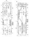
Innerhalb des im wesentlichen zylindrischen Gehäuses 1 ist der hinsichtlich seiner Umrißform ebenfalls im wesentlichen zylindrische Abgaskatalysator 2 integriert. Seine Anordnung ist dabei so getroffen, daß er als Funktionsteil für die Schalldämpfung wirksam ist. Der Katalysator 2 ist am Wandteil 3 des Gehäuses 1 befestigt. Die Abgase des Motors werden dem Katalysator 2 vom Gaseintrittsrohr 4 in Durchströmrichtung 5 zugeführt. Unter Beibehaltung der Durchströmrichtung 5 treten die Abgase aus dem Katalysator 2 aus. Am Ende des Gehäuses 1 treten die Abgase in einen Rohrkrümmer 6, vorzugsweise in einen perforierten U-Rohrkrümmer ein. Der Rohrkrümmer 6 und die an ihn auf seiner Konvexseite angrenzende, mit Absorptionsmaterial 24 aus Mineralfaser ausgekleidete Kammer bilden das Dämpfungsteil 19. Im Rohrkrümmer 6 wird der Abgasstrom um 180° in die Gegenrichtung 8 umgeleitet. In dieser Gegenrichtung 8 wird er an der Außenhaut des Katalysatorgehäuses bzw. des Katalysators 2 entlang dem Gasaustrittsrohr 9 zugeführt, welches mit paralleler Achse neben dem Gaseintrittsrohr 4 an einem Stirnende des Schalldämpfergehäuses 1 befestigt ist.The essentially cylindrical exhaust gas
Bei der Ausführungsform gemäß Fig. 2 strömt das Abgas durch das Gaseintrittsrohr 4 ebenfalls zunächst parallel zur Gehäuseachse 10. Es wird dabei zunächst am Mantel des Katalysatorgehäuses bzw. Katalysators 2 bis zu dem verschlossenen anderen Gehäuseende geführt. Das Entlangführen des heißen Abgasstromes in Durchführungsrichtung 5 am Katalysatorgehäuse bzw. am Katalysator 2 entlang begünstigt dessen schnelles Aufheizen. Am anderen Ende des Schalldämpfergehäuses 1 erfährt der noch ungereinigte Abgasstrom eine Umlenkung um 180° im Bereich 11 der Schalldämpferkammer, die analog Fig. 1 stirnseitig mit einem als Schallabsorber ausgebildeten Dämpfungsteil 19 versehen ist. Der umgelenkte Abgasstrom wird durch den Eingangsstutzen 12 in das Katalysatorgehäuse hinein und in Gegenrichtung 8 parallel zur Gehäuseachse 10 durch den Katalysator 2 hindurchgeführt. Das katalytisch gereinigte Abgas strömt dann weiter dem Ausgangsrohr 9 des Systems zu. Das katalytisch gereinigte Abgas verläßt den Katalysatorraum hierfür über einen Ausgangstrichter und wird über das Ausgangsrohr 9 aus dem Schalldämpfer abtransportiert. Das Ausgangsrohr 9 ist innerhalb des Schalldämpfers im Bereich der Dämpfungskammer 25 perforiert. Die Dämpfungskammer 25 ist mit Schallabsorptionsmaterial 24, und zwar innen mit Stahlwolle 30 und außen mit Absorptionsstoff 31 aus Mineralfaser ausgefüllt. Die Relativlage von Eingangsrohr 4 und Ausgangsrohr 9 entspricht bei der Ausführungsform gemäß Fig. 2 der gemäß Fig. 1.In the embodiment according to FIG. 2, the exhaust gas also initially flows through the
Bei der Ausführungsform gemäß Fig. 3 ist der Katalysator 2 unmittelbar angrenzend an den Umlenkbereich 11 angeordnet. Der Abgasstrom tritt unmittelbar aus dem Umlenkbereich 11 in den Katalysatorkörper 2 ein. Der analog Fig. 2 ausgestaltete und wirksame Dämpfungsteil 19 enthält hier ebenfalls Absorptionsmaterial auf der Innenseite aus Stahlwolle und außen aus Mineralfaser. Er bildet einen gasdurchlässigen, sich über den gesamten Querschnitt des Gehäuses 1 erstreckenden Schallabsorber 32.In the embodiment according to FIG. 3, the
Bei den Ausführungsformen gemäß Fig. 1 - 3 ist der Abgasstrom in Durchströmrichtung vor oder hinter dem Katalysator 2 durch trichterartig aufgeweitete oder eingeschnürte Rohrbereiche geführt, die den Durchmesserunterschied zwischen Katalysator 2 und Gaseintritts- bzw. - austrittsrohr 4,9; 17,18 ausgleichen. In diesen Bereichen wirkt der in Form eines Kegelmantels gestaltete Gasführungsquerschnitt als kontinuierlich breitbandig wirkende Reflexionsstelle.In the embodiments according to FIGS. 1-3, the exhaust gas flow is guided in the flow direction upstream or downstream of the
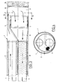
Bei der Ausführungsform gemäß Fig. 5 ist der Abgaskatalysator 13 zwischen den beiden Schalldämpferkammern 14 im Schalldämpfergehäuse 15 angeordnet. Der Katalysator 13 bildet dabei eine die beiden Kammern 14 verbindende Rohrstrecke. Bei dieser Ausführungsform teilt der monolithische Katalysator 13 das Schalldämpfergehäuse 15 in die beiden Kammern 14 auf. Der monolithische Katalysator 13 ist dabei als die Schalldämpferkammer unterteilende Schottwand schalldämmend wirksam. Der Katalysator 13 ist bei dieser Bauform mittels Quellmatte oder Drahtgestrick 16 im Gehäuse 15 gelagert. Das Eingangsrohr 17 ist stirnseitig durch einen Boden 26 verschlossen und in der perforierten Schottwand 27 gelagert. Das Eingangsrohr 17 ist für den Gaseintritt in die Dämpfungskammer mit einem Lochfeld 28 versehen. Der Abgasstrom tritt über die perforierte Schottwand 27 in die Kammer 14 vor dem Katalysator 13, durchströmt ihn und mündet schließlich in die Kammer 14 hinter dem Katalysator. Der Endbereich des Schalldämpfers ist ein Wandresonator und ist mit mineralfaserartigem Absorptionsmaterial 24 ausgefüllt. Bei dieser Ausführungsform verläuft die Durchströmrichtung 5 zwischen Eingangsrohr 17 und Ausgangsrohr 18 parallel zur Gehäuseachse 10.In the embodiment according to FIG. 5, the exhaust gas
Fig. 6 ist eine modifizierte Ausführungsform eines Schalldämpfers mit integriertem Abgaskatalysator 13, dessen Außendurchmesser allerdings im Verhältnis zur Ausführungsform gemäß Fig. 5 deutlich kleiner ist als der Durchmesser des Gehäuses 15.6 is a modified embodiment of a muffler with an integrated exhaust gas
Fig. 7 zeigt eine Monolithanordnung, bei der kein Abgasstrom im Resonatorraum 22 zwischen dem Abgaskatalysator 13 und dem Gehäuse 15 auftritt. Der Resonatorraum 22 ist durch Öffnungen 23 in der Schottwand 20 an das System gekoppelt und als Helmholtz-Resonator wirksam.FIG. 7 shows a monolith arrangement in which no exhaust gas flow occurs in the
- 1.1.
- Gehäusecasing
- 2.2nd
- Katalysatorcatalyst
- 3.3rd
- WandteilWall part
- 4.4th
- GaseintrittsrohrGas inlet pipe
- 5.5.
- DurchströmrichtungFlow direction
- 6.6.
- RohrkrümmerPipe elbow
- 7.7.
- QuellmatteSwelling mat
- 8.8th.
- GegenrichtungOpposite direction
- 9.9.
- GasaustrittsrohrGas outlet pipe
- 10.10th
- GehäuseachseHousing axis
- 11.11.
- BereichArea
- 12.12.
- EingangsstützeEntrance support
- 13.13.
- AbgaskatalysatorCatalytic converter
- 14.14.
- Kammerchamber
- 15.15.
- Gehäusecasing
- 16.16.
- QuellmatteSwelling mat
- 17.17th
- GaseintrittsrohrGas inlet pipe
- 18.18th
- GasaustrittsrohrGas outlet pipe
- 19.19th
- DämpfungsteilDamping part
- 20.20th
- SchottwandBulkhead
- 21.21st
- SchottwandBulkhead
- 22.22.
- ResonatorraumResonator room
- 23.23.
- Öffnungenopenings
- 24.24th
- AbsorptionsmaterialAbsorbent material
- 25.25th
- DämpfungskammerDamping chamber
- 26.26.
- Bodenground
- 27.27th
- SchottwandBulkhead
- 28.28
- LochfeldPerforated field
- 29.29.
- SchottwandBulkhead
- 30.30th
- StahlwolleSteel wool
- 31.31
- MineralfaserMineral fiber
- 32.32.
- SchallabsorberSound absorber
Claims (15)
dadurch gekennzeichnet,
daß innerhalb des Schalldämpfergehäuses (1,15) ein Abgaskatalysator (2,13) als Funktionsteil für die Schalldämpfung wirksam ist.Exhaust silencer for diesel engines, especially of commercial vehicles,
characterized,
that within the muffler housing (1,15), an exhaust gas catalytic converter (2,13) is effective as a functional part for sound absorption.
dadurch gekennzeichnet,
daß der Katalysator (2,13) im Bereich von 2/5 bis 4/5 der Längserstreckung des Schalldämpfergehäuses (1) oder der im Schalldämpfergehäuse (1) durchmessenen Abgaswegstrecke angeordnet ist.Silencer according to claim 1,
characterized,
that the catalytic converter (2, 13) is arranged in the range from 2/5 to 4/5 of the longitudinal extent of the muffler housing (1) or the exhaust gas path section diameter in the muffler housing (1).
dadurch gekennzeichnet,
daß der für den Katalysator (2) eingesetzte Katalysatorträger von monolithischer Form ist.Silencer according to claim 1,
characterized,
that the catalyst support used for the catalyst (2) is of monolithic form.
dadurch gekennzeichnet,
daß der Katalysatorträger aus Metall oder Keramik in Wabenform hergestellt ist.Silencer according to at least one of the preceding claims,
characterized,
that the catalyst carrier is made of metal or ceramic in honeycomb form.
dadurch gekennzeichnet,
daß der Katalysator (2,13) ausgehend vom Gaseintrittsrohr (4,17) an dieses gekoppelt das in Richtung der Abgaswegstrecke erste Dämpfungsglied des Gesamtfunktionsaufbaus ist.Silencer according to one or more of the preceding claims,
characterized,
that the catalytic converter (2,13) is coupled to the gas inlet pipe (4,17) and is the first damping element of the overall functional structure in the direction of the exhaust gas path.
dadurch gekennzeichnet,
daß der Katalysator (2,13) ein in Richtung der Abgaswegstrecke nachgeschaltetes, an das Gasaustrittsrohr (9,18) angekoppeltes Dämpfungsglied des Gesamtfunktionsaufbaues ist.Silencer according to one of claims 1 to 4,
characterized,
that the catalyst (2,13) in the direction of the exhaust gas route downstream attenuator of the overall functional structure which is coupled to the gas outlet pipe (9, 18).
dadurch gekennzeichnet,
daß der Abgasstrom im Gasaustrittsrohr (9) innerhalb des Schalldämpfergehäuses (1) um etwa 180° in Richtung entgegengesetzt zu der des Gaseintrittsrohres (4) umgelenkt ist und daß die ein katalysatorfreies Gasrohr (9 bzw. 4) durchströmenden Abgase zum Aufheizen des Katalysatorträgers bzw. des Katalysators (2) an diesem entlanggeführt sind.Silencer according to claim 5 or 6,
characterized,
that the exhaust gas flow in the gas outlet pipe (9) inside the muffler housing (1) is deflected by approximately 180 ° in the opposite direction to that of the gas inlet pipe (4) and that the exhaust gases flowing through a catalyst-free gas pipe (9 or 4) for heating the catalyst carrier or of the catalyst (2) are guided along this.
dadurch gekennzeichnet,
characterized,
dadurch gekennzeichnet,
daß der Katalysatormantel an der dem Gasaustrittsrohr (9) oder dem Gaseintrittsrohr (4) abgewandten Seite an der Gehäuseinnenseite befestigt ist.Silencer according to claim 8,
characterized,
that the catalyst jacket is attached to the inside of the housing on the side facing away from the gas outlet pipe (9) or the gas inlet pipe (4).
dadurch gekennzeichnet,
daß der Katalysator (13) das Schalldämpfergehäuse (1,15) in mindestens zwei Schalldämpferkammern (14) unterteilt und im Funktionsaufbau des Schalldämpfers die das Gehäuse (1,15) unterteilende Schottwand sowie eine beide Schalldämpferkammern (14) verbindende Rohrstrecke bildet.Silencer according to one or more of the preceding claims,
characterized,
that the catalytic converter (13) divides the muffler housing (1,15) into at least two muffler chambers (14) and, in the functional structure of the muffler, forms the bulkhead dividing the housing (1,15) and a pipe section connecting both muffler chambers (14).
gekennzeichnet durch
einen Funktionsaufbau mit integriertem Katalysator (2) in Reflexionsbauweise.Silencer according to one or more of the preceding claims,
marked by
a functional structure with an integrated catalytic converter (2) in a reflective design.
gekennzeichnet durch
eine Funktionsauslegung mit integriertem Katalysator (2) in gemischter Reflexions-/Absorptionsbauweise.Silencer according to one of claims 1 to 10,
marked by
a functional design with integrated catalyst (2) in a mixed reflection / absorption design.
gekennzeichnet durch
einen Funktionsaufbau mit integriertem Katalysator (2) in Absorptionsbauweise.Silencer according to one of claims 1 to 10,
marked by
a functional structure with an integrated catalyst (2) in absorption design.
dadurch gekennzeichnet,
characterized,
dadurch gekennzeichnet,
daß der integrierte Katalysator (2,13) in Monolithform mittels Quellmatte oder Drahtgestrick (7,16) im Schalldämpfergehäuse (1,15) gelagert ist.Silencer according to one or more of the preceding claims,
characterized,
that the integrated catalyst (2.13) is mounted in monolithic form by means of swelling mat or wire mesh (7.16) in the muffler housing (1.15).
Priority Applications (1)
| Application Number | Priority Date | Filing Date | Title |
|---|---|---|---|
| DE9314441U DE9314441U1 (en) | 1992-02-19 | 1993-02-19 | Exhaust silencer for diesel engines, especially of commercial vehicles |
Applications Claiming Priority (4)
| Application Number | Priority Date | Filing Date | Title |
|---|---|---|---|
| DE9202140U | 1992-02-19 | ||
| DE9202140 | 1992-02-19 | ||
| DE9205461 | 1992-04-22 | ||
| DE9205461U | 1992-04-22 |
Publications (1)
| Publication Number | Publication Date |
|---|---|
| EP0556846A1 true EP0556846A1 (en) | 1993-08-25 |
Family
ID=25959167
Family Applications (1)
| Application Number | Title | Priority Date | Filing Date |
|---|---|---|---|
| EP93102662A Withdrawn EP0556846A1 (en) | 1992-02-19 | 1993-02-19 | Exhaust silencer for diesel engines, particularly for commercial vehicles |
Country Status (1)
| Country | Link |
|---|---|
| EP (1) | EP0556846A1 (en) |
Cited By (16)
| Publication number | Priority date | Publication date | Assignee | Title |
|---|---|---|---|---|
| WO1996016258A1 (en) * | 1994-11-18 | 1996-05-30 | Wci Outdoor Products, Inc. | Catalyst muffler system |
| EP0744536A2 (en) * | 1995-05-19 | 1996-11-27 | Silentor A/S | Silencer |
| WO1997035100A1 (en) * | 1996-03-21 | 1997-09-25 | J. Eberspächer Gmbh & Co | Exhaust silencer arrangement |
| US6312650B1 (en) | 1996-05-15 | 2001-11-06 | Silentor Holding A/S | Silencer |
| US6332510B1 (en) | 1996-09-30 | 2001-12-25 | Silentor Holding A/S | Gas flow silencer |
| EP1170471A2 (en) * | 2000-07-03 | 2002-01-09 | Toyota Jidosha Kabushiki Kaisha | Exhaust device of internal combustion engine |
| FR2820341A1 (en) * | 2001-02-06 | 2002-08-09 | Bosch Gmbh Robert | DEVICE FOR TREATMENT OF EXHAUST GASES FROM AN INTERNAL COMBUSTION ENGINE INCLUDING AN ACCUMULATOR CATALYST |
| CN1100199C (en) * | 1997-01-22 | 2003-01-29 | 本田技研工业株式会社 | Exhauster with catalytic agent |
| US6520286B1 (en) | 1996-09-30 | 2003-02-18 | Silentor Holding A/S | Silencer and a method of operating a vehicle |
| EP2017441A1 (en) | 2007-06-04 | 2009-01-21 | MAN Nutzfahrzeuge Österreich AG | Exhaust gas system comprising two parallel arranged dampers |
| CN101482045A (en) * | 2009-02-03 | 2009-07-15 | 重庆隆鑫机车有限公司 | Silencer of all-terrain vehicle |
| EP2458172A1 (en) * | 2010-11-24 | 2012-05-30 | CNH Italia S.p.A. | Mixing pipe for SCR mufflers. |
| WO2019166444A1 (en) * | 2018-03-01 | 2019-09-06 | Cpt Group Gmbh | Exhaust gas aftertreatment device |
| CN112303030A (en) * | 2019-07-29 | 2021-02-02 | 无锡小天鹅电器有限公司 | Silencer and clothes treatment equipment |
| US11181027B2 (en) | 2018-04-02 | 2021-11-23 | Cummins Emission Solutions Inc. | Aftertreatment system including noise reducing components |
| US11486289B2 (en) | 2018-07-03 | 2022-11-01 | Cummins Emission Solutions Inc. | Body mixing decomposition reactor |
Citations (5)
| Publication number | Priority date | Publication date | Assignee | Title |
|---|---|---|---|---|
| US4209493A (en) * | 1977-07-11 | 1980-06-24 | Nelson Industries, Inc. | Combination catalytic converter and muffler for an exhaust system |
| CA1262869A (en) * | 1988-06-23 | 1989-11-14 | Glen Knight | Combined muffler and catalytic converter exhaust unit |
| EP0392575A2 (en) * | 1989-04-12 | 1990-10-17 | I.R.T.I. Istituto Di Ricerca E Trasferimenti Tecnologici Alle Imprese S.R.L. | Exhaust gas cleaner with catalytic activity, and silencer for internal combustion engines |
| EP0393257A1 (en) * | 1989-04-17 | 1990-10-24 | Emitec Gesellschaft für Emissionstechnologie mbH | Diesel soot filter with an additional arrangement for the reduction of nitrogen oxides and/or the oxidation of carbon monoxide |
| EP0457287A2 (en) * | 1990-05-18 | 1991-11-21 | Guiseppe Nieri | An anti-pollution device for treating the exhaust gases from internal combustion engines and burners in general, functioning also as exhaust silencer |
-
1993
- 1993-02-19 EP EP93102662A patent/EP0556846A1/en not_active Withdrawn
Patent Citations (5)
| Publication number | Priority date | Publication date | Assignee | Title |
|---|---|---|---|---|
| US4209493A (en) * | 1977-07-11 | 1980-06-24 | Nelson Industries, Inc. | Combination catalytic converter and muffler for an exhaust system |
| CA1262869A (en) * | 1988-06-23 | 1989-11-14 | Glen Knight | Combined muffler and catalytic converter exhaust unit |
| EP0392575A2 (en) * | 1989-04-12 | 1990-10-17 | I.R.T.I. Istituto Di Ricerca E Trasferimenti Tecnologici Alle Imprese S.R.L. | Exhaust gas cleaner with catalytic activity, and silencer for internal combustion engines |
| EP0393257A1 (en) * | 1989-04-17 | 1990-10-24 | Emitec Gesellschaft für Emissionstechnologie mbH | Diesel soot filter with an additional arrangement for the reduction of nitrogen oxides and/or the oxidation of carbon monoxide |
| EP0457287A2 (en) * | 1990-05-18 | 1991-11-21 | Guiseppe Nieri | An anti-pollution device for treating the exhaust gases from internal combustion engines and burners in general, functioning also as exhaust silencer |
Cited By (24)
| Publication number | Priority date | Publication date | Assignee | Title |
|---|---|---|---|---|
| WO1996016258A1 (en) * | 1994-11-18 | 1996-05-30 | Wci Outdoor Products, Inc. | Catalyst muffler system |
| EP0744536A2 (en) * | 1995-05-19 | 1996-11-27 | Silentor A/S | Silencer |
| EP0744536A3 (en) * | 1995-05-19 | 1997-11-05 | Silentor A/S | Silencer |
| US6220021B1 (en) | 1995-05-19 | 2001-04-24 | Silentor Notox A/S | Silencer with incorporated catalyst |
| WO1997035100A1 (en) * | 1996-03-21 | 1997-09-25 | J. Eberspächer Gmbh & Co | Exhaust silencer arrangement |
| US6158214A (en) * | 1996-03-21 | 2000-12-12 | Microcompact Car Smart Gmbh | Exhaust silencer arrangement |
| US6312650B1 (en) | 1996-05-15 | 2001-11-06 | Silentor Holding A/S | Silencer |
| US6520286B1 (en) | 1996-09-30 | 2003-02-18 | Silentor Holding A/S | Silencer and a method of operating a vehicle |
| US6332510B1 (en) | 1996-09-30 | 2001-12-25 | Silentor Holding A/S | Gas flow silencer |
| CN1100199C (en) * | 1997-01-22 | 2003-01-29 | 本田技研工业株式会社 | Exhauster with catalytic agent |
| EP1170471A2 (en) * | 2000-07-03 | 2002-01-09 | Toyota Jidosha Kabushiki Kaisha | Exhaust device of internal combustion engine |
| EP1170471A3 (en) * | 2000-07-03 | 2002-11-27 | Toyota Jidosha Kabushiki Kaisha | Exhaust device of internal combustion engine |
| US6588203B2 (en) | 2000-07-03 | 2003-07-08 | Toyota Jidosha Kabushiki Kaisha | Exhaust device of internal combustion engine |
| FR2820341A1 (en) * | 2001-02-06 | 2002-08-09 | Bosch Gmbh Robert | DEVICE FOR TREATMENT OF EXHAUST GASES FROM AN INTERNAL COMBUSTION ENGINE INCLUDING AN ACCUMULATOR CATALYST |
| EP2017441A1 (en) | 2007-06-04 | 2009-01-21 | MAN Nutzfahrzeuge Österreich AG | Exhaust gas system comprising two parallel arranged dampers |
| CN101482045A (en) * | 2009-02-03 | 2009-07-15 | 重庆隆鑫机车有限公司 | Silencer of all-terrain vehicle |
| EP2458172A1 (en) * | 2010-11-24 | 2012-05-30 | CNH Italia S.p.A. | Mixing pipe for SCR mufflers. |
| WO2019166444A1 (en) * | 2018-03-01 | 2019-09-06 | Cpt Group Gmbh | Exhaust gas aftertreatment device |
| CN111788373A (en) * | 2018-03-01 | 2020-10-16 | 纬湃技术有限公司 | Device for exhaust gas aftertreatment |
| US11174775B2 (en) | 2018-03-01 | 2021-11-16 | Vitesco Technologies GmbH | Exhaust gas aftertreatment device |
| US11181027B2 (en) | 2018-04-02 | 2021-11-23 | Cummins Emission Solutions Inc. | Aftertreatment system including noise reducing components |
| US11486289B2 (en) | 2018-07-03 | 2022-11-01 | Cummins Emission Solutions Inc. | Body mixing decomposition reactor |
| US11891937B2 (en) | 2018-07-03 | 2024-02-06 | Cummins Emission Solutions Inc. | Body mixing decomposition reactor |
| CN112303030A (en) * | 2019-07-29 | 2021-02-02 | 无锡小天鹅电器有限公司 | Silencer and clothes treatment equipment |
Similar Documents
| Publication | Publication Date | Title |
|---|---|---|
| EP0556846A1 (en) | Exhaust silencer for diesel engines, particularly for commercial vehicles | |
| EP1108122B1 (en) | Device for catalytic exhaust gas purification | |
| EP1184543B1 (en) | Exhaust purification system for motor vehicles, particularly Diesel utility vehicles | |
| DE19955013B4 (en) | Exhaust system of an internal combustion engine | |
| DE112011103501T5 (en) | Exhaust system for motor vehicles | |
| EP1379322B2 (en) | Exhaust gas system | |
| DE102007062662A1 (en) | Sliding seat and exhaust treatment device | |
| EP1179125B1 (en) | Method for reducing harmful components in the exhaust gas of an internal combustion engine, especially a diesel-internal combustion engine | |
| DE202007010435U1 (en) | Exhaust system for commercial vehicles | |
| DE2539964A1 (en) | DEVICE FOR CLEANING EXHAUST GASES | |
| EP1475522B1 (en) | Combined exhaust gas treating/sound attenuation device in the exhaust line of an internal combustion engine | |
| DE102004042454A1 (en) | Exhaust gas heat exchanger for exhaust gas recirculation in motor vehicles is connected to oxidation catalyst arranged upstream of heat exchanger | |
| AT396170B (en) | EXHAUST SYSTEM FOR TWO-STROKE COMBUSTION ENGINES | |
| EP3704360B1 (en) | Exhaust gas system for compact and efficient aftertreatment and sound damping of the exhaust gas | |
| EP4086439A1 (en) | Exhaust gas treatment module | |
| DE202009012225U1 (en) | Sound attenuation in the exhaust path of a rail vehicle internal combustion engine | |
| EP1882090B1 (en) | Exhaust system with two exhaust treatment units | |
| EP1304152B1 (en) | Exhaust system with particle filter for an internal combustion engine | |
| DE19626980A1 (en) | Silencers for automobiles | |
| DE19952428A1 (en) | Method and device for the combined catalytic NOx reduction and sound attenuation of exhaust gas in the exhaust line of an internal combustion engine | |
| EP0884460A2 (en) | Exhaust system, suitable for retrofitting exhaust catalysts in motorcycles | |
| DE102011051464A1 (en) | Exhaust gas filtering apparatus for use in combustion engine i.e. diesel engine, has flow comparison moderation unit arranged within filter unit to displace exhaust gas such that exhaust gas flows uniformly in direction of filter unit | |
| DE60214748T2 (en) | HOUSING ARRANGED IN AN EXHAUST SYSTEM FOR A COMBUSTION ENGINE | |
| DE10329436B4 (en) | Emission control system for an internal combustion engine | |
| EP0273232A2 (en) | Method for purifying exhaust gases of internal-combustion engines, and catalytic converter |
Legal Events
| Date | Code | Title | Description |
|---|---|---|---|
| PUAI | Public reference made under article 153(3) epc to a published international application that has entered the european phase |
Free format text: ORIGINAL CODE: 0009012 |
|
| AK | Designated contracting states |
Kind code of ref document: A1 Designated state(s): BE DE ES FR GB IT NL SE |
|
| STAA | Information on the status of an ep patent application or granted ep patent |
Free format text: STATUS: THE APPLICATION IS DEEMED TO BE WITHDRAWN |
|
| 18D | Application deemed to be withdrawn |
Effective date: 19940226 |