EP0557190A1 - Assembly of stacked articulated modules - Google Patents
Assembly of stacked articulated modules Download PDFInfo
- Publication number
- EP0557190A1 EP0557190A1 EP93400397A EP93400397A EP0557190A1 EP 0557190 A1 EP0557190 A1 EP 0557190A1 EP 93400397 A EP93400397 A EP 93400397A EP 93400397 A EP93400397 A EP 93400397A EP 0557190 A1 EP0557190 A1 EP 0557190A1
- Authority
- EP
- European Patent Office
- Prior art keywords
- strip
- modules
- assembly according
- assembly
- elements
- Prior art date
- Legal status (The legal status is an assumption and is not a legal conclusion. Google has not performed a legal analysis and makes no representation as to the accuracy of the status listed.)
- Granted
Links
- 239000000835 fiber Substances 0.000 claims description 25
- 210000005069 ears Anatomy 0.000 claims description 6
- 239000013307 optical fiber Substances 0.000 claims description 6
- 230000000295 complement effect Effects 0.000 claims description 5
- 230000000903 blocking effect Effects 0.000 claims description 3
- 230000002093 peripheral effect Effects 0.000 claims description 2
- 230000003287 optical effect Effects 0.000 description 6
- 240000008042 Zea mays Species 0.000 description 4
- 238000012550 audit Methods 0.000 description 4
- 238000012423 maintenance Methods 0.000 description 3
- 230000000717 retained effect Effects 0.000 description 3
- 230000006978 adaptation Effects 0.000 description 2
- 230000014759 maintenance of location Effects 0.000 description 2
- 241000212322 Levisticum officinale Species 0.000 description 1
- 229910000746 Structural steel Inorganic materials 0.000 description 1
- 238000005253 cladding Methods 0.000 description 1
- 230000008878 coupling Effects 0.000 description 1
- 238000010168 coupling process Methods 0.000 description 1
- 238000005859 coupling reaction Methods 0.000 description 1
- 230000000694 effects Effects 0.000 description 1
- 238000007373 indentation Methods 0.000 description 1
- 239000001645 levisticum officinale Substances 0.000 description 1
- 238000000465 moulding Methods 0.000 description 1
- 238000000926 separation method Methods 0.000 description 1
Images


Classifications
-
- G—PHYSICS
- G02—OPTICS
- G02B—OPTICAL ELEMENTS, SYSTEMS OR APPARATUS
- G02B6/00—Light guides; Structural details of arrangements comprising light guides and other optical elements, e.g. couplings
- G02B6/44—Mechanical structures for providing tensile strength and external protection for fibres, e.g. optical transmission cables
- G02B6/4439—Auxiliary devices
- G02B6/444—Systems or boxes with surplus lengths
- G02B6/4452—Distribution frames
- G02B6/44524—Distribution frames with frame parts or auxiliary devices mounted on the frame and collectively not covering a whole width of the frame or rack
-
- G—PHYSICS
- G02—OPTICS
- G02B—OPTICAL ELEMENTS, SYSTEMS OR APPARATUS
- G02B6/00—Light guides; Structural details of arrangements comprising light guides and other optical elements, e.g. couplings
- G02B6/44—Mechanical structures for providing tensile strength and external protection for fibres, e.g. optical transmission cables
- G02B6/4439—Auxiliary devices
- G02B6/444—Systems or boxes with surplus lengths
- G02B6/4453—Cassettes
- G02B6/4454—Cassettes with splices
-
- G—PHYSICS
- G02—OPTICS
- G02B—OPTICAL ELEMENTS, SYSTEMS OR APPARATUS
- G02B6/00—Light guides; Structural details of arrangements comprising light guides and other optical elements, e.g. couplings
- G02B6/44—Mechanical structures for providing tensile strength and external protection for fibres, e.g. optical transmission cables
- G02B6/4439—Auxiliary devices
- G02B6/444—Systems or boxes with surplus lengths
- G02B6/4453—Cassettes
- G02B6/4455—Cassettes characterised by the way of extraction or insertion of the cassette in the distribution frame, e.g. pivoting, sliding, rotating or gliding
Definitions
- the present invention relates to the assembly of superimposable modules into a set, these modules being made accessible in said set by opening the modules around a hinge axis provided for each of them. It relates to such a set of stacked and articulated modules, in which said modules are more particularly coiling cassettes and optionally for connecting optical fibers.
- cassettes are boxes for coiling and protecting optical fibers and often also for protecting fittings of coiled optical fibers. They are used for connecting different optical cables or an optical cable to optical jumpers.
- Each cassette is assigned to two fibers to be connected one or the other or preferably to several fibers to be individually connected to several other fibers.
- cassettes are generally assigned to the processing of all the fibers of one or more optical cables to be connected to one or other optical cables or jumpers in a connection box. They are stacked in a set for their maintenance with a smaller footprint in the housing and are mounted articulated to have access to each of them, in particular for maintenance operations.
- Document FR-A-2 646 928 describes such a set of cassettes in a connection box for fiber optic cables.
- the set of cassettes is mounted at the end of a support plate on which the ends of the cables to be connected are fixed. This support plate is flanked by lateral cheeks to define a protected space for the transfer of fibers, left in excess length on the ends of the cables, to all of the cassettes.
- each of them carries a pair of lateral arms which are pivotable around a pair of articulation axes on the lateral cheeks of the support plate.
- Each has a limited stroke possible in rotation relative to the plane of the support plate, for placing it in the open position transversely to the support plate.
- Temporary latching means are provided at the coupling of each pair of arms on its pair of articulation axes to limit this rotational travel and define an open position.
- the present invention aims to avoid such drawbacks by allowing the assembly of modules and the simultaneous articulation of each of them, substantially by one of the edges of each module.
- a set of stacked and articulated modules in which said modules are flat and substantially rectangular and have two large superimposable faces and peripheral edges two to two opposite, comprising a support and means for holding and articulation of the modules.
- said first module kept fixed by defining a so-called closed position of each of the other modules relative to said first module, characterized in that said support is an assembly strip and articulation, comprising of part of the first means for mounting and retaining said individual modules, substantially against a so-called front face of said strip, and on the other hand individual hinges, being both in step with said modules stacked in said assembly, and in that each of said modules is equipped on a first of said edges with second mounting and retaining means complementary to said first, by blocking the module on said strip.
- the set of stacked and articulated modules according to the invention is in particular constituted by cassettes of optical fibers.
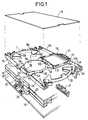
- Figure 1 shows a terminal cassette 10 of the assembly, which is illustrated in exploded perspective and two other cassettes 10 'and 10''similar to the previous one and already stacked one on the other and each articulated.
- These modules can be housings other than optical cassettes, which are assembled into a set of stacked and individually articulated housings, in accordance with the present invention.
- the cassette 10 is described with reference to FIG. 1 or 2. It has a flat bottom 1, substantially rectangular, the short sides of which are partially truncated and arched. Two opposite and straight edges 2A and two other opposite and arched edges 2B surround the bottom. Their terminals define between them on the bottom, four so-called double accesses, at the four corners of the bottom, for the fibers received in the cassette.
- Plots 4 projecting from the bottom 1 and each centered in each double access, divide each of said double accesses into two access channels 3A and 3B.
- These studs are the same height as the edges and of substantially triangular section.
- Two lateral faces 4A and 4B of each stud are opposite the end portions of the edges of each double access and delimit laterally with these end portions each access channel.
- a protuberance 4C on each stud extends its lateral face 4B opposite the terminal part of the rim 2B, towards the outside of the cassette.
- Tabs 5A, on the edges 2A, and 5B on the edges 2B extend parallel to the bottom 1 on the inside of the cassette.
- Two other legs 5C similar to the legs 5A protrude from the bottom, substantially on one side of its median longitudinal axis. These tabs 5A, 5B and 5C serve to hold the fibers coiled in the cassette under them.
- the bottom 1 is made of plastic and is molded. The edges, the studs and the legs come from molding with the bottom.
- the bottom 1 is equipped with a support 6, receiving and holding on it fittings such as 16 of optical fibers, and a cylinder 7 for coiling the fibers. Both are removably mounted side by side across the width of the bottom, in its middle part.
- the support and the cylinder have for this purpose a set of latching tabs, formed by two rigid tabs 6A and a third elastic band 6B on the support and a rigid tab 7A and one or two other elastic tabs 7B on the cylinder.
- the bottom 1 has meanwhile sets of openings not referenced, corresponding in particular to the set of lugs of each of these elements, for their snap-fastening.
- the support for fittings is chosen from different possible supports for different types of fittings, comprising support 6 above and other supports such as 6 'and 6' '( Figure 2).
- the aforementioned cylinder 7 may not itself be used, in this case two supports 6, 6 ', 6' 'can be mounted on the bottom.
- Different sets of openings are initially provided on the bottom for the selective mounting of these elements 6, 6 ', 6' 'and 7 on the bottom and adaptation to the demand of the resulting cassette.
- the tabs 5A and 5C can be removed if necessary, for the desired adaptation of the cassette.
- two of the four double accesses 3 are selected, as well as one of the two access channels 3A and 3B of each selected double access, according to the mode of use of the cassette while guaranteeing a minimum radius of curvature of the fibers entering the cassette.
- the two selected access channels are themselves optionally equipped with an element of a first type 8 and / or of a second type 9, of unitary separation in line and of keeping the fibers that each of them receives.
- the element of the first type 8 is assigned to bare fibers 12 and consists of a flexible block which can be mounted and blocked in any of the access channels. It has a series of slots 8A which extend side by side over the width of the access channel in which it is mounted and blocked.
- the element of the second type 9 is assigned to fibers 13 initially protected in individual tubes of cladding 14. It is made up of a U-shaped piece whose facing branches are formed by a series of teeth. The teeth define slots therebetween, facing one branch to another and side by side over the width of any of the access channels in which this element is mounted and blocked. A tab 11, independent of the element 9 and the bottom 1, is associated with this element. It is fixed by one of its ends to the stud 4 and extends over the element 9 to guarantee the retention of tubed fibers in its slots. As a variant, the cased fibers can be retained in the access channel receiving them by a collar, not shown.
- the cassette 10 further comprises, for its assembly and locking on the cassette 10 ', a pair of guide tabs 17, 18 on its edges 2A. These pairs of guide tabs project from the outside and the height of the flanges 2A.
- the legs of each of them are in the form of an angle iron and facing each other while being symmetrical with respect to the median transverse axis of the cassette.
- the cassettes 10, 10 'and 10' ' are all identical at least externally. They can be superimposed in a stack produced on a base planar support 19 and constitute on this base support the set of stacked and articulated cassettes according to the present invention.
- This set of cassettes comprises a strip 20 for assembly and articulation of the individual cassettes 10, 10 'and 10''and a set of individual devices 21 for locking the cassettes.
- This strip 20 and these devices 21 are received and retained in one and the other, respectively, of the two pairs of guide tabs 17, 18 of the different cassettes.
- the assembly and articulation strip 20 defines axes or articulation hinges 22 for the individual cassettes, except for the first cassette 10 '' of the stack. These articulation axes 22 are in step with cassettes over the height of the stack.
- the rule 20 has two fixing lugs 23, at its end located at the bottom of the stack. These fixing lugs 23 are secured by screws or the like to the base support 19 and make the first cassette fixed on the latter, in a so-called closed position.
- a pair of retaining fingers 24 or 25 protrudes from the outer face of each flange 2A. It is internal to the pair of guide tabs 17 or 18 and ensures the retention on it of the strip 20 or of the locking device 21 mounted in the pair of guide tabs.
- the four double accesses at the four corners of the cassette and the two access channels of each of them make it possible to select two access channels for the fibers, belonging to two of the accesses doubles themselves selected.
- the articulated assembly of the cassettes along one of their edges 2A and their locking on the other edge are made selectively. The articulated assembly is carried out on that of the edges 2A to which the two selected double accesses 3 do not belong, when the fibers arrive along the edges 2B in their access channels 3A or 3B.
- each cassette of the assembly is at a distance from the two selected double accesses, which is substantially equal to the width of the cassette.
- the assembly and articulation strip 20 is described in detail with reference to FIGS. 3 to 10. It has an axis of symmetry XX over the height of the stack of cassettes of the assembly.
- XX axis of symmetry
- FIG. 3 a first and a second embodiment of this strip 20 have been illustrated to the left and to the right of this axis XX, this second embodiment being simply suggested in dotted lines in FIG. 4.
- first strip 20 is a molded piece in one piece, while in the second it is formed of individual molded elements such as 26, 26A and 27 which are assembled non-contiguously one after the other by two assembly strips such as the only 28 shown.
- the strip in one piece has comparable sections connected to each other but not contiguous, which correspond to the individual elements 26, 26A and 27 and are referenced as these elements.
- Each assembly strip 28 has holes 28A at the pitch of assembly of the individual elements. It is threaded into the slots 29 of the individual elements and fixed to each of them by means of a screw 30 or the like engaged in the corresponding hole 28A and screwed or anchored in the individual element concerned (FIGS. 6, 8, 10).
- the hinges 22 are defined by sections of reduced thickness and low height provided directly on this strip between its successive sections thus connected one after the other.
- the hinges 22 are defined on each strip 28, also by sections of reduced thickness and low height on the strip, coming between two successive individual elements.
- these reduced sections or hinges 22 are in step stacked cassettes of the assembly formed.
- the first section 26A at the bottom of the stack is distinguished from the section or sections 26 by the pair of fixing lugs 23 which it presents for its fixing to the base support 19. These lugs extend under the pair of front stops, truncated and denoted 34A, and depart from the edges of the recess 35.
- front stops 35 have their so-called upper and lower faces chamfered at 45 °. Their edge is halfway up each section or element. They define the opening position of the individual cassettes at 90 ° from their closed position and prohibit opening beyond this defined position.
- a female element can alternatively constitute the first section fixed to the bottom of the stack on the base support, the following elements then being alternately male and female.
- the mounting and stacking of the cassettes on the assembly and articulation strip 20 is done after constitution, if necessary, of the strip, when the latter is made up of individual elements.
- the fixing lugs 23 can then be fixed on the base support 19 or are last.
- the pair of guide tabs 17 on the corresponding flange 2A of the first cassette is threaded into the lateral tabs 32 of the section or element 26A of the strip. This is done by releasing by folding around the hinge 22 adjoining the section or element 26A all sections or upper elements.
- the other cassettes are mounted successively and identically to the first cassette.
- the set of cassettes being constituted and fixed on the base support, it is noted that the strip 20 ensures itself the holding of the cassettes in the closed position on each other. This natural outfit is not entirely safe, however.
- the locking of the cassettes on each other in the closed position but also in the open position is ensured by the devices 21 individually attached to the other edge 2A of the cassettes. These devices also allow the locking of a group of successive upper cassettes, one on the other in the open position while the lower cassette or cassettes forming the other group are themselves locked in closing. They release the individual cassettes for their passage from one group to another.
- the device 21 is an elongated molded body, of height and length similar to that of a section or element of the assembly and articulation strip described above. Provisions also similar to the previous ones are provided on the device 21, with regard to its mounting on any one of the cassettes against the flange 2A available thereof.
- this assembly has a pair of lateral tabs 42 and a rear recess 43.
- These fingers and centering holes are defined on two portions 49, in excess thickness on the device, which are adjacent to one and the other of the lateral tabs 42 but offset from the central latching latch 44.
- the centering fingers 47 have their front facet and the tips of their other facets chamfered. They are thus made easy to engage in the centering holes of another identical device, which is carried by the adjacent cassette and lower than that carrying the device considered. This centering prevents the hinges from being subjected to a particular force when locking devices 21.
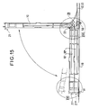
- FIGS. 15 to 17 clearly show the articulated assembly, the locking and the possible opening of the cassettes of the assembly which they form on the basic plane support.
- the strip 20 illustrated is that of a single piece according to the aforementioned first embodiment. Its three sections are designated successively by their references 26A, 27 and 26 for the three illustrated cassettes.
- the cassette 10 'shown in the closed position has its locking device 21' centered and snapped onto the device 21 ''.
- the cassette 10 is shown in the open position.
- the lower faces of the stops 34 are then in abutment against the upper faces of the stops 34 'and the bosses 27 engaged in the openings of the elastic branches 38.
- This opening is provided around the hinge 22 almost adjacent to the lower edge of the rim 2A concerned. It is obtained by unlocking from the device 21, this unlocking being achieved by actuating the lever 46 to release its latching tab from the device 21 '.
- Figures 18 to 23 relate to the constitution of an assembly and articulation strip according to a third embodiment.
- This strip is made up of individual elements, such as the element 60 described in detail with reference to FIGS. 18 to 20, which are all identical and fitted directly on top of each other.
- the element 60 is a molded body on which provisions comparable to those on each section or element of the strip described above or on the locking device described above are provided, as regards its mounting on any of the cassettes and on one of the two edges 2A of this cassette.
- These ears have a shoulder at the upper edge of the element, each dividing them into a lower part 65 secured to the front face and rigid and an upper part 66 made slightly flexible and deformable around its junction with the lower part.
- the upper and lower edges of each ear are rounded. Their front edge is straight.
- the lower parts of these two ears each have a central hole 67.
- the upper parts have a cylindrical finger 68, projecting from each of them.
- the lower parts 65 being more external than the upper parts 66, the cylindrical fingers 68 are protruding on the external faces of the upper parts.
- the lower parts 65 have a boss 70 on their inner face and the upper parts 66 have two indentations 71A and 71B in their outer face.
- the boss 70 is on the edge of the hole 67 and of low height.
- the two imprints are at the foot of the cylindrical finger 68. They are complementary to the boss 70 and are offset by 90 ° from each other, as shown between their axes in FIG. 20.
- One of them, 71A corresponds to the position of the boss when two elements are assembled and define the closed position.
- the element 60 also has a central fixing tab 73, protruding on its front face from its lower edge.
- This tab 73 has two holes 74.
- Figures 21 to 23 show an assembly and articulation strip, generally noted 20A, which consists of elements 60, 60 ', 60'', all identical, and is mounted on cassettes 10, 10' and 10 '' above and their aforementioned basic support 19.
- the constitution of the strip and the obtaining of the articulation axes is explained by distinguishing by the sign "prime” or "second” the Identical functional arrangements provided for on the different 60, 60 'and 60''elements.
- the constitution of the strip 20A is carried out initially or as the cassettes 10 '', 10 'and 10 are stacked on the base support 19, the cassettes then each carrying their element 60' ', 60', 60.
- the element 60 '' is fixed to the base support 19 by two screws 75 blocking its fixing lug 73 '' on the base support.
- the holes 67 '' left empty correspond to the absence of hinge hinge of the cassette 10 ''.
- This element 60 '' on the other hand has its cylindrical fingers 68 '' engaged in the holes 67 'of the element 60', which thus define the hinge 22'A of the cassette 10 '.
- the hinge 22A of the cassette 10 is defined in a similar manner by the cylindrical fingers 68 'engaged in the holes 67 of the element 60.
- each of the cassettes 10 'and 10 are defined by the boss-imprint pairs 70' - 71 '' A and 70 - 71'A.
- Their open position is defined by the boss-imprint pairs 70 '- 71' 'B and 70 - 71' B, as can be seen in FIG. 23 for the cassette 10 shown in this open position. It is noted that in this open position the inner edge of the shoulder or stop 69 is in abutment on the upper part of the ears 64 ′ and is opposed to opening the cassette 10 over more than 90 °. similarly between the stop 69 'and the ear 64' 'when the cassette 10' is open in turn.
- central fixing lugs 73 'and 73 of the elements 60' and 60 '' have no effect in the strip 20A. They may not exist, the element 60 '' then being the only one to have such a tab 73 '', distinguishing it from the previous ones.
- the assembly strip of a single piece or the individual elements which constitute it are molded.
Abstract
Description
La présente invention concerne l'assemblage de modules superposables en un ensemble, ces modules étant rendus accessibles dans ledit ensemble par ouverture des modules autour d'un axe d'articulation prévu pour chacun d'eux. Elle porte sur un tel ensemble de modules empilés et articulés, dans lequel lesdits modules sont plus particulièrement des cassettes de lovage et éventuellement de raccordement de fibres optiques.The present invention relates to the assembly of superimposable modules into a set, these modules being made accessible in said set by opening the modules around a hinge axis provided for each of them. It relates to such a set of stacked and articulated modules, in which said modules are more particularly coiling cassettes and optionally for connecting optical fibers.
Ces cassettes sont des boites de lovage et de protection de fibres optiques et souvent également de protection de raccords des fibres optiques lovées. Elles sont utilisées pour le raccordement de différents câbles optiques ou d'un câble optique à des jarretières optiques. Chaque cassette est affectée à deux fibres à raccorder l'une ou l'autre ou de préférence à plusieurs fibres à raccorder individuellement à plusieurs autres fibres.These cassettes are boxes for coiling and protecting optical fibers and often also for protecting fittings of coiled optical fibers. They are used for connecting different optical cables or an optical cable to optical jumpers. Each cassette is assigned to two fibers to be connected one or the other or preferably to several fibers to be individually connected to several other fibers.
Plusieurs cassettes sont en général affectées au traitement de la totalité des fibres d'un ou de plusieurs câbles optiques à raccorder à un ou d'autres câbles optiques ou des jarretières dans un boîtier de raccordement. Elles sont empilées en un ensemble pour leur maintien avec un moindre encombrement dans le boîtier et sont montées articulées pour avoir accès à chacune d'elles, notamment pour des opérations de maintenance.Several cassettes are generally assigned to the processing of all the fibers of one or more optical cables to be connected to one or other optical cables or jumpers in a connection box. They are stacked in a set for their maintenance with a smaller footprint in the housing and are mounted articulated to have access to each of them, in particular for maintenance operations.
Le document FR-A- 2 646 928 décrit un tel ensemble de cassettes dans un boîtier de raccordement de câbles à fibres optiques. Selon ce document, l'ensemble de cassettes est monté en bout d'un plateau support sur lequel sont fixées les extrémités des câbles à raccorder. Ce plateau support est flanqué de joues latérales pour définir un espace protégé de transfert des fibres, laissées en surlongueur sur les extrémités des câbles, à l'ensemble des cassettes.Document FR-A-2 646 928 describes such a set of cassettes in a connection box for fiber optic cables. According to this document, the set of cassettes is mounted at the end of a support plate on which the ends of the cables to be connected are fixed. This support plate is flanked by lateral cheeks to define a protected space for the transfer of fibers, left in excess length on the ends of the cables, to all of the cassettes.
Dans cet ensemble les cassettes sont empilées en présentant un léger décalage l'une sur l'autre et sont articulées autour d'axes individuels décalés pareillement les uns des autres. A cet effet, chacune d'elles portent une paire de bras latéraux qui sont pivotants autour d'une paire d'axes d'articulation sur les joues latérales du plateau support. Chacune présente une course limitée possible en rotation relativement au plan du plateau support, pour sa mise en position d'ouverture transversalement au plateau support. Des moyens d'encliquetage temporaire sont prévus au niveau du couplage de chaque paire de bras sur sa paire d'axes d'articulation pour limiter cette course en rotation et définir une position d'ouverture.In this set the cassettes are stacked with a slight offset one on the other and are articulated around individual axes offset equally one another. For this purpose, each of them carries a pair of lateral arms which are pivotable around a pair of articulation axes on the lateral cheeks of the support plate. Each has a limited stroke possible in rotation relative to the plane of the support plate, for placing it in the open position transversely to the support plate. Temporary latching means are provided at the coupling of each pair of arms on its pair of articulation axes to limit this rotational travel and define an open position.
Ces dispositions de montage et d'ouverture des cassettes sont relativement complexes, peu aisées à mettre en oeuvre et fragiles. Elles imposent le maintien de l'ensemble et des cassettes qui le compose sur les joues d'un support en U. Elles conduisent à une ouverture des cassettes qui est relativement délicate, du fait de leur montage sur de longs bras articulés. Bien qu'elles soient prévues pour limiter les contraintes et courbures excessives des fibres, le manque de stabilité des cassettes lors de leur ouverture ne permet pas de garantir le maintien des fibres dans les conditions requises.These arrangements for mounting and opening the cassettes are relatively complex, not very easy to implement and fragile. They impose the maintenance of the assembly and of the cassettes which compose it on the cheeks of a U-shaped support. They lead to an opening of the cassettes which is relatively delicate, due to their mounting on long articulated arms. Although they are designed to limit the excessive stresses and curvatures of the fibers, the lack of stability of the cassettes when they are opened does not guarantee that the fibers are kept in the required conditions.
La présente invention a pour but d'éviter de tels inconvénients en permettant l'assemblage de modules et l'articulation simultanée de chacun d'eux, sensiblement par l'un des bords de chaque module.The present invention aims to avoid such drawbacks by allowing the assembly of modules and the simultaneous articulation of each of them, substantially by one of the edges of each module.
Elle a pour objet un ensemble de modules empilés et articulés, dans lequel lesdits modules sont plats et sensiblement rectangulaires et ont deux grandes faces superposables et des bords périphériques deux à deux opposés, comportant un support et des moyens de maintien et d'articulation des modules individuels, à l'exception éventuelle du module terminal de l'ensemble, dit premier module, maintenu fixe en définissant une position dite de fermeture de chacun des autres modules relativement audit premier module, caractérisé en ce que ledit support est une réglette d'assemblage et d'articulation, comportant d'une part des premiers moyens de montage et retenue desdits modules individuels, sensiblement contre une face dite avant de ladite réglette, et d'autre part des charnières individuelles, en étant les uns et les autres au pas desdits modules empilés dudit ensemble, et en ce que chacun desdits modules est équipé sur un premier desdits bords de deuxièmes moyens de montage et retenue complémentaires desdits premiers, en bloquant le module sur ladite réglette.It relates to a set of stacked and articulated modules, in which said modules are flat and substantially rectangular and have two large superimposable faces and peripheral edges two to two opposite, comprising a support and means for holding and articulation of the modules. individual, with the possible exception of the terminal module of the assembly, said first module, kept fixed by defining a so-called closed position of each of the other modules relative to said first module, characterized in that said support is an assembly strip and articulation, comprising of part of the first means for mounting and retaining said individual modules, substantially against a so-called front face of said strip, and on the other hand individual hinges, being both in step with said modules stacked in said assembly, and in that each of said modules is equipped on a first of said edges with second mounting and retaining means complementary to said first, by blocking the module on said strip.
L'ensemble présente en outre au moins l'une des caractéristiques additionnelles suivantes:
- il comporte en outre un support plan de base sur lequel lesdits modules sont empilés, et ladite réglette comporte au moins une patte de fixation audit support de base;
- il comporte sur une face dite avant de la réglette, des butées successives s'étendant en regard les unes des autres sur les éléments successifs de la réglette mais présentant un décalage angulaire sensiblement de 90° de l'un desdits éléments au suivant, en définissant une position dite d'ouverture de module autour de la charnière du module concerné;
- ladite réglette est constituée par une pièce d'un seul tenant présentant des sections d'épaisseur réduite définissant les charnières, ou constituée d'éléments individuels assemblés non jointivement les uns aux autres par au moins une bande définissant entre eux lesdites charnières, ou constituée d'éléments emboîtés à la suite les uns sur les autres en définissant simultanément lesdites charnières;
- le bord opposé au premier bord de chacun des modules est équipé, identiquement audit premier bord, de deuxièmes moyens de montage et de retenue pour le montage sélectif de ladite barrette sur l'un d'eux dit premier bord d'articulation;
- l'ensemble comporte en outre des dispositifs de verrouillage des modules les uns sur les autres, adaptés et montés individuellement sur le bord opposé au premier bord d'articulation et équipés individuellement de troisièmes moyens de montage et de retenue, identiques auxdits premiers prévus sur ladite réglette;
- chaque dispositif est équipé d'une paire de doigts et de trous correspondants, de centrage des dispositifs les uns sur les autres;
- lesdits modules sont des cassettes de lovage et de raccordement de fibres optiques;
- chaque cassette comporte quatre accès possibles aux quatre coins sensiblement de la cassette, pour lesdites fibres qu'elle reçoit, parmi lesquels les accès recevant lesdites fibres et dits sélectionnés sont ceux les plus éloignés du premier bord portant ladite réglette.
- it further comprises a base plane support on which said modules are stacked, and said strip includes at least one lug for fixing to said base support;
- it comprises on a so-called front face of the strip, successive stops extending opposite each other on the successive elements of the strip but having an angular offset of substantially 90 ° from one of said elements to the next, by defining a so-called module opening position around the hinge of the module concerned;
- said strip consists of a single piece having sections of reduced thickness defining the hinges, or consisting of individual elements assembled not joined to each other by at least one strip defining between them said hinges, or consisting of 'elements nested one after the other by simultaneously defining said hinges;
- the edge opposite to the first edge of each of the modules is equipped, identically to said first edge, with second mounting and retaining means for the selective mounting of said strip on one of them, said first articulation edge;
- the assembly further comprises modules locking devices one on the other, adapted and individually mounted on the edge opposite the first hinge edge and individually equipped with thirds mounting and retaining means, identical to said first provided on said strip;
- each device is equipped with a pair of fingers and corresponding holes, for centering the devices on each other;
- said modules are coiling and fiber optic connection cassettes;
- each cassette has four possible accesses to the four corners substantially of the cassette, for said fibers that it receives, among which the accesses receiving said fibers and said selected are those furthest from the first edge carrying said strip.
Les caractéristiques et avantages de la présente invention ressortiront de la description détaillée d'exemples de réalisation illustrés dans les dessins ci-annexés. Dans ces dessins:
- la figure 1 est une vue schématique en perspective éclatée d'un ensemble de cassettes et de l'une des cassettes dudit ensemble, selon la présente invention,
- la figure 2 est une vue de dessus d'un mode de réalisation dudit ensemble ou de sa cassette terminale supérieure,
- la figure 3 est une vue de face d'une réglette d'assemblage et d'articulation appartenant audit ensemble et réalisée selon un premier ou deuxième mode de réalisation,
- la figure 4 est une vue de côté, selon la flèche IV de la figure 3,
- la figure 5 est une vue de face d'un élément dit mâle et inférieur de la réglette d'assemblage et d'articulation selon le deuxième mode de réalisation,
- la figure 6 est une vue de dessus et en demi-coupe de l'élément de la figure 5,
- la figure 7 est une vue de face d'un élément dit femelle de la réglette d'assemblage et d'articulation selon le deuxième mode de réalisation précité,
- la figure 8 est une vue de dessus et en demi-coupe de l'élément de la figure 7,
- les figures 9 et 10 sont deux vues correspondant aux figures 5 et 6 de l'élément dit mâle mais non inférieur de la réglette des figures 3 et 4, pour le deuxième mode de réalisation,
- les figures 11 et 12 sont deux vues de face et de dessus d'un dispositif de verrouillage affecté à chaque cassette et appartenant audit ensemble de cassetes de la figure 1,
- les figures 13 et 14 sont deux vues de côté et en coupe du dispositif de verrouillage, selon la flèche XIII et la ligne XIV-XIV de la figure 11,
- la figure 15 est une vue de profil de l'ensemble de cassettes selon la figure 1, avec la cassette supérieure de l'ensemble ouverte,
- les figures 16 et 17 sont deux vues en coupe à échelle agrandie des parties XVI et XVII de la figure 15,
- la figure 18 est une vue en perspective d'un élément d'une réglette d'assemblage et d'articulation, selon un troisième mode de réalisation,
- la figure 19 est une vue de dessus de l'élément selon la figure 18 monté sur une cassette partiellement illustrée, cette vue étant également une vue de dessus de la réglette résultante sur les cassettes correpondantes,
- la figure 20 est une vue en coupe, selon la ligne XX-XX de la figure 19,
- les figures 21, 22 et 23 sont des vues de face et en coupe partielle pour l'une d'elles et de côté et en coupe pour les deux autres, selon les lignes ou la flèche correspondantes XXI-XXI, XXII, XXIII-XXIII de la figure 19, illustrant l'assemblage articulé des'cassettes par la réglette selon ce troisième mode de réalisation.
- FIG. 1 is a schematic exploded perspective view of a set of cassettes and of one of the cassettes of said set, according to the present invention,
- FIG. 2 is a top view of an embodiment of said assembly or of its upper terminal cassette,
- FIG. 3 is a front view of an assembly and articulation strip belonging to said assembly and produced according to a first or second embodiment,
- FIG. 4 is a side view, along arrow IV of FIG. 3,
- FIG. 5 is a front view of a so-called male and lower element of the assembly and articulation strip according to the second embodiment,
- FIG. 6 is a top view and in half-section of the element of FIG. 5,
- FIG. 7 is a front view of a so-called female element of the assembly and articulation strip according to the aforementioned second embodiment,
- FIG. 8 is a top view and in half-section of the element of FIG. 7,
- FIGS. 9 and 10 are two views corresponding to FIGS. 5 and 6 of the so-called male but not lower element of the strip of FIGS. 3 and 4, for the second embodiment,
- FIGS. 11 and 12 are two front and top views of a locking device assigned to each cassette and belonging to said set of cassettes in FIG. 1,
- FIGS. 13 and 14 are two side views in section of the locking device, along arrow XIII and line XIV-XIV of FIG. 11,
- FIG. 15 is a side view of the set of cassettes according to FIG. 1, with the upper cassette of the set open,
- FIGS. 16 and 17 are two section views on an enlarged scale of parts XVI and XVII of FIG. 15,
- FIG. 18 is a perspective view of an element of an assembly and articulation strip, according to a third embodiment,
- FIG. 19 is a top view of the element according to FIG. 18 mounted on a partially illustrated cassette, this view also being a top view of the resulting strip on the corresponding cassettes,
- FIG. 20 is a sectional view, along the line XX-XX of FIG. 19,
- Figures 21, 22 and 23 are front views and in partial section for one of them and from the side and in section for the other two, along the corresponding lines or arrow XXI-XXI, XXII, XXIII-XXIII of FIG. 19, illustrating the articulated assembly of the cassettes by the strip according to this third embodiment.
L'ensemble de modules empilés et articulés selon l'invention est en particulier constitué par des cassettes de fibres optiques. La figure 1 montre une cassette terminale 10 de l'ensemble, qui est illustrée en perspective éclatée et deux autres cassettes 10' et 10'' analogues à la précédente et déjà empilées l'une sur l'autre et chacune articulée. Ces modules peuvent être des boîtiers autres que des cassettes optiques, qui sont assemblés en un ensemble de boîtiers empilés et individuellement articulés, conformément à la présente invention.The set of stacked and articulated modules according to the invention is in particular constituted by cassettes of optical fibers. Figure 1 shows a
La cassette 10 est décrite en regard de la figure 1 ou 2. Elle comporte un fond plat 1, sensiblement rectangulaire dont les petits côtés sont partiellement tronqués et arqués. Deux rebords opposés et droits 2A et deux autres rebords opposés et arqués 2B entourent le fond. Leurs terminales définissent entre elles sur le fond, quatre accès 3 dits doubles, aux quatre coins du fond, pour les fibres reçues dans la cassette.The
Des plots 4, saillants sur le fond 1 et centrés chacun dans chaque accès double, divisent chacun desdits accès doubles en deux canaux d'accès 3A et 3B. Ces plots sont de même hauteur que les rebords et de section sensiblement triangulaire. Deux faces latérales 4A et 4B de chaque plot sont en regard des parties terminales des rebords de chaque accès double et délimitent latéralement avec ces parties terminales chaque canal d'accès. Une excroissance 4C sur chaque plot prolonge sa face latérale 4B en regard de la partie terminale du rebord 2B, vers l'extérieur de la cassette.
Des pattes 5A, sur les rebords 2A, et 5B sur les rebords 2B s'étendent parallèlement au fond 1 sur l'intérieur de la cassette. Deux autres pattes 5C analogues aux pattes 5A sont saillantes sur le fond, sensiblement d'un côté de son axe longitudinal médian. Ces pattes 5A, 5B et 5C servent au maintien sous elles des fibres lovées dans la cassette.
Le fond 1 est en plastique et est moulé. Les rebords, les plots et les pattes proviennent de moulage avec le fond.The
Le fond 1 est équipé d'un support 6, recevant et maintenant sur lui des raccords tels que 16 de fibres optiques, et d'un cylindre 7 de lovage des fibres. Tous deux sont montés amovibles côte à côte sur la largeur du fond, dans sa partie médiane. Le support et le cylindre présentent à cet effet un jeu de pattes d'encliquetage, formé de deux pattes rigides 6A et d'une troisième élastique 6B sur le support et d'une patte rigide 7A et d'une ou deux autres pattes élastiques 7B sur le cylindre. Le fond 1 présente quant à lui des jeux d'ouvertures non référencées, correspondant notamment au jeu de pattes de chacun de ces éléments, pour leur encliquetage.The
Le support de raccords est choisi parmi différents supports possibles, pour différents types de raccords, comprenant le support 6 précité et d'autres supports tels que 6' et 6'' (figure 2). Le cyclindre 7 précité peut lui-même ne pas être utilisé, dans ce cas deux supports 6, 6', 6'' peuveut être montés sur le fond. Différents jeux d'ouvertures sont initialement prévus sur le fond pour le montage sélectif de ces éléments 6, 6', 6'' et 7 sur le fond et l'adaptation à la demande de la cassette résultante. Les pattes 5A et 5C peuvent être éliminées si nécessaire, pour l'adaptation souhaitée de la cassette.The support for fittings is chosen from different possible supports for different types of fittings, comprising
Sur la cassette 10, deux des quatre accès doubles 3 sont sélectionnés, ainsi que l'un des deux canaux d'accès 3A et 3B de chaque accès double sélectionné, en fonction du mode d'utilisation de la cassette en garantissant un rayon minimal de courbure aux fibres arrivant dans la cassette.On the
Les deux canaux d'accès sélectionnés sont eux-mêmes éventuellement équipés d'un élément d'un premier type 8 et/ou d'un deuxième type 9, de séparation unitaire en ligne et de tenue des fibres que chacun d'eux reçoit.The two selected access channels are themselves optionally equipped with an element of a
L'élément du premier type 8 est affecté à des fibres nues 12 et constitué par un pavé souple qui peut être monté et bloqué dans l'un quelconque des canaux d'accès. Il présente une série de fentes 8A qui s'étendent côte à côte sur la largeur du canal d'accès dans lequel il est monté et bloqué.The element of the
L'élément du deuxième type 9 est affecté à des fibres 13 initialement protégées dans des tubes individuels de gainage 14. Il est constitué par une pièce en U dont les branches en regard sont formées par une série de dents. Les dents définissent entre elles des fentes, en vis-à-vis d'une branche à l'autre et côte à côte sur la largeur de l'un quelconque des canaux d'accès dans lequel cet élément est monté et bloqué. Une patte 11, indépendante de l'élément 9 et du fond 1, est associée à cet élément. Elle est fixée par l'une de ses extrémités sur le plot 4 et s'étend sur l'élément 9 pour garantir le maintien de fibres tubées dans ses fentes. En variante les fibres tubées peuvent être retenues dans le canal d'accès les recevant par un collier, non représenté.The element of the second type 9 is assigned to fibers 13 initially protected in individual tubes of
Un couvercle 15 rapporté sur les rebords 2A, 2B ferme la cassette 10 et protège l'ensemble des équipements de son fond et des canaux d'accès sélectionnés et équipés. La cassette 10 comporte, en outre, pour son assemblage et son verrouillage sur la cassette 10', une paire de pattes de guidage 17, 18 sur ses rebords 2A. Ces paires de pattes de guidage sont saillantes sur la face extérieure et la hauteur des rebords 2A. Les pattes de chacune d'elles sont en forme de cornière et en regard l'une de l'autre en étant symétriques par rapport à l'axe transversal médian de la cassette.A
Les cassettes 10, 10' et 10'' sont toutes identiques tout au moins extérieurement. Elles sont superposables en un empilement réalisé sur un support plan de base 19 et constituent sur ce support de base l'ensemble de cassettes empilées et articulées selon la présente invention.The
Cet ensemble de cassettes comporte une réglette 20 d'assemblage et d'articulation des cassettes individuelles 10, 10' et 10'' et un jeu de dispositifs individuels 21 de verrouillage des cassettes. Cette réglette 20 et ces dispositifs 21 sont reçus et retenus dans l'une et l'autre, respectivement, des deux paires de pattes de guidage 17, 18 des différentes cassettes.This set of cassettes comprises a
La réglette d'assemblage et d'articulation 20 définit des axes ou charnières d'articulation 22 pour les cassettes individuelles, exception faite de la première cassette 10'' de l'empilement. Ces axes d'articulation 22 sont au pas des cassettes sur la hauteur de l'empilement. La réglete 20 a deux pattes de fixation 23, à son extrémité située au bas de l'empilement. Ces pattes de fixation 23 sont solidarisées par vis ou analogues au support de base 19 et rendent la première cassette fixe sur ce dernier, dans une position dite fermée.The assembly and
Une paire de doigts de retenue 24 ou 25 est saillante sur la face extérieure de chaque rebord 2A. Elle est intérieure à la paire de pattes de guidage 17 ou 18 et assure la retenue sur elle de la réglette 20 ou du dispositif de verrouillage 21 monté dans la paire de pattes de guidage.A pair of retaining
En regard de la figure 2, on comprend aisément que les quatre accès doubles aux quatre coins de la cassette et les deux canaux d'accès de chacun d'eux permettent de sélectionner deux canaux d'accès pour les fibres, appartenant à deux des accès doubles eux-mêmes sélectionnés. De même l'assemblage articulé des cassettes le long de l'un de leurs rebords 2A et leur verrouillage sur l'autre rebord sont réalisés sélectivement. L'assemblage articulé est réalisé sur celui des rebords 2A auquel n'appartiennent pas les deux accès doubles 3 sélectionnés, lorsque les fibres arrivent le long des rebords 2B dans leurs canaux d'accès 3A ou 3B.With reference to FIG. 2, it is easily understood that the four double accesses at the four corners of the cassette and the two access channels of each of them make it possible to select two access channels for the fibers, belonging to two of the accesses doubles themselves selected. Similarly, the articulated assembly of the cassettes along one of their
Ainsi, l'axe d'articulation de chaque cassette de l'ensemble est à une distance des deux accès doubles sélectionnés, qui est sensiblement égale à la largeur de la cassette. Il en résulte que les fibres, par ailleurs retenues dans chaque canal d'accès sélectionné, ne subissent aucune sollicitation ou courbure excessive lors de l'ouverture de cette cassette dans l'ensemble constitué.Thus, the axis of articulation of each cassette of the assembly is at a distance from the two selected double accesses, which is substantially equal to the width of the cassette. As a result, the fibers, moreover retained in each selected access channel, do not undergo any excessive stress or curvature during the opening of this cassette in the assembly formed.
La réglette d'assemblage et d'articulation 20 est décrite en détail en regard des figures 3 à 10. Elle est d'axe de symétrie XX sur la hauteur de l'empilement de cassettes de l'ensemble. Dans la figure 3, on a illustré à gauche et à droite de cet axe XX un premier et un deuxième mode de réalisation de cette réglette 20, ce deuxième mode de réalisation étant simplement suggéré en pointillés dans la figure 4.The assembly and
La différence essentielle entre ces deux modes de réalisation réside en ce que dans le premier la réglette 20 est une pièce moulée d'un seul tenant, tandis que dans le deuxième elle est formée d'éléments individuels moulés tels que 26, 26A et 27 qui sont assemblés non jointivement à la suite les uns des autres par deux bandes d'assemblage telle que la seule 28 représentée. La réglette d'un seul tenant présente de manière comparable des tronçons reliés les uns aux autres mais non jointifs, qui correspondent aux éléments individuels 26, 26A et 27 et sont référencés comme ces éléments.The essential difference between these two embodiments is that in the
Ces tronçons diffèrent des éléments individuels par la présence sur la hauteur de ces derniers de deux fentes 29, les traversant de part en part et recevant les bandes d'assemblage. Chaque bande d'assemblage 28 a des trous 28A au pas d'assemblage des éléments individuels. Elle est enfilée dans les fentes 29 des éléments individuels et fixée à chacun d'eux à l'aide d'une vis 30 ou analogue engagée dans le trou correspondant 28A et vissée ou ancrée dans l'élément individuel concerné (figures 6, 8, 10).These sections differ from the individual elements by the presence over the height of the latter of two
A cette différence de constitution possible de la réglette 20 correspond une obtention différente de ses charnières 22. Dans la réglette d'un seul tenant, les charnières 22 sont définies par des sections d'épaisseur réduite et de faible hauteur prévues directement sur cette réglette entre ses tronçons successifs ainsi reliés à la suite les uns des autres. Dans la réglette à éléments individuels, les charnières 22 sont définies sur chaque bande 28, également par des sections d'épaisseur réduite et de faible hauteur sur la bande, venant entre deux éléments individuels successifs.This difference in possible constitution of the
Dans l'un et l'autre de ces deux modes de réalisation, ces sections réduites ou charnières 22 sont au pas des cassettes empilées de l'ensemble constitué.In either of these two embodiments, these reduced sections or hinges 22 are in step stacked cassettes of the assembly formed.
Les autres dispositions prévues sur la réglette 20 d'un seul tenant ou à éléments individuels assemblés sont par ailleurs identiques. Ce sont, en regard des figures 3 à 10 précisées le cas échéant et éventuellement des figures 1 et 2 pour les fonctions assurées avec la cassette correspondante:
- une paire de pattes latérales 32 sur chaque tronçon ou élément, reçue dans la paire de pattes de guidage 17 de la cassette,
- un évidement arrière 33 relativement long et large, (figures 6, 8 et 10), sur chaque tronçon ou élément, dans lequel se loge et se bloque la paire de doigts de retenue 24 de la cassette,
- une paire de butées avant 34 sur chaque tronçon ou élément, cette paire de butées étant active en position dite d'ouverture de la cassette sur la paire de butées avant de la cassette adjacente, de rang inférieur, restant en position de fermeture,
- un évidement
central avant 35 ou 36 (figures 3, 5 à 10) sur la hauteur de chaque tronçon ou élément mais de largeur légèrement différente et équipé différemment d'un tronçon ou élément à celui adjacent, en définissant alternativement un tronçon ou élément dit mâle 26, 26A et un tronçon ou élément dit femelle 27 se bloquant l'un sur l'autre, lorsque les deux cassettes concernées sont l'une en position d'ouverture et l'autre en position de fermeture, - une paire de bossages intérieurs 37 (figures 3 à 6, 9 et 10) saillants et en vis-à-vis sur les bords latéraux de l'évidement avant 35, ces bords latéraux étant saillants sur le bout des butées avant 34 et leurs bossages sensiblement à niveau avec le bout des butées avant,
- une paire de
branches 38 comportant chacune une lumière 39 (figures 3, 4, 7 et 8), dans l'évidement avant 36, ces branches étant légèrement décalées des bords de l'évidement 36, pour l'obtention d'une certaine souplesse, et étant logées dans l'évidement 35 contre les bords de celui-ci en ayant les bossages 37 dans les lumières 39, lorsque la cassette supérieure concernée est en position ouverte sur celle adjacente inférieure en position de fermeture.
- a pair of lateral lugs 32 on each section or element, received in the pair of guide lugs 17 of the cassette,
- a relatively long and wide rear recess 33 (FIGS. 6, 8 and 10), on each section or element, in which the pair of retaining
fingers 24 of the cassette is housed and locked, - a pair of front stops 34 on each section or element, this pair of stops being active in the so-called cassette opening position on the pair of front stops of the adjacent cassette, of lower rank, remaining in the closed position,
- a central recess before 35 or 36 (FIGS. 3, 5 to 10) over the height of each section or element but of slightly different width and equipped differently with a section or element with that adjacent, by alternately defining a section or so-called
male element female element 27 locking one on the other, when the two cassettes concerned are one in the open position and the other in the closed position, - a pair of internal bosses 37 (FIGS. 3 to 6, 9 and 10) projecting and facing each other on the side edges of the
front recess 35, these side edges being projecting on the end of the front stops 34 and their bosses substantially to level with the end of the front stops, - a pair of
branches 38 each comprising a lumen 39 (FIGS. 3, 4, 7 and 8), in thefront recess 36, these branches being slightly offset from the edges of therecess 36, to obtain a certain flexibility , and being housed in therecess 35 against the edges thereof, having thebosses 37 in theslots 39, when the upper cassette concerned is in the open position on the adjacent lower one in the closed position.
Le premier tronçon 26A au bas de l'empilement se distingue du ou des tronçons 26 par la paire de pattes de fixation 23 qu'il présente pour sa fixation au support de base 19. Ces pattes s'étendent sous la paire de butées avant, tronquées et notées 34A, et partent des bords de l'évidement 35.The
On précise que les butées avant 35 ont leurs faces dites supérieure et inférieure chanfreinées à 45°. Leur arête est à mi-hauteur sur chaque tronçon ou élément. Elles définissent la position d'ouverture des cassettes individuelles à 90° de leur position de fermeture et interdisent une ouverture au-delà de cette position définie.It is specified that the front stops 35 have their so-called upper and lower faces chamfered at 45 °. Their edge is halfway up each section or element. They define the opening position of the individual cassettes at 90 ° from their closed position and prohibit opening beyond this defined position.
Bien entendu un élément femelle peut en variante constituer le premier tronçon fixé au bas de l'empilement sur le support de base, les éléments suivants étant alors alternativement mâles et femelles.Of course, a female element can alternatively constitute the first section fixed to the bottom of the stack on the base support, the following elements then being alternately male and female.
Le montage et l'empilement des cassettes sur la réglette 20 d'assemblage et d'articulation se font après constitution, le cas échéant, de la réglette, quand celle-ci est à éléments individuels. Les pattes de fixation 23 peuvent être alors fixées sur le support de base 19 ou le sont en dernier lieu.The mounting and stacking of the cassettes on the assembly and
Le bord d'articulation des cassettes étant choisi, la paire de pattes de guidage 17 sur le rebord 2A correspondant de la première cassette est enfilé dans les pattes latérales 32 du tronçon ou élément 26A de la réglette. Ceci se fait en dégageant par pliage autour de la charnière 22 attenante au tronçon ou élément 26A tous les tronçons ou éléments supérieurs.The hinge edge of the cassettes being chosen, the pair of
Les autres cassettes sont montées successivement et identiquement à la première cassette.The other cassettes are mounted successively and identically to the first cassette.
L'ensemble des cassettes étant constitué et fixé sur le support de base, on note que la réglette 20 assure d'elle-même la tenue des cassettes en position de fermeture les unes sur les autres. Cette tenue naturelle n'est cependant pas totalement sure. Le verrouillage des cassettes les unes sur les autres en position de fermeture mais également en position d'ouverture est assuré par les dispositifs 21 rapportés individuellement sur l'autre rebord 2A des cassettes. Ces dispositifs permettent aussi le verrouillage d'un groupe de cassettes successives supérieures, les unes sur les autres en position d'ouverture alors que la ou les cassettes inférieures formant l'autre groupe sont elles mêmes verrouillées en fermeture. Ils libèrent les cassettes individuelles, pour leur passage d'un groupe à l'autre.The set of cassettes being constituted and fixed on the base support, it is noted that the
Ces dispositifs de verrouillage 21 sont identiques entre eux. Ils sont décrits en regard des figures 11 à 13 représentant l'un d'eux.These locking
Le dispositif 21 est un corps moulé allongé, de hauteur et longueur semblables à celles d'un tronçon ou élément de la réglette d'assemblage et d'articulation décrite précédemment. Des dispositions également analogues aux précédentes sont prévues sur le dispositif 21, en ce qui concerne son montage sur l'une quelconque des cassettes contre le rebord 2A disponible de celle-ci.The
Il présente pour ce montage une paire de pattes latérales 42 et en évidement arrière 43.For this assembly, it has a pair of
Il présente sur la partie médiane de sa face avant, pour sa fonction de verrouillage d'une cassette sur une autre:
- une patte d'encliquetage 44 saillante sur le bord inférieur du dispositif, considéré horizontalement, cette patte présentant une
dent terminale 44A en crochet tourné vers l'avant, une ouverture 45, ouverte sur sa face avant et sa face supérieure et adaptée aux dimensions du crochet sur sa face avant, mais laissant un jeu possible à la patte d'encliquetage et son crochet sur sa face supérieure, cette ouverture étant limitée par un bord renforcé 45A à l'opposé de la patte d'encliquetage,un levier 46 d'actionnement de la patte d'encliquetage 44, formé sur cette patte à l'opposé desa dent 44A et saillant sur la face avant en limitant l'autre bord de l'ouverture 45 sur la face avant en regard du bord renforcé 45A,un évidement 44B à l'arrière de la patte d'encliquetage 44, pour l'élasticité de cette dernière.
- a
latching tab 44 projecting from the lower edge of the device, considered horizontally, this lug having ahooked end tooth 44A facing forward, - an
opening 45, open on its front face and its upper face and adapted to the dimensions of the hook on its front face, but leaving a possible clearance for the latching tab and its hook on its upper face, this opening being limited by an edge reinforced 45A opposite the latching tab, - a
lever 46 for actuating thelatching tab 44, formed on this tab opposite itstooth 44A and projecting from the front face by limiting the other edge of theopening 45 on the front face opposite the reinforcededge 45A, - a
recess 44B at the rear of the latchingtab 44, for the elasticity of the latter.
Il présente, en outre, pour son centrage sur l'un ou l'autre des dispositifs identiques adjacents portés par les cassettes de l'ensemble, lors du verrouillage des cassettes l'une sur l'autre,
- une paire de doigts de centrage 47, largement saillants sur sa face inférieure, et
- une paire de trous de centrage 48, formés dans l'alignement axial des doigts individuels de centrage et ouverts sur sa face supérieure.
- a pair of centering
fingers 47, largely projecting on its underside, and - a pair of centering
holes 48, formed in the axial alignment of the individual centering fingers and open on its upper face.
Ces doigts et trous de centrage sont définis sur deux portions 49, en surépaisseur sur le dispositif, qui sont attenantes à l'une et l'autre des pattes latérales 42 mais décalées de la patte centrale d'encliquetage 44. Les doigts de centrage 47 ont leur facette avant et les bouts de leurs autres facettes chanfreinées. Ils sont ainsi rendus d'engagement aisé dans les trous de centrage d'un autre dispositif identique, qui est porté par la cassette adjacente et inférieure à celle portant le dispositif considéré. Ce centrage évite que les charnières soient soumises à un effort particulier lors du verrouillage de dispositifs 21.These fingers and centering holes are defined on two
Les figures 15 à 17 montrent clairement l'assemblage articulé, le verrouillage et l'ouverture possible des cassettes de l'ensemble qu'elles forment sur le support plan de base. La réglette 20 illustrée est celle d'une seule pièce selon le premier mode de réalisation précité. Ses trois tronçons sont désignés successivement par leurs références 26A, 27 et 26 pour les trois cassettes illustrées.FIGS. 15 to 17 clearly show the articulated assembly, the locking and the possible opening of the cassettes of the assembly which they form on the basic plane support. The
Sur ces figures 15 à 17, on a distingué d'une cassette à l'autre, selon le cas par le signe supplémentaire "prime" ou "seconde" les charnières individuelles 22, les dispositifs de verrouillage 21, ainsi que les autres dispositions fonctionnelles définies par les éléments ou tronçons 26A, 27 et 26 de la réglette 20 et sur les dispositifs 21.In these figures 15 to 17, a distinction has been made from one cassette to another, as the case may be by the additional sign "prime" or "second", the individual hinges 22, the
On voit, la réglette 20 solidarisée au support de base 19 par une vis 50 engagée à travers chaque patte de fixation 23 dans ce support. Cette fixation supprime la charnière de la cassette 10'' rendue fixe en position de fermeture. Cette cassette 10'' est en outre, à l'opposé des pattes de fixation 23, verrouillée sur le support de base par la dent d'encliquetage 44'' de son dispositif 21'', qui est reçue dans une ouverture correspondante 51 du support de base. On note que les deux doigts de centrage du dispositif 21'' peuvent être supprimés ou sont reçus dans deux ouvertures de centrage qui leur correspondent dans le support de base.We see, the
La cassette 10' montrée en position fermée a son dispositif de verrouillage 21' centré et encliqueté sur le dispositif 21''.The cassette 10 'shown in the closed position has its locking device 21' centered and snapped onto the device 21 ''.
La cassette 10 est quant à elle montrée en position d'ouverture. Les faces inférieures des butées 34 sont alors en appui contre les faces supérieures des butées 34' et les bossages 27 engagés dans les lumières des branches élastiques 38. Cette ouverture est assurée autour de la charnière 22 quasi attenante au bord inférieur du rebord 2A concerné. Elle est obtenue, par déverrouillage au départ du dispositif 21, ce déverrouillage étant réalisé en actionnant le levier 46 pour libérer sa patte d'encliquetage du dispositif 21'.The
Les figures 18 à 23 sont relatives à la constitution d'une réglette d'assemblage et d'articulation selon un troisième mode de réalisation. Cette réglette est constituée d'éléments individuels, tels que l'élément 60 décrit en détail en regard des figures 18 à 20, qui sont tous identiques et emboîtés directement les uns sur les autres.Figures 18 to 23 relate to the constitution of an assembly and articulation strip according to a third embodiment. This strip is made up of individual elements, such as the
L'élément 60 est un corps moulé sur lequel sont prévues des dispositions comparables à celles sur chaque tronçon ou élément de la réglette décrite précédemment ou sur le dispositif de verrouillage décrit précédemment, en ce qui concerne son montage sur l'une quelconque des cassettes et sur l'un des deux rebords 2A de cette cassette.The
Il présente pour ce montage, une paire de pattes latérales 62 reçues dans les pattes de guidage 17 de la cassette 10 et un évidement arrière 63 recevant la paire de doigts de retenue 24 de la cassette.It has for this mounting, a pair of
Des dispositions particulières sont par contre prévues pour son assemblage à un autre élément identique et pour l'obtention d'une charnière d'articulation. Ces dispositions particulières sont définies sur une paire d'oreilles 64 quasi terminales, qui sont attenantes aux pattes latérales 62 et saillantes sur la hauteur de la face avant et le bord supérieur de l'élément.Special provisions are on the other hand provided for its assembly to another identical element and for obtaining a hinge of articulation. These particular arrangements are defined on a pair of
Ces oreilles ont un épaulement au niveau du bord supérieur de l'élément, les divisant chacune en une partie inférieure 65 solidaire de la face avant et rigide et une partie supérieure 66 rendue légèrement souple et déformable autour de sa jonction à la partie inférieure. Les bords supérieur et inférieur de chacune des oreilles sont arrondis. Leur bord avant est droit.These ears have a shoulder at the upper edge of the element, each dividing them into a
Les parties inférieures de ces deux oreilles ont chacune un trou central 67. Les parties supérieures ont quant à elles un doigt cylindrique 68, saillant sur chacune d'elles. Les parties inférieures 65 étant plus extérieures que les parties supérieures 66, les doigts cylindriques 68 sont saillants sur les faces extérieures des parties supérieures.The lower parts of these two ears each have a
Ces parties supérieures 66 s'encastrent intérieurement contre les parties inférieures d'un autre élément identique lors de l'assemblage de deux éléments. Les doigts cylindriques 68 de l'un des éléments sont engagés dans les trous 67 de l'autre en définissant un axe d'articulation 22A, analogue à l'une des charnière précitées. On a désigné par la référence 69, le bord intérieur de l'épaulement entre les parties 65 et 66, qui joue le rôle de butée définissant une position d'ouverture maximale autour d'une charnière réalisée.These
Pour définir deux positions stables, de fermeture et d'ouverture, autour d'un axe ou charnière d'articulation réalisée, les parties inférieures 65 ont un bossage 70 sur leur face intérieure et les parties supérieures 66 ont deux empreintes 71A et 71B dans leur face extérieure. Le bossage 70 est sur le bord du trou 67 et de faible hauteur. Les deux empreintes sont au pied du doigt cylindrique 68. Elles sont complémentaires du bossage 70 et sont décalées de 90° l'une de l'autre, ainsi que traduit entre leurs axes sur la figure 20. L'une d'elles, 71A, correspond à la position du bossage quand deux éléments sont assemblés et définissent la position de fermeture.To define two stable positions, closing and opening, around an axis or hinge of articulation produced, the
L'élément 60 présente en outre une patte centrale de fixation 73, saillante sur sa face avant depuis son bord inférieur. Cette patte 73 a deux trous 74.The
Les figures 21 à 23 montrent une réglette d'assemblage et d'articulation, notée globalement 20A, qui est constituée d'éléments 60, 60', 60'', tous identiques, et est montée sur les cassettes 10, 10' et 10'' précitées et leur support de base précité 19. La constitution de la réglette et l'obtention des axes d'articulations est expliquée en distinguant par le signe "prime" ou "seconde" les dispositions fonctionnelles identiques prévues sur les différents éléments 60, 60' et 60''.Figures 21 to 23 show an assembly and articulation strip, generally noted 20A, which consists of
La constitution de la réglette 20A est réalisée initialement ou au fur et à mesure de l'empilement des cassettes 10'', 10' et 10 sur le support de base 19, les cassettes portant alors chacune leur élément 60'', 60', 60.The constitution of the
L'élément 60'' est fixé au support de base 19 par deux vis 75 bloquant sa patte de fixation 73'' sur le support de base. Les trous 67'' laissés vides correspondent à l'absence de charnière d'articulation de la cassette 10''. Cet élément 60'' a par contre ses doigts cylindriques 68'' engagés dans les trous 67' de l'élément 60', qui définissent ainsi la charnière 22'A de la cassette 10'. La charnière 22A de la cassette 10 est définie de manière analogue par les doigts cylindriques 68' engagés dans les trous 67 de l'élément 60.The element 60 '' is fixed to the
Les positions de fermeture de chacune des cassettes 10' et 10 sont définies par les couples bossage-empreinte 70' - 71''A et 70 - 71'A. Leur position d'ouverture est définie par les couples bossage-empreinte 70' - 71''B et 70 - 71'B, ainsi que visible dans la figure 23 pour la cassette 10 montrée dans cette position d'ouverture. On note que dans cette position d'ouverture le bord intérieur de l'épaulement ou butée 69 est en appui sur la partie supérieure des oreilles 64' et s'oppose à une ouverture sur plus de 90° de la cassette 10. Il en est de même entre la butée 69' et l'oreille 64'' quand la cassette 10' est ouverte à son tour.The closed positions of each of the
On note que les pattes centrales de fixation 73' et 73 des éléments 60' et 60'' sont sans effet dans la réglette 20A. Ils peuvent ne pas exister, l'élément 60'' étant alors le seul à présenter une telle patte 73'', le distinguant des précédents.Note that the central fixing lugs 73 'and 73 of the elements 60' and 60 '' have no effect in the
Dans les exemples de réalisation décrits ci-avant, la réglette d'assemblage d'une seule pièce ou les éléments individuels qui la constitue, sont moulés. Il en est de même des dispositifs de verrouillage.In the embodiments described above, the assembly strip of a single piece or the individual elements which constitute it, are molded. The same applies to locking devices.
Claims (25)
Applications Claiming Priority (2)
| Application Number | Priority Date | Filing Date | Title |
|---|---|---|---|
| FR9202030 | 1992-02-21 | ||
| FR9202030A FR2687743B1 (en) | 1992-02-21 | 1992-02-21 | SET OF STACKED AND ARTICULATED MODULES. |
Publications (2)
| Publication Number | Publication Date |
|---|---|
| EP0557190A1 true EP0557190A1 (en) | 1993-08-25 |
| EP0557190B1 EP0557190B1 (en) | 1998-01-07 |
Family
ID=9426899
Family Applications (1)
| Application Number | Title | Priority Date | Filing Date |
|---|---|---|---|
| EP93400397A Expired - Lifetime EP0557190B1 (en) | 1992-02-21 | 1993-02-17 | Assembly of stacked articulated modules |
Country Status (5)
| Country | Link |
|---|---|
| US (1) | US5323478A (en) |
| EP (1) | EP0557190B1 (en) |
| DE (1) | DE69316049T2 (en) |
| ES (1) | ES2111141T3 (en) |
| FR (1) | FR2687743B1 (en) |
Cited By (11)
| Publication number | Priority date | Publication date | Assignee | Title |
|---|---|---|---|---|
| EP0645657A1 (en) * | 1993-09-24 | 1995-03-29 | France Telecom | Connecting device for optical fibres |
| GB2286060A (en) * | 1994-01-14 | 1995-08-02 | Augat Limited | Optical fibre splice tray |
| EP0717479A1 (en) * | 1994-12-15 | 1996-06-19 | PIRELLI CAVI S.p.A. | Container for housing optical components in an active fiber optical amplifier |
| EP0726478A2 (en) * | 1995-02-09 | 1996-08-14 | AT&T Corp. | Splice holder assembly for an optical fiber cable splice closure |
| EP0742458A2 (en) * | 1995-05-10 | 1996-11-13 | AT&T IPM Corp. | Fiber optic splice tray hinge adapter |
| GB2316496A (en) * | 1996-08-09 | 1998-02-25 | Bowthorpe Plc | Hinged optical fibre storage enclosure |
| FR2755250A1 (en) * | 1996-10-25 | 1998-04-30 | Samsung Electronics Co Ltd | PACKAGING DEVICE FOR AN OPTICAL AMPLIFIER |
| WO1998053354A1 (en) * | 1997-05-19 | 1998-11-26 | Pirelli General Plc | Connecting optical fibres |
| WO2000068722A1 (en) * | 1999-05-11 | 2000-11-16 | Rxs Morel Accessoires De Cables S.A. | Cassette stack opening on both sides |
| EP1870750A2 (en) * | 2006-06-22 | 2007-12-26 | Nexans | Cassette for optical cables, support rail and assembly for stacking such cassettes |
| EP2388632A1 (en) * | 2010-05-20 | 2011-11-23 | Nexans | Box for connecting optical fibres |
Families Citing this family (80)
| Publication number | Priority date | Publication date | Assignee | Title |
|---|---|---|---|---|
| DE69124902T2 (en) * | 1990-10-04 | 1997-06-19 | Alcatel Cable Interface | Cassette for optical connections |
| US5473724A (en) * | 1992-03-25 | 1995-12-05 | Fibernet Research Pty. Ltd. | Housing for optical fibres |
| US5450518A (en) * | 1994-10-13 | 1995-09-12 | At&T Corp. | Optical fiber cable splice closure |
| DE4442823A1 (en) * | 1994-12-01 | 1996-06-05 | Siemens Ag | Cassette module for optical fibers |
| NZ303594A (en) * | 1995-03-31 | 1999-01-28 | Minnesota Mining & Mfg | Optical fibre splice tray arrangement |
| US5590234A (en) * | 1995-03-31 | 1996-12-31 | Minnesota Mining And Manufacturing Company | Fiber optic splice organizers |
| US5617501A (en) * | 1995-03-31 | 1997-04-01 | Minnesota Mining And Manufacturing Company | Shield bond strain connector for fiber optic closure |
| TW286371B (en) * | 1995-03-31 | 1996-09-21 | Minnesota Mining & Mfg | |
| US5631993A (en) * | 1995-04-20 | 1997-05-20 | Preformed Line Products Company | Optical fiber splice case |
| US5644671A (en) * | 1995-06-23 | 1997-07-01 | Preformed Line Products Company | Optical fiber spice case with cross connect feature |
| US5577151A (en) * | 1995-08-15 | 1996-11-19 | The Whitaker Corporation | Optical fiber splice tray and cover |
| US5835657A (en) * | 1995-12-08 | 1998-11-10 | Psi Telecommunications, Inc. | Fiber optic splice tray |
| ES2176685T3 (en) * | 1996-02-29 | 2002-12-01 | Tyco Electronics Raychem Nv | OPTICAL FIBER ORGANIZER. |
| DE19611770C2 (en) * | 1996-03-14 | 1998-04-09 | Krone Ag | Manageable splice cassette |
| GB9607609D0 (en) * | 1996-04-12 | 1996-06-12 | Telephone Cables Ltd | Cable treatment |
| DE69713544T2 (en) * | 1996-04-12 | 2003-02-20 | Telephone Cables Ltd | Arrangement of an optical fiber |
| FR2760798B1 (en) * | 1997-03-17 | 1999-04-16 | Alsthom Cge Alcatel | ADAPTABLE ASSEMBLY OF STACKED AND ARTICULATED FLAT MODULES |
| TW364953B (en) * | 1997-04-15 | 1999-07-21 | Rxs Schrumpftech Garnituren | Cable closure having a holding device for cassettes for depositing and splicing optical fibres |
| US5802237A (en) * | 1997-04-18 | 1998-09-01 | Minnesota Mining And Manufacturing Company | Optical fiber organizer |
| US6009225A (en) * | 1998-05-26 | 1999-12-28 | Ray; Craig D. | Fiber optic drop splice closure and related methods |
| US6507691B1 (en) * | 1999-03-22 | 2003-01-14 | Tyco Electronics Corporation | Fiber optic splice organizer with splicing tray and associated method |
| US6944387B2 (en) | 2001-04-30 | 2005-09-13 | Telect, Inc. | Fiber optic connector tray system |
| US6674952B2 (en) | 2001-04-30 | 2004-01-06 | Telect, Inc. | Fiber optic cable bend radius protection system |
| US6792190B2 (en) | 2001-06-01 | 2004-09-14 | Telect, Inc. | High density fiber optic splitter/connector tray system |
| AT411498B (en) * | 2002-01-31 | 2004-01-26 | Moeller Gebaeudeautomation Kg | MANAGEMENTSPLEISSKASSETTE |
| AU2003222595A1 (en) * | 2002-04-12 | 2003-10-27 | Tyco Electronics Raychem Nv | Optical circuit enclosure |
| US7038137B2 (en) * | 2003-06-18 | 2006-05-02 | Preformed Line Products Company | Fiber closure system |
| US7239789B2 (en) | 2003-10-06 | 2007-07-03 | Preformed Line Products Company | Optical fiber splice case |
| US7418184B1 (en) * | 2007-03-15 | 2008-08-26 | Curtis Paul Gonzales | Fiber optic categorization and management tray |
| US7697812B2 (en) * | 2008-01-18 | 2010-04-13 | 3M Innovative Properties Company | Enclosure and organizer for telecommunication lines and splices |
| US8009954B2 (en) * | 2008-04-21 | 2011-08-30 | Adc Telecommunications, Inc. | Fiber optic splice tray |
| GB0812260D0 (en) * | 2008-07-04 | 2008-08-13 | Tyco Electronics Raychem Nv | Optical fibre coupling device and method |
| US8452148B2 (en) | 2008-08-29 | 2013-05-28 | Corning Cable Systems Llc | Independently translatable modules and fiber optic equipment trays in fiber optic equipment |
| US11294135B2 (en) | 2008-08-29 | 2022-04-05 | Corning Optical Communications LLC | High density and bandwidth fiber optic apparatuses and related equipment and methods |
| US8184938B2 (en) * | 2008-08-29 | 2012-05-22 | Corning Cable Systems Llc | Rear-installable fiber optic modules and equipment |
| US8086084B2 (en) * | 2008-09-09 | 2011-12-27 | Adc Telecommunications, Inc. | Fiber optic splice tray |
| CN102365572A (en) * | 2009-01-28 | 2012-02-29 | Adc电信公司 | Fiber optic enclosure |
| CH700318A1 (en) * | 2009-01-30 | 2010-07-30 | Drahtex Ag | Socket insert for flush-mounted connection socket in e.g. electrical installation installed at floor of building, has secondary winding device winding remaining excess portions of fiber optic cable according to defined bending radius |
| ATE534049T1 (en) | 2009-02-24 | 2011-12-15 | Ccs Technology Inc | CABLE HOLDING DEVICE OR ARRANGEMENT FOR USE WITH A CABLE |
| US8699838B2 (en) | 2009-05-14 | 2014-04-15 | Ccs Technology, Inc. | Fiber optic furcation module |
| US8538226B2 (en) | 2009-05-21 | 2013-09-17 | Corning Cable Systems Llc | Fiber optic equipment guides and rails configured with stopping position(s), and related equipment and methods |
| US9075216B2 (en) | 2009-05-21 | 2015-07-07 | Corning Cable Systems Llc | Fiber optic housings configured to accommodate fiber optic modules/cassettes and fiber optic panels, and related components and methods |
| US8712206B2 (en) | 2009-06-19 | 2014-04-29 | Corning Cable Systems Llc | High-density fiber optic modules and module housings and related equipment |
| JP2012530943A (en) * | 2009-06-19 | 2012-12-06 | コーニング ケーブル システムズ リミテッド ライアビリティ カンパニー | High fiber optic cable packaging density equipment |
| ES2793952T3 (en) | 2009-06-19 | 2020-11-17 | Corning Optical Communications LLC | High Density and Bandwidth Fiber Optic Apparatus |
| US8625950B2 (en) | 2009-12-18 | 2014-01-07 | Corning Cable Systems Llc | Rotary locking apparatus for fiber optic equipment trays and related methods |
| US8992099B2 (en) | 2010-02-04 | 2015-03-31 | Corning Cable Systems Llc | Optical interface cards, assemblies, and related methods, suited for installation and use in antenna system equipment |
| US8913866B2 (en) | 2010-03-26 | 2014-12-16 | Corning Cable Systems Llc | Movable adapter panel |
| EP2558895B1 (en) | 2010-04-16 | 2019-04-17 | Corning Optical Communications LLC | Sealing and strain relief device for data cables |
| EP2381284B1 (en) | 2010-04-23 | 2014-12-31 | CCS Technology Inc. | Under floor fiber optic distribution device |
| US8879881B2 (en) | 2010-04-30 | 2014-11-04 | Corning Cable Systems Llc | Rotatable routing guide and assembly |
| US9075217B2 (en) | 2010-04-30 | 2015-07-07 | Corning Cable Systems Llc | Apparatuses and related components and methods for expanding capacity of fiber optic housings |
| US8705926B2 (en) | 2010-04-30 | 2014-04-22 | Corning Optical Communications LLC | Fiber optic housings having a removable top, and related components and methods |
| US9720195B2 (en) | 2010-04-30 | 2017-08-01 | Corning Optical Communications LLC | Apparatuses and related components and methods for attachment and release of fiber optic housings to and from an equipment rack |
| US9519118B2 (en) | 2010-04-30 | 2016-12-13 | Corning Optical Communications LLC | Removable fiber management sections for fiber optic housings, and related components and methods |
| US8660397B2 (en) | 2010-04-30 | 2014-02-25 | Corning Cable Systems Llc | Multi-layer module |
| US9632270B2 (en) | 2010-04-30 | 2017-04-25 | Corning Optical Communications LLC | Fiber optic housings configured for tool-less assembly, and related components and methods |
| EP2577374A1 (en) | 2010-06-03 | 2013-04-10 | Genia Photonics Inc. | Fiber optic hinge |
| ES2634704T3 (en) | 2010-06-15 | 2017-09-28 | CommScope Connectivity Belgium BVBA | Organizer for a fiber optic cable and method of supplying a splice for a fiber optic cable |
| US8718436B2 (en) | 2010-08-30 | 2014-05-06 | Corning Cable Systems Llc | Methods, apparatuses for providing secure fiber optic connections |
| US9279951B2 (en) | 2010-10-27 | 2016-03-08 | Corning Cable Systems Llc | Fiber optic module for limited space applications having a partially sealed module sub-assembly |
| US8662760B2 (en) | 2010-10-29 | 2014-03-04 | Corning Cable Systems Llc | Fiber optic connector employing optical fiber guide member |
| US9116324B2 (en) | 2010-10-29 | 2015-08-25 | Corning Cable Systems Llc | Stacked fiber optic modules and fiber optic equipment configured to support stacked fiber optic modules |
| US8494332B2 (en) * | 2010-11-15 | 2013-07-23 | Adc Telecommunications, Inc. | Tray assembly for a fiber optic enclosure |
| CN203759315U (en) | 2010-11-30 | 2014-08-06 | 康宁光缆系统有限责任公司 | Optical fiber device |
| WO2012106510A2 (en) | 2011-02-02 | 2012-08-09 | Corning Cable Systems Llc | Dense fiber optic connector assemblies and related connectors and cables suitable for establishing optical connections for optical backplanes in equipment racks |
| EP2490058A1 (en) * | 2011-02-17 | 2012-08-22 | Tyco Electronics Raychem BVBA | Optical fiber organizer with trays mounted on pivoting support |
| US9008485B2 (en) | 2011-05-09 | 2015-04-14 | Corning Cable Systems Llc | Attachment mechanisms employed to attach a rear housing section to a fiber optic housing, and related assemblies and methods |
| CN103649805B (en) | 2011-06-30 | 2017-03-15 | 康宁光电通信有限责任公司 | Fiber plant assembly of shell using non-U-width size and associated method |
| US8953924B2 (en) | 2011-09-02 | 2015-02-10 | Corning Cable Systems Llc | Removable strain relief brackets for securing fiber optic cables and/or optical fibers to fiber optic equipment, and related assemblies and methods |
| US9038832B2 (en) | 2011-11-30 | 2015-05-26 | Corning Cable Systems Llc | Adapter panel support assembly |
| EP2820463A4 (en) | 2012-02-28 | 2015-08-05 | Genia Photonics Inc | Fiber optic assembly and modular tray therefore |
| US9250409B2 (en) | 2012-07-02 | 2016-02-02 | Corning Cable Systems Llc | Fiber-optic-module trays and drawers for fiber-optic equipment |
| US9488788B2 (en) * | 2012-09-28 | 2016-11-08 | Commscope Technologies Llc | Fiber optic cassette |
| US9223094B2 (en) | 2012-10-05 | 2015-12-29 | Tyco Electronics Nederland Bv | Flexible optical circuit, cassettes, and methods |
| EP2725397B1 (en) | 2012-10-26 | 2015-07-29 | CCS Technology, Inc. | Fiber optic management unit and fiber optic distribution device |
| US8985862B2 (en) | 2013-02-28 | 2015-03-24 | Corning Cable Systems Llc | High-density multi-fiber adapter housings |
| WO2017053524A1 (en) * | 2015-09-25 | 2017-03-30 | Commscope Technologies Llc | Tray assembly for a fiber optic system |
| US11409068B2 (en) | 2017-10-02 | 2022-08-09 | Commscope Technologies Llc | Fiber optic circuit and preparation method |
| US20220317403A1 (en) * | 2021-03-31 | 2022-10-06 | Sterlite Technologies Limited | Splice closure with high-density splice cassettes |
Citations (5)
| Publication number | Priority date | Publication date | Assignee | Title |
|---|---|---|---|---|
| EP0085911A1 (en) * | 1982-02-09 | 1983-08-17 | Agfa-Gevaert AG | Snap-in holder for magnetic tape cassette cases |
| US4832436A (en) * | 1988-10-11 | 1989-05-23 | Fujikura Ltd. | Optical fiber distribution apparatus |
| WO1989005989A1 (en) * | 1987-12-23 | 1989-06-29 | British Telecommunications Public Limited Company | Mounting assembly for optical equipment |
| EP0333316A2 (en) * | 1988-03-15 | 1989-09-20 | Sumitomo Electric Industries Limited | Connecting box for multi-optical fiber cable |
| FR2646928A1 (en) * | 1989-05-11 | 1990-11-16 | France Etat | MODULE AND BOX FOR CONNECTING FIBER OPTIC CABLES |
Family Cites Families (5)
| Publication number | Priority date | Publication date | Assignee | Title |
|---|---|---|---|---|
| US4266853A (en) * | 1979-03-12 | 1981-05-12 | Northern Telecom Limited | Device for organizing optical fibers and the like |
| DE3578808D1 (en) * | 1984-04-11 | 1990-08-30 | Raychem Sa Nv | SPLICE CONTAINER FOR OPTICAL FIBER CABLES. |
| US4927227A (en) * | 1988-10-31 | 1990-05-22 | At&T Bell Laboratories | Optical fiber cable closure |
| GB8826062D0 (en) * | 1988-11-07 | 1988-12-14 | Raychem Sa Nv | Splice case for optical fibre cable |
| GB2237121B (en) * | 1989-10-10 | 1993-07-21 | Bowthorpe Hellermann Ltd | Optical fibre splice storage enclosure |
-
1992
- 1992-02-21 FR FR9202030A patent/FR2687743B1/en not_active Expired - Fee Related
-
1993
- 1993-02-17 EP EP93400397A patent/EP0557190B1/en not_active Expired - Lifetime
- 1993-02-17 ES ES93400397T patent/ES2111141T3/en not_active Expired - Lifetime
- 1993-02-17 DE DE69316049T patent/DE69316049T2/en not_active Expired - Fee Related
- 1993-02-22 US US08/020,976 patent/US5323478A/en not_active Expired - Lifetime
Patent Citations (5)
| Publication number | Priority date | Publication date | Assignee | Title |
|---|---|---|---|---|
| EP0085911A1 (en) * | 1982-02-09 | 1983-08-17 | Agfa-Gevaert AG | Snap-in holder for magnetic tape cassette cases |
| WO1989005989A1 (en) * | 1987-12-23 | 1989-06-29 | British Telecommunications Public Limited Company | Mounting assembly for optical equipment |
| EP0333316A2 (en) * | 1988-03-15 | 1989-09-20 | Sumitomo Electric Industries Limited | Connecting box for multi-optical fiber cable |
| US4832436A (en) * | 1988-10-11 | 1989-05-23 | Fujikura Ltd. | Optical fiber distribution apparatus |
| FR2646928A1 (en) * | 1989-05-11 | 1990-11-16 | France Etat | MODULE AND BOX FOR CONNECTING FIBER OPTIC CABLES |
Cited By (21)
| Publication number | Priority date | Publication date | Assignee | Title |
|---|---|---|---|---|
| FR2710419A1 (en) * | 1993-09-24 | 1995-03-31 | Blanchard Anne Marie | Connection device for optical fibers. |
| EP0645657A1 (en) * | 1993-09-24 | 1995-03-29 | France Telecom | Connecting device for optical fibres |
| GB2286060A (en) * | 1994-01-14 | 1995-08-02 | Augat Limited | Optical fibre splice tray |
| US5668909A (en) * | 1994-02-15 | 1997-09-16 | Pirelli Cavi S.P.A. | Container for housing optical components in an active fiber optical amplifier |
| EP0717479A1 (en) * | 1994-12-15 | 1996-06-19 | PIRELLI CAVI S.p.A. | Container for housing optical components in an active fiber optical amplifier |
| EP0726478A2 (en) * | 1995-02-09 | 1996-08-14 | AT&T Corp. | Splice holder assembly for an optical fiber cable splice closure |
| EP0726478A3 (en) * | 1995-02-09 | 1997-08-27 | At & T Corp | Splice holder assembly for an optical fiber cable splice closure |
| EP0742458A2 (en) * | 1995-05-10 | 1996-11-13 | AT&T IPM Corp. | Fiber optic splice tray hinge adapter |
| EP0742458A3 (en) * | 1995-05-10 | 1997-06-04 | At & T Corp | Fiber optic splice tray hinge adapter |
| GB2316496B (en) * | 1996-08-09 | 2000-07-26 | Bowthorpe Plc | Optical fibre storage enclosure |
| GB2316496A (en) * | 1996-08-09 | 1998-02-25 | Bowthorpe Plc | Hinged optical fibre storage enclosure |
| FR2755250A1 (en) * | 1996-10-25 | 1998-04-30 | Samsung Electronics Co Ltd | PACKAGING DEVICE FOR AN OPTICAL AMPLIFIER |
| WO1998053354A1 (en) * | 1997-05-19 | 1998-11-26 | Pirelli General Plc | Connecting optical fibres |
| US6418264B1 (en) | 1997-05-19 | 2002-07-09 | Pirelli General Plc | Connecting optical fibres |
| WO2000068722A1 (en) * | 1999-05-11 | 2000-11-16 | Rxs Morel Accessoires De Cables S.A. | Cassette stack opening on both sides |
| FR2793564A1 (en) * | 1999-05-11 | 2000-11-17 | Rxs Morel Accessoires De Cable | STACK OF CASSETTES THAT CAN OPEN FROM TWO SIDES |
| EP1870750A2 (en) * | 2006-06-22 | 2007-12-26 | Nexans | Cassette for optical cables, support rail and assembly for stacking such cassettes |
| FR2902897A1 (en) * | 2006-06-22 | 2007-12-28 | Nexans Sa | CASSETTE FOR OPTICAL CABLES, SUPPORT RAIL AND STACKING ASSEMBLY OF SUCH CASSETTES |
| EP1870750A3 (en) * | 2006-06-22 | 2008-01-02 | Nexans | Cassette for optical cables, support rail and assembly for stacking such cassettes |
| EP2388632A1 (en) * | 2010-05-20 | 2011-11-23 | Nexans | Box for connecting optical fibres |
| FR2960306A1 (en) * | 2010-05-20 | 2011-11-25 | Nexans | OPTICAL FIBER CONNECTION HOUSING |
Also Published As
| Publication number | Publication date |
|---|---|
| ES2111141T3 (en) | 1998-03-01 |
| DE69316049T2 (en) | 1998-04-23 |
| DE69316049D1 (en) | 1998-02-12 |
| FR2687743A1 (en) | 1993-08-27 |
| FR2687743B1 (en) | 1995-06-16 |
| US5323478A (en) | 1994-06-21 |
| EP0557190B1 (en) | 1998-01-07 |
Similar Documents
| Publication | Publication Date | Title |
|---|---|---|
| EP0557190B1 (en) | Assembly of stacked articulated modules | |
| EP0557187B1 (en) | Assembly of flat articulated modules | |
| EP1026530B1 (en) | Optical fibre organiser | |
| EP0479226B1 (en) | Cassette for optical junction | |
| EP0538164B1 (en) | Distribution head for high capacity optical cables | |
| EP0744640B1 (en) | Connection box for optical fibres | |
| EP0716324B1 (en) | Fixing device for at least one fibre optical cable and device orientated splicebox | |
| EP0402281B1 (en) | Connecting element for corrugated tubes | |
| EP0808951B2 (en) | Hinged manhole cover on a frame | |
| EP0226805A1 (en) | Distributor arrangement for fibre-optic cable ends | |
| FR2687800A1 (en) | ADAPTABLE CASSETTE FOR LOWING AND SPLITTING OPTICAL FIBERS. | |
| WO1982004196A1 (en) | Construction or assembly game elements and accessories | |
| EP1870750B1 (en) | Cassette for optical cables, support rail and assembly for stacking such cassettes | |
| FR2836561A1 (en) | Flat fibre optic coil winding cassette having modular cassette with base module/input winding passage and second winder with additional module and second winder having connection between winders | |
| EP0557189B1 (en) | Cassette for optical fibers | |
| FR2959383A1 (en) | Cable connection and/or storage device for termination of optical fiber cables of telecommunication network, has hinge fixed with case in fixation positions that correspond to positioning of hinge to fix hinge with posts, respectively | |
| EP2775334B1 (en) | Device comprising a plurality of boxes for connecting and/or storing cable or cable fibre | |
| FR2898416A1 (en) | SET OF LOADING HOUSING OF WIRED ELEMENTS | |
| EP0599724B1 (en) | Device to position and to retain optical fibers in one plane | |
| EP0261008A1 (en) | Removable hinge, especially for a fishermen's seat box | |
| FR2688897A1 (en) | Optical connection device | |
| EP3550194B1 (en) | Device for holding an elongate element | |
| FR2760798A1 (en) | ADAPTABLE ASSEMBLY OF STACKED AND ARTICULATED FLAT MODULES | |
| WO2001048757A1 (en) | Support case for storing audio or video compact disc | |
| FR3013127A1 (en) | FIBER OPTIC CABLES CONNECTION CASSETTE |
Legal Events
| Date | Code | Title | Description |
|---|---|---|---|
| PUAI | Public reference made under article 153(3) epc to a published international application that has entered the european phase |
Free format text: ORIGINAL CODE: 0009012 |
|
| AK | Designated contracting states |
Kind code of ref document: A1 Designated state(s): DE ES FR GB IT SE |
|
| 17P | Request for examination filed |
Effective date: 19931229 |
|
| RAP3 | Party data changed (applicant data changed or rights of an application transferred) |
Owner name: ALCATEL CABLE INTERFACE |
|
| 17Q | First examination report despatched |
Effective date: 19950728 |
|
| GRAG | Despatch of communication of intention to grant |
Free format text: ORIGINAL CODE: EPIDOS AGRA |
|
| GRAG | Despatch of communication of intention to grant |
Free format text: ORIGINAL CODE: EPIDOS AGRA |
|
| GRAG | Despatch of communication of intention to grant |
Free format text: ORIGINAL CODE: EPIDOS AGRA |
|
| GRAH | Despatch of communication of intention to grant a patent |
Free format text: ORIGINAL CODE: EPIDOS IGRA |
|
| GRAH | Despatch of communication of intention to grant a patent |
Free format text: ORIGINAL CODE: EPIDOS IGRA |
|
| RAP1 | Party data changed (applicant data changed or rights of an application transferred) |
Owner name: ALCATEL ALSTHOM COMPAGNIE GENERALE D'ELECTRICITE |
|
| GRAA | (expected) grant |
Free format text: ORIGINAL CODE: 0009210 |
|
| AK | Designated contracting states |
Kind code of ref document: B1 Designated state(s): DE ES FR GB IT SE |
|
| ITF | It: translation for a ep patent filed |
Owner name: JACOBACCI & PERANI S.P.A. |
|
| PGFP | Annual fee paid to national office [announced via postgrant information from national office to epo] |
Ref country code: SE Payment date: 19980126 Year of fee payment: 6 |
|
| GBT | Gb: translation of ep patent filed (gb section 77(6)(a)/1977) |
Effective date: 19980107 |
|
| REF | Corresponds to: |
Ref document number: 69316049 Country of ref document: DE Date of ref document: 19980212 |
|
| REG | Reference to a national code |
Ref country code: ES Ref legal event code: FG2A Ref document number: 2111141 Country of ref document: ES Kind code of ref document: T3 |
|
| PLBE | No opposition filed within time limit |
Free format text: ORIGINAL CODE: 0009261 |
|
| STAA | Information on the status of an ep patent application or granted ep patent |
Free format text: STATUS: NO OPPOSITION FILED WITHIN TIME LIMIT |
|
| 26N | No opposition filed | ||
| PG25 | Lapsed in a contracting state [announced via postgrant information from national office to epo] |
Ref country code: SE Free format text: LAPSE BECAUSE OF NON-PAYMENT OF DUE FEES Effective date: 19990218 |
|
| EUG | Se: european patent has lapsed |
Ref document number: 93400397.1 |
|
| REG | Reference to a national code |
Ref country code: GB Ref legal event code: IF02 |
|
| PGFP | Annual fee paid to national office [announced via postgrant information from national office to epo] |
Ref country code: ES Payment date: 20080228 Year of fee payment: 16 |
|
| PGFP | Annual fee paid to national office [announced via postgrant information from national office to epo] |
Ref country code: GB Payment date: 20080220 Year of fee payment: 16 Ref country code: DE Payment date: 20080219 Year of fee payment: 16 Ref country code: IT Payment date: 20080220 Year of fee payment: 16 |
|
| PGFP | Annual fee paid to national office [announced via postgrant information from national office to epo] |
Ref country code: FR Payment date: 20080214 Year of fee payment: 16 |
|
| GBPC | Gb: european patent ceased through non-payment of renewal fee |
Effective date: 20090217 |
|
| REG | Reference to a national code |
Ref country code: FR Ref legal event code: ST Effective date: 20091030 |
|
| PG25 | Lapsed in a contracting state [announced via postgrant information from national office to epo] |
Ref country code: DE Free format text: LAPSE BECAUSE OF NON-PAYMENT OF DUE FEES Effective date: 20090901 |
|
| REG | Reference to a national code |
Ref country code: ES Ref legal event code: FD2A Effective date: 20090218 |
|
| PG25 | Lapsed in a contracting state [announced via postgrant information from national office to epo] |
Ref country code: GB Free format text: LAPSE BECAUSE OF NON-PAYMENT OF DUE FEES Effective date: 20090217 Ref country code: FR Free format text: LAPSE BECAUSE OF NON-PAYMENT OF DUE FEES Effective date: 20090302 |
|
| PG25 | Lapsed in a contracting state [announced via postgrant information from national office to epo] |
Ref country code: ES Free format text: LAPSE BECAUSE OF NON-PAYMENT OF DUE FEES Effective date: 20090218 |
|
| PG25 | Lapsed in a contracting state [announced via postgrant information from national office to epo] |
Ref country code: IT Free format text: LAPSE BECAUSE OF NON-PAYMENT OF DUE FEES Effective date: 20090217 |