EP0557525A1 - Method and device for preparation of fuel-air mixture for internal combustion engine - Google Patents
Method and device for preparation of fuel-air mixture for internal combustion engine Download PDFInfo
- Publication number
- EP0557525A1 EP0557525A1 EP92909946A EP92909946A EP0557525A1 EP 0557525 A1 EP0557525 A1 EP 0557525A1 EP 92909946 A EP92909946 A EP 92909946A EP 92909946 A EP92909946 A EP 92909946A EP 0557525 A1 EP0557525 A1 EP 0557525A1
- Authority
- EP
- European Patent Office
- Prior art keywords
- fuel
- promoter
- air mixture
- flow
- mixture
- Prior art date
- Legal status (The legal status is an assumption and is not a legal conclusion. Google has not performed a legal analysis and makes no representation as to the accuracy of the status listed.)
- Granted
Links
Images
Classifications
-
- F—MECHANICAL ENGINEERING; LIGHTING; HEATING; WEAPONS; BLASTING
- F02—COMBUSTION ENGINES; HOT-GAS OR COMBUSTION-PRODUCT ENGINE PLANTS
- F02M—SUPPLYING COMBUSTION ENGINES IN GENERAL WITH COMBUSTIBLE MIXTURES OR CONSTITUENTS THEREOF
- F02M27/00—Apparatus for treating combustion-air, fuel, or fuel-air mixture, by catalysts, electric means, magnetism, rays, sound waves, or the like
- F02M27/02—Apparatus for treating combustion-air, fuel, or fuel-air mixture, by catalysts, electric means, magnetism, rays, sound waves, or the like by catalysts
-
- F—MECHANICAL ENGINEERING; LIGHTING; HEATING; WEAPONS; BLASTING
- F02—COMBUSTION ENGINES; HOT-GAS OR COMBUSTION-PRODUCT ENGINE PLANTS
- F02M—SUPPLYING COMBUSTION ENGINES IN GENERAL WITH COMBUSTIBLE MIXTURES OR CONSTITUENTS THEREOF
- F02M25/00—Engine-pertinent apparatus for adding non-fuel substances or small quantities of secondary fuel to combustion-air, main fuel or fuel-air mixture
- F02M25/022—Adding fuel and water emulsion, water or steam
- F02M25/0221—Details of the water supply system, e.g. pumps or arrangement of valves
- F02M25/0224—Water treatment or cleaning
-
- F—MECHANICAL ENGINEERING; LIGHTING; HEATING; WEAPONS; BLASTING
- F02—COMBUSTION ENGINES; HOT-GAS OR COMBUSTION-PRODUCT ENGINE PLANTS
- F02B—INTERNAL-COMBUSTION PISTON ENGINES; COMBUSTION ENGINES IN GENERAL
- F02B43/00—Engines characterised by operating on gaseous fuels; Plants including such engines
- F02B43/08—Plants characterised by the engines using gaseous fuel generated in the plant from solid fuel, e.g. wood
-
- F—MECHANICAL ENGINEERING; LIGHTING; HEATING; WEAPONS; BLASTING
- F02—COMBUSTION ENGINES; HOT-GAS OR COMBUSTION-PRODUCT ENGINE PLANTS
- F02B—INTERNAL-COMBUSTION PISTON ENGINES; COMBUSTION ENGINES IN GENERAL
- F02B47/00—Methods of operating engines involving adding non-fuel substances or anti-knock agents to combustion air, fuel, or fuel-air mixtures of engines
- F02B47/02—Methods of operating engines involving adding non-fuel substances or anti-knock agents to combustion air, fuel, or fuel-air mixtures of engines the substances being water or steam
-
- F—MECHANICAL ENGINEERING; LIGHTING; HEATING; WEAPONS; BLASTING
- F02—COMBUSTION ENGINES; HOT-GAS OR COMBUSTION-PRODUCT ENGINE PLANTS
- F02B—INTERNAL-COMBUSTION PISTON ENGINES; COMBUSTION ENGINES IN GENERAL
- F02B47/00—Methods of operating engines involving adding non-fuel substances or anti-knock agents to combustion air, fuel, or fuel-air mixtures of engines
- F02B47/04—Methods of operating engines involving adding non-fuel substances or anti-knock agents to combustion air, fuel, or fuel-air mixtures of engines the substances being other than water or steam only
- F02B47/08—Methods of operating engines involving adding non-fuel substances or anti-knock agents to combustion air, fuel, or fuel-air mixtures of engines the substances being other than water or steam only the substances including exhaust gas
-
- F—MECHANICAL ENGINEERING; LIGHTING; HEATING; WEAPONS; BLASTING
- F02—COMBUSTION ENGINES; HOT-GAS OR COMBUSTION-PRODUCT ENGINE PLANTS
- F02B—INTERNAL-COMBUSTION PISTON ENGINES; COMBUSTION ENGINES IN GENERAL
- F02B75/00—Other engines
- F02B75/12—Other methods of operation
-
- F—MECHANICAL ENGINEERING; LIGHTING; HEATING; WEAPONS; BLASTING
- F02—COMBUSTION ENGINES; HOT-GAS OR COMBUSTION-PRODUCT ENGINE PLANTS
- F02M—SUPPLYING COMBUSTION ENGINES IN GENERAL WITH COMBUSTIBLE MIXTURES OR CONSTITUENTS THEREOF
- F02M26/00—Engine-pertinent apparatus for adding exhaust gases to combustion-air, main fuel or fuel-air mixture, e.g. by exhaust gas recirculation [EGR] systems
- F02M26/13—Arrangement or layout of EGR passages, e.g. in relation to specific engine parts or for incorporation of accessories
- F02M26/14—Arrangement or layout of EGR passages, e.g. in relation to specific engine parts or for incorporation of accessories in relation to the exhaust system
- F02M26/15—Arrangement or layout of EGR passages, e.g. in relation to specific engine parts or for incorporation of accessories in relation to the exhaust system in relation to engine exhaust purifying apparatus
-
- F—MECHANICAL ENGINEERING; LIGHTING; HEATING; WEAPONS; BLASTING
- F02—COMBUSTION ENGINES; HOT-GAS OR COMBUSTION-PRODUCT ENGINE PLANTS
- F02M—SUPPLYING COMBUSTION ENGINES IN GENERAL WITH COMBUSTIBLE MIXTURES OR CONSTITUENTS THEREOF
- F02M26/00—Engine-pertinent apparatus for adding exhaust gases to combustion-air, main fuel or fuel-air mixture, e.g. by exhaust gas recirculation [EGR] systems
- F02M26/13—Arrangement or layout of EGR passages, e.g. in relation to specific engine parts or for incorporation of accessories
- F02M26/36—Arrangement or layout of EGR passages, e.g. in relation to specific engine parts or for incorporation of accessories with means for adding fluids other than exhaust gas to the recirculation passage; with reformers
-
- F—MECHANICAL ENGINEERING; LIGHTING; HEATING; WEAPONS; BLASTING
- F02—COMBUSTION ENGINES; HOT-GAS OR COMBUSTION-PRODUCT ENGINE PLANTS
- F02M—SUPPLYING COMBUSTION ENGINES IN GENERAL WITH COMBUSTIBLE MIXTURES OR CONSTITUENTS THEREOF
- F02M27/00—Apparatus for treating combustion-air, fuel, or fuel-air mixture, by catalysts, electric means, magnetism, rays, sound waves, or the like
- F02M27/04—Apparatus for treating combustion-air, fuel, or fuel-air mixture, by catalysts, electric means, magnetism, rays, sound waves, or the like by electric means, ionisation, polarisation or magnetism
-
- F—MECHANICAL ENGINEERING; LIGHTING; HEATING; WEAPONS; BLASTING
- F02—COMBUSTION ENGINES; HOT-GAS OR COMBUSTION-PRODUCT ENGINE PLANTS
- F02M—SUPPLYING COMBUSTION ENGINES IN GENERAL WITH COMBUSTIBLE MIXTURES OR CONSTITUENTS THEREOF
- F02M31/00—Apparatus for thermally treating combustion-air, fuel, or fuel-air mixture
- F02M31/02—Apparatus for thermally treating combustion-air, fuel, or fuel-air mixture for heating
- F02M31/04—Apparatus for thermally treating combustion-air, fuel, or fuel-air mixture for heating combustion-air or fuel-air mixture
- F02M31/045—Fuel-air mixture
- F02M31/047—Fuel-air mixture for fuel enriched partial mixture flow path
-
- Y—GENERAL TAGGING OF NEW TECHNOLOGICAL DEVELOPMENTS; GENERAL TAGGING OF CROSS-SECTIONAL TECHNOLOGIES SPANNING OVER SEVERAL SECTIONS OF THE IPC; TECHNICAL SUBJECTS COVERED BY FORMER USPC CROSS-REFERENCE ART COLLECTIONS [XRACs] AND DIGESTS
- Y02—TECHNOLOGIES OR APPLICATIONS FOR MITIGATION OR ADAPTATION AGAINST CLIMATE CHANGE
- Y02T—CLIMATE CHANGE MITIGATION TECHNOLOGIES RELATED TO TRANSPORTATION
- Y02T10/00—Road transport of goods or passengers
- Y02T10/10—Internal combustion engine [ICE] based vehicles
- Y02T10/12—Improving ICE efficiencies
-
- Y—GENERAL TAGGING OF NEW TECHNOLOGICAL DEVELOPMENTS; GENERAL TAGGING OF CROSS-SECTIONAL TECHNOLOGIES SPANNING OVER SEVERAL SECTIONS OF THE IPC; TECHNICAL SUBJECTS COVERED BY FORMER USPC CROSS-REFERENCE ART COLLECTIONS [XRACs] AND DIGESTS
- Y02—TECHNOLOGIES OR APPLICATIONS FOR MITIGATION OR ADAPTATION AGAINST CLIMATE CHANGE
- Y02T—CLIMATE CHANGE MITIGATION TECHNOLOGIES RELATED TO TRANSPORTATION
- Y02T10/00—Road transport of goods or passengers
- Y02T10/10—Internal combustion engine [ICE] based vehicles
- Y02T10/30—Use of alternative fuels, e.g. biofuels
Definitions
- the present invention relates in general to the engine-building industry and more specifically it concerns preparation of fuel-air mixture for internal combustion engines.
- a routine method for preparing fuel-air mixture consists in producing a hydrogen-containing gas from fuel and feeding said gas in the fueld-air mixture.
- One prior-art method for preparing fuel-air mixture for an internal combustion engine is known to effect in three stages, that is, at the first stage the fuel is partially decomposed by virtue of the heat of exhaust gases, at the second stage the fuel is preaheated by said gases, and at the third stage catalytic fuel decomposition occurs. To promote catalytic fuel decomposition at said stage the fuel is additionally preheated by exhaust gases (US A No. 4,147,142).
- One more state-of-the-art method for preparing fuel-air mixture for an internal combustion engine is known to consist in splitting the mixture into two flows, that is, a greater mains flow and a smaller auxiliary flow, separating part of the mixture from the auxiliary flow, and burning the latter in order to heat and evaporate the remainder part of the auxiliary flow by the resultant gases, followed by mixing both parts of the auxiliary flow and feeding an integrated flow to the catalytic chamber. Before being fed to the combustion chamber the preconditioned auxiliary flow of the mixture is intermixed with the main flow of the fuel-air mixture (US A No. 3,901,197).
- Still one more prior-art method for preparing fuel--air mixture for internal combustion engines is known to be the nearest in spirit to the herein-proposed method and consists in that two flows of fuel-air mixture are established, one of which is overenriched below the ignition range and heated to a temperature of 400 - 800°C with exhaust gases having a temperature of about 750°C to obtain carbon monoxide and hydrogen-containing gases and mixed with the other flow before being fed to the engine cylinder (DE A1 3,607,007).
- One prior-art device for preparing fuel-air mixture is known to comprise an additional heating arrangement with an ignition spark and a burner to which fuel-air mixture is fed and burns therein in an open fire, after which said mixture is fed to the reactor with a catalyst, wherein part of the liquid fuel molecules get decomposed (DE B2 2,613,348).
- One more prior-art device for preparing fuel-air mixture for internal combustion engines is known to comprise a reactor situated in the exhaust manifold close to the exhaust valves and shaped as a blind-end (at the side facing said exhaust valves) pipe running axially and centrally of the exhaust pipe. Fuel, water, and air are fed, in a stringently fixed ratio, to the reactor nearby its blind end.
- the known device comprises a heat-exchanger located also in the exhaust pipe past the reactor as along the direction of flow of the engine exhaust gases (DE A1 3,607,007).
- a device for preconditioning fuel-air mixture for internal combustion engines that is nearest in spirit to the herein-proposed one comprises a double-loop heat-exchanger having an inlet and an outlet piping, a proportioner of the components of the mixture being treated, and an igniter provided at the outlet of the first loop of the heat-exchanger before the catalyst-containing chamber, while the input and output pipings of the second loop of the heat-exchanger are connected respectively to the engine exhaust pipe and to the surrounding atmosphere, and the mixing nozzle of the proportioner is connected to the first heat-exchanger loop through a controlled member (SU A1 493,073).
- a controlled member SU A1 493,073
- the present invention has for its principal object to prepare fuel-air mixture for internal combustion engines without use of an expensive catalyst, additional igniters and pumps, and to render the internal combustion engine more economical in fuel consumption and to reduce the toxicity of exhaust gases.
- the foregoing object is accomplished due to the fact that there are formed two flows of the fuel-air mixture one of which is overenriched below the ignition range, preheated by exhaust gases to obtain carbon monoxide and hydrogen-containing gases, and mixed with the other flow of the fuel-air mixture before being fed to the engine cylinders.
- the flow of the overrich fuel-air mixture is additionally heated before mixing it with the other flow, by passing it through a promoter heated above the mixture ignition temperature, whereupon thermal cracking of the fuel is performed in the boundary layer of said promoter by many-times repeated fuel contact with the promoter surface.
- the device for preparing fuel-air mixture for internal combustion engines comprises a double-loop heat-exchanger having an inlet piping and an outlet piping, a proportioner of the components of the mixture being handled, and an incandescence element provided at the heat-exchanger outlet; the inlet and outlet pipings of the gas-handling loop of the heat-exchanger are connected respectively to the engine exhaust pipe and to the surrounding atmosphere, whereas the proportioner mixing nozzle communicates, via a control member, with the mixture-handling loop of the heat exchanger.
- the incandescence element is of the non-igniting type and appears as a promoter having a well-developed heating surface and accommodated in the outlet nozzle of the heat-exchanger mixture-handling loop in a spaceless relation thereto.
- the promoter can be mounted pivotally about its own axis.
- the promoter may be various both in construction and shape.
- the promoter may be embodied as follows:
- the well-developed heating surface of the promoter may be stablished by:
- the method for preparing fuel-air mixture for internal combustion engines consists in that there are formed two flows of fuel-air mixture one of which is overenriched below the ignition range, heated by exhaust gases to produce carbon monoxide and hydrogen-containing gases, and is then fed to the promoter preheated above the mixture ignition point.
- the original molecule turns into a lighter structure and gaseous CO, CO2 and H2 are disengaged. Thus, an endothermic decomposition reaction occurs.
- Exhaust gases and water may participate in the thermal decomposition process.
- Water may not only be contained in exhaust gases but may also be added to the fuel-air mixture purposely, with the result that an additional amount of CO and H2 is produced.
- the fuel-air mixture contains the following gaseous decomposition products: CH4 (methane), C2H6 (ethane), C3H8 (propane), and C4H10 (butane), as well as CO, H2, CO2, and unused part of the exhaust gas components (provided that exhaust gases have been added to the mixture before its treatment with the promoter).
- CH4 methane
- C2H6 ethane
- C3H8 propane
- C4H10 butane
- the whole flow of the promoter-treated mixture is merged with the main flow of the lean fuel-air mixture and is then fed to the cylinders of an internal combustion engine.
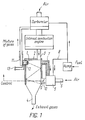
- the device for realization of the proposed method comprises a double-loop heat-exchanger 1 having a heat insulation 2, an intake piping 3 and an outlet piping 4 of hot exhaust gases of an internal combustion engine, a proportioner 5 of the components of the mixture provided with an air piping 6, an exhaust gas piping 7, and gasoline piping 8.
- the proportioner communicates, through a mixing nozzle 9, with the fuel-air mixture heating channel in the heat-exchange.
- a control member 10 is provided in the mixing nozzle to control the rate of flow of the mixture being prepared.
- a promoter 12 is situated at the heat-exchanger outlet or in an exhaust pipe 11, connected to an electric power source 13.
- the gasoline piping 8 is connected to the gasoline pump of the internal combustion engine which feeds the fuel to the carburetor.
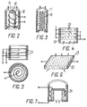
- the promoter 12 may be shaped as a cylinder 14 (FIG. 2) and a rod 15 accommodated in said cylinder coaxially therewith, both being made of a heat-resistant insulant, such as ceramics, and a single- or multiturn coil 16 wound onto the rod 15 and tightly laid between the cylinder and rod.
- a heat-resistant insulant such as ceramics
- the promoter 12 may also be made of a ceramic tube 17 (FIG. 3) accommodating a cluster of coils 18 wound together and tightly laid as along the direction of the mixture flow so that the cluster axis is parallel to the axis of the tube 17.
- the promoter 12 may also be made in the form of a number of zigzag- laid rows of wire 20 arranged consecutively in a housing 19 as along the mixture flow, the rays of the wire 20 intersecting in plan to establish a space net which can also be formed by several rows of parallel-coils 21 wound in plan into the Archimedean spiral (FIG. 5) and placed consecutively in a cylindrical housing.
- the well-developed heatable surface of the promoter 12 may be formed by a porous spatial element shaped as a flat solid 22 enclosed in a housing 23 (FIG. 6), or as a cylindrical solid 24 (FIG. 7).
- the device for preparing fuel-air mixture for internal combustion engines operates as follows.
- a very lean fuel-air mixture is prepared in the main fuel-air system of the engine with the aid of a carburetor.
- a mixture of combustible gases is prepared from an overrich fuel-air mixture ( ⁇ >0.45) in the auxiliary system consisting of the proportioner 5, the heat-exchanger 1, and the promoter 12, said overrich mixture compensating for fuel shortage in the mixture prepared in the main system so as to bring the fuel-air ratio to a normal for use in the internal combustion engine.
- the proportioner 5 With the internal combustion engine running, fed to the proportioner 5 along the respective pipings 6, 7, and 8 are air, part of the exhaust gases, and gasoline (e.g., in an amount of 10 - 20% of the total one).
- the proportioner 5 prepares a fuel-overrich mixture having an excess-air coefficient ⁇ not over 0.45.
- the heat exchanger may feature different flow patterns of gas currents.
- the preheated fuel-air mixture is fed to the hot surface of the promoter 12.
- Getting the fuel-air mixture particles in contact with the hot surface of the promoter 12 under oxidant shortage results partial oxidation of the molecules of an organic fuel (C8H18). It is as a result of such thermocontact cracking that the fuel molecules start decomposing.
- the original fuel molecules turn into a lighter structure to give rise to gases.
- thermocontact crackings proceeds more vigorously.
- a mixture of the resultant gases is fed along the pipe 11 to the intake engine manifold either directly or through the carburetor, to be mixed with the lean fuel-air mixture which feeds the internal combustion engine.
- a positive effect of the practical implementation of the present invention manifests itself in fuel economy, use of a cheaper low-octane fuel, and in a reduced (by a factor of ten to fifteen) CO content of the engine exhaust gases and a lower content of nitrogen oxides.
- the present invention can find application in the engine-building industry manufacturing both vehicle and stationary internal combustion engines and may be used in designing new such engines and in those now under exploitation. A possibility arises of using a low-octane fuel for engines designed to operate on a high-octane fuel.
Applications Claiming Priority (5)
| Application Number | Priority Date | Filing Date | Title |
|---|---|---|---|
| SU5002331 RU2008494C1 (ru) | 1991-09-18 | 1991-09-18 | Способ подготовки топливновоздушной смеси для двигателя внутреннего сгорания |
| SU5002331 | 1991-09-18 | ||
| SU5013677 | 1991-12-12 | ||
| SU5013677/06A RU2008495C1 (ru) | 1991-12-12 | 1991-12-12 | Устройство для обработки топливовоздушной смеси двигателя внутреннего сгорания |
| PCT/RU1992/000058 WO1993006358A1 (fr) | 1991-09-18 | 1992-03-26 | Procede et dispositif de preparation d'un melange d'air et de carburant pour moteur a combustion interne |
Publications (3)
| Publication Number | Publication Date |
|---|---|
| EP0557525A1 true EP0557525A1 (en) | 1993-09-01 |
| EP0557525A4 EP0557525A4 (en) | 1994-08-10 |
| EP0557525B1 EP0557525B1 (en) | 1998-02-04 |
Family
ID=26666260
Family Applications (1)
| Application Number | Title | Priority Date | Filing Date |
|---|---|---|---|
| EP92909946A Expired - Lifetime EP0557525B1 (en) | 1991-09-18 | 1992-03-26 | Method and device for preparation of fuel-air mixture for internal combustion engine |
Country Status (13)
| Country | Link |
|---|---|
| US (1) | US5327874A (es) |
| EP (1) | EP0557525B1 (es) |
| JP (1) | JP2778830B2 (es) |
| KR (1) | KR100232250B1 (es) |
| AT (1) | ATE163072T1 (es) |
| AU (1) | AU1682792A (es) |
| BR (1) | BR9205500A (es) |
| CA (1) | CA2095524C (es) |
| CZ (1) | CZ281303B6 (es) |
| DE (1) | DE69224371T2 (es) |
| ES (1) | ES2114559T3 (es) |
| FI (1) | FI103600B (es) |
| WO (1) | WO1993006358A1 (es) |
Cited By (1)
| Publication number | Priority date | Publication date | Assignee | Title |
|---|---|---|---|---|
| EP0773360A1 (en) * | 1995-11-02 | 1997-05-14 | TAG Co. LTD. | An exhaust gas purification system for a combustion apparatus |
Families Citing this family (9)
| Publication number | Priority date | Publication date | Assignee | Title |
|---|---|---|---|---|
| US5743242A (en) * | 1996-01-04 | 1998-04-28 | Phillips & Temro Industries Inc. | Air intake heater with connector posts |
| KR20010013078A (ko) | 1998-03-26 | 2001-02-26 | 알렉산드르 바실리에비체 프가체프 | 내연 기관용 연료-공기 혼합기의 조합 장치와 방법, 및 그장치에 이용되는 열교환기 |
| US7478628B2 (en) * | 2006-09-06 | 2009-01-20 | Hines James F | Vapor and liquid fuel injection system |
| US20080078364A1 (en) * | 2006-09-29 | 2008-04-03 | Sergey Antonov | Method and apparatus for increasing power of a diesel engine by continuously heating the fuel |
| US9957888B2 (en) * | 2016-03-30 | 2018-05-01 | General Electric Company | System for generating syngas and an associated method thereof |
| RU172392U1 (ru) * | 2016-07-18 | 2017-07-06 | федеральное государственное бюджетное образовательное учреждение высшего образования "Воронежский государственный университет" (ФГБОУ ВО "ВГУ") | Прибор обработки топлива |
| WO2018236229A1 (en) * | 2017-06-23 | 2018-12-27 | Selisana Elvis E | FUEL PREHEATING APPARATUS FOR INTERNAL COMBUSTION ENGINE |
| IL273222B1 (en) * | 2017-09-29 | 2024-01-01 | Res Triangle Inst | An internal combustion engine as a chemical reactor for the production of synthetic gas from a carbonaceous feed |
| RU181393U1 (ru) * | 2017-10-09 | 2018-07-11 | федеральное государственное бюджетное образовательное учреждение высшего образования "Воронежский государственный университет" (ФГБОУ ВО "ВГУ") | Прибор обработки топлива |
Family Cites Families (12)
| Publication number | Priority date | Publication date | Assignee | Title |
|---|---|---|---|---|
| BE786225A (fr) * | 1971-07-16 | 1973-01-15 | Siemens Ag | Procede pour le fonctionnement non polluant des machines a combustion interne et carburateur pour la mise en oeuvre du procede |
| JPS525643B2 (es) * | 1973-05-04 | 1977-02-15 | ||
| US3886919A (en) * | 1973-08-08 | 1975-06-03 | Allen M Freeman | Liquid fuel gasifier |
| US3945352A (en) * | 1974-10-16 | 1976-03-23 | Foundation For Research And Engineering Education | Fuel vaporization and injection system for internal combustion engine |
| GB1547252A (en) * | 1975-03-14 | 1979-06-06 | Little A | Fuel supply systems |
| JPS5831452B2 (ja) * | 1975-03-31 | 1983-07-06 | 日産自動車株式会社 | ネンシヨウキカン |
| US4151821A (en) * | 1976-12-06 | 1979-05-01 | Edward P Goodrum | Engine fuel supply system |
| US4249501A (en) * | 1979-08-06 | 1981-02-10 | Ewald Ehresmann | Fuel system for internal combustion engines |
| US4476840A (en) * | 1982-06-04 | 1984-10-16 | Budnicki Xavier B | Evaporation chamber for fuel delivery systems |
| DE3607007A1 (de) * | 1986-03-04 | 1987-09-10 | Metz Holger Dr | Vorrichtung zur thermischen spaltungsaufbereitung fluessiger brennstoffe fuer brennkraftmaschinen und betriebsverfahren fuer diese |
| US4930484A (en) * | 1989-10-26 | 1990-06-05 | Binkley Steven M | Fuel and air mixture expanding and preheating system |
| US5219399A (en) * | 1991-12-27 | 1993-06-15 | Brana Branislav V | Antipollution and fuel economy device and method for an internal combustion engine |
-
1992
- 1992-03-26 CA CA002095524A patent/CA2095524C/en not_active Expired - Fee Related
- 1992-03-26 WO PCT/RU1992/000058 patent/WO1993006358A1/ru active IP Right Grant
- 1992-03-26 JP JP4509043A patent/JP2778830B2/ja not_active Expired - Lifetime
- 1992-03-26 AU AU16827/92A patent/AU1682792A/en not_active Abandoned
- 1992-03-26 DE DE69224371T patent/DE69224371T2/de not_active Expired - Fee Related
- 1992-03-26 BR BR9205500A patent/BR9205500A/pt not_active IP Right Cessation
- 1992-03-26 CZ CZ93883A patent/CZ281303B6/cs not_active IP Right Cessation
- 1992-03-26 ES ES92909946T patent/ES2114559T3/es not_active Expired - Lifetime
- 1992-03-26 EP EP92909946A patent/EP0557525B1/en not_active Expired - Lifetime
- 1992-03-26 AT AT92909946T patent/ATE163072T1/de not_active IP Right Cessation
- 1992-06-30 US US08/064,101 patent/US5327874A/en not_active Expired - Fee Related
-
1993
- 1993-05-17 FI FI932228A patent/FI103600B/fi active
- 1993-05-18 KR KR1019930701475A patent/KR100232250B1/ko not_active IP Right Cessation
Non-Patent Citations (2)
| Title |
|---|
| No further relevant documents disclosed * |
| See also references of WO9306358A1 * |
Cited By (1)
| Publication number | Priority date | Publication date | Assignee | Title |
|---|---|---|---|---|
| EP0773360A1 (en) * | 1995-11-02 | 1997-05-14 | TAG Co. LTD. | An exhaust gas purification system for a combustion apparatus |
Also Published As
| Publication number | Publication date |
|---|---|
| AU1682792A (en) | 1993-04-27 |
| CZ281303B6 (cs) | 1996-08-14 |
| JPH07500392A (ja) | 1995-01-12 |
| FI103600B1 (fi) | 1999-07-30 |
| WO1993006358A1 (fr) | 1993-04-01 |
| ES2114559T3 (es) | 1998-06-01 |
| EP0557525A4 (en) | 1994-08-10 |
| FI932228A0 (fi) | 1993-05-17 |
| JP2778830B2 (ja) | 1998-07-23 |
| DE69224371T2 (de) | 1998-10-01 |
| KR930702606A (ko) | 1993-09-09 |
| BR9205500A (pt) | 1994-03-01 |
| CZ88393A3 (en) | 1993-11-17 |
| FI103600B (fi) | 1999-07-30 |
| EP0557525B1 (en) | 1998-02-04 |
| ATE163072T1 (de) | 1998-02-15 |
| DE69224371D1 (de) | 1998-03-12 |
| US5327874A (en) | 1994-07-12 |
| KR100232250B1 (en) | 2000-01-15 |
| FI932228A (fi) | 1993-05-17 |
| CA2095524C (en) | 1999-05-25 |
| CA2095524A1 (en) | 1993-03-19 |
Similar Documents
| Publication | Publication Date | Title |
|---|---|---|
| CA1070501A (en) | Hydrogen-rich gas generator | |
| US6302683B1 (en) | Catalytic combustion chamber and method for igniting and controlling the catalytic combustion chamber | |
| US6405720B1 (en) | Natural gas powered engine | |
| US20030233789A1 (en) | Method and apparatus for fuel/air preparation in a fuel cell | |
| US4350133A (en) | Cold start characteristics of ethanol as an automobile fuel | |
| WO1993018346A1 (en) | Fuel supply systems for engines and combustion processes therefor | |
| EP0557525B1 (en) | Method and device for preparation of fuel-air mixture for internal combustion engine | |
| US6314919B1 (en) | Method for preparing an air-fuel mixture for an internal combustion engine, device for realizing the same and heat-exchanger | |
| US5497617A (en) | Gas-enriched light-off | |
| US20100071263A1 (en) | Fuel reforming process for internal combustion engines | |
| JP2003529717A (ja) | 改善された放出性を有するガス駆動機関 | |
| RU2443764C1 (ru) | Способ работы устройства подготовки попутных нефтяных газов для использования в энергоустановках | |
| US4242076A (en) | Process of combustion | |
| JPS61171870A (ja) | 改質天然ガスを用いた内燃機関 | |
| Sjöström et al. | Onboard hydrogen generation for hydrogen injection into internal combustion engines | |
| RU2008495C1 (ru) | Устройство для обработки топливовоздушной смеси двигателя внутреннего сгорания | |
| RU2141054C1 (ru) | Способ подготовки топливовоздушной смеси для двигателя внутреннего сгорания и устройство для его осуществления | |
| JP3402505B2 (ja) | 燃料改質装置 | |
| RU2008494C1 (ru) | Способ подготовки топливновоздушной смеси для двигателя внутреннего сгорания | |
| RU99780U1 (ru) | Устройство подготовки попутных нефтяных газов для использования в энергоустановках | |
| CN117722269A (zh) | 一种氨内燃机系统及其控制方法 | |
| JPS5847240Y2 (ja) | 内燃機関用改質ガス発生装置 | |
| Houseman et al. | Hydrogen-rich gas generator | |
| Sendilvelan et al. | Thermal Analysis of Electrically Heated Catalyst to reduce Cold Start Emission from Gasoline engine | |
| Bunda et al. | Internal combustion engine with a methanol reforming system.[hydrocarbon-hydrogen fuel mixture] |
Legal Events
| Date | Code | Title | Description |
|---|---|---|---|
| PUAI | Public reference made under article 153(3) epc to a published international application that has entered the european phase |
Free format text: ORIGINAL CODE: 0009012 |
|
| 17P | Request for examination filed |
Effective date: 19930607 |
|
| AK | Designated contracting states |
Kind code of ref document: A1 Designated state(s): AT BE DE ES FR GB IT SE |
|
| A4 | Supplementary search report drawn up and despatched | ||
| AK | Designated contracting states |
Kind code of ref document: A4 Designated state(s): AT BE DE ES FR GB IT SE |
|
| 17Q | First examination report despatched |
Effective date: 19951025 |
|
| GRAG | Despatch of communication of intention to grant |
Free format text: ORIGINAL CODE: EPIDOS AGRA |
|
| GRAG | Despatch of communication of intention to grant |
Free format text: ORIGINAL CODE: EPIDOS AGRA |
|
| GRAH | Despatch of communication of intention to grant a patent |
Free format text: ORIGINAL CODE: EPIDOS IGRA |
|
| GRAH | Despatch of communication of intention to grant a patent |
Free format text: ORIGINAL CODE: EPIDOS IGRA |
|
| GRAA | (expected) grant |
Free format text: ORIGINAL CODE: 0009210 |
|
| AK | Designated contracting states |
Kind code of ref document: B1 Designated state(s): AT BE DE ES FR GB IT SE |
|
| REF | Corresponds to: |
Ref document number: 163072 Country of ref document: AT Date of ref document: 19980215 Kind code of ref document: T |
|
| REF | Corresponds to: |
Ref document number: 69224371 Country of ref document: DE Date of ref document: 19980312 |
|
| ITF | It: translation for a ep patent filed |
Owner name: MODIANO & ASSOCIATI S.R.L. |
|
| REG | Reference to a national code |
Ref country code: ES Ref legal event code: FG2A Ref document number: 2114559 Country of ref document: ES Kind code of ref document: T3 |
|
| ET | Fr: translation filed | ||
| PLBE | No opposition filed within time limit |
Free format text: ORIGINAL CODE: 0009261 |
|
| STAA | Information on the status of an ep patent application or granted ep patent |
Free format text: STATUS: NO OPPOSITION FILED WITHIN TIME LIMIT |
|
| 26N | No opposition filed | ||
| PGFP | Annual fee paid to national office [announced via postgrant information from national office to epo] |
Ref country code: GB Payment date: 19990224 Year of fee payment: 8 |
|
| PGFP | Annual fee paid to national office [announced via postgrant information from national office to epo] |
Ref country code: BE Payment date: 19990301 Year of fee payment: 8 |
|
| PGFP | Annual fee paid to national office [announced via postgrant information from national office to epo] |
Ref country code: AT Payment date: 19990310 Year of fee payment: 8 |
|
| PGFP | Annual fee paid to national office [announced via postgrant information from national office to epo] |
Ref country code: ES Payment date: 19990930 Year of fee payment: 8 |
|
| PG25 | Lapsed in a contracting state [announced via postgrant information from national office to epo] |
Ref country code: GB Free format text: LAPSE BECAUSE OF NON-PAYMENT OF DUE FEES Effective date: 20000326 Ref country code: AT Free format text: LAPSE BECAUSE OF NON-PAYMENT OF DUE FEES Effective date: 20000326 |
|
| PG25 | Lapsed in a contracting state [announced via postgrant information from national office to epo] |
Ref country code: ES Free format text: LAPSE BECAUSE OF NON-PAYMENT OF DUE FEES Effective date: 20000327 |
|
| PG25 | Lapsed in a contracting state [announced via postgrant information from national office to epo] |
Ref country code: BE Free format text: LAPSE BECAUSE OF NON-PAYMENT OF DUE FEES Effective date: 20000331 |
|
| BERE | Be: lapsed |
Owner name: PUGACHEV ALEXANDR VASILIEVICH Effective date: 20000331 |
|
| GBPC | Gb: european patent ceased through non-payment of renewal fee |
Effective date: 20000326 |
|
| PGFP | Annual fee paid to national office [announced via postgrant information from national office to epo] |
Ref country code: SE Payment date: 20010212 Year of fee payment: 10 |
|
| REG | Reference to a national code |
Ref country code: ES Ref legal event code: FD2A Effective date: 20011010 |
|
| PG25 | Lapsed in a contracting state [announced via postgrant information from national office to epo] |
Ref country code: SE Free format text: LAPSE BECAUSE OF NON-PAYMENT OF DUE FEES Effective date: 20020327 |
|
| PGFP | Annual fee paid to national office [announced via postgrant information from national office to epo] |
Ref country code: FR Payment date: 20020329 Year of fee payment: 11 |
|
| PGFP | Annual fee paid to national office [announced via postgrant information from national office to epo] |
Ref country code: DE Payment date: 20020418 Year of fee payment: 11 |
|
| EUG | Se: european patent has lapsed |
Ref document number: 92909946.3 |
|
| PG25 | Lapsed in a contracting state [announced via postgrant information from national office to epo] |
Ref country code: DE Free format text: LAPSE BECAUSE OF NON-PAYMENT OF DUE FEES Effective date: 20031001 |
|
| PG25 | Lapsed in a contracting state [announced via postgrant information from national office to epo] |
Ref country code: FR Free format text: LAPSE BECAUSE OF NON-PAYMENT OF DUE FEES Effective date: 20031127 |
|
| REG | Reference to a national code |
Ref country code: FR Ref legal event code: ST |
|
| PG25 | Lapsed in a contracting state [announced via postgrant information from national office to epo] |
Ref country code: IT Free format text: LAPSE BECAUSE OF NON-PAYMENT OF DUE FEES Effective date: 20050326 |