EP0557549A1 - Toroidal core transformer - Google Patents
Toroidal core transformer Download PDFInfo
- Publication number
- EP0557549A1 EP0557549A1 EP92103238A EP92103238A EP0557549A1 EP 0557549 A1 EP0557549 A1 EP 0557549A1 EP 92103238 A EP92103238 A EP 92103238A EP 92103238 A EP92103238 A EP 92103238A EP 0557549 A1 EP0557549 A1 EP 0557549A1
- Authority
- EP
- European Patent Office
- Prior art keywords
- winding
- toroidal
- core
- transformer according
- wound
- Prior art date
- Legal status (The legal status is an assumption and is not a legal conclusion. Google has not performed a legal analysis and makes no representation as to the accuracy of the status listed.)
- Granted
Links
Images


Classifications
-
- H—ELECTRICITY
- H01—ELECTRIC ELEMENTS
- H01F—MAGNETS; INDUCTANCES; TRANSFORMERS; SELECTION OF MATERIALS FOR THEIR MAGNETIC PROPERTIES
- H01F41/00—Apparatus or processes specially adapted for manufacturing or assembling magnets, inductances or transformers; Apparatus or processes specially adapted for manufacturing materials characterised by their magnetic properties
- H01F41/005—Impregnating or encapsulating
-
- H—ELECTRICITY
- H01—ELECTRIC ELEMENTS
- H01F—MAGNETS; INDUCTANCES; TRANSFORMERS; SELECTION OF MATERIALS FOR THEIR MAGNETIC PROPERTIES
- H01F30/00—Fixed transformers not covered by group H01F19/00
- H01F30/06—Fixed transformers not covered by group H01F19/00 characterised by the structure
- H01F30/16—Toroidal transformers
Definitions
- the invention relates to a method for producing a cast power resin cast with a wound cutting tape core, preferably made of a cold-rolled ferro alloy, which has a magnetic preferential direction, and a toroidal transformer produced by this method.
- Modern ferro alloys for the production of transformer sheets consisting essentially of iron / nickel or iron / silicon alloys, have very good magnetic properties which make it possible to construct transformers with correspondingly good electrical values, but are very difficult to process. Shall the good magnetic Properties of these transformer sheets are exploited, the magnetic preferred direction with the main flow direction in the transformer sheet must match as much as possible. This means that, for example, normal M-cuts cannot be used, but that with a three-column transformer, the preferred magnetic direction in the yokes must be perpendicular to that in the cores. In addition, the core and yoke sheets must be mitred to largely keep the flow direction in the preferred direction of the sheets.
- Toroidal transformers have been known for a long time, in which the transformer sheet, which is in tape form, is wound in a ring and then this toroid is wound with transformer coils. With such a toroidal transformer, the difficulties described above do not arise, since the direction of flow in the transformer sheet always corresponds to its preferred magnetic direction. Difficulties arise with such toroidal transformers due to the application of the windings special special winding machines. Toroidal transformers and chokes have therefore so far only been built for small outputs. Grid power transformers with this structure have not yet been disclosed.
- cutting band cores are also used which, like the toroidal core transformers, have a wound core, but usually wound in an approximate rectangular shape, which is cut at two points transversely to the longitudinal direction of the metal sheets. This makes it possible to place previously manufactured spools on the straight parts of these cut ribbon cores wound in a rectangular shape and then to bring the two core halves together again with the smallest possible air gap. This eliminates the difficulty of winding such cores, which also have extremely good electrical properties.
- only low-power transformers equipped with such cutting tape cores have so far become known.
- the toroidal transformer according to the invention thus differs from the known toroidal transformers with a ribbon core in that it does not have a rectangular wound core like this, but this winding core is circular.
- This has the disadvantage, ostensibly, that no cylindrical coils can be pushed onto the winding core, but that, and that probably prevented the experts from using such round winding cores, the winding and sliding on of the coils could be difficult. In fact this is not the case, if so, as by the Invention is set forth, since the low-voltage coil with its relatively thick wire cross-section pre-wound as an air coil and then can be pushed over the half-arch of the cut core without difficulty.
- the winding disks should not exceed a disk width of 40 degrees of arc of the inner ring core diameter, in particular to enable the individual winding disks to be pushed over the ring core.
- the disc-shaped design of the high-voltage winding not only avoids the difficulties in moving the winding parts onto the toroid, but also does not result in any insulation problems, since these winding disks each have only a limited voltage range for the entire high-voltage coil have to record.
- the arrangement of the individual winding disks can also be adapted to the respective requirements, that is to say individual winding disks can be combined to form disk segments or symmetrical distances can also be set.
- the hardened toroidal core is coated with an elastically flexible insulating material.
- This insulation material not only represents an electrical insulation layer to the toroid, but also enables a certain amount of heat to move both the toroid and the low-voltage coil pushed onto the toroid.
- This insulation layer is therefore an important feature of the invention, since it has been shown that with such transformers of greater output, the removal of the heat generated in these compactly constructed transformers can cause difficulties and therefore leads to thermal movements of the individual components. Since the casting resin into which the toroidal core transformer is cast can be considered rigid, such thermal movements, due to the different coefficients of thermal expansion of the different materials, ultimately lead to microcracks within the casting resin, which can lead to a change in the electrical field or to electrical breakdown .
- the complete encapsulation of the transformer according to the invention has the advantage of extraordinary noise insulation. This becomes one causes that all parts of the transformer - iron core, low-voltage and high-voltage coil - are firmly embedded in the casting resin, on the other hand in that the casting resin forms a sound-absorbing layer around the transformer. However, this complete pouring is only possible through the insulating material layer inserted according to the invention.
- a silicone is proposed as the preferred insulating material, which can be constructed to be both elastic and flexible with good electrical and thermal properties.
- winding disks of the high-voltage winding are usually wound in such a way that disks with a constant width result.
- Such a winding can be produced with the modern automatic winding machines without difficulty.
- the transformer according to the invention can also be equipped with diodes for rectification.
- diodes assigned to each winding disk are arranged on or in the outwardly projecting casting ribs.
- the diodes are expediently accommodated in a vertical air shaft provided on the ribs. This has the advantage that the diodes against mechanical damage is protected, that it is accessible and therefore easily replaceable and that you are also sufficiently cooled by the air flow resulting in this air shaft.
- there are also advantageous electrical voltage ratios since each diode or diode arrangement is only acted upon by the partial voltage of a single winding disk.
- the single-phase transformers constructed in this way can be connected in the usual way to three-phase transformers standing side by side.
- a particularly expedient embodiment results from the fact that the three individual transformers are placed on top of one another to form an “energy column” and anchored in this position. This not only brings spatial advantages, but also good heat dissipation through the rib-shaped parts of the transformers arranged one above the other.
- the anchoring is carried out in such a way that the individual transformer blocks can also be displaced in the vertical direction in order to compensate for the thermal movements.
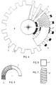
- the toroidal transformer shown has a circularly wound toroid (1), which is divided into two halves by two cuts (2).
- Low-voltage coils (3) which were previously manufactured as air coils, are pushed onto these two ring halves, as shown in FIG. 9.
- an elastic, flexible insulation layer (4) Between the low-voltage coil (3) and the toroidal core (1) there is an elastic, flexible insulation layer (4).
- the two halves of the ring core are each cast separately, although the cut surfaces (2) of the ring cores are still free.
- support elements (8) are then placed on the low-voltage coil (3) when the toroidal halves finished to the low-voltage coil are not cast.
- These support elements determine the position of the high-voltage coils (5, 15) to be pushed on.
- the high-voltage coils (5 and 15) are then pushed over the ring core halves, as can be seen from FIGS. 4 and 5.
- the two toroid halves are on their cut surfaces pressed together and, for example by surface welding, fixed in this position and then cast with casting resin (6).
- the protruding winding disks of the high-voltage windings (5) give rise to ribs (7) which provide good ventilation for the toroidal transformer thus constructed.
- Fig. 10 finally shows an "energy column” formed from three superimposed single toroidal transformers, which are held in this position by a central pressure rod (9) and a resilient clamping ring (8).
Abstract
Description
Die Erfindung betrifft ein Verfahren zum Herstellen eines mit Gießharz vergossenen Netz-Leistungstransformators mit einem gewickelten Schnittbandkern, vorzugsweise aus einer kaltgewalzten Ferrolegierung, die eine magnetische Vorzugsrichtung aufweist, sowie einen nach diesem Verfahren hergestellten Ringkerntransformator.The invention relates to a method for producing a cast power resin cast with a wound cutting tape core, preferably made of a cold-rolled ferro alloy, which has a magnetic preferential direction, and a toroidal transformer produced by this method.
Moderne Ferrolegierungen zur Herstellung von Transformatorenblechen, im wesentlichen bestehend aus Eisen/ Nickel- oder Eisen/Silicium-Legierungen, weisen zwar sehr gute magnetische Eigenschaften auf die es erlauben, Transformatoren mit entsprechend guten elektrischen Werten aufzubauen, sind jedoch in ihrer Verarbeitung sehr schwierig. Sollen die guten magnetischen Eigenschaften dieser Transformatorenbleche ausgenutzt werden, muß die magnetische Vorzugsrichtung mit der Haupt-Flußrichtung im Transformatorenblech möglichst weitgehend übereinstimmen. Dies bedeutet, daß beispielsweise keine normalen M-Schnitte eingesetzt werden können, sondern daß bei einem Drei-Säulen-Transformator die magnetische Vorzugsrichtung in den Jochen senkrecht zu denjenigen in den Kernen liegen muß. Außerdem müssen die Kern- und Jochbleche auf Gehrung geschnitten werden, um weitgehend die Flußrichtung in der Vorzugsrichtung der Bleche zu halten. Das Zuschneiden der Bleche mit einer speziellen Blechschneidemaschine mit Schrägschnitteinrichtung, wie auch insbesondere das notwendige, sorgsame Schichten der Transformatorenbleche, ist außerordentlich zeitaufwendig und lohnintensiv. Damit ergibt sich, daß mit diesen Transformatorenblechen aufgebaute Transformatoren zwar zufriedenstellende elektrische Eigenschaften aufweisen, aber verhältnismäßig teuer sind. Hinzu kommt bei den üblichen Blechschnitten noch das große Volumen und hohe Gewicht solcher Transformatoren, was zu Schwierigkeiten bei deren Aufstellung führen kann.Modern ferro alloys for the production of transformer sheets, consisting essentially of iron / nickel or iron / silicon alloys, have very good magnetic properties which make it possible to construct transformers with correspondingly good electrical values, but are very difficult to process. Shall the good magnetic Properties of these transformer sheets are exploited, the magnetic preferred direction with the main flow direction in the transformer sheet must match as much as possible. This means that, for example, normal M-cuts cannot be used, but that with a three-column transformer, the preferred magnetic direction in the yokes must be perpendicular to that in the cores. In addition, the core and yoke sheets must be mitred to largely keep the flow direction in the preferred direction of the sheets. Cutting the sheets with a special sheet metal cutting machine with angled cutting device, as well as, in particular, the necessary, careful layering of the transformer sheets, is extremely time-consuming and cost-intensive. This means that transformers constructed with these transformer sheets have satisfactory electrical properties, but are relatively expensive. Added to this is the large volume and weight of such transformers in conventional sheet metal cuts, which can lead to difficulties in their installation.
Seit längerer Zeit sind schon Ringkerntransformatoren bekannt, bei denen das in Bandform vorliegende Transformatorenblech in einem Ring gewickelt und sodann dieser Ringkern mit Transformatorenspulen bewickelt wird. Bei einem solchen Ringkerntransformator entstehen die oben geschilderten Schwierigkeiten nicht, da stets die Flußrichtung im Transformatorenblech mit dessen magnetischer Vorzugsrichtung übereinstimmt. Schwierigkeiten bereiten bei solchen Ringkerntransformatoren jedoch das Aufbringen der Wicklungen durch besondere Spezial-Wickelmaschinen. Ringkerntransformatoren und -Drosseln wurden daher bisher nur für kleine Leistungen gebaut. Netz-Leistungstransformatoren mit diesem Aufbau sind bisher nicht bekanntgeworden.Toroidal transformers have been known for a long time, in which the transformer sheet, which is in tape form, is wound in a ring and then this toroid is wound with transformer coils. With such a toroidal transformer, the difficulties described above do not arise, since the direction of flow in the transformer sheet always corresponds to its preferred magnetic direction. Difficulties arise with such toroidal transformers due to the application of the windings special special winding machines. Toroidal transformers and chokes have therefore so far only been built for small outputs. Grid power transformers with this structure have not yet been disclosed.
Ausgehend von diesen Ringkerntransformatoren beziehungsweise Ringkerndrosseln werden auch Schnittbandkerne eingesetzt, die ebenfalls wie bei den Ringkerntransformatoren einen gewickelten, üblicherweise jedoch in angenäherter Rechteckform gewickelten Kern aufweisen, der an zwei Stellen quer zur Längsrichtung der Bleche zerschnitten ist. Dadurch wird es ermöglicht, zuvor gefertigte Spulen auf die geraden Teile dieser in Rechteckform gewickelten Schnittbandkerne aufzustecken und die beiden Kernhälften anschließend mit möglichst geringem Luftspalt wieder aufeinander zu bringen. Damit ist die Schwierigkeit des Bewickelns derartiger Kerne, die ebenfalls äußerst gute elektrische Eigenschaften aufweisen, behoben. Allerdings sind bisher auch nur mit derartigen Schnittbandkernen ausgestattete Transformatoren für geringe Leistungen bekanntgeworden.Starting from these toroidal core transformers or toroidal core chokes, cutting band cores are also used which, like the toroidal core transformers, have a wound core, but usually wound in an approximate rectangular shape, which is cut at two points transversely to the longitudinal direction of the metal sheets. This makes it possible to place previously manufactured spools on the straight parts of these cut ribbon cores wound in a rectangular shape and then to bring the two core halves together again with the smallest possible air gap. This eliminates the difficulty of winding such cores, which also have extremely good electrical properties. However, only low-power transformers equipped with such cutting tape cores have so far become known.
Aufgabe der Erfindung ist es, die guten Eigenschaften solcher Ringkerntransformatoren mit Schnittbandkernen auch für Transformatoren und Drosseln verhältnismäßig hoher Leistung auszunutzen, mit solchen Kernen also auch Netz-Leistungstransformatoren aufbauen zu können. Erreicht wird dies in erfindungsgemäßer Weise, ausgehend von einem in der magnetischen Vorzugsrichtung spiralförmig gewickelten Band, das durch Harzbeigabe zu einem runden Ringkern verfestigt wurde durch folgende teilweise bekannte Verfahrensschritte:
- 1. Beschichten des Ringkerns mit einer elektrisch isolierenden, jedoch wärmeleitfähigen und wärmebeständigen, elastisch-nachgiebigen Dämmstofflage;
- 2. Zerschneiden des Ringkerns in zwei Ringhälften;
- 3.
- a) Überschieben einer Niederspannungs-Rechteckwicklung aus lackisoliertem Rund-, Rechteck- oder Profildraht auf jeweils eine Ringhälfte;
- b) gegebenenfalls Überschieben einer oder weiterer Rechteckwicklungen auf die jeweils zuvor aufgebrachte Wicklung;
- 4.
- a) Vergießen der bewickelten Ringkernhälften oder
- b) Aufbringen von aus Gießharz gefertigten Stützelementen;
- 5. Überschieben von jeweils zusammengefügten Hochspannungs-Wicklungsscheiben;
- 6. Zusammenfügen der beiden Ringkernhälften;
- 7. Verbinden oder Herausführen der Wicklungsenden;
- 8. Vergießen des kompletten Transformators mit rippenartigem Umgießen der Wicklungsscheiben.
- 1. Coating the toroidal core with an electrically insulating, but heat-conductive and heat-resistant, resilient insulation layer;
- 2. Cut the toroid into two halves;
- 3rd
- a) pushing a low-voltage rectangular winding made of enamelled round, rectangular or profile wire onto one half of the ring;
- b) if necessary, pushing one or more rectangular windings onto the respective previously applied winding;
- 4th
- a) casting the wound toroid halves or
- b) applying supporting elements made of cast resin;
- 5. Pushing over each of the assembled high-voltage winding disks;
- 6. Join the two toroid halves;
- 7. Connect or lead out the winding ends;
- 8. Casting the complete transformer with rib-like casting around the winding disks.
Der Ringkerntransformator nach der Erfindung unterscheidet sich damit von den bekannten Ringkerntransformatoren mit Schnittbandkern dadurch, daß er nicht wie diese einen rechteckförmig gewickelten Kern aufweist, sondern dieser Wickelkern kreisrund ist. Dies hat zwar vordergründig den Nachteil, daß keine zylinderförmigen Spulen auf den Wickelkern aufgeschoben werden können, sondern daß, und das hielt wahrscheinlich die Fachwelt von der Verwendung derartiger runder Wickelkerne ab, das Wickeln und Aufschieben der Spulen Schwierigkeiten bereiten könnte. Tatsächlich ist dies nicht der Fall, wenn so, wie durch die Erfindung dargelegt, vorgegangen wird, da die Niederspannungsspule mit aus Ihrem verhältnismäßig dicken Drahtquerschnitt als Luftspule vorgewickelt und sodann ohne Schwierigkeiten über den Halbbogen des zerschnittenen Kerns übergeschoben werden kann. Auch das Überschieben weiterer Niederspannungswicklungen über die jeweils zuvor aufgebrachte Wicklung bereitet, wie die Praxis gezeigt hat, absolut keine Schwierigkeiten, so daß der bisherige Einwand gegen Ringkerntransformatoren mit rundgewickeltem Ringkern widerlegt ist. Das Aufschieben der Hochspannungsspulen gelingt allerdings nicht auf diese Art und Weise. Diese Hochspannungswicklung müßte tatsächlich halbkreisförmig gewickelt werden, was wiederum eine Spezial-Wickelmaschine voraussetzen würde. Außerdem könnten bei einer solchen Hochspannungspule Isolationsprobleme entstehen. Diese Schwierigkeiten werden nach der Erfindung dadurch umgangen, daß die Hochspannungsspule in einzelne, verhältnismäßig dünne Wicklungsscheiben unterteilt wird, die nun ohne Schwierigkeiten auf normalen Wickelmaschinen zu wickeln und ebenfalls ohne Schwierigkeiten auf den zuvor umgossenen oder mit Stützelementen versehenen Ringkern aufgeschoben werden können. Hierbei sollen die Wicklungsscheiben eine Scheibenbreite von 40 Bogengrad des inneren Ringkerndurchmessers nicht überschreiten, um insbesondere das Überschieben der einzelnen Wicklungsscheiben über den Ringkern zu ermöglichen. Durch die scheibenförmige Ausbildung der Hochspannungswicklung werden jedoch nicht nur die Schwierigkeiten beim Überschieben der Wicklungsteile auf den Ringkern vermieden, sondern es ergeben sich dadurch auch keine Isolationsprobleme, da diese Wicklungsscheiben jeweils nur einen begrenzten Spannungsbereich der gesamten Hochspannungsspule aufzunehmen haben. Selbstverständlich kann hierbei auch die Anordnung der einzelnen Wicklungsscheiben den jeweiligen Erfordernissen angepaßt, es können also einzelne Wicklungsscheiben zu Scheibensegmenten zusammengefaßt oder auch symetrische Abstände eingestellt werden. Ein außerordentlicher weiterer Vorteil ist darin zu erblicken, daß derartige Transformatoren nunmehr mit einzelnen Modulen aufgebaut werden können, da das Anpassen der Hochspannungsspule an die jeweils vorliegende Spannung einfach durch Aufstecken mehr oder weniger derartiger Wicklungsscheiben durchgeführt werden kann. Diese Modulbauweise erlaubt die rationelle Herstellung großer Stückzahlen gleichartiger Bauteile und damit deren und selbstverständlich auch der Transformatoren wirtschaftliche Produktion. Außerdem können die Wicklungsenden dieser Scheibenwicklungen auch nach außen geführt werden, so daß deren Verschaltung auch außerhalb des Transformators vorgenommen werden kann. Ein weiterer, beachtlicher Vorzug derartiger Transformatoren ergibt sich durch ihr geringes Gewicht und ihr kleines Volumen. Tatsächlich finden sich in einem solchen Ringkerntransformator ja nahezu nur die Teile, die ein solcher Transformator benötigt, also die Primär- und die Sekundärspule sowie das in idealer Weise aufgewickelte Transformatorenblech. Umfassende Joche oder Blechstege wie bei den üblichen Transformatoren entfallen vollkommen und damit auch deren Volumen und deren Gewicht. Beachtlich ist selbstverständlich auch die Gewichtseinsparung durch den Wegfall eines umgebenden Mantels, da der mit Gießharz vergossene Transformator einen solchen Mantel nicht mehr benötigt.The toroidal transformer according to the invention thus differs from the known toroidal transformers with a ribbon core in that it does not have a rectangular wound core like this, but this winding core is circular. This has the disadvantage, ostensibly, that no cylindrical coils can be pushed onto the winding core, but that, and that probably prevented the experts from using such round winding cores, the winding and sliding on of the coils could be difficult. In fact this is not the case, if so, as by the Invention is set forth, since the low-voltage coil with its relatively thick wire cross-section pre-wound as an air coil and then can be pushed over the half-arch of the cut core without difficulty. Also, as practice has shown, pushing additional low-voltage windings over the respective previously applied winding presents absolutely no difficulties, so that the previous objection to toroidal transformers with a round-wound toroid is refuted. However, the high-voltage coils cannot be pushed on in this way. This high-voltage winding would actually have to be wound in a semicircle, which in turn would require a special winding machine. In addition, insulation problems could arise with such a high-voltage coil. These difficulties are avoided according to the invention in that the high-voltage coil is divided into individual, relatively thin winding disks, which can now be wound without difficulty on normal winding machines and can also be easily pushed onto the ring core previously cast or provided with support elements. In this case, the winding disks should not exceed a disk width of 40 degrees of arc of the inner ring core diameter, in particular to enable the individual winding disks to be pushed over the ring core. The disc-shaped design of the high-voltage winding not only avoids the difficulties in moving the winding parts onto the toroid, but also does not result in any insulation problems, since these winding disks each have only a limited voltage range for the entire high-voltage coil have to record. Of course, the arrangement of the individual winding disks can also be adapted to the respective requirements, that is to say individual winding disks can be combined to form disk segments or symmetrical distances can also be set. An extraordinary further advantage can be seen in the fact that such transformers can now be constructed with individual modules, since the adaptation of the high-voltage coil to the current voltage can be carried out simply by plugging in more or less such winding disks. This modular design enables the rational production of large numbers of similar components and thus their and of course the economical production of transformers. In addition, the winding ends of these disk windings can also be guided to the outside, so that they can also be connected outside the transformer. Another remarkable advantage of such transformers is their light weight and small volume. In fact, such a toroidal transformer almost only contains the parts that such a transformer requires, that is, the primary and secondary coils and the transformer sheet wound in an ideal manner. Comprehensive yokes or sheet metal webs as with the usual transformers are completely eliminated, and with it their volume and weight. Of course, the weight savings due to the omission of a surrounding jacket is also remarkable, since the transformer cast with cast resin no longer needs such a jacket.
Nach dem Verfahrensschritt 4 wird der ausgehärtete Ringkern mit einem elastisch-nachgiebigen Dämmstoff beschichtet. Dieser Dämmstoff stellt nicht nur eine elektrische Isolationsschicht zu dem Ringkern dar, sondern ermöglicht auch eine gewisse Wärmebewegung sowohl des Ringkerns wie auch der auf den Ringkern aufgeschobenen Niederspannungsspule. Damit ist diese Dämmschicht ein wichtiges Erfindungsmerkmal, da sich gezeigt hat, daß bei derartigen Transformatoren größerer Leistung der Abtransport der in diesen kompakt gebauten Transformatoren entstehenden Wärme Schwierigkeiten bereiten kann und daher zu Wärmebewegungen der einzelnen Bauteile führt. Da das Gießharz, in das der Ringkerntransformator eingegossen ist, als starr gelten kann, führen derartige Wärmebewegungen, bedingt durch die unterschiedlichen Wärme-Ausdehnungskoeffizienten der verschiedenen Materialien letztlich zu Mikrorissen innerhalb des Gießharzes, die zu einer Änderung des elektrischen Feldes beziehungsweise zum elektrischen Durchschlag führen kann. Bei dem erfindungsgemäß aufgebauten Ringkerntransformator hingegen werden diese im Inneren des Ringkerntransformators sich ergebenden Wärmebewegungen durch die elastischnachgiebige Dämmschicht aufgenommen, praktisch ohne Einwirkung auf den umgebenden Gießharzmantel. Tatsächlich hat die Praxis auch gezeigt, daß derart aufgebaute Transformatoren frei von solchen gefährlichen Mikrorissen sind.After
Hingewiesen werden darf in diesem Zusammenhang auch darauf, daß das komplette Vergießen des erfindungsgemäßen Transformators den Vorteil einer außerordentlichen Geräuschdämmung mit sich bringt. Dies wird zum einen dadurch bewirkt, daß sämtliche Teile des Transformators - Eisenkern, Niederspannungs- und Hochspannungsspule - fest im Gießharz eingebettet sind, zum anderen auch dadurch, daß das Gießharz eine schalldämmende Schicht um den Transformator bildet. Dieses komplette Eingießen ist allerdings nur durch die erfindungsgemäß eingefügte Dämmstoffschicht möglich.In this context, it should also be pointed out that the complete encapsulation of the transformer according to the invention has the advantage of extraordinary noise insulation. This becomes one causes that all parts of the transformer - iron core, low-voltage and high-voltage coil - are firmly embedded in the casting resin, on the other hand in that the casting resin forms a sound-absorbing layer around the transformer. However, this complete pouring is only possible through the insulating material layer inserted according to the invention.
Als bevorzugter Dämmstoff wird ein Silikon vorgeschlagen, das sowohl elastisch-nachgiebig aufgebaut werden kann bei guten elektrischen und thermischen Eigenschaften.A silicone is proposed as the preferred insulating material, which can be constructed to be both elastic and flexible with good electrical and thermal properties.
Die Wicklungsscheiben der Hochspannungswicklung werden üblicherweise so gewickelt, daß sich Scheiben mit gleichbleibender Breite ergeben. Um das Volumen derartiger Ringkerntransformatoren jedoch voll ausnutzen zu können, kann es auch zweckmäßig sein, diese Scheiben keilförmig zu wickeln, also daß die zum Zentrum des Ringkerns weisenden Seiten mit geringerer Breite ausgeführt werden als auf der Gegenseite. Eine solche Wicklung ist ohne Schwierigkeiten mit den modernen Wickelautomaten herzustellen.The winding disks of the high-voltage winding are usually wound in such a way that disks with a constant width result. However, in order to be able to fully utilize the volume of such toroidal transformers, it may also be expedient to wrap these disks in a wedge shape, that is to say that the sides facing the center of the toroidal core are made narrower than on the opposite side. Such a winding can be produced with the modern automatic winding machines without difficulty.
Der Transformator nach der Erfindung kann, wird hochgespannte Gleichspannung benötigt, auch gleich mit Dioden zur Gleichrichtung bestückt werden. Dies kann nach der Erfindung so erfolgen, daß an oder in den nach außen abstehenden Vergußrippen jeder Wicklungsscheibe zugeordnete Dioden angeordnet sind. Zweckmäßigerweise werden die Dioden hierbei in einem senkrechten an den Rippen vorgesehenen Luftschacht untergebracht. Dies hat den Vorteil, daß die Dioden gegen mechanische Beschädigungen geschützt sind, daß sie zugänglich und damit leicht auswechselbar sind und daß Sie außerdem durch den sich in diesem Luftschacht ergebenden Luftstrom ausreichend gekühlt sind. Zu diesen Vorteilen ergeben sich auch noch vorteilhafte elektrische Spannungsverhältnisse, da jede Diode beziehungsweise Diodenanordnung jeweils nur von der Teilspannung einer einzigen Wicklungsscheibe beaufschlagt wird.If high-voltage DC voltage is required, the transformer according to the invention can also be equipped with diodes for rectification. This can be done according to the invention in such a way that diodes assigned to each winding disk are arranged on or in the outwardly projecting casting ribs. The diodes are expediently accommodated in a vertical air shaft provided on the ribs. This has the advantage that the diodes against mechanical damage is protected, that it is accessible and therefore easily replaceable and that you are also sufficiently cooled by the air flow resulting in this air shaft. In addition to these advantages, there are also advantageous electrical voltage ratios, since each diode or diode arrangement is only acted upon by the partial voltage of a single winding disk.
Selbstverständlich können die so aufgebauten Einphasentransformatoren in üblicher Weise zu nebeneinander stehenden Drehstromtransformatoren verschaltet werden. Eine besonders zweckmäßige Ausführung ergibt sich dadurch, daß die drei Einzeltransformatoren zu einer "Energiesäule" aufeinander gestellt und in dieser Lage verankert werden. Diese bringt nicht nur räumliche Vorteile, sondern auch eine gute Wärmeabführung durch die übereinander angeordneten rippenförmigen Teile der Transformatoren. Die Verankerung wird hierbei so vorgenommen, daß auch in vertikaler Richtung ein Verschieben der einzelnen Transformatorenblöcke möglich ist, um auch hier die Wämebewegungen auszugleichen.Of course, the single-phase transformers constructed in this way can be connected in the usual way to three-phase transformers standing side by side. A particularly expedient embodiment results from the fact that the three individual transformers are placed on top of one another to form an “energy column” and anchored in this position. This not only brings spatial advantages, but also good heat dissipation through the rib-shaped parts of the transformers arranged one above the other. The anchoring is carried out in such a way that the individual transformer blocks can also be displaced in the vertical direction in order to compensate for the thermal movements.
Auf der Zeichnung ist der Erfindungsgegenstand schematisch dargestellt, und zwar zeigen:
- Fig. 1
- eine perspektivische Darstellung, teilweise geschnitten,
- Fig. 2
- die Draufsicht
und - Fig. 3
- die Seitenansicht eines gewickelten Ringbandkernes,
- Fig. 4
- eine erste
und - Fig. 5
- eine zweite mögliche Spulenanordnung,
- Fig. 6
- eine Draufsicht, teilweise geschnitten,
- Fig. 7
- eine vorgewickelte Niederspannungsspule in Ansicht
und - Fig. 8
- im Querschnitt
und - Fig. 9
- eine teilweise auf einen Halb-Ringkern aufgeschobene Niederspannnungsspule.
- Fig. 10
- eine "Energiesäule"
- Fig. 1
- a perspective view, partially cut,
- Fig. 2
- the top view
and - Fig. 3
- the side view of a wound toroidal core,
- Fig. 4
- a first
and - Fig. 5
- a second possible coil arrangement,
- Fig. 6
- a top view, partially cut,
- Fig. 7
- a pre-wound low voltage coil in view
and - Fig. 8
- in cross section
and - Fig. 9
- a low-voltage coil partially pushed onto a half toroid.
- Fig. 10
- an "energy pillar"
Der dargestellte Ringkerntransformator weist einen kreisrund gewickelten Ringkern (1) auf, der durch zwei Schnitte (2) in zwei Ringhälften geteilt ist. Auf diese beiden Ringhälften werden Niederspannungsspulen (3), die zuvor als Luftspulen gefertigt wurden, aufgeschoben, wie dies Fig. 9 zeigt. Zwischen der Niederspannungsspule (3) und dem Ringkern (1) befindet sich eine elastisch-nachgiebige Dämmschicht (4). Nach diesen Arbeiten werden die beiden Ringkernhälften jeweils für sich vergossen, wobei allerdings die Schnittflächen (2) der Ringkerne noch freibleiben. Eingezeichnet (Fig. 1) sind auch noch Stützelemente (8), die dann auf die Niederspannungsspule (3) aufgesetzt werden, wenn die bis zur Niederspannungsspule fertiggestellten Ringkernhälften nicht vergossen werden. Diese Stützelemente, aus dem gleichen Gießharz der zum kompletten Vergießen des Transformators Verwendung finden, bestimmen hierbei die Lage der aufzuschiebenden Hochspannungsspulen (5, 15). Danach werden die Hochspannungsspulen (5 beziehungsweise 15) über die Ringkernhälften übergeschoben, wie dies aus den Fig. 4 und 5 ersichtlich ist. Nach diesen Arbeiten werden die beiden Ringkernhälften an ihren Schnittflächen zusammengepreßt und, beispielsweise durch oberflächiges Verschweißen, in dieser Lage fixiert und sodann mit Gießharz (6) vergossen. Beim Vergießen ergeben sich durch die abstehenden Wicklungsscheiben der Hochspannungswicklungen (5) Rippen (7), die einer guten Belüftung des so aufgebauten Ringkerntransformators dienen.The toroidal transformer shown has a circularly wound toroid (1), which is divided into two halves by two cuts (2). Low-voltage coils (3), which were previously manufactured as air coils, are pushed onto these two ring halves, as shown in FIG. 9. Between the low-voltage coil (3) and the toroidal core (1) there is an elastic, flexible insulation layer (4). After this work, the two halves of the ring core are each cast separately, although the cut surfaces (2) of the ring cores are still free. Also shown (Fig. 1) are support elements (8), which are then placed on the low-voltage coil (3) when the toroidal halves finished to the low-voltage coil are not cast. These support elements, made of the same casting resin that is used to completely cast the transformer, determine the position of the high-voltage coils (5, 15) to be pushed on. The high-voltage coils (5 and 15) are then pushed over the ring core halves, as can be seen from FIGS. 4 and 5. After this work, the two toroid halves are on their cut surfaces pressed together and, for example by surface welding, fixed in this position and then cast with casting resin (6). During casting, the protruding winding disks of the high-voltage windings (5) give rise to ribs (7) which provide good ventilation for the toroidal transformer thus constructed.
Fig. 10 zeigt schließlich noch eine "Energiesäule" gebildet aus drei übereinandergesetzten Einzel-Ringkerntransformatoren, die durch einen zentralen Druckstab (9) und einen federnden Spannring (8) in dieser Lage gehalten sind.Fig. 10 finally shows an "energy column" formed from three superimposed single toroidal transformers, which are held in this position by a central pressure rod (9) and a resilient clamping ring (8).
Claims (7)
durch folgende teilweise bekannte Verfahrensschritte:
through the following partially known process steps:
dadurch gekennzeichnet,
daß der Dämmstoff ein Silicon ist.Toroidal transformer according to claim 1,
characterized,
that the insulation is a silicone.
dadurch gekennzeichnet,
daß das Silikon hinsichtlich seines Ausdehnungskoeffizienten auf den Temperatur-Ausdehnungskoeffizienten des Ferromaterials oder des Wicklungsmaterials eingestellt ist;Toroidal transformer according to claim 1,
characterized,
that the silicone is adjusted with regard to its coefficient of expansion to the coefficient of thermal expansion of the ferromaterial or the winding material;
dadurch gekennzeichnet,
daß die Wicklungsscheibenbreite ≦ 40 Bogengrad des inneren Ringkerndurchmessers ist.Toroidal transformer according to claim 1,
characterized,
that the winding disc width ≦ 40 degrees of arc of the inner ring core diameter.
dadurch gekennzeichnet,
daß die Seitenflächen der Wicklungsscheiben (5) in einem spitzen Winkel verlaufen.Toroidal transformer according to claim 1 or 4,
characterized,
that the side surfaces of the winding disks (5) run at an acute angle.
dadurch gekennzeichnet,
daß an den nach außen abstehenden Vergußrippen (7) jeder Wicklungsscheibe (5,15) Lüftungkanäle zur Aufnahme von Dioden angeordnet sind.Toroidal transformer according to claim 1,
characterized,
that ventilation channels for receiving diodes are arranged on the outwardly projecting potting ribs (7) of each winding disk (5, 15).
dadurch gekennzeichnet,
daß drei Einzeltransformatoren elastisch nachgiebig übereinander angeordnet sind.Toroidal transformer according to claim 1,
characterized,
that three individual transformers are arranged resiliently one above the other.
Priority Applications (3)
| Application Number | Priority Date | Filing Date | Title |
|---|---|---|---|
| ES92103238T ES2076580T3 (en) | 1992-02-26 | 1992-02-26 | TOROIDAL TRANSFORMER. |
| DE59203473T DE59203473D1 (en) | 1992-02-26 | 1992-02-26 | Toroidal transformer. |
| EP19920103238 EP0557549B1 (en) | 1992-02-26 | 1992-02-26 | Toroidal core transformer |
Applications Claiming Priority (1)
| Application Number | Priority Date | Filing Date | Title |
|---|---|---|---|
| EP19920103238 EP0557549B1 (en) | 1992-02-26 | 1992-02-26 | Toroidal core transformer |
Publications (2)
| Publication Number | Publication Date |
|---|---|
| EP0557549A1 true EP0557549A1 (en) | 1993-09-01 |
| EP0557549B1 EP0557549B1 (en) | 1995-08-30 |
Family
ID=8209365
Family Applications (1)
| Application Number | Title | Priority Date | Filing Date |
|---|---|---|---|
| EP19920103238 Expired - Lifetime EP0557549B1 (en) | 1992-02-26 | 1992-02-26 | Toroidal core transformer |
Country Status (3)
| Country | Link |
|---|---|
| EP (1) | EP0557549B1 (en) |
| DE (1) | DE59203473D1 (en) |
| ES (1) | ES2076580T3 (en) |
Cited By (8)
| Publication number | Priority date | Publication date | Assignee | Title |
|---|---|---|---|---|
| WO1995011514A1 (en) * | 1993-10-20 | 1995-04-27 | Ciba Geigy Ag | Power transformer |
| WO2001020622A1 (en) * | 1999-09-16 | 2001-03-22 | Philippe Viarouge | Power transformers and power inductors for low frequency applications using isotropic composite magnetic materials with high power to weight ratio |
| WO2006040074A1 (en) * | 2004-10-07 | 2006-04-20 | Volker Werner Hanser | Toroidal core transformer |
| WO2009138096A1 (en) * | 2008-05-13 | 2009-11-19 | Abb Technology Ag | Dry-type transformer |
| WO2009138095A1 (en) * | 2008-05-13 | 2009-11-19 | Abb Technology Ag | Dry-type transformer |
| WO2009146835A2 (en) * | 2008-06-07 | 2009-12-10 | Volker Werner Hanser | Transformer |
| EP2184749A1 (en) | 2008-11-08 | 2010-05-12 | ABB Technology AG | Arrangement of coil segments |
| WO2011014344A1 (en) * | 2009-07-31 | 2011-02-03 | Abb Technology Ag | Dry type pole-mounted transformer |
Families Citing this family (4)
| Publication number | Priority date | Publication date | Assignee | Title |
|---|---|---|---|---|
| DE112008003836A5 (en) * | 2008-05-13 | 2011-02-24 | Abb Technology Ag | Coupling of transformer winding modules |
| BRPI0822691A2 (en) | 2008-05-13 | 2015-07-07 | Abb Technology Ag | Modular Ring Shaped Core |
| WO2009138100A1 (en) * | 2008-05-13 | 2009-11-19 | Abb Technology Ag | High-voltage winding |
| DE102009017399A1 (en) | 2008-06-07 | 2010-06-24 | Volker Werner Hanser | High-power toroidal transformer is provided with high voltage segment and low-voltage segment arranged on ring core |
Citations (2)
| Publication number | Priority date | Publication date | Assignee | Title |
|---|---|---|---|---|
| FR1281532A (en) * | 1961-01-06 | 1962-01-12 | Stop coil for lighting devices | |
| DE3613861A1 (en) * | 1986-04-24 | 1987-11-05 | Nkl Naturenergie Und Kleinspan | Silenced inductive electrical component |
-
1992
- 1992-02-26 EP EP19920103238 patent/EP0557549B1/en not_active Expired - Lifetime
- 1992-02-26 ES ES92103238T patent/ES2076580T3/en not_active Expired - Lifetime
- 1992-02-26 DE DE59203473T patent/DE59203473D1/en not_active Expired - Fee Related
Patent Citations (2)
| Publication number | Priority date | Publication date | Assignee | Title |
|---|---|---|---|---|
| FR1281532A (en) * | 1961-01-06 | 1962-01-12 | Stop coil for lighting devices | |
| DE3613861A1 (en) * | 1986-04-24 | 1987-11-05 | Nkl Naturenergie Und Kleinspan | Silenced inductive electrical component |
Non-Patent Citations (1)
| Title |
|---|
| PATENT ABSTRACTS OF JAPAN vol. 9, no. 15 (E-291)(1738) 22. Januar 1985 & JP-A-59 161 806 ( OOSAKA HENATSUKI ) 12. September 1984 * |
Cited By (17)
| Publication number | Priority date | Publication date | Assignee | Title |
|---|---|---|---|---|
| WO1995011514A1 (en) * | 1993-10-20 | 1995-04-27 | Ciba Geigy Ag | Power transformer |
| WO2001020622A1 (en) * | 1999-09-16 | 2001-03-22 | Philippe Viarouge | Power transformers and power inductors for low frequency applications using isotropic composite magnetic materials with high power to weight ratio |
| US6879237B1 (en) | 1999-09-16 | 2005-04-12 | Electrotechnologies Selem Inc. | Power transformers and power inductors for low-frequency applications using isotropic material with high power-to-weight ratio |
| AP2125A (en) * | 2004-10-07 | 2010-05-17 | Volker Werner Hanser | Toroidal core transformer |
| WO2006040074A1 (en) * | 2004-10-07 | 2006-04-20 | Volker Werner Hanser | Toroidal core transformer |
| AU2005293857B2 (en) * | 2004-10-07 | 2009-10-01 | Volker Werner Hanser | Toroidal core transformer |
| EA012485B1 (en) * | 2004-10-07 | 2009-10-30 | Фолькер Вернер Ханзер | Toroidal core transformers |
| EA012992B1 (en) * | 2004-10-07 | 2010-02-26 | Фолькер Вернер Ханзер | Method and device for producing a toroidal core transformer with toroidal cores |
| EA012993B1 (en) * | 2004-10-07 | 2010-02-26 | Фолькер Вернер Ханзер | Method and device for manufacturing toroidal-core transformer |
| WO2009138096A1 (en) * | 2008-05-13 | 2009-11-19 | Abb Technology Ag | Dry-type transformer |
| WO2009138095A1 (en) * | 2008-05-13 | 2009-11-19 | Abb Technology Ag | Dry-type transformer |
| US8310330B2 (en) | 2008-05-13 | 2012-11-13 | Abb Technology Ag | Dry-type transformer |
| WO2009146835A2 (en) * | 2008-06-07 | 2009-12-10 | Volker Werner Hanser | Transformer |
| WO2009146835A3 (en) * | 2008-06-07 | 2010-08-05 | Volker Werner Hanser | Transformer |
| WO2010051911A1 (en) * | 2008-11-08 | 2010-05-14 | Abb Technology Ag | Arrangement of winding segments |
| EP2184749A1 (en) | 2008-11-08 | 2010-05-12 | ABB Technology AG | Arrangement of coil segments |
| WO2011014344A1 (en) * | 2009-07-31 | 2011-02-03 | Abb Technology Ag | Dry type pole-mounted transformer |
Also Published As
| Publication number | Publication date |
|---|---|
| EP0557549B1 (en) | 1995-08-30 |
| ES2076580T3 (en) | 1995-11-01 |
| DE59203473D1 (en) | 1995-10-05 |
Similar Documents
| Publication | Publication Date | Title |
|---|---|---|
| EP0557549B1 (en) | Toroidal core transformer | |
| DE3011079A1 (en) | METHOD FOR PRODUCING A MAGNETIC TANK DIVIDED STRUCTURE AND ANCHOR ACCORDING TO THIS METHOD | |
| EP0102513A1 (en) | Air-cooled transformer with windings embedded in cast resin | |
| EP0629311A1 (en) | Coil for high-voltage transformer. | |
| EP1869757A1 (en) | Primary part of a linear motor and linear motor therewith | |
| EP1041697A2 (en) | Reluctance machine with at least two salient poles each having an exciter coil and method for manufacturing the stator of such a machine | |
| EP0196992B1 (en) | Current transformer having a rectangular magnetic core | |
| DE19954682C1 (en) | High frequency transformer | |
| DE4417787A1 (en) | Rotor for a rotary electrical machine, and a method for its production | |
| EP0335142A1 (en) | Transformer for switching network | |
| EP2239745B1 (en) | Voltage transformer with amorphous coil | |
| EP0127119A1 (en) | Electomagnetic appliance for high-frequency power circuits, particularly a transformer or reactive coil | |
| DE3918187A1 (en) | Iron core for electromagnetic appliances | |
| DE3133626A1 (en) | ELECTRIC MOTOR WITH REINFORCED MAGNET FLOW | |
| DE102007017702A1 (en) | Electrical component with winding and tapping | |
| EP0711450B1 (en) | Planar transducer | |
| EP3721458B1 (en) | Electric device with pressing plates for clamping a magnetizable core | |
| DE4226764A1 (en) | Choke coil | |
| DE2800750A1 (en) | X=ray generator HV transformer iron core - has magnetically soft metal sheet coiled around longitudinal axis to form inter-yoke limbs with circular cross=section | |
| DE3030641A1 (en) | Miniature coil or transformer assembly - has magnetic core formed from compressed stack of laminations of specified size and shape | |
| DE2805387A1 (en) | Iron core for transformer or rotating machines - has central laminar part flanked by two U=shaped parts each made of bundles of wire | |
| EP0223954A1 (en) | Inductance for a controlled rectifier, particularly for high voltage direct current transmission installations | |
| DE2642111A1 (en) | Disc shaped power transformer - has multiturn primary winding and single turn secondary winding, with coolant flowing through both windings | |
| CH269906A (en) | Magnetic core for multi-phase electrical apparatus. | |
| DD272731A1 (en) | WINDING ELEMENT FOR INDUCTIVITIES |
Legal Events
| Date | Code | Title | Description |
|---|---|---|---|
| PUAI | Public reference made under article 153(3) epc to a published international application that has entered the european phase |
Free format text: ORIGINAL CODE: 0009012 |
|
| 17P | Request for examination filed |
Effective date: 19930305 |
|
| AK | Designated contracting states |
Kind code of ref document: A1 Designated state(s): DE ES FR GB IT |
|
| 17Q | First examination report despatched |
Effective date: 19940824 |
|
| RAP1 | Party data changed (applicant data changed or rights of an application transferred) |
Owner name: HANSER, VOLKER |
|
| GRAA | (expected) grant |
Free format text: ORIGINAL CODE: 0009210 |
|
| AK | Designated contracting states |
Kind code of ref document: B1 Designated state(s): DE ES FR GB IT |
|
| GBT | Gb: translation of ep patent filed (gb section 77(6)(a)/1977) |
Effective date: 19950830 |
|
| REF | Corresponds to: |
Ref document number: 59203473 Country of ref document: DE Date of ref document: 19951005 |
|
| REG | Reference to a national code |
Ref country code: ES Ref legal event code: FG2A Ref document number: 2076580 Country of ref document: ES Kind code of ref document: T3 |
|
| ITF | It: translation for a ep patent filed |
Owner name: STUDIO JAUMANN |
|
| ET | Fr: translation filed | ||
| PLBE | No opposition filed within time limit |
Free format text: ORIGINAL CODE: 0009261 |
|
| STAA | Information on the status of an ep patent application or granted ep patent |
Free format text: STATUS: NO OPPOSITION FILED WITHIN TIME LIMIT |
|
| 26N | No opposition filed | ||
| REG | Reference to a national code |
Ref country code: GB Ref legal event code: IF02 |
|
| PGFP | Annual fee paid to national office [announced via postgrant information from national office to epo] |
Ref country code: GB Payment date: 20020204 Year of fee payment: 11 |
|
| PGFP | Annual fee paid to national office [announced via postgrant information from national office to epo] |
Ref country code: FR Payment date: 20020221 Year of fee payment: 11 Ref country code: ES Payment date: 20020221 Year of fee payment: 11 |
|
| PGFP | Annual fee paid to national office [announced via postgrant information from national office to epo] |
Ref country code: DE Payment date: 20020430 Year of fee payment: 11 |
|
| PG25 | Lapsed in a contracting state [announced via postgrant information from national office to epo] |
Ref country code: GB Free format text: LAPSE BECAUSE OF NON-PAYMENT OF DUE FEES Effective date: 20030226 |
|
| PG25 | Lapsed in a contracting state [announced via postgrant information from national office to epo] |
Ref country code: ES Free format text: LAPSE BECAUSE OF NON-PAYMENT OF DUE FEES Effective date: 20030227 |
|
| PG25 | Lapsed in a contracting state [announced via postgrant information from national office to epo] |
Ref country code: DE Free format text: LAPSE BECAUSE OF NON-PAYMENT OF DUE FEES Effective date: 20030902 |
|
| GBPC | Gb: european patent ceased through non-payment of renewal fee | ||
| PG25 | Lapsed in a contracting state [announced via postgrant information from national office to epo] |
Ref country code: FR Free format text: LAPSE BECAUSE OF NON-PAYMENT OF DUE FEES Effective date: 20031031 |
|
| REG | Reference to a national code |
Ref country code: FR Ref legal event code: ST |
|
| REG | Reference to a national code |
Ref country code: ES Ref legal event code: FD2A Effective date: 20030227 |
|
| PG25 | Lapsed in a contracting state [announced via postgrant information from national office to epo] |
Ref country code: IT Free format text: LAPSE BECAUSE OF NON-PAYMENT OF DUE FEES;WARNING: LAPSES OF ITALIAN PATENTS WITH EFFECTIVE DATE BEFORE 2007 MAY HAVE OCCURRED AT ANY TIME BEFORE 2007. THE CORRECT EFFECTIVE DATE MAY BE DIFFERENT FROM THE ONE RECORDED. Effective date: 20050226 |