EP0560643A1 - Process and apparatus for high pressure in-mould coating - Google Patents
Process and apparatus for high pressure in-mould coating Download PDFInfo
- Publication number
- EP0560643A1 EP0560643A1 EP93400403A EP93400403A EP0560643A1 EP 0560643 A1 EP0560643 A1 EP 0560643A1 EP 93400403 A EP93400403 A EP 93400403A EP 93400403 A EP93400403 A EP 93400403A EP 0560643 A1 EP0560643 A1 EP 0560643A1
- Authority
- EP
- European Patent Office
- Prior art keywords
- chamber
- injection
- piston
- pressure
- injection pipe
- Prior art date
- Legal status (The legal status is an assumption and is not a legal conclusion. Google has not performed a legal analysis and makes no representation as to the accuracy of the status listed.)
- Granted
Links
Images


Classifications
-
- B—PERFORMING OPERATIONS; TRANSPORTING
- B29—WORKING OF PLASTICS; WORKING OF SUBSTANCES IN A PLASTIC STATE IN GENERAL
- B29C—SHAPING OR JOINING OF PLASTICS; SHAPING OF MATERIAL IN A PLASTIC STATE, NOT OTHERWISE PROVIDED FOR; AFTER-TREATMENT OF THE SHAPED PRODUCTS, e.g. REPAIRING
- B29C45/00—Injection moulding, i.e. forcing the required volume of moulding material through a nozzle into a closed mould; Apparatus therefor
- B29C45/16—Making multilayered or multicoloured articles
- B29C45/1679—Making multilayered or multicoloured articles applying surface layers onto injection-moulded substrates inside the mould cavity, e.g. in-mould coating [IMC]
-
- B—PERFORMING OPERATIONS; TRANSPORTING
- B29—WORKING OF PLASTICS; WORKING OF SUBSTANCES IN A PLASTIC STATE IN GENERAL
- B29C—SHAPING OR JOINING OF PLASTICS; SHAPING OF MATERIAL IN A PLASTIC STATE, NOT OTHERWISE PROVIDED FOR; AFTER-TREATMENT OF THE SHAPED PRODUCTS, e.g. REPAIRING
- B29C37/00—Component parts, details, accessories or auxiliary operations, not covered by group B29C33/00 or B29C35/00
- B29C37/0025—Applying surface layers, e.g. coatings, decorative layers, printed layers, to articles during shaping, e.g. in-mould printing
- B29C37/0028—In-mould coating, e.g. by introducing the coating material into the mould after forming the article
-
- B—PERFORMING OPERATIONS; TRANSPORTING
- B29—WORKING OF PLASTICS; WORKING OF SUBSTANCES IN A PLASTIC STATE IN GENERAL
- B29C—SHAPING OR JOINING OF PLASTICS; SHAPING OF MATERIAL IN A PLASTIC STATE, NOT OTHERWISE PROVIDED FOR; AFTER-TREATMENT OF THE SHAPED PRODUCTS, e.g. REPAIRING
- B29C45/00—Injection moulding, i.e. forcing the required volume of moulding material through a nozzle into a closed mould; Apparatus therefor
- B29C45/02—Transfer moulding, i.e. transferring the required volume of moulding material by a plunger from a "shot" cavity into a mould cavity
- B29C2045/025—Transfer moulding, i.e. transferring the required volume of moulding material by a plunger from a "shot" cavity into a mould cavity with the transfer plunger surface forming a part of the mould cavity wall at the end of the plunger transfer movement
-
- B—PERFORMING OPERATIONS; TRANSPORTING
- B29—WORKING OF PLASTICS; WORKING OF SUBSTANCES IN A PLASTIC STATE IN GENERAL
- B29C—SHAPING OR JOINING OF PLASTICS; SHAPING OF MATERIAL IN A PLASTIC STATE, NOT OTHERWISE PROVIDED FOR; AFTER-TREATMENT OF THE SHAPED PRODUCTS, e.g. REPAIRING
- B29C67/00—Shaping techniques not covered by groups B29C39/00 - B29C65/00, B29C70/00 or B29C73/00
- B29C67/24—Shaping techniques not covered by groups B29C39/00 - B29C65/00, B29C70/00 or B29C73/00 characterised by the choice of material
- B29C67/246—Moulding high reactive monomers or prepolymers, e.g. by reaction injection moulding [RIM], liquid injection moulding [LIM]
Definitions
- the present invention relates to a method for penetrating a coating material under high pressure inside a mold, as well as to a device which can be used for carrying out this method.
- the invention applies more particularly to a primer or finish coating formed in situ on a molded part, that is to say inside its mold and before removing the elements from the mold and d 'extract the part.
- a method for forming a coating is described in US-A-4 668 460.
- High pressure hundredseveral hundred bars
- the material enters the mold through a cylindrical chamber in which slides a rod forming a shutter. When the rod is retracted, the chamber communicates with an injection circuit comprising pumps delivering the material at the desired high pressure.
- a drawback of this technique is that, unless the usable pressures are limited, the chamber and the injection circuit must be given a very robust and therefore expensive structure.
- US-A-4 668 460 indicates that the above technique can be used to apply a coating material consisting of a mixture of two or more reactive components.
- the premixed components are injected via the same injection circuit.
- a main object of the present invention is to provide a method and a device which overcomes the above drawbacks and which allows the use of high pressures to penetrate the coating material into the mold without significantly increasing the complexity or the cost of equipment.
- Another object of the invention is that the method can be applied in a simple manner in the case of a coating material obtained from several components.
- the chamber and the piston need to be designed to withstand the second pressure applied to make the material penetrate the mold. Upstream of the chamber, the pressures exerted are lower and the corresponding equipment can therefore be simpler and more economical. In addition, by reducing the number of zones exposed to the highest pressure, the safety conditions in the vicinity of the installation are improved.
- the two components are mixed during the injection step by converging several streams containing the components respectively under said first press.
- the simultaneous mixing and injection of the components allows the process to be carried out in a relatively short time.
- the first pressure can then be adjusted to obtain a homogeneous mixture of the reactive components under optimal conditions, while the second pressure is determined to obtain the best distribution of the material in the mold after mixing.
- the second aspect of the invention relates to a device for penetrating a coating material under high pressure inside a mold, comprising a chamber having one end open towards the inside of the mold and injection means for injecting the coating material in the chamber, these injection means including an injection conduit opening into the chamber, characterized in that it further comprises a piston movable in the chamber between a first position in which the piston closes the open end of the chamber and a second position beyond the injection pipe relative to the open end of the chamber, in that the injection means are adapted to inject the coating material into the chamber under a first pressure , and in that means for actuating the piston are provided for moving the piston in the direction going from said second position to said first position with a corresponding force.
- ndant inside the chamber, at a second pressure on prior to said first pressure.
- This device is designed for implementing the method described above.
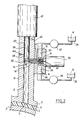
- FIGS. 1 to 4 are schematic sectional views of a device according to the invention, shown at different stages of the method according to the invention.
- the device shown in Figures 1 to 4 is used to penetrate a coating material inside a mold 2, 3 in which a part 1 has been previously formed.
- the mold consists of two elements 2, 3 defining between them a cavity.
- the thermosetting material of the part to be molded is placed in the mold cavity, the mold elements 2, 3 are pressed towards each other to put in place forms the part 1, then a known heat treatment is applied to the part 1 to make it harden at least partially and to make its surface 4 receptive to the coating to be applied.
- the coating is applied to the part 1 by causing the coating material to penetrate under high pressure (typically several hundred bars) inside the mold and without first removing the elements from mold 2, 3. This operation is carried out by implementing the present invention.
- the coating material used for example intended to form a primer or paint layer on a bodywork part, can be constituted by a single substance or by a mixture of several reactive components.
- the coating material C consists of a mixture of two components A, B.
- the device according to the invention comprises a chamber 6 which in the example shown, is constituted by a cylindrical channel of axis D formed in the upper mold element 2.
- the chamber 6 has a lower end 7 open towards the cavity formed inside the mold.
- the device according to the invention comprises injection means, indicated overall by the reference 13 in FIG. 1, for injecting the coating material into the chamber 6.
- injection means 13 comprise a cylindrical injection pipe 14 , transverse to the axis D of the chamber, having one end 16 open towards the interior of the chamber 6.
- the injection duct 14 is formed in a cylindrical part 17, the front part of which is installed in a sealed manner in an opening 18 formed in the wall 11 of the chamber 6. Behind the wall 11, this cylindrical part 17 has two diametrically opposite orifices 21, 22 which open into the injection pipe 14.
- each orifice 21, 22 communicates with a respective cavity 23, 24 formed in an element 26.
- the element 26 is mounted in leaktight manner around the rear part of the cylindrical part 17, and fixed by means s not shown on the wall 11 of the chamber 6.
- the injection means 13 further comprise pumping means comprising, for each component A, B of the coating material, a metering pump 27, 28 whose inlet is connected to a reservoir 29, 30 of said component, and whose outlet is connected to a respective cavity 23, 24 of the element 26 and to the corresponding orifice 21, 22.
- the metering pumps used 27, 28 are adapted to deliver each component A, B through the corresponding orifice 21, 22 under a first predetermined pressure PO.
- the pressure PO is for example of the order of 15 MPa (150 bars).
- the injection means 13 also comprise means for closing the injection pipe, comprising a needle 32 sliding in the injection pipe 14 and an actuator such as a hydraulic cylinder 33 connected to the needle 32.
- the needle 32 is mounted in conduit 14 with a substantially zero clearance so as to produce a seal by simple contact between the periphery of needle 32 and the wall of conduit 14.
- the needle 32 is movable in the injection pipe 14 between a closed position in which it closes both the end 16 of the pipe 14 open towards the chamber 6 and the two orifices 21, 22 ( Figures 1, 3 and 4), and a retraction position beyond the orifices 21, 22 relative to the open end 16 (FIG. 2).
- the jack 33 is chosen so that it can control the movement of the needle 32 in both directions between these two positions with a force F1 sufficient to overcome the pressure PO exerted at the orifices 21,22.
- a cylindrical piston 38 is slidably mounted parallel to the axis D in the chamber 6.
- the chamber 6 is arranged.
- the chamber 6 and the piston 38 are arranged so that the direction D of sliding of the piston is substantially vertical, with the end 7 of chamber 6 directed downwards.
- the piston 38 has an external cross section substantially identical to the internal cross section of the chamber 6. There is only a clearance of the order of 1 or 2 microns between the periphery 39 of the piston 38 and the wall 11 of chamber 6, which enables sealing by simple contact around the piston 38 movable in chamber 6.
- the piston 38 is movable in the chamber between a first position in which it closes the end 7 of the chamber 6 open towards the inside of the mold (lower position shown in Figures 1 and 4), and a second position beyond the injection duct 14 relative to the open end 7 of the chamber (upper retracted position shown in Figures 2 and 3).
- Actuating means such as a hydraulic cylinder 42 are connected to the piston 38 to control the movement of the piston 38 in both directions between these two positions.
- This second pressure P2 is greater than the first pressure PO under which the components A, B are injected into chamber 6.
- the second pressure P2 is for example of the order of 70 MPa (700 bars).
- the chamber 6 is extended by a section of coaxial cylindrical channel 43 having substantially the same interior cross-section as the chamber 6.
- a clearance slightly greater than that existing between the wall of the chamber 6 and the periphery 39 of the piston which allows applying a lubricant against the periphery 39 of the piston to promote its sliding in the channel composed of the section 43 and of the chamber 6.
- orifices 44, 45 are formed in the wall of the section of channel 43 to make circulate a lubricant on the periphery 39 of the piston 38, as schematically indicated by the arrows G, H in FIG. 1.
- the device When the part 1 has been shaped in the mold 1 and when the heat treatment ends, the device is in the state shown in FIG. 1.
- the piston 38 is in its lower position and the needle 32 in its closed position.
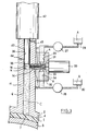
- the cylinder 42 is then controlled so that it displaces the piston 38 to its upper position, which creates a vacuum in the chamber 6.
- the cylinder 33 is controlled so that it displaces the needle 32 to its retraction position.
- the device is then in the state shown in FIG. 2.
- the material of the coating C is injected into the chamber 6 via the injection pipe 14 under the first pressure P0, as illustrated by the jet 50 shown at Figure 2.
- the two components A, B of the coating material are mixed during this injection step.
- the shutter needle 32 having been retracted, the metering pumps 27, 28 and the orifices 21, 22 form two opposite flows containing the two components A, B respectively under the first pressure P0.
- These two pressurized flows converge towards one another and collide against the current in an area located in the injection pipe 14, which mixes the two components A, B.
- the mixture thus formed is pushed by the pressure PO through the conduit 14 to the chamber 6.
- the jet of pressurized material 50 strikes the interior wall substantially perpendicularly of the chamber 6 opposite the injection pipe 14, which further improves the mixing of the two components A, B.
- the metering pumps 27, 28 measure the flow rates of the injected components A, B.
- the cylinder 33 is controlled to push the needle 32 to its closed position of the injection pipe 14. These volumes are chosen so that the level N of the coating material C in the chamber 6 at the end of step d injection remains lower than that of the injection pipe 14 (FIG. 3). This avoids any risk of reflux of the material C into the injection pipe 14 during the subsequent displacement of the piston 38.
- the actuator 42 is controlled so that it displaces the piston 42 towards its lower position.
- the force F2 applied by the jack 42 on the piston 38 is adjusted to correspond, inside the chamber 6, to the high pressure P2 desired to make the coating material penetrate into the mold.
- the device At the end of the downward movement of the piston 38, the device is in the state shown in FIG. 4.
- the material has penetrated into the mold and has come to form a coating 5 uniformly distributed on the surface 4 of the part 1.
- the method and the device according to the invention have the advantage that only the chamber 6 must withstand the very high pressure P2 (of the order of 700 bars) serving to force the coating material to penetrate between the part 1 and the mold 2, 3.
- the injection means 13 only have to withstand lower PO pressures (of the order of 150 bars), unlike the injection means used according to US-A-4 668 460. It is possible to thus using lighter and more economical elements to produce the injection means 13, or even increasing the penetration pressures without weighing down or complicating the injection means. In addition, the security conditions around the installation are improved.
- the method according to the invention therefore improves the productivity of the investment in equipment.
- the number of components of the coating material can be greater than two. There is then a corresponding number of orifices around the injection pipe for converging flows containing the different components.
- the device can also be used in the case of a single-component material, by providing a single orifice opening into the injection pipe.
Abstract
Description
La présente invention concerne un procédé pour faire pénétrer un matériau de revêtement sous haute pression à l'intérieur d'un moule, ainsi qu'un dispositif utilisable pour la mise en oeuvre de ce procédé.The present invention relates to a method for penetrating a coating material under high pressure inside a mold, as well as to a device which can be used for carrying out this method.
L'invention s'applique plus particulièrement à un revêtement d'apprêt ou de finition formé in situ sur une pièce moulée, c'est-à-dire à l'intérieur de son moule et avant d'écarter les éléments du moule et d'en extraire la pièce. Un tel procédé pour former un revêtement est décrit dans le US-A-4 668 460. Une pression élevée (plusieurs centaines de bars) est nécessaire pour faire pénétrer le matériau du revêtement entre le moule et la pièce et assurer une répartition régulière du revêtement à la surface de la pièce. Le matériau pénètre dans le moule par l'intermédiaire d'une chambre cylindrique dans laquelle coulisse une tige formant obturateur. Lorsque la tige est rétractée, la chambre communique avec un circuit d'injection comprenant des pompes délivrant le matériau à la haute pression désirée. Un inconvénient de cette technique est que, sauf à limiter les pressions utilisables, on doit donner à la chambre et au circuit d'injection une structure très robuste et donc coûteuse.The invention applies more particularly to a primer or finish coating formed in situ on a molded part, that is to say inside its mold and before removing the elements from the mold and d 'extract the part. Such a method for forming a coating is described in US-A-4 668 460. High pressure (several hundred bars) is necessary to make the coating material penetrate between the mold and the part and ensure an even distribution of the coating. on the surface of the room. The material enters the mold through a cylindrical chamber in which slides a rod forming a shutter. When the rod is retracted, the chamber communicates with an injection circuit comprising pumps delivering the material at the desired high pressure. A drawback of this technique is that, unless the usable pressures are limited, the chamber and the injection circuit must be given a very robust and therefore expensive structure.
Le US-A-4 668 460 indique que la technique ci-dessus est utilisable pour appliquer un matériau de revêtement constitué par un mélange de deux composants réactifs ou plus. Les composants préalablement mélangés sont injectés par l'intermédiaire du même circuit d'injection. Cependant, pour gagner du temps dans l'exécution du procédé et donc améliorer la productivité de l'équipement, il serait souhaitable de pouvoir réaliser le mélange des composants en même temps que l'injection.US-A-4 668 460 indicates that the above technique can be used to apply a coating material consisting of a mixture of two or more reactive components. The premixed components are injected via the same injection circuit. However, to save time in the execution of the process and therefore improve the productivity of the equipment, it would be desirable to be able to mix the components at the same time as the injection.
On connaît certes une autre technique dans laquelle une tête de mélange débouche directement vers l'intérieur du moule pour mélanger et injecter simultanément les composants. Mais la tête doit nécessairement comporter des orifices de petite section pour garantir un mélange intime des composants, ce qui limite les pressions utilisables en pratique. En outre, cette seconde technique nécessite de dédoubler le circuit d'injection délivrant la haute pression.Another technique is certainly known in which a mixing head opens directly into the interior of the mold for simultaneously mixing and injecting the components. However, the head must necessarily have orifices of small section to guarantee an intimate mixture of the components, which limits the pressures which can be used in practice. In addition, this second technique requires splitting the injection circuit delivering the high pressure.
Un but principal de la présente invention est de proposer un procédé et un dispositif qui remédie aux inconvénients ci-dessus et qui permette d'utiliser des pressions élevées pour faire pénétrer la matériau de revêtement dans le moule sans augmenter sensiblement la complexité ou le coût de l'équipement.A main object of the present invention is to provide a method and a device which overcomes the above drawbacks and which allows the use of high pressures to penetrate the coating material into the mold without significantly increasing the complexity or the cost of equipment.
Un autre but de l'invention est que le procédé soit applicable de façon simple dans le cas d'un matériau de revêtement obtenu à partir de plusieurs composants.Another object of the invention is that the method can be applied in a simple manner in the case of a coating material obtained from several components.
L'invention propose ainsi un procédé pour faire pénétrer un matériau de revêtement sous haute pression à l'intérieurd'un moule, dans lequel on utilise une chambre ayant une extrémité ouverte vers l'intérieur du moule et un conduit d'injection débouchant dans la chambre, caractérisé par la succession des étapes suivantes :
- - déplacement d'un piston mobile dans la chambre depuis une première position dans laquelle le piston obture l'extrémité ouverte de la chambre jusqu'à une seconde position au-delà du conduit d'injection relativement à l'extrémité ouverte de la chambre ;
- - injection du matériau de revêtement dans la chambre par l'intermédiaire du conduit d'injection sous une première pression ; et
- - déplacement du piston vers ladite première position en lui appliquant une force correspondant, à l'intérieur de la chambre, à une seconde pression supérieure à ladite première pression.
- - displacement of a movable piston in the chamber from a first position in which the piston closes the open end of the chamber to a second position beyond the injection pipe relative to the open end of the chamber;
- - injection of the coating material into the chamber via the injection pipe under a first pressure; and
- - displacement of the piston towards said first position by applying to it a force corresponding, inside the chamber, to a second pressure greater than said first pressure.
Ainsi, seuls la chambre et le piston nécessitent d'être conçus pour supporter la seconde pression appliquée pour faire pénétrer le matériau dans le moule. En amont de la chambre, les pressions exercées sont moins élevées et l'équipement correspondant peut donc être plus simple et plus économique. En outre, en réduisant le nombre de zones exposées à la plus haute pression, on améliore les conditions de sécurité au voisinage de l'installation.Thus, only the chamber and the piston need to be designed to withstand the second pressure applied to make the material penetrate the mold. Upstream of the chamber, the pressures exerted are lower and the corresponding equipment can therefore be simpler and more economical. In addition, by reducing the number of zones exposed to the highest pressure, the safety conditions in the vicinity of the installation are improved.
Dans une version préférée du procédé, dans laquelle le matériau de revêtement est constitué par un mélange d'au moins deux composants, on effectue le mélange des deux composants pendant l'étape d'injection en faisant converger plusieurs flux contenant respectivement les composants sous ladite première pression.In a preferred version of the method, in which the coating material consists of a mixture of at least two components, the two components are mixed during the injection step by converging several streams containing the components respectively under said first press.
Le mélange et l'injection simultanés des composants permet d'exécuter le procédé en un temps relativement court. On peut alors régler la première pression pour obtenir un mélange homogène des composants réactifs dans des conditions optimales, tandis que la seconde pression est déterminée pour obtenir la meilleure répartition du matériau dans le moule après le mélange.The simultaneous mixing and injection of the components allows the process to be carried out in a relatively short time. The first pressure can then be adjusted to obtain a homogeneous mixture of the reactive components under optimal conditions, while the second pressure is determined to obtain the best distribution of the material in the mold after mixing.
Le second aspect de l'invention vise un dispositif pour faire pénétrer un matériau de revêtement sous haute pression à l'intérieur d'un moule, comprenant une chambre ayant une extrémité ouverte vers l'intérieur du moule et des moyens d'injection pour injecter le matériau de revêtement dans la chambre, ces moyens d'injection incluant un conduit d'injection débouchant dans la chambre, caractérisé en ce qu'il comprend en outre un piston mobile dans la chambre entre une première position dans laquelle le piston obture l'extrémité ouverte de la chambre et une seconde position au-delà du conduit d'injection relativement à l'extrémité ouverte de la chambre, en ce que les moyens d'injection sont adaptés pour injecter le matériau de revêtement dans la chambre sous une première pression, et en ce que des moyens d'actionnement du piston sont prévus pour déplacer le piston dans le sens allant de ladite seconde position à ladite première position avec une force correspondant, à l'intérieur de la chambre, à une seconde pression supérieure à ladite première pression.The second aspect of the invention relates to a device for penetrating a coating material under high pressure inside a mold, comprising a chamber having one end open towards the inside of the mold and injection means for injecting the coating material in the chamber, these injection means including an injection conduit opening into the chamber, characterized in that it further comprises a piston movable in the chamber between a first position in which the piston closes the open end of the chamber and a second position beyond the injection pipe relative to the open end of the chamber, in that the injection means are adapted to inject the coating material into the chamber under a first pressure , and in that means for actuating the piston are provided for moving the piston in the direction going from said second position to said first position with a corresponding force. ndant, inside the chamber, at a second pressure on prior to said first pressure.
Ce dispositif est conçu pour la mise en oeuvre du procédé exposé ci-dessus.This device is designed for implementing the method described above.
D'autres particularités et avantages de la présente invention apparaîtront dans la description ci-après d'un exemple de réalisation préféré et non limitatif, lue conjointement aux dessins annexés, dans lesquels :Other features and advantages of the present invention will appear in the description below of a preferred and nonlimiting exemplary embodiment, read in conjunction with the appended drawings, in which:
- les figures 1 à 4 sont des vues schématiques en coupe d'un dispositif selon l'invention, représenté à différents stades du procédé selon l'invention.- Figures 1 to 4 are schematic sectional views of a device according to the invention, shown at different stages of the method according to the invention.
Le dispositif représenté aux figures 1 à 4 sert à faire pénétrer un matériau de revêtement à l'intérieur d'un moule 2, 3 dans lequel une pièce 1 a préalablement été formée. Le moule se compose de deux éléments 2, 3 définissant entre eux une cavité. Pour réaliser la pièce 1 et la préparer à l'application du revêtement, on place la matière thermodurcissable de la pièce à mouler dans la cavité du moule, on appuie les éléments de moule 2, 3 l'un vers l'autre pour mettre en forme la pièce 1, puis on applique un traitement thermique connu à la pièce 1 pour la faire durcir au moins partiellement et pour rendre sa surface 4 réceptive au revêtement à appliquer.The device shown in Figures 1 to 4 is used to penetrate a coating material inside a
Comme exposé dans le US-A-4 668 460, le revêtement est appliqué sur la pièce 1 en faisant pénétrer le matériau du revêtement sous haute pression (typiquement plusieurs centaines de bars) à l'intérieur du moule et sans écarter préalablement les éléments de moule 2, 3. Cette opération est exécutée en mettant en oeuvre la présente invention.As explained in US-A-4 668 460, the coating is applied to the
Le matériau de revêtement utilisé, par exemple destiné à former une couche d'apprêt ou de peinture sur une pièce de carrosserie, peut être constitué par une substance unique ou par un mélange de plusieurs composants réactifs. Dans l'exemple préféré décrit ci-après, le matériau de revêtement C est constitué par un mélange de deux composants A, B.The coating material used, for example intended to form a primer or paint layer on a bodywork part, can be constituted by a single substance or by a mixture of several reactive components. In the preferred example described below, the coating material C consists of a mixture of two components A, B.
Le dispositif selon l'invention comprend une chambre 6 qui dans l'exemple représenté, est constituée par un canal cylindrique d'axe D formé dans l'élément de moule supérieur 2. La chambre 6 a une extrémité inférieure 7 ouverte vers la cavité formée à l'intérieur du moule.The device according to the invention comprises a
Le dispositif selon l'invention comprend des moyens d'injection, indiqués globalement par la référence numérique 13 à la figure 1, pour injecter le matériau du revêtement dans la chambre 6. Ces moyens d'injection 13 comprennent un conduit d'injection cylindrique 14, transversal à l'axe D de la chambre, ayant une extrémité 16 ouverte vers l'intérieur de la chambre 6. Le conduit d'injection 14 est formé dans une pièce cylindrique 17 dont la partie avant est installée de manière étanche dans une ouverture 18 ménagée dans la paroi 11 de la chambre 6. En arrière de la paroi 11, cette pièce cylindrique 17 comporte deux orifices 21, 22 diamétralement opposés qui débouchent dans le conduit d'injection 14. Du côté opposé au conduit d'injection 14, chaque orifice 21, 22 communique avec une cavité respective 23, 24 formée dans un élément 26. L'élément 26 est monté de manière étanche autour de la partie arrière de la pièce cylindrique 17, et fixé par des moyens non représentés à la paroi 11 de la chambre 6.The device according to the invention comprises injection means, indicated overall by the
Les moyens d'injection 13 comprennent en outre des moyens de pompage comportant, pour chaque composantA, B du matériau de revêtement, une pompe doseuse 27, 28 dont l'entrée est reliée à un réservoir 29,30 dudit composant, et dont la sortie est reliée à une cavité respective 23, 24 de l'élément 26 et à l'orifice correspondant 21, 22. Les pompes doseuses utilisées 27, 28 sont adaptées pour délivrer chaque composant A, B à travers l'orifice correspondant 21, 22 sous une première pression prédéterminée PO. La pression PO est par exemple de l'ordre de 15 MPa (150 bars).The injection means 13 further comprise pumping means comprising, for each component A, B of the coating material, a
Les moyens d'injection 13 comprennent également des moyens d'obturation du conduit d'injection, comportant une aiguille 32 coulissant dans le conduit d'injection 14 et un actionneur tel qu'un vérin hydraulique 33 relié à l'aiguille 32. L'aiguille 32 est montée dans le conduit 14 avec un jeu sensiblement nul de façon à réaliser une étanchéité par simple contact entre la périphérie de l'aiguille 32 et la paroi du conduit 14.The injection means 13 also comprise means for closing the injection pipe, comprising a
L'aiguille 32 est mobile dans le conduit d'injection 14 entre une position d'obturation dans laquelle elle obture à la fois l'extrémité 16 du conduit 14 ouverte vers la chambre 6 et les deux orifices 21, 22 (figures 1, 3 et 4), et une position de rétractation au-delà des orifices 21, 22 relativement à l'extrémité ouverte 16 (figure 2). Le vérin 33 est choisi de façon qu'il puisse commander le déplacement de l'aiguille 32 dans les deux sens entre ces deux positions avec une force F1 suffisante pour vaincre la pression PO s'exerçant au niveau des orifices 21,22. Le vérin 33 peut par exemple actionner l'aiguille 32 avec une force F1 = P1 x S1 correspondant, à l'intérieur du conduit d'injection 14, à une pression P1 de l'ordre de 20 MPa (200 bars) supérieure à la pression PO, S1 désignant l'aire de la section transversale intérieure du conduit 14.The
Un piston cylindrique 38 est monté coulissant parallèlement à l'axe D dans la chambre 6. On dispose la chambre 6. On dispose la chambre 6 et le piston 38 de façon que la direction D de coulissement du piston soit sensiblement verticale, avec l'extrémité 7 de la chambre 6 dirigée vers le bas. Le piston 38 a une section transversale extérieure sensiblement identique à la section transversale intérieure de la chambre 6. Il n'y a qu'un jeu de l'ordre de 1 ou 2 microns entre la périphérie 39 du piston 38 et la paroi 11 de la chambre 6, ce qui permet de réaliser une étanchéité par simple contact autour du piston 38 mobile dans la chambre 6.A
Le piston 38 est mobile dans la chambre entre une première position dans laquelle il obture l'extrémité 7 de la chambre 6 ouverte vers l'intérieur du moule (position inférieure représentée aux figures 1 et 4), et une seconde position au-delà du conduit d'injection 14 relativement à l'extrémité ouverte 7 de la chambre (position supérieure rétractée représentée aux figures 2 et 3).The
Des moyens d'actionnement tels qu'un vérin hydraulique 42 sont reliés au piston 38 pour commander le déplacement du piston 38 dans les deux sens entre ces deux positions. Dans le sens allant de la position supérieure à la position inférieure, le vérin 42 peut pousser le piston 38 avec une force F2 = P2 x S2 correspondant à l'intérieur de la chambre 6, à une seconde pression prédéterminée P2 égale à la haute pression désirée pourfaire pénétrer le matériau de revêtement à l'intérieur du moule, S2 désignant l'aire de la section transversale intérieure de la chambre 6. Cette seconde pression P2 est supérieure à la première pression PO sous laquelle les composants A, B sont injectés dans la chambre 6. La seconde pression P2 est par exemple de l'ordre de 70 MPa (700 bars).Actuating means such as a
Au-dessus du conduit d'injection 14, c'est-à-dire au-delà de ce conduit relativement à l'extrémité ouverte 7 de la chambre, la chambre 6 se prolonge par un tronçon de canal cylindrique coaxial 43 ayant sensiblement la même section transversale intérieure que la chambre 6. Il existe toutefois entre la paroi du tronçon de canal 43 et la périphérie 39 du piston un jeu légèrement supérieur à celui existant entre la paroi de la chambre 6 et la périphérie 39 du piston, ce qui permet d'appliquer un lubrifiant contre la périphérie 39 du piston pour favoriser son coul issement dans le canal composé du tronçon 43 et de la chambre 6. A cette fin, des orifices 44, 45 sont ménagés dans la paroi du tronçon de canal 43 pour faire circuler un lubrifiant sur la périphérie 39 du piston 38, comme l'indiquent schématiquement les flèches G, H à la figure 1.Above the
On va maintenant décrire le fonctionnement du dispositif ci-dessus, ce qui fera apparaître les particularités du procédé selon l'invention.We will now describe the operation of the above device, which will reveal the features of the method according to the invention.
Au moment où la pièce 1 a été mise en forme dans le moule 1 et où le traitement thermique se termine, le dispositif est dans l'état représenté à la figure 1. Le piston 38 est dans sa position inférieure et l'aiguille 32 dans sa position d'obturation.When the
On commande alors le vérin 42 pour qu'il déplace le piston 38 jusqu'à sa position supérieure, ce qui réalise le vide dans la chambre 6. Puis, on commande le vérin 33 pour qu'il déplace l'aiguille 32 jusqu'à sa position de rétractation. Le dispositif est alors dans l'état représenté à la figure 2. Le matériau du revêtement C est injecté dans la chambre 6 par l'intermédiaire du conduit d'injection 14 sous la première pression P0, comme l'illustre le jet 50 représenté à la figure 2.The
Le mélange des deux composants A, B du matériau de revêtement a lieu pendant cette étape d'injection. L'aiguille d'obturation 32 ayant été rétractée, les pompes doseuses 27, 28 et les orifices 21, 22 forment deux flux opposés contenant respectivement les deux composants A, B sous la première pression P0. Ces deux flux sous pression convergent l'un vers l'autre et se heurtent à contre-courant dans une zone située dans le conduit d'injection 14, ce qui mélange les deux composants A, B. Le mélange ainsi formé est poussé par la pression PO à travers le conduit 14 jusqu'à la chambre 6. Comme le conduit d'injection 14 est transversal à la direction D de coulissement du piston 38 dans la chambre 6, le jet de matériau sous pression 50 heurte sensiblement perpendiculairement la paroi intérieure de la chambre 6 en face du conduit d'injection 14, ce qui améliore encore le mélange des deux composants A, B.The two components A, B of the coating material are mixed during this injection step. The
Pendant l'étape d'injection du matériau de revêtement dans la chambre 6, les pompes doseuses 27, 28 mesurent les débits des composants injectés A, B. Lorsque les volumes désirés des deux composants A, B, ont été injectés, le vérin 33 est commandé pour pousser l'aiguille 32 jusqu'à sa position d'obturation du conduit d'injection 14. Ces volumes sont choisis de façon que le niveau N du matériau de revêtement C dans la chambre 6 à la fin de l'étape d'injection reste inférieur celui du conduit d'injection 14 (figure 3). On évite ainsi tout risque de reflux du matériau C dans le conduit d'injection 14 lors du déplacement ultérieur du piston 38.During the step of injecting the coating material into the
Le conduit 14 ayant été obturé, on commande le vérin 42 pour qu'il déplace le piston 42 vers sa position inférieure. La force F2 appliquée par le vérin 42 sur le piston 38 est réglée pour correspondre, à l'intérieur de la chambre 6, à la haute pression P2 désirée pour faire pénétrer le matériau de revêtement dans le moule.The
A la fin du déplacement vers le bas du piston 38, le dispositif est dans l'état représenté à la figure 4. Le matériau a pénétré dans le moule et est venu former un revêtement 5 uniformément réparti à la surface 4 de la pièce 1.At the end of the downward movement of the
Le procédé et le dispositif selon l'invention présentent l'avantage que seule la chambre 6 doit supporter la très haute pression P2 (de l'ordre de 700 bars) servant à faire pénétrer en force le matériau du revêtement entre la pièce 1 et le moule 2, 3. Les moyens d'injection 13 n'ont à supporter que des pressions PO moindres (de l'ordre de 150 bars), contrairement aux moyens d'injection utilisés selon le US-A-4 668 460. On peut ainsi utiliser des éléments plus légers et plus économiques pour réaliser les moyens d'injection 13, ou encore augmenter les pressions de pénétration sans alourdir ou compliquer les moyens d'injection. En outre, les conditions de sécurité autour de l'installation sont améliorées.The method and the device according to the invention have the advantage that only the
Le mélange des composants A, B ayant lieu pendant leur injection dans la chambre 6, on réalise un gain de temps par rapport aux procédés connus dans lesquels une étape de mélange doit être effectuée au préalable, sans augmenter sensiblement le coût de l'équipement nécessaire. Le procédé selon l'invention améliore donc la productivité de l'investissement en équipement.The mixing of the components A, B taking place during their injection into the
Bien qu'on ait décrit l'invention en référence à un exemple de réalisation préféré, on comprendra que cet exemple n'est pas limitatif et que diverses modifications peuvent lui être apportées sans sortir du cadre de l'invention.Although the invention has been described with reference to a preferred embodiment, it will be understood that this example is not limiting and that various modifications can be made to it without departing from the scope of the invention.
Ainsi, le nombre de composants du matériau de revêtement peut être supérieur à deux. On dispose alors un nombre correspondant d'orifices autour du conduit d'injection pour faire converger des flux contenant les différents composants. Le dispositif est également utilisable dans le cas d'un matériau mono- composant, en prévoyant un seul orifice débouchant dans le conduit d'injection.Thus, the number of components of the coating material can be greater than two. There is then a corresponding number of orifices around the injection pipe for converging flows containing the different components. The device can also be used in the case of a single-component material, by providing a single orifice opening into the injection pipe.
Claims (16)
Applications Claiming Priority (2)
| Application Number | Priority Date | Filing Date | Title |
|---|---|---|---|
| FR9202903A FR2688440B1 (en) | 1992-03-11 | 1992-03-11 | METHOD AND DEVICE FOR PENETRATING A HIGH-PRESSURE COATING MATERIAL WITHIN A MOLD. |
| FR9202903 | 1992-03-11 |
Publications (2)
| Publication Number | Publication Date |
|---|---|
| EP0560643A1 true EP0560643A1 (en) | 1993-09-15 |
| EP0560643B1 EP0560643B1 (en) | 1996-02-07 |
Family
ID=9427582
Family Applications (1)
| Application Number | Title | Priority Date | Filing Date |
|---|---|---|---|
| EP93400403A Expired - Lifetime EP0560643B1 (en) | 1992-03-11 | 1993-02-18 | Process and apparatus for high pressure in-mould coating |
Country Status (7)
| Country | Link |
|---|---|
| US (1) | US5435710A (en) |
| EP (1) | EP0560643B1 (en) |
| JP (1) | JPH0615696A (en) |
| CA (1) | CA2091433A1 (en) |
| DE (1) | DE69301474T2 (en) |
| ES (1) | ES2085731T3 (en) |
| FR (1) | FR2688440B1 (en) |
Cited By (2)
| Publication number | Priority date | Publication date | Assignee | Title |
|---|---|---|---|---|
| WO1998023431A1 (en) * | 1996-11-27 | 1998-06-04 | Petri Ag | Method and device for producing a multilayer plastic element |
| EP2591922A1 (en) | 2002-04-03 | 2013-05-15 | De La Rue International Limited | Optically variable security device and method |
Families Citing this family (6)
| Publication number | Priority date | Publication date | Assignee | Title |
|---|---|---|---|---|
| DE29521023U1 (en) * | 1995-05-08 | 1996-08-01 | Krauss Maffei Ag | Reaction casting machine |
| BR9912639A (en) * | 1998-07-31 | 2001-05-02 | Lomold Internat Ltd | Molding apparatus and molding method |
| DE19948278A1 (en) * | 1999-10-06 | 2001-04-19 | Battenfeld Gmbh | Method and device for multi-component injection molding of plastic molded parts |
| US6997690B2 (en) * | 2001-08-08 | 2006-02-14 | Masco Corporation | Flushless mold valve assembly |
| DE102005049640A1 (en) * | 2005-10-18 | 2007-04-19 | Bayer Materialscience Ag | Mold for the production of plastic moldings by reaction injection molding |
| IT202000009199A1 (en) * | 2020-04-28 | 2021-10-28 | Faf Company Srls | IMPROVED INJECTION GROUP |
Citations (6)
| Publication number | Priority date | Publication date | Assignee | Title |
|---|---|---|---|---|
| FR1206296A (en) * | 1958-07-09 | 1960-02-09 | New injection process for plastic material or made such | |
| US4076788A (en) * | 1976-12-02 | 1978-02-28 | General Motors Corporation | Mold coating of freshly molded articles |
| EP0113222A2 (en) * | 1983-01-06 | 1984-07-11 | Ford Motor Company Limited | Back flush injection nozzle |
| EP0197496A2 (en) * | 1985-04-02 | 1986-10-15 | The Sherwin-Williams Company | Molding with in-mold coating |
| US4720364A (en) * | 1985-04-15 | 1988-01-19 | Trans Plastics, Inc. | Method for injection molding fiber-reinforced thermoset plastic articles |
| US5011399A (en) * | 1989-11-02 | 1991-04-30 | Bm Corp. | High capacity injection molding apparatus |
Family Cites Families (1)
| Publication number | Priority date | Publication date | Assignee | Title |
|---|---|---|---|---|
| JPS59199226A (en) * | 1983-04-28 | 1984-11-12 | Bridgestone Corp | In-mold coating apparatus of sheet molding compound molded article |
-
1992
- 1992-03-11 FR FR9202903A patent/FR2688440B1/en not_active Expired - Fee Related
-
1993
- 1993-02-18 DE DE69301474T patent/DE69301474T2/en not_active Expired - Fee Related
- 1993-02-18 ES ES93400403T patent/ES2085731T3/en not_active Expired - Lifetime
- 1993-02-18 EP EP93400403A patent/EP0560643B1/en not_active Expired - Lifetime
- 1993-03-10 CA CA002091433A patent/CA2091433A1/en not_active Abandoned
- 1993-03-11 US US08/029,734 patent/US5435710A/en not_active Expired - Lifetime
- 1993-03-11 JP JP5050721A patent/JPH0615696A/en active Pending
Patent Citations (6)
| Publication number | Priority date | Publication date | Assignee | Title |
|---|---|---|---|---|
| FR1206296A (en) * | 1958-07-09 | 1960-02-09 | New injection process for plastic material or made such | |
| US4076788A (en) * | 1976-12-02 | 1978-02-28 | General Motors Corporation | Mold coating of freshly molded articles |
| EP0113222A2 (en) * | 1983-01-06 | 1984-07-11 | Ford Motor Company Limited | Back flush injection nozzle |
| EP0197496A2 (en) * | 1985-04-02 | 1986-10-15 | The Sherwin-Williams Company | Molding with in-mold coating |
| US4720364A (en) * | 1985-04-15 | 1988-01-19 | Trans Plastics, Inc. | Method for injection molding fiber-reinforced thermoset plastic articles |
| US5011399A (en) * | 1989-11-02 | 1991-04-30 | Bm Corp. | High capacity injection molding apparatus |
Non-Patent Citations (1)
| Title |
|---|
| PATENT ABSTRACTS OF JAPAN vol. 9, no. 67 (M-366)(1790) 27 Mars 1985 & JP-A-59 199 226 ( BRIGESTONE K.K. ) 12 Novembre 1984 * |
Cited By (2)
| Publication number | Priority date | Publication date | Assignee | Title |
|---|---|---|---|---|
| WO1998023431A1 (en) * | 1996-11-27 | 1998-06-04 | Petri Ag | Method and device for producing a multilayer plastic element |
| EP2591922A1 (en) | 2002-04-03 | 2013-05-15 | De La Rue International Limited | Optically variable security device and method |
Also Published As
| Publication number | Publication date |
|---|---|
| EP0560643B1 (en) | 1996-02-07 |
| DE69301474T2 (en) | 1996-07-11 |
| CA2091433A1 (en) | 1993-09-12 |
| FR2688440A1 (en) | 1993-09-17 |
| FR2688440B1 (en) | 1994-05-13 |
| US5435710A (en) | 1995-07-25 |
| DE69301474D1 (en) | 1996-03-21 |
| ES2085731T3 (en) | 1996-06-01 |
| JPH0615696A (en) | 1994-01-25 |
Similar Documents
| Publication | Publication Date | Title |
|---|---|---|
| EP0560643B1 (en) | Process and apparatus for high pressure in-mould coating | |
| FR2466292A1 (en) | EVENT DEVICE FOR INJECTION MOLD | |
| EP3227094B1 (en) | Moulding device and process for the manufacture of composite components from liquid polymer resin by high-pressure injection | |
| EP1066148B1 (en) | Method for producing a motor vehicle body part by plastic material injection, method for sequential injection of plastic material, mould for implementing said methods, and resulting plastic part | |
| EP1883478B1 (en) | Nozzle comprising a swirl chamber | |
| FR2519266A1 (en) | DEVICE FOR MIXING AND DOSE DISTRIBUTION OF A PRODUCT AND APPLICATION FOR THE DELIVERY OF GLUES, IN PARTICULAR BASED ON EPOXY RESIN | |
| EP3797875B1 (en) | Method for automatically applying a viscous product to a rivet head | |
| FR2497686A1 (en) | DEVICE FOR MIXING CHEMICAL COMPONENTS, PARTICULARLY REACTIVE, PROVIDED WITH MOBILE INJECTORS | |
| EP1440780A1 (en) | Needle valve for filling a mould with a liquid organic material and process for moulding an optical element using such a valve | |
| EP0587483B1 (en) | Injection press and use thereof | |
| FR2652538A1 (en) | PRESSURE GAS INJECTOR IN A MOLD FOR MANUFACTURING A PLASTIC MATERIAL, MOLD AND MOLDING METHOD USING SUCH AN INJECTOR AND A PLASTIC MATERIAL OBTAINED. | |
| FR2558103A1 (en) | METHOD FOR COLD INJECTION MOLDING OF THERMOSETTING COMPOSITE MATERIALS AND DEVICE FOR IMPLEMENTING THE SAME | |
| WO2020043982A1 (en) | Resin injection modulator, resin injection circuit and associated methods | |
| FR2803240A1 (en) | METHOD FOR ASSEMBLING TWO SHEETS | |
| WO2019180093A1 (en) | Ceramic additive manufacturing method by liquid means, and device for implementing said method | |
| FR2615037A1 (en) | PROCESS AND MOLD FOR ENCAPSULATION OF A SEMICONDUCTOR DEVICE BY RESIN INJECTION | |
| EP3227075B1 (en) | Moulding device and method for the manufacture of composite components using liquid polymer resin | |
| FR2729886A1 (en) | In mould paint coating of plastic parts for car interior bodywork | |
| EP3959063B1 (en) | Extrusion head for additive manufacture, system and method for additive manufacture | |
| FR2616085A1 (en) | Device for delivering a pressurised mixture of at least two fluids | |
| CH370004A (en) | Plant for the production of plastic containers | |
| EP0153539B1 (en) | Process and device for coating the faces of a propellant grain | |
| FR2476824A1 (en) | Mud gun for plugging tap-holes in metallurgical furnaces - where bore of gun is coated with hard chromium to minimise abrasive wear | |
| JPH0880549A (en) | Prepla-type injection molding machine | |
| EP4134167A1 (en) | Lancehead |
Legal Events
| Date | Code | Title | Description |
|---|---|---|---|
| PUAI | Public reference made under article 153(3) epc to a published international application that has entered the european phase |
Free format text: ORIGINAL CODE: 0009012 |
|
| AK | Designated contracting states |
Kind code of ref document: A1 Designated state(s): DE ES GB IT |
|
| 17P | Request for examination filed |
Effective date: 19940117 |
|
| 17Q | First examination report despatched |
Effective date: 19950713 |
|
| GRAA | (expected) grant |
Free format text: ORIGINAL CODE: 0009210 |
|
| AK | Designated contracting states |
Kind code of ref document: B1 Designated state(s): DE ES GB IT |
|
| ITF | It: translation for a ep patent filed |
Owner name: JACOBACCI & PERANI S.P.A. |
|
| GBT | Gb: translation of ep patent filed (gb section 77(6)(a)/1977) |
Effective date: 19960209 |
|
| REF | Corresponds to: |
Ref document number: 69301474 Country of ref document: DE Date of ref document: 19960321 |
|
| REG | Reference to a national code |
Ref country code: ES Ref legal event code: FG2A Ref document number: 2085731 Country of ref document: ES Kind code of ref document: T3 |
|
| PLBE | No opposition filed within time limit |
Free format text: ORIGINAL CODE: 0009261 |
|
| STAA | Information on the status of an ep patent application or granted ep patent |
Free format text: STATUS: NO OPPOSITION FILED WITHIN TIME LIMIT |
|
| 26N | No opposition filed | ||
| REG | Reference to a national code |
Ref country code: GB Ref legal event code: IF02 |
|
| PGFP | Annual fee paid to national office [announced via postgrant information from national office to epo] |
Ref country code: ES Payment date: 20090211 Year of fee payment: 17 |
|
| PGFP | Annual fee paid to national office [announced via postgrant information from national office to epo] |
Ref country code: DE Payment date: 20090227 Year of fee payment: 17 |
|
| PGFP | Annual fee paid to national office [announced via postgrant information from national office to epo] |
Ref country code: GB Payment date: 20090128 Year of fee payment: 17 |
|
| PGFP | Annual fee paid to national office [announced via postgrant information from national office to epo] |
Ref country code: IT Payment date: 20090210 Year of fee payment: 17 |
|
| GBPC | Gb: european patent ceased through non-payment of renewal fee |
Effective date: 20100218 |
|
| PG25 | Lapsed in a contracting state [announced via postgrant information from national office to epo] |
Ref country code: DE Free format text: LAPSE BECAUSE OF NON-PAYMENT OF DUE FEES Effective date: 20100901 |
|
| REG | Reference to a national code |
Ref country code: ES Ref legal event code: FD2A Effective date: 20110324 |
|
| PG25 | Lapsed in a contracting state [announced via postgrant information from national office to epo] |
Ref country code: GB Free format text: LAPSE BECAUSE OF NON-PAYMENT OF DUE FEES Effective date: 20100218 Ref country code: IT Free format text: LAPSE BECAUSE OF NON-PAYMENT OF DUE FEES Effective date: 20100218 |
|
| PG25 | Lapsed in a contracting state [announced via postgrant information from national office to epo] |
Ref country code: ES Free format text: LAPSE BECAUSE OF NON-PAYMENT OF DUE FEES Effective date: 20110310 |
|
| PG25 | Lapsed in a contracting state [announced via postgrant information from national office to epo] |
Ref country code: ES Free format text: LAPSE BECAUSE OF NON-PAYMENT OF DUE FEES Effective date: 20100219 |