EP0560676A1 - Cross-flow heat-exchanger - Google Patents
Cross-flow heat-exchanger Download PDFInfo
- Publication number
- EP0560676A1 EP0560676A1 EP93400612A EP93400612A EP0560676A1 EP 0560676 A1 EP0560676 A1 EP 0560676A1 EP 93400612 A EP93400612 A EP 93400612A EP 93400612 A EP93400612 A EP 93400612A EP 0560676 A1 EP0560676 A1 EP 0560676A1
- Authority
- EP
- European Patent Office
- Prior art keywords
- flat plate
- corrugations
- plate
- exchanger according
- flaps
- Prior art date
- Legal status (The legal status is an assumption and is not a legal conclusion. Google has not performed a legal analysis and makes no representation as to the accuracy of the status listed.)
- Withdrawn
Links
Images
Classifications
-
- F—MECHANICAL ENGINEERING; LIGHTING; HEATING; WEAPONS; BLASTING
- F28—HEAT EXCHANGE IN GENERAL
- F28F—DETAILS OF HEAT-EXCHANGE AND HEAT-TRANSFER APPARATUS, OF GENERAL APPLICATION
- F28F3/00—Plate-like or laminated elements; Assemblies of plate-like or laminated elements
- F28F3/02—Elements or assemblies thereof with means for increasing heat-transfer area, e.g. with fins, with recesses, with corrugations
- F28F3/04—Elements or assemblies thereof with means for increasing heat-transfer area, e.g. with fins, with recesses, with corrugations the means being integral with the element
- F28F3/042—Elements or assemblies thereof with means for increasing heat-transfer area, e.g. with fins, with recesses, with corrugations the means being integral with the element in the form of local deformations of the element
- F28F3/046—Elements or assemblies thereof with means for increasing heat-transfer area, e.g. with fins, with recesses, with corrugations the means being integral with the element in the form of local deformations of the element the deformations being linear, e.g. corrugations
-
- F—MECHANICAL ENGINEERING; LIGHTING; HEATING; WEAPONS; BLASTING
- F28—HEAT EXCHANGE IN GENERAL
- F28D—HEAT-EXCHANGE APPARATUS, NOT PROVIDED FOR IN ANOTHER SUBCLASS, IN WHICH THE HEAT-EXCHANGE MEDIA DO NOT COME INTO DIRECT CONTACT
- F28D9/00—Heat-exchange apparatus having stationary plate-like or laminated conduit assemblies for both heat-exchange media, the media being in contact with different sides of a conduit wall
- F28D9/0031—Heat-exchange apparatus having stationary plate-like or laminated conduit assemblies for both heat-exchange media, the media being in contact with different sides of a conduit wall the conduits for one heat-exchange medium being formed by paired plates touching each other
- F28D9/0037—Heat-exchange apparatus having stationary plate-like or laminated conduit assemblies for both heat-exchange media, the media being in contact with different sides of a conduit wall the conduits for one heat-exchange medium being formed by paired plates touching each other the conduits for the other heat-exchange medium also being formed by paired plates touching each other
Definitions
- the present invention relates to a heat exchanger of the cross-flow type, comprising a stack of identical elements held between posts and each consisting of a corrugated plate with corrugations parallel to each other, thus defining channels, and a flat plate. in contact on one side with the bottoms of the above corrugations, and on the other side with the tops of the corrugations of the next corrugated plate, these latter corrugations, also parallel to each other, extending in a direction perpendicular to that of the corrugations from the previous corrugated sheet.
- the corrugated sheets and the flat sheets can for example be made of thin sheets of steel or aluminum. It is understood that the corrugations form between them channels open at their ends but which are closed on one side and on the other by the flat plates, the latter thus preventing the hot and cold flows from mixing. However, a risk of communication between these two flows remains at the ends of these channels. Indeed, in the case, for example, of a flat plate edge extending obliquely, that is to say which is not perfectly parallel to the undulations of the corresponding element, one of the fluids can pass from the channel adjacent to this bias edge in the ends of the channels of the neighboring element, which allows communication between the cold and hot fluids.
- an exchanger according to the invention of the general type defined at the start, is characterized in that each flat plate has two lines of two opposite ends folding parallel to the direction of the corrugations of the corresponding corrugated plate, so as to constitute at these two ends a flap covering one or more of the extreme undulations of the latter plate, and in that the flaps of the flat plate of each element are fixed along their entire length, with no solution of continuity, over the extreme zones of corresponding width of the flat plate of the neighboring element.
- flaps will prevent any leakage between an end channel of the flat plate of an element of the stack, and the ends of the channels of the neighboring element. They will also help to ensure excellent rigidity and a very beautiful appearance to the entire stack.
- the two aforementioned folds are each performed at 90 °, so that said flaps extend parallel to the corresponding flat plate.
- Fixing the flaps of the flat plate of an element on the extreme zones of corresponding width of the flat plate of the neighboring element can be done by any suitable means, preferably by gluing, but we can also consider a type of puttying at high temperature, or welding.
- a heat exchanger according to the invention can theoretically be constituted by a stack of any number of elements A, B, C ... In FIG. 1, only three have been shown, which is sufficient to explain the invention.
- Each of these elements consists of a corrugated plate 1 with corrugations parallel to each other, and a flat plate 2 in contact with the bottoms f of these corrugations.
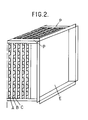
- the vertices s of these same corrugations come into contact with the flat plate 2 of the neighboring element when all the elements of the stack are clamped between end plates E, to form the compact block visible in FIG. 2.
- the corrugations of the latter have a trapezoidal profile, that is to say that the bottoms f and the vertices s are flat and constitute the small base of each trapezoid.
- the ends of the flat plates 2 whose edges are parallel to the corrugations of the corresponding plate 1 are folded inwards, twice at right angles, along the fold lines 3 and 4, so as to constitute flaps 5.
- the distance between the lines 3 and 4 is only very slightly greater than the height of the above-mentioned trapezoids, so that the flaps 5 remain parallel to the plane of the flat plates 2.
- the flaps 5 are wide enough to cover one or more undulations.
- the entire surface of the flaps 5 is coated with an appropriate glue, or any other fixing means, which will fix these flaps 5 to the areas without a solution of continuity. corresponding extremes 6 of the back of the flat plate 2 of the neighboring element.
- the dimensions of the corrugated sheets 1, seen in plan are chosen so as to be slightly smaller than those of the flat sheets 2.
Abstract
Description
La présente invention concerne un échangeur de chaleur du type à courants croisés, comportant un empilage d'éléments identiques maintenus entre des poteaux et constitués chacun d'une plaque ondulée à ondulations parallèles entre elles, définissant ainsi des canaux, et d'une plaque plane en contact d'un côté avec les fonds des ondulations précitées, et de l'autre côté avec les sommets des ondulations de la plaque ondulée suivante, ces dernières ondulations, également parallèles entre elles, s'étendant dans une direction perpendiculaire à celle des ondulations de la plaque ondulée précédente.The present invention relates to a heat exchanger of the cross-flow type, comprising a stack of identical elements held between posts and each consisting of a corrugated plate with corrugations parallel to each other, thus defining channels, and a flat plate. in contact on one side with the bottoms of the above corrugations, and on the other side with the tops of the corrugations of the next corrugated plate, these latter corrugations, also parallel to each other, extending in a direction perpendicular to that of the corrugations from the previous corrugated sheet.
Dans ces échangeurs, les plaques ondulées et les plaques planes peuvent être par exemple en feuilles minces d'acier ou d'aluminium. On comprend que les ondulations ménagent entre elles des canaux ouverts à leurs extrémités mais qui sont fermés d'un côté et d'autre par les plaques planes, ces dernières empêchant ainsi que les flux chaud et froid ne se mélangent. Cependant un risque de communication entre ces deux flux subsiste aux extrémités de ces canaux. En effet, dans le cas, par exemple, d'un bord de plaque plane s'étendant en biais, c'est-à-dire qui n'est pas parfaitement parallèle aux ondulations de l'élément correspondant, l'un des fluides peut passer du canal adjacent à ce bord biais dans les extrémités des canaux de l'élément voisin, ce qui permet une communication entre les fluides froid et chaud.In these exchangers, the corrugated sheets and the flat sheets can for example be made of thin sheets of steel or aluminum. It is understood that the corrugations form between them channels open at their ends but which are closed on one side and on the other by the flat plates, the latter thus preventing the hot and cold flows from mixing. However, a risk of communication between these two flows remains at the ends of these channels. Indeed, in the case, for example, of a flat plate edge extending obliquely, that is to say which is not perfectly parallel to the undulations of the corresponding element, one of the fluids can pass from the channel adjacent to this bias edge in the ends of the channels of the neighboring element, which allows communication between the cold and hot fluids.
Cela est évidemment préjudiciable au rendement de l'échangeur, et est même inacceptable dans certaines applications, par exemple pour le conditionnement d'air dans les hôpitaux, où l'isolation entre les différents écoulements doit être parfaite pour des raisons d'hygiène.This is obviously detrimental to the performance of the exchanger, and is even unacceptable in certain applications, for example for air conditioning in hospitals, where the insulation between the different flows must be perfect for hygienic reasons.
Le but de la présente invention est de résoudre ce problème, et à cet effet, un échangeur conforme à l'invention, du type général défini au début, est caractérisé en ce que chaque plaque plane comporte à deux de ses extrémités opposées deux lignes de pliage parallèles à la direction des ondulations de la plaque ondulée correspondante, de sorte à constituer à ces deux extrémités un rabat recouvrant une ou plusieurs des ondulations extrêmes de cette dernière plaque, et en ce que les rabats de la plaque plane de chaque élément sont fixés selon toute leur longueur, sans solution de continuité, sur les zones extrêmes de largeur correspondante de la plaque plane de l'élément voisin.The object of the present invention is to solve this problem, and for this purpose, an exchanger according to the invention, of the general type defined at the start, is characterized in that each flat plate has two lines of two opposite ends folding parallel to the direction of the corrugations of the corresponding corrugated plate, so as to constitute at these two ends a flap covering one or more of the extreme undulations of the latter plate, and in that the flaps of the flat plate of each element are fixed along their entire length, with no solution of continuity, over the extreme zones of corresponding width of the flat plate of the neighboring element.
Ainsi ces rabats empêcheront toute fuite entre un canal extrême de la plaque plane d'un élément de l'empilage, et les extrémités des canaux de l'élément voisin. Ils contribueront aussi à assurer une excellente rigidité et un très bel aspect à l'ensemble de l'empilage.Thus these flaps will prevent any leakage between an end channel of the flat plate of an element of the stack, and the ends of the channels of the neighboring element. They will also help to ensure excellent rigidity and a very beautiful appearance to the entire stack.
De préférence, les deux pliages précités s'effectuent chacun à 90°, de sorte que lesdits rabats s'étendent parallèlement à la plaque plane correspondante. Bien entendu, on fera en sorte que l'espacement entre les deux dites lignes de pliage d'un rabat ne soit que très peu supérieur à la hauteur desdites ondulations.Preferably, the two aforementioned folds are each performed at 90 °, so that said flaps extend parallel to the corresponding flat plate. Of course, we will make sure that the spacing between the two said fold lines of a flap is only very little greater than the height of said undulations.
La fixation des rabats de la plaque plane d'un élément sur les zones extrêmes de largeur correspondante de la plaque plane de l'élément voisin peut se faire par tout moyen approprié, de préférence par collage, mais on peut également envisager un masticage de type à haute température, ou un soudage.Fixing the flaps of the flat plate of an element on the extreme zones of corresponding width of the flat plate of the neighboring element can be done by any suitable means, preferably by gluing, but we can also consider a type of puttying at high temperature, or welding.
Pour éliminer totalement les risques de fuites entre canaux d'éléments voisins, on peut encore prévoir que les extrémités du ou des canaux qui sont recouverts par un rabat sont obturées, par exemple par un masticage.To completely eliminate the risk of leaks between channels of neighboring elements, it can also be provided that the ends of the channel or channels which are covered by a flap are closed, for example by puttying.
Un mode d'exécution de l'invention va maintenant être décrit ci-dessous à titre d'exemple nullement limitatif avec référence aux figures du dessin annexé dans lequel :
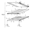
- - la figure 1 représente trois éléments d'un empilage en vue en perspective éclatée ; et
- - la figure 2 montre un échangeur de chaleur conforme à l'invention après montage et serrage des éléments entre les poteaux.
- - Figure 1 shows three elements of a stack in exploded perspective view; and
- - Figure 2 shows a heat exchanger according to the invention after mounting and tightening of the elements between the posts.
Un échangeur de chaleur conforme à l'invention peut théoriquement être constitué par un empilage d'un nombre quelconque d'éléments A, B, C... Sur la figure 1, on n'en a représenté que trois, ce qui est suffisant pour expliquer l'invention.A heat exchanger according to the invention can theoretically be constituted by a stack of any number of elements A, B, C ... In FIG. 1, only three have been shown, which is sufficient to explain the invention.
Chacun de ces éléments est constitué d'une plaque ondulée 1 à ondulations parallèles entre elles, et d'une plaque plane 2 en contact avec les fonds f de ces ondulations. Les sommets s de ces mêmes ondulations viennent en contact avec la plaque plane 2 de l'élément voisin lorsque tous les éléments de l'empilage sont serrés entre des plaques d'extrémité E, pour constituer le bloc compact visible à la figure 2. Pour favoriser les échanges thermiques entre plaques planes 2 et plaques ondulées 1, les ondulations de ces dernières ont un profil trapézoïdal, c'est-à-dire que les fonds f et les sommets s sont plats et constituent la petite base de chaque trapèze.Each of these elements consists of a
Les extrémités des plaques planes 2 dont les bords sont parallèles aux ondulations de la plaque 1 correspondante sont pliées vers l'intérieur, deux fois à angle droit, selon les lignes de pliage 3 et4, de sorte à constituer des rabats 5. La distance entre les lignes 3 et 4 n'est que très légèrement supérieure à la hauteur des trapèzes précités, de sorte que les rabats 5 restent parallèles au plan des plaques planes 2. Les rabats 5 sont suffisamment larges pour couvrir une ou plusieurs ondulations. Avant serrage des différents éléments A, B, C..., on enduit toute la surface des rabats 5 d'une colle appropriée, ou de tout autre moyen de fixation, ce qui fixera, sans solution de continuité, ces rabats 5 aux zones extrêmes correspondantes 6 du dos de la plaque plane 2 de l'élément voisin. On obtiendra ainsi une parfaite isolation entre éléments successifs, sans fuites possibles, d'un élément à l'autre, au niveau des canaux extrêmes (ceux situés sous les rabats). Pour diminuer encore le risque de communication entre éléments voisins, on peut obturer les extrémités d'un ou de plusieurs de ces canaux extrêmes, par exemple à l'aide d'un mastic 7. Après montage, ces extrémités mastiquées des canaux se trouveront en outre recouvertes et protégées par les poteaux P.The ends of the
Enfin on peut noter que pour éviter les problèmes dus aux dilatations et aux tolérances de fabrication, les dimensions des plaques ondulées 1, vues en plan, sont choisies de façon à être légèrement inférieures à celles des plaques planes 2.Finally, it can be noted that to avoid the problems due to expansion and manufacturing tolerances, the dimensions of the
Claims (8)
Applications Claiming Priority (2)
| Application Number | Priority Date | Filing Date | Title |
|---|---|---|---|
| FR9202953A FR2688582B1 (en) | 1992-03-12 | 1992-03-12 | CROSS CURRENT HEAT EXCHANGER. |
| FR9202953 | 1992-03-12 |
Publications (1)
| Publication Number | Publication Date |
|---|---|
| EP0560676A1 true EP0560676A1 (en) | 1993-09-15 |
Family
ID=9427612
Family Applications (1)
| Application Number | Title | Priority Date | Filing Date |
|---|---|---|---|
| EP93400612A Withdrawn EP0560676A1 (en) | 1992-03-12 | 1993-03-10 | Cross-flow heat-exchanger |
Country Status (2)
| Country | Link |
|---|---|
| EP (1) | EP0560676A1 (en) |
| FR (1) | FR2688582B1 (en) |
Cited By (2)
| Publication number | Priority date | Publication date | Assignee | Title |
|---|---|---|---|---|
| WO1996027112A1 (en) * | 1995-03-02 | 1996-09-06 | Emitec Gesellschaft Für Emissionstechnologie Mbh | Crosscurrent heat exchanger |
| EP0741273A3 (en) * | 1995-05-03 | 1997-10-01 | Enel Spa | A plate-type heat exchanger |
Citations (5)
| Publication number | Priority date | Publication date | Assignee | Title |
|---|---|---|---|---|
| US2961222A (en) * | 1957-12-06 | 1960-11-22 | Trane Co | Heat exchanger |
| GB929893A (en) * | 1960-11-18 | 1963-06-26 | Parsons C A & Co Ltd | Improvements in and relating to plate type heat exchangers |
| US3460611A (en) * | 1967-10-06 | 1969-08-12 | Gen Motors Corp | Heat exchanger of plate fin modules |
| EP0044561A2 (en) * | 1980-07-21 | 1982-01-27 | MüANYAGIPARI KUTATO INTEZET | Heat exchanger, in particular for heat exchange between gaseous fluids |
| US4858685A (en) * | 1982-12-06 | 1989-08-22 | Energigazdalkodasi Intezet | Plate-type heat exchanger |
-
1992
- 1992-03-12 FR FR9202953A patent/FR2688582B1/en not_active Expired - Fee Related
-
1993
- 1993-03-10 EP EP93400612A patent/EP0560676A1/en not_active Withdrawn
Patent Citations (5)
| Publication number | Priority date | Publication date | Assignee | Title |
|---|---|---|---|---|
| US2961222A (en) * | 1957-12-06 | 1960-11-22 | Trane Co | Heat exchanger |
| GB929893A (en) * | 1960-11-18 | 1963-06-26 | Parsons C A & Co Ltd | Improvements in and relating to plate type heat exchangers |
| US3460611A (en) * | 1967-10-06 | 1969-08-12 | Gen Motors Corp | Heat exchanger of plate fin modules |
| EP0044561A2 (en) * | 1980-07-21 | 1982-01-27 | MüANYAGIPARI KUTATO INTEZET | Heat exchanger, in particular for heat exchange between gaseous fluids |
| US4858685A (en) * | 1982-12-06 | 1989-08-22 | Energigazdalkodasi Intezet | Plate-type heat exchanger |
Cited By (2)
| Publication number | Priority date | Publication date | Assignee | Title |
|---|---|---|---|---|
| WO1996027112A1 (en) * | 1995-03-02 | 1996-09-06 | Emitec Gesellschaft Für Emissionstechnologie Mbh | Crosscurrent heat exchanger |
| EP0741273A3 (en) * | 1995-05-03 | 1997-10-01 | Enel Spa | A plate-type heat exchanger |
Also Published As
| Publication number | Publication date |
|---|---|
| FR2688582B1 (en) | 1994-12-09 |
| FR2688582A1 (en) | 1993-09-17 |
Similar Documents
| Publication | Publication Date | Title |
|---|---|---|
| FR2575279A1 (en) | PLATE HEAT EXCHANGER | |
| FR2738905A1 (en) | HEAT EXCHANGER TUBE WITH CONTOUR-CURRENT CIRCULATION CHANNELS | |
| FR2749649A1 (en) | BRAZED VEHICLE RADIATOR PROVIDED WITH AN ACCESSORY SUPPORT | |
| EP0560676A1 (en) | Cross-flow heat-exchanger | |
| EP0593360A1 (en) | Tube wall in two parts and process for manufacturing a condenser for the airconditioning of a motor vehicle | |
| FR2757258A1 (en) | Flat multi=channel tube for heat exchanger | |
| EP0686823A1 (en) | Heat exchanger, more particularly for cooling an air flow with high temperature | |
| EP1957927B1 (en) | Reinforced collector for the collecting box of a heat exchanger and collecting box comprising one such collector | |
| EP0001948A1 (en) | Fastening device for glazing elements or the like | |
| EP0780655A1 (en) | Heat exchanger with brazed header box, in particular for automotive vehicle | |
| FR2823840A1 (en) | Heat exchanger folded tube is obtained by folding metal strip over itself to define two channels separated by partition to form transverse member created by strip folded edges | |
| FR2814537A1 (en) | Heat exchanger for cooling vehicle exhaust has longitudinal partitions connected to collector boxes at each end and transverse partitions, some of which are connected to collector boxes on each side, ensuring fluid flows in one direction | |
| EP0054796B1 (en) | Modular cross-flow heat exchanger and method of manufacturing it | |
| FR2751403A1 (en) | Counterflow heat exchanger flat tube | |
| FR2809482A1 (en) | Tube matrix for motor vehicle heat exchanger has alternating first and second plates with folded edges and spacers to define crossing fluid flow channels | |
| EP2635867B1 (en) | Heat exchanger having welded plates, and plate forming a component of such a heat exchanger | |
| EP3385655A1 (en) | Heat exchanger with u-shaped flow | |
| EP0285479A1 (en) | Set for the preparation of building walls | |
| EP0876744B1 (en) | Thermal connector for an electronic card or housing | |
| WO2018060624A1 (en) | Collector box, heat exchanger and corresponding assembly method | |
| FR2810727A1 (en) | Heat exchanger tube for car radiator comprises metal strip which is bent over to form edges with space between, tube being folded inwards to form groove into which brazing flux is introduced | |
| FR2770240A1 (en) | Metal section for building wall | |
| WO2004102103A2 (en) | Heat exchanger which is intended, in particular, for a motor vehicle | |
| EP1548385A2 (en) | Heat exchange tube with two flow passages and heat exchanger provided with such tubes | |
| BE1012994A7 (en) | Polygonal pillar for the arrangement of small compartments |
Legal Events
| Date | Code | Title | Description |
|---|---|---|---|
| PUAI | Public reference made under article 153(3) epc to a published international application that has entered the european phase |
Free format text: ORIGINAL CODE: 0009012 |
|
| AK | Designated contracting states |
Kind code of ref document: A1 Designated state(s): DE GB IT SE |
|
| 17P | Request for examination filed |
Effective date: 19931112 |
|
| 17Q | First examination report despatched |
Effective date: 19940526 |
|
| STAA | Information on the status of an ep patent application or granted ep patent |
Free format text: STATUS: THE APPLICATION IS DEEMED TO BE WITHDRAWN |
|
| 18D | Application deemed to be withdrawn |
Effective date: 19950427 |