EP0563884A2 - An image forming apparatus having a filing section and a printing section - Google Patents
An image forming apparatus having a filing section and a printing section Download PDFInfo
- Publication number
- EP0563884A2 EP0563884A2 EP93105255A EP93105255A EP0563884A2 EP 0563884 A2 EP0563884 A2 EP 0563884A2 EP 93105255 A EP93105255 A EP 93105255A EP 93105255 A EP93105255 A EP 93105255A EP 0563884 A2 EP0563884 A2 EP 0563884A2
- Authority
- EP
- European Patent Office
- Prior art keywords
- documents
- taking out
- image
- reading
- read
- Prior art date
- Legal status (The legal status is an assumption and is not a legal conclusion. Google has not performed a legal analysis and makes no representation as to the accuracy of the status listed.)
- Withdrawn
Links
Images


Classifications
-
- H—ELECTRICITY
- H04—ELECTRIC COMMUNICATION TECHNIQUE
- H04N—PICTORIAL COMMUNICATION, e.g. TELEVISION
- H04N1/00—Scanning, transmission or reproduction of documents or the like, e.g. facsimile transmission; Details thereof
- H04N1/00567—Handling of original or reproduction media, e.g. cutting, separating, stacking
- H04N1/0062—Removing sheets from a stack or inputting media
- H04N1/00625—Removing sheets selectively from the top or bottom of a single stack or tray
-
- G—PHYSICS
- G03—PHOTOGRAPHY; CINEMATOGRAPHY; ANALOGOUS TECHNIQUES USING WAVES OTHER THAN OPTICAL WAVES; ELECTROGRAPHY; HOLOGRAPHY
- G03G—ELECTROGRAPHY; ELECTROPHOTOGRAPHY; MAGNETOGRAPHY
- G03G15/00—Apparatus for electrographic processes using a charge pattern
- G03G15/04—Apparatus for electrographic processes using a charge pattern for exposing, i.e. imagewise exposure by optically projecting the original image on a photoconductive recording material
- G03G15/04036—Details of illuminating systems, e.g. lamps, reflectors
- G03G15/04045—Details of illuminating systems, e.g. lamps, reflectors for exposing image information provided otherwise than by directly projecting the original image onto the photoconductive recording material, e.g. digital copiers
-
- G—PHYSICS
- G03—PHOTOGRAPHY; CINEMATOGRAPHY; ANALOGOUS TECHNIQUES USING WAVES OTHER THAN OPTICAL WAVES; ELECTROGRAPHY; HOLOGRAPHY
- G03G—ELECTROGRAPHY; ELECTROPHOTOGRAPHY; MAGNETOGRAPHY
- G03G15/00—Apparatus for electrographic processes using a charge pattern
- G03G15/22—Apparatus for electrographic processes using a charge pattern involving the combination of more than one step according to groups G03G13/02 - G03G13/20
- G03G15/221—Machines other than electrographic copiers, e.g. electrophotographic cameras, electrostatic typewriters
-
- H—ELECTRICITY
- H04—ELECTRIC COMMUNICATION TECHNIQUE
- H04N—PICTORIAL COMMUNICATION, e.g. TELEVISION
- H04N1/00—Scanning, transmission or reproduction of documents or the like, e.g. facsimile transmission; Details thereof
- H04N1/00567—Handling of original or reproduction media, e.g. cutting, separating, stacking
-
- H—ELECTRICITY
- H04—ELECTRIC COMMUNICATION TECHNIQUE
- H04N—PICTORIAL COMMUNICATION, e.g. TELEVISION
- H04N1/00—Scanning, transmission or reproduction of documents or the like, e.g. facsimile transmission; Details thereof
- H04N1/00795—Reading arrangements
-
- H—ELECTRICITY
- H04—ELECTRIC COMMUNICATION TECHNIQUE
- H04N—PICTORIAL COMMUNICATION, e.g. TELEVISION
- H04N1/00—Scanning, transmission or reproduction of documents or the like, e.g. facsimile transmission; Details thereof
- H04N1/00795—Reading arrangements
- H04N1/00798—Circuits or arrangements for the control thereof, e.g. using a programmed control device or according to a measured quantity
- H04N1/00814—Circuits or arrangements for the control thereof, e.g. using a programmed control device or according to a measured quantity according to a detected condition or state of the reading apparatus, e.g. temperature
-
- H—ELECTRICITY
- H04—ELECTRIC COMMUNICATION TECHNIQUE
- H04N—PICTORIAL COMMUNICATION, e.g. TELEVISION
- H04N1/00—Scanning, transmission or reproduction of documents or the like, e.g. facsimile transmission; Details thereof
- H04N1/21—Intermediate information storage
- H04N1/2166—Intermediate information storage for mass storage, e.g. in document filing systems
- H04N1/217—Interfaces allowing access to a single user
- H04N1/2175—Interfaces allowing access to a single user with local image input
-
- H—ELECTRICITY
- H04—ELECTRIC COMMUNICATION TECHNIQUE
- H04N—PICTORIAL COMMUNICATION, e.g. TELEVISION
- H04N1/00—Scanning, transmission or reproduction of documents or the like, e.g. facsimile transmission; Details thereof
- H04N1/32—Circuits or arrangements for control or supervision between transmitter and receiver or between image input and image output device, e.g. between a still-image camera and its memory or between a still-image camera and a printer device
- H04N1/32496—Changing the task performed, e.g. reading and transmitting, receiving and reproducing, copying
-
- H—ELECTRICITY
- H04—ELECTRIC COMMUNICATION TECHNIQUE
- H04N—PICTORIAL COMMUNICATION, e.g. TELEVISION
- H04N1/00—Scanning, transmission or reproduction of documents or the like, e.g. facsimile transmission; Details thereof
- H04N1/32—Circuits or arrangements for control or supervision between transmitter and receiver or between image input and image output device, e.g. between a still-image camera and its memory or between a still-image camera and a printer device
- H04N1/32502—Circuits or arrangements for control or supervision between transmitter and receiver or between image input and image output device, e.g. between a still-image camera and its memory or between a still-image camera and a printer device in systems having a plurality of input or output devices
- H04N1/32507—Circuits or arrangements for control or supervision between transmitter and receiver or between image input and image output device, e.g. between a still-image camera and its memory or between a still-image camera and a printer device in systems having a plurality of input or output devices a plurality of input devices
- H04N1/32512—Circuits or arrangements for control or supervision between transmitter and receiver or between image input and image output device, e.g. between a still-image camera and its memory or between a still-image camera and a printer device in systems having a plurality of input or output devices a plurality of input devices of different type, e.g. internal and external devices
-
- H—ELECTRICITY
- H04—ELECTRIC COMMUNICATION TECHNIQUE
- H04N—PICTORIAL COMMUNICATION, e.g. TELEVISION
- H04N1/00—Scanning, transmission or reproduction of documents or the like, e.g. facsimile transmission; Details thereof
- H04N1/32—Circuits or arrangements for control or supervision between transmitter and receiver or between image input and image output device, e.g. between a still-image camera and its memory or between a still-image camera and a printer device
- H04N1/32502—Circuits or arrangements for control or supervision between transmitter and receiver or between image input and image output device, e.g. between a still-image camera and its memory or between a still-image camera and a printer device in systems having a plurality of input or output devices
- H04N1/32523—Circuits or arrangements for control or supervision between transmitter and receiver or between image input and image output device, e.g. between a still-image camera and its memory or between a still-image camera and a printer device in systems having a plurality of input or output devices a plurality of output devices
- H04N1/32529—Circuits or arrangements for control or supervision between transmitter and receiver or between image input and image output device, e.g. between a still-image camera and its memory or between a still-image camera and a printer device in systems having a plurality of input or output devices a plurality of output devices of different type, e.g. internal and external devices
-
- H—ELECTRICITY
- H04—ELECTRIC COMMUNICATION TECHNIQUE
- H04N—PICTORIAL COMMUNICATION, e.g. TELEVISION
- H04N2201/00—Indexing scheme relating to scanning, transmission or reproduction of documents or the like, and to details thereof
- H04N2201/0077—Types of the still picture apparatus
- H04N2201/0081—Image reader
-
- H—ELECTRICITY
- H04—ELECTRIC COMMUNICATION TECHNIQUE
- H04N—PICTORIAL COMMUNICATION, e.g. TELEVISION
- H04N2201/00—Indexing scheme relating to scanning, transmission or reproduction of documents or the like, and to details thereof
- H04N2201/0077—Types of the still picture apparatus
- H04N2201/0082—Image hardcopy reproducer
-
- H—ELECTRICITY
- H04—ELECTRIC COMMUNICATION TECHNIQUE
- H04N—PICTORIAL COMMUNICATION, e.g. TELEVISION
- H04N2201/00—Indexing scheme relating to scanning, transmission or reproduction of documents or the like, and to details thereof
- H04N2201/0077—Types of the still picture apparatus
- H04N2201/0086—Image transceiver
-
- H—ELECTRICITY
- H04—ELECTRIC COMMUNICATION TECHNIQUE
- H04N—PICTORIAL COMMUNICATION, e.g. TELEVISION
- H04N2201/00—Indexing scheme relating to scanning, transmission or reproduction of documents or the like, and to details thereof
- H04N2201/0077—Types of the still picture apparatus
- H04N2201/0087—Image storage device
Definitions
- the present invention relates to an image forming apparatus, and particularly to a printer system having a filing section for filing (or recording) of, for example, character information and graphic information, and printing section for printing of information stored in the filing section.
- This filing system includes a display unit capable of displaying minute information and a large-capacity recording system, which enable sophisticated editing, and searching and recording functions based on a fixed filing style.
- this filing system is very expensive. In addition, it has too many functions for processing information, making it complicated to operate, with the result that a considerable period of time is required to record and search information.
- the integrated printer apparatus (hereinafter referred to as an integrated apparatus) has two modes: one is a copying mode wherein the apparatus functions as a copying apparatus, and the other is a filing mode wherein it functions as a filing apparatus.
- the integrated apparatus has a reading unit for reading information recorded on a document to be copied or filed, an image forming unit for printing out the information, and a filing unit for filing of the information read by the reading unit.
- the image forming unit includes a laser printer section for outputting information read by the reading unit and information extracted from the filing unit.
- the filing unit including a memory section (optical disk unit), stores the read information, searches the stored information, and displays it on a display section or outputs it to the image forming unit.
- a document to be copied or filed is set on a document table of the reading unit such that a face on which character or graphic information is recorded (hereinafter referred to as an information face) faces the document table.
- the information recorded on the document is read by the reading unit and copied or filed in accordance with a request by the user.
- the information recorded on the document set on the document table is read by the reading unit.
- the read information is converted to a printing signal to be output through the laser printer, and printed on a sheet of paper. If two or more copies of the document are requested, the above operation is repeated the number of times specified. If two or more documents are to be copied, one document is first copied in the above manner and replaced by another document, then the above operation is repeated.
- the information recorded on the document set on the document table is read by the reading unit.
- the read information is converted to a recording signal, and recorded on an optical disk by way of appropriate recording steps. If two or more documents are to be filed, information on one document is first filed in the above manner and the document is replaced by another document, then the above operation is repeated.
- an ADF Automatic Document Feeder
- the ADF replaces one document with another, when the first document has been completely read.
- documents can be fed consecutively one by one to the reading unit, with their information face facing the document table. As a result, the amount of time required for replacing documents to be copied or filed is reduced, since the user does not have to perform the replacing operation manually.
- documents are set on a document tray with their information faces facing the document table.
- the documents are consecutively fed into the ADF, beginning with the last page, which is positioned at the top of the stack of documents.
- a fed document is transported to a read reference position on the document table, and information recorded thereon is read as image information.
- the read image information is converted to electrical signals, which are converted to printing signals by appropriate processing.
- Information corresponding to the printing signals is printed out on a sheet of paper through a laser beam printer section.
- the sheet of paper on which the information is printed is output to a stacker tray and stacked therein, with its printed face facing in the opposite direction to the document table. If two or more copies of each document are requested, the reading and printing operations are repeated the number of times requested with respect to each document until the last document (leading page).
- the document After information on a document has been read, the document is reversed in the ADF so that the information face is facing in the opposite direction to the document table, and output to a document stacker tray, the documents being stacked in the order where the leading page and the last page are respectively positioned at the top and the bottom of the document stack.
- the printed paper sheets output to the stacker tray are also stacked in this order.
- the integrated apparatus with ADF When the integrated apparatus with ADF is used in the filing mode, information recorded on documents is read in consecutive fashion, beginning with the last page, i.e., in the same manner as in the copying mode.
- the read information is converted to electrical signals and temporarily stored in, for example, a hard disk or a D-RAM.
- the temporarily stored information is recorded in a memory medium such as an optical disk. If two or more documents are to be filed, the above reading operation is repeated with respect to each document until the leading page.
- the document After information on a document has been read, the document is reversed in the ADF so that the information face is facing in the opposite direction to the document table, and is output to a document stacker tray.
- the information on the leading page is recorded in the initial storage portion of an optical disk.
- documents are read beginning with the last page, i.e., in the same order as in the copying mode.
- the integrated apparatus with ADF is initialized in the copying mode when its power switch is turned on, and is on standby as a copying apparatus.
- the integrated apparatus when used as a filing apparatus, it must be switched from the copying mode to the filing mode. If, thereafter, the integrated apparatus is used as a copying apparatus, it must be switched from the filing mode to the copying mode.
- Another object of the present invention is to provide an image forming system which can read documents in different orders, in accordance with the processing mode is set.
- Still another object of the present invention is to provide an image forming system wherein documents which have been read in the order opposite to the original order are stacked in the original order.
- an image reading apparatus comprising: means for reading images recorded on documents; means for holding the documents on which the images to be read by the reading means are recorded; means for taking out the documents from the holding means, one by one, beginning with one of a top and a bottom sheet of the documents; and means for transporting the documents taken out by the taking out means to the reading means.
- an image forming apparatus comprising: means for reading images recorded on documents; means, including an image bearing member, for forming an image on the image bearing member based on an image read by the reading means and forming the image on a transferring member; means for holding the documents on which the images to be read by the reading means are recorded; means, having a recording medium, for storing the images read by the reading means in the recording medium; means, including a first taking out roller member for taking out a top sheet of the documents and a second taking out roller member for taking out a bottom sheet of the documents, for feeding the documents by means of the first taking out roller member when the images read by the reading means are to be formed on the image forming means, and by means of the second taking out roller member when the images are to be stored in the recording medium of the storing means; and means for transporting the documents taken out by the taking out means to the reading means.
- an image forming apparatus comprising: means for reading images recorded on documents; means for holding the documents on which the images to be read by the reading means are recorded; means, including a first taking out roller member for taking out a top sheet of the documents and a second taking out roller member for taking out a bottom sheet of the documents, for feeding the documents; means for transporting the documents taken out by the document taking out means to the reading means; means, including an image bearing member, for forming an image on the image bearing member based on an image read by the reading means and forming the image on a transferring member; means, having a recording medium which is inserted from outside, for storing the images read by the reading means in the recording medium; means for inputting image data to the image forming apparatus from an external device such as a facsimile, a host computer, and a word processor; and means for selecting one of:
- Fig. 1 is a schematic diagram showing an image forming system according to an embodiment of the present invention.
- An electrical filing and printing system 100 includes a main control unit 10, a system-bus line 20, a data-bus line 22, an image data processor unit 40, a memory unit 50, a reading section 60, a printing section 70, and a data filing section 80.
- the main control unit 10 has a CPU 11, a main memory 12, a basic I/F (interface) 13, and an auxiliary (AUX) I/F 14, and the like.
- the CPU 11 controls the units and sections included in the system 100, simultaneously or individually.
- the main memory 12 stores programs for, e.g., controlling the entire system.
- the basic I/F 13 is connected to a hard disk drive (HDD) and a flexible disk drive (FDD) for reading a great amount of data supplied from a memory medium, for example, a hard disk memory (HD) or a flexible disk memory (FD).
- the AUX I/F 14 interfaces the system 100 with an external device.
- the main memory 12, the basic I/F 13 and the AUX I/F 14 are connected to the CPU 11 through the system bus line 20.
- the CPU is connected through an interface connection (not shown) to the console panel 30 through which data and control signals are input by the user.
- the console panel 30 includes a keyboard 31 used for inputting various data and a display panel 32 for displaying various conditions.
- the main memory 12 includes a non-volatile memory for storing initializing data prestored in the system 100 when the system 100 is forwarded from the manufacturer.
- initializing data When the initializing data has been used, previously set initializing data (updated data) is stored in the non-volatile memory.
- the AUX I/F 14 receives/sends data from/to an external device (not shown), for example, a host computer or word processor.
- an external device for example, a host computer or word processor.
- specific interfaces e.g., GPIB, RS232C, and SCSI, are set in the AUX I/F 14 and connected to the host computer or word processor.
- the AUX I/F 14 is also connected to a modem MD which is connected to a communication device (not shown), for example, a facsimile and telephone set for remote-controlling the system 100.
- the system-bus line 20 transmits a large amount of signals for controlling the system 100. More specifically, it is used to control the main control unit 10, the image data processor unit 40, the memory unit 50, the reading section 60, the printing section 70, and the data filing section 80.
- the data-bus line 22 is used only to transmit data among the image data processor unit 40, the memory unit 50, the reading section 60, the printing section 70, and the filing section 80 with higher transmitting-speed, respectively.
- the image data processor unit 40 includes an image processing module 41 for processing data read through the reading section 60 on predetermined various conditions. It also includes a CODEC 42 for compressing and expanding the data.
- the memory unit 50 has a page memory 51 of a capacity corresponding to data contains several pages of A3 size paper and a buffer memory 52 for temporarily storing data.
- the reading section 60 includes a scanner unit 62 for optically reading information recorded on a document to be read and converting it to serial electrical signals.
- the section 60 also includes a scanner interface 61 for connecting the scanner unit 62 to the CPU 11.
- the scanner unit 62 is connected through the system-bus line 20 and the scanner interface 61 to the CPU 11.
- the printing section 70 contains a laser beam printer unit 72 for forming an image from data stored in the page memory 51 and outputting the image to a sheet of paper P as a hard copy.
- the section 70 has a printer interface 71 for connecting the printer unit 72 to the CPU 11.
- the laser beam printer unit 72 is connected to the CPU 11 through the system-bus line 20 and the printer interface 71.
- the filing section 80 includes an optical disk apparatus 82 for storing various data, which is read through the scanner unit 62 or supplied from an external device (not shown), in a large-capacity recording medium such as an optical disk.
- the section 80 further includes a disk detector 83 for detecting whether the disk apparatus 82 is set or not, and a filing interface 81 for connecting the disk apparatus 82 and the disk detector 83 to the CPU 11.
- Fig. 2 schematically shows a mechanical portion of the electrical filing and printing system 100 shown in Fig. 1.
- the scanner unit 62 has a document table 120, a first carriage 121, a second carriage 122, a reading unit 129 including a focus lens 127 and a CCD sensor 128, and an ADF (Automatic Document Feeder) 106 for consecutively supplying documents, which should be copied or filed, to the document table 120.
- ADF Automatic Document Feeder
- the laser beam printer unit 72 contains a laser optical unit 240 and an image forming section 239 for printing an image to a sheet of paper P serving as a recording medium by a electrophotography process.
- the optical disk apparatus 82 of the data filing section 80 includes an optical disk member 333 as a memory medium, a disk driving motor 334 for driving the disk member 333, an optical head device (not shown) for recording/reading data in/from the disk member 333, and a disk unit controller 335.
- the ADF 106 has a document tray 107 on which a plurality of documents D are set so that information faces face the table and a document detector 117 for detecting whether documents D are set on the document tray 107.
- the ADF 106 contains a picking-up roller 108 for picking the documents D set on the document tray 107 beginning with the last page (the top sheet), and a feeding roller 119 for picking the documents beginning with the leading page (the bottom sheet).
- the ADF 106 further contains a transporter unit 118 for transporting the documents D supplied through the rollers 108 and 119 to the document table 120.
- the ADF 106 includes an upper and lower transporting roller units 109 and 110, an aligning roller 111, a transporting belt 112, and a document stopper 113.
- the upper transporting roller unit 109 transports documents D picked up by the picking up roller 108 one by one
- the lower transporting roller unit 110 transports documents D picked up by the feeding roller 119 one by one.
- a document D supplied by the roller unit 109 or 110 is guided by the aligning roller 111 to the transporter unit 118.
- the transporter unit 118 includes the transporting belt 112 for transporting a document D.
- the document D transported by the belt 112 is stopped at a reference position of the table 120 by the document stopper 113 which is located near the reference position.
- the upper transporting roller unit 109 is constituted by a feeding roller 109a (upper) and a separator roller 109b (lower).
- the lower transporting roller unit 110 is constituted by a feeding roller 110a (lower) and a separator roller 110b (upper).
- the feeding roller 109a (upper) and the separator roller 109b (lower) extend along an axis perpendicular to the direction in which a piece of the document D is transmitted, such that they can be pressed against each other.
- the rollers are arranged parallel to each other and forced by springs (not shown) in directions so as to form an appropriate gap therebetween.
- the rollers can be pressed against each other by solenoids which force the rollers in the opposite directions forced by the springs.
- the feeding roller 110a (lower) and the separator roller 110b (upper) are arranged in the same manner as the rollers 109a and 109b.
- the feeding roller 109a, the picking up roller 108, the feeding roller 110a, and the feeding roller 119 are rotated in the same direction.
- the separator roller 109b and the separator roller 110b which can respectively be pressed against the feeding roller 109a and the feeding roller 110a, are rotated in the opposite direction.
- the ADF 106 further includes first and second document stacker trays 115 and 116, first and second outputting roller 114a and 114b, a sub-outputting roller 160, and a separating gate 161.
- Documents D picked up by the picking-up roller 108 beginning with the last page are consecutively scanned and stacked on the first document stacker tray 115.
- Documents D picked up by the feeding roller 108 beginning with the leading page are consecutively scanned and stacked on the second document stacker tray 116.
- the first and second outputting rollers 114a and 114b are interposed between the transporting belt 112 and the tray 115, and consecutively transports the scanned documents to the tray 115.
- the sub-outputting roller 160 is interposed between the transporting belt 112 and the tray 116, and transports the scanned documents to the tray 116.
- the separating gate 161 for separating the documents to the respective trays.
- documents D are placed on the document table 120 with its information face facing the document table.
- the document detector 117 detects that documents D are placed on the document tray 107.
- the feeding roller 109a and the separator roller 109b of the upper transporting roller unit 109 are moved toward separation points Q (each) in directions indicated by arrows S by means of the solenoids and the link.
- the rollers 109b and 109a each of the upper unit 109 are pressed against each other.
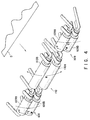
- the picking up roller 108 When the picking up roller 108 is moved by a solenoid (not shown) in a direction indicated by an arrow T, it is brought into contact with documents D. Then, the picking up roller 108 is rotated in a direction indicated by an arrow U, with the result that the last (top) sheet of the documents D is picked up. Documents D picked up from the tray 107 by the roller 108 are guided to the upper transporting roller unit 109. The documents D are separated one by one by the feeding roller 109a rotating in a direction of an arrow V and the feeding roller 109b rotating in a direction of an arrow W, and transported to the aligning roller 111. Thus, the documents D are consecutively transported to the document table 120 of the scanner unit 62 in the order from the last page to the first page, i.e., the top sheet to the bottom sheet.
- the piece of document D transported to the aligning roller 111 is temporarily stopped, and aligned if slanted during the transport. Thereafter, the document D is transmitted to the transporter unit 118. In the transporter unit 118, the document D is transported by the transporting belt 112 until it abuts against the document stopper 113.
- each of the documents D is supplied through the ADF 106 to the document table 120 such that the leftmost side of each document D is located in a substantially central portion of the leftmost side of the table.
- the piece of document D is pressed against the document table 120 by the transporting belt 112 of the transporting unit 118 and radiated by a lamp 123.
- Light reflected by the document D travels through mirrors 144, 125, and 126 and a focus lens 127 and is focused on a line CCD sensor 128 in which a plurality of light receiving elements are arranged substantially in one line.
- the first carriage 121 includes the mirror 144, a luminous energy sensor (not shown) for detecting luminous energy emitted from the lamp 123, and a heater (not shown) for warming and for keeping the temperature of the lamp constant.
- the mirrors 125 and 126 are disposed on the second carriage 122. The first and second carriages 121 and 122 are moved in parallel to the document table 120 at relative speeds of 2:1.
- the first and second carriages 121 and 122 are moved in synchronism with a read timing signal supplied from the scanner interface 61. They are moved along the document table 120, left to right in Fig. 2, by a pulse motor (not shown) or the like.
- the moving-speed of the first and second carriages 121 and 122 are determined on the basis of the reading magnification, for example, by driving a two-phase motor at 1/2-phase energization or in a microstepping manner.
- a pulse motor is driven by a pulse motor driver (not shown).
- a pulse motor driver (not shown).
- a motor driving current having a special waveform is supplied from the motor driver to the motor, so that natural oscillation for suppressing undesirable oscillation specific to the motor can be offset.
- information recorded on the piece of document D disposed on the document table 120 is read in units of line in a direction perpendicular to the direction in which the carriages 121 and 122 are moved.
- the read information is converted to 8-bit digital data representing brightness of the information.
- the digital data is output to the buffer memory 52 of the memory unit 50 through the scanner interface 61 and the data-bus line 22.
- Information read by the scanner unit 62 is transmitted to an image processing module 41 through the scanner interface 61 and the data-bus line 22.
- the information is converted to printing signals, which are transmitted to the laser beam printer unit 72 through the data-bus line 22 and the printer interface 71.
- the document D is further transported by the transporting belt 112 to the first outputting roller 114a, and then discharged to the first document stacker tray 115 through the second outputting roller 114b, so that the information face is visible (facing upward).
- the above-described operation is repeated until all the documents D set on the document tray 107 are fed to the first document stacker tray 115.
- the documents D after reading are stacked on the stacker tray 115, with their information faces facing upward.
- the documents D are stacked on the stacker tray 115 in the same order same as in the document tray 107, i.e., from the leading page to the last page, although the information faces of the documents D face in the opposite direction.
- the document detector 117 detects that documents D are placed on the document tray 107.
- the feeding roller 110a and the separator roller 110b of the lower transporting roller unit 110 are moved toward the separating point Q in directions indicated by arrows S by means of the solenoids and the link.
- the rollers 110a and 110b each of the lower unit 110 are pressed against each other.
- the picking up roller 108 When the picking up roller 108 is moved by the solenoids in a direction indicated by an arrow T, the lowermost sheet of the documents D is pressed against a feeding roller 119. Then, the feeding roller 119 is rotated in a direction indicated by an arrow X, with the result that the lowermost sheet is fed. Documents D picked up from the tray 107 by the roller 119 are guided to the lower transporting roller unit 110. The documents D are separated one by one by the feeding roller 110a rotating in a direction of an arrow Y and the feeding roller 110b rotating in a direction of an arrow Z, and transported to the aligning roller 111. Then, the documents D are consecutively transported through the transporter unit 118 to the predetermined position of the document table 120 of the scanner unit 62 in the order from the leading page to the last page, i.e., the top sheet to the bottom sheet.
- the document D is further transported by the transporting belt 112 to the separating gate 161.
- the separating gate 161 is rotated to the position indicated by the solid line as shown in Fig. 7, with the result that the document D is transported to the sub-outputting roller 160, and then discharged to the second document stacker tray 116, so that the information face is not visible (facing downward).
- the above-described operation is repeated until all the documents set on the document tray 107 are fed to the second document stacker tray 116.
- the documents D which has been scanned are stacked on the stacker tray 115, in the order where the leading page is positioned at the top and the last page is positioned at the bottom, with all the information faces facing downward.
- the documents D are stacked on the stacker tray 116 in the same order as in the document tray 107, i.e., from the leading page to the last page, and the direction of the information faces are also the same as in the document tray 107.
- the information read by the scanner unit 62 is transmitted in units of line through the scanner interface 61 and the data-bus line 22 to the CODEC 42.
- the CODEC 42 compresses the information in accordance with an appropriate rule and supplies the compressed data to the optical disk apparatus 82 through the data-bus line 22 and the filing interface 81.
- the compressed data is recorded in the optical disk member 333 as pits by means of an optical head device (not shown) which is accessed to a desired position by the disk unit controller 335.
- the optical disk member 333 is driven at a desired speed by the disk drive motor 334.
- the read data is transmitted through the data-bus line 22 to the image data processor unit 40 and expanded by the CODEC 42 of the unit 40.
- the expanded data is processed by the image processing module 41 and output to the printer unit 72 through the data-bus line 22 and the printer interface 71.
- the printer unit 72 contains, as described above, the laser optical unit 240 and the image forming section 239.
- the image forming section 239 includes a photoconductor drum 246 on which an electrostatic latent image is formed by a laser beam 245, as will be described later in detail.
- a charging unit 247, a developing device 248, a transferring roller 249, a cleaning unit 250, and a discharging lamp 251 are arranged in proximity of the drum 246.
- the charging unit 247 includes a grid screen (not shown) and provides the drum 246 with a desired potential.
- the developing device 248 supplies toner, and develops the latent image on the drum 246.
- the transferring roller 249 transfers the toner image formed on the drum 246 to a sheet of paper supplied from the paper feeding section as will be described later.
- the cleaning unit 250 removes toner remaining on the drum 246 (which are not transferred to the sheet of paper).
- the discharging lamp 251 removes the latent image remaining on the drum 246.
- the transferring roller 249 includes a roller cleaner 249a for removing toner which may adhere to itself.
- the laser optical unit 240 includes a semiconductor laser element (not shown) for emitting a laser beam 245, a cylindrical lens (not shown), a beam shaping lenses (not shown) for shaping the beam spot of the laser beam 245, and a high-speed rotation motor (not shown) utilizing an air-gaped bearing. It also includes an optical deflector device 241 for deflecting the laser beam 245 and an f ⁇ lens 242 for converging the laser beam 245 with a desired converging force so that a necessary resolution can be obtained when the laser beam 245 arrives at an exposure position 246a of the drum 246. It further includes mirrors 243 and 244 for guiding the laser beam 245 to the drum 246.
- Data transmitted through the data-bus line 22 and the printer interface 22 is synchronized by means of a printing control circuit (not shown) with a read timing at which each line is read.
- the data is output to the photoconductor drum 246 as a laser beam 245, which is turned on or off based on the data (or information).
- the laser beam 245 is deflected by the optical deflector device 241 in a desired direction, and guided through the f ⁇ lens 242 and the mirrors 234 and 244 to the developing position 246a of the drum 246 to which a desirable potential is applied through the charging unit 247.
- the drum 246 is rotated by a driving motor (not shown) at a rate at which the outer surface thereof is moved at a predetermined speed.
- the laser beam 245 focuses on the drum 246 is converted to an electrostatic latent image by the drum 246.
- the latent image is transported to the developing position 246a at which the latent image on the drum 246 faces the developing device 248 as the drum rotates.
- the latent image is developed by the toner and converted to a toner image.
- the toner image is transported to a transferring point 246c at which the toner image faces the transferring roller 249.
- the toner image is transferred via the transferring roller 249 to a sheet of paper P supplied from the paper feeding section (to be described later).
- the toner which is adhered to the transferring roller 249 and not transferred to the sheet of paper P is removed by the roller cleaner 249.
- the paper feeding section includes first and second paper cassettes 251a and 251b detachably inserted in slots (not shown), and a large capacity feeder 252 preset to a mounting portion (not shown). Sheets of paper P are selectively supplied from the paper cassettes 251a and 251b and the feeder 252 to the image forming section 239.
- An elevator 252a of the feeder 252 is movable up and down in accordance with the number of the sheets of paper P mounted thereon, so that the top of the sheets is kept at substantially the same height.
- Picking-up rollers 253a, 253b, and 253c are provided on the cassettes 251a and 251b, and the feeder 252, respectively, in order to pick up sheets of paper P from the cassettes and the feeder.
- pairs of a feeding roller 254a and a separator roller 255a, a feeding roller 254b and a separator roller 255b, and a feeding roller 254c and separator roller 255c are respectively provided on cassettes 251a and 251b, and the feeder 252, in order to feed the sheets of paper P picked up by the rollers 253a, 253b, and 253c, one by one, to the image forming section 239.
- the feeding rollers 254a, 254b, and 254c respectively face the separator rollers 255a, 255b, and 255c.
- a timing roller 256 is located between the roller pairs 254a and 255a, 254b and 255b, and 254c and 255c on one hand, and the transferring roller 249 of the image forming section 239 on the other.
- the timing roller 256 aligns the sheets of paper P if slanted during the picking-up or transport operation, and transports the sheets of paper P to the transferring roller 249 at a desired timing.
- a sheet of paper P fed from one of the cassettes 251a and 251b and the feeder 252 is transported to the transferring point 246c via the timing roller 256.
- a toner image is transferred from the drum 246 to the piece of paper P.
- the sheet of paper P to which the toner image has been transferred is transported through a conveyor 257 to a fixing unit 258, wherein the toner image is fixed on the sheet of paper P.
- the sheet of paper P is discharged out of the system 100 by the outputting roller 259 and stacked on the stacker tray 270.
- Fig. 8 is a schematic view of the console panel of the image forming system.
- the console panel 30 is constituted by the keyboard 31 used to input data for an operation and the display panel 32 for displaying a state of the system, instructions of operations, and the like.
- the keyboard 31 includes a print start key 31a to start copying or filing, a ten-key pad 31b used to input data, a clear key 31c for clearing input data, an all-clear key 31d for canceling all the input data and the set mode and returning the system to the initial state, and an interrupt key 31e for temporarily stopping the current operation and maintaining the system 100 at a state in which a new input can be accepted.
- An initializing section 33 of the console panel 30 includes a copying mode set key 33a for setting the initial mode (the mode obtained immediately after a power switch (not shown) is turned on) to the copying mode, and a filing mode set key 33b for setting the initial mode to the filing mode. It also includes a mode change key 33c for inputting a switching signal for switching the initial mode.
- a mode set section 34 includes a copy mode key 34a for selecting the copy mode and a file mode key 34b for selecting the filing mode. It further includes an enter key 34c, a search key 34d, and an output key 34e. The enter key 34 is used to execute various functions in the filing mode.
- the display panel 32 is a switch panel constituted by a display section 32a formed of a liquid crystal display with back light and a touch panel 32b having a plurality of switches attached thereon. Conditions or the like displayed on the display section 32a can be selectively input by depressing corresponding portions of the panel 32.
- Fig. 9 is a flowchart for explaining processes of initializing immediately after the power switch (not shown) of the image forming system is turned on and changing modes.
- the disk detector 83 is activated to check whether an optical disk is used (first check), thereby determining whether the user intends to use the system 100 as a copying apparatus or a filing apparatus. In other words, an output of the disk detector 83 is checked to determine whether an optical disk 233 is inserted in the optical disk unit 82.
- the system 100 is switched to the filing mode, and the LED of the file mode key 34b of the mode set section 34 of the console panel 30 is turned on, thereby informing that the filing mode is set.
- a stand-by state i.e., a so-called neutral state.
- a input (read) mode is set to file data.
- the system is switched form the stand-by state to a file input state in which the above-described file input operation is performed, i.e., the documents D are fed by the ADF 106 and information on the documents is filed.
- the optical disk 333 is ejected or is not ejected (second check). If the optical disk 333 is ejected, the system 100 is switched from the filing mode to the copying mode. The copying mode is maintained until it is detected that the optical disk 333 is inserted in the optical disk apparatus 82. If the optical disk 333 is not ejected, it is checked again whether documents D are set on the ADF 106. If it is detected that documents D are set on the ADF 106, the above-described file input process is repeated.
- the display section 32a of the display panel 32 displays instructions to select either an input or search function, and the system is maintained in the stand-by state for a predetermined period of time, e.g., one minute. At the same time, an overtime is checked by measuring a time elapsed after the system has been set in the stand-by state.
- the filing mode is switched to the copying mode. Thereafter, the copying mode is maintained until the optical disk 333 is inserted in the optical disk unit 82.
- the copying mode a copying operation is started when the print start key 31a of the console panel 30 is turned on.
- the search key 34d of the mode set section 34 is turned on, the search function is selected and files recorded on the disk are searched in sequence. More specifically, data recorded in a specific portion of the optical disk 333 inserted in the optical disk apparatus 82 are read in sequence by the optical head device (not shown).
- data recorded on the disk 333 is output through the laser beam printer unit 72. More specifically, the read data is input to the CODEC 42 of the image data processor unit 40 through the data-bus line 22, and converted to printing signals by the image processing module 41. The printing signals are supplied to the printer unit 72 through the printer interface 71. In this manner, a desired image is output to a sheet of paper P.
- Fig. 10 shows a process of setting modes.
- the copying mode is automatically switched to the filing mode, or vice versa, in accordance with whether the optical disk 333 is inserted in the optical disk unit. If documents D are fed by the ADF 106, the stacker trays on which the documents D are stacked are automatically switched in accordance with the selected mode.
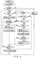
- Fig. 11 shows a modified process of initializing and changing modes shown in Figs. 9 and 10.
- data or initializing data recorded on the non-volatile memory in the main memory 12 is read via the CPU 11, thereby initializing the system 100.
- the non-volatile memory prestores data for setting the system in the copying mode, and therefore, the system is set in the copying mode by writing the data into the CPU 11.
- the LED of the copy mode key 34a is powered, which represents that the initial mode is the copying mode.
- the disk detector 83 is activated to check whether an optical disk is used (first check), thereby determining whether the user intends to use the system 100 as a copying apparatus or a filing apparatus. In other words, an output of the disk detector 83 is checked to determine whether an optical disk 333 is inserted in the optical disk unit 82.
- the filing mode is set.
- the image data input from the external device is transmitted through the data-bus line 22 to the CODEC 42 and compressed on the basis of an appropriate rule.
- the compressed data is supplied through the data-bus line 22 and the filing interface 81 to the optical disk unit 82, i.e., stored in the optical disk 333.
- the image data output from the external device is transmitted through the data-bus line 22 to the CODEC 42 and expanded on the basis of an appropriate rule.
- the expanded data is converted to printing signals by the image processing module 41.
- the printing signals are supplied through the printer interface 71 to the printer unit 72, to output a desired image to a sheet of paper P.
- Figs. 12 and 13 show a process of changing initial conditions of the system when the power switch of the processing system is turned on, for example, the condition stored in the non-volatile memory in the main memory 12.
- the display section 32a of the display panel 32 displays instructions as to whether the initializing data should be changed or not.
- the user depressed the mode change key 33c of the initializing section 33 in accordance with the instructions displayed on the display section 32a, subsequently, the copying mode set key 33a or the filing mode set key 33b.
- the initial mode can be changed.
- the initial mode of the system 100 is determined on the basis of the content of the non-volatile memory of the main memory 12 (initial data).
- the initial data of the system is set in a copying mode. If the user wishes to change the initial mode to a filing mode, the initial data stored in the non-volatile memory can be changed from the copying mode to the filing mode by turning on the filing mode set key 33b (Fig. 13).
- the disk detector 83 is activated to check whether the optical disk 333 is inserted. Thus, the user checks which mode is to be selected.
- a stand-by state i.e., a so-called neutral state.
- a input (read) mode is set to file data.
- the system is switched form the stand-by state to a file input state in which the above-described file input operation is performed, i.e., the documents D are fed by the ADF 106 and information on the documents is filed.
- the display section 32a of the display panel 32 displays instructions to select either an input or search, and the system is maintained in the stand-by state for predetermined period of time, e.g., one minute. At the same time, an overtime is checked by measuring a time elapsed after the system has been set in the stand-by state.
- the enter key 34c of the mode set section 34 of the console panel 30 is turned on during the stand-by state and the filing function is selected, it is checked again whether documents D are set on the ADF 106. If the search key 34d of the mode set section 34 is turned on, the search function is selected and files recorded on the disk are searched in sequence. More specifically, data recorded in a specific portion of the optical disk 333 inserted in the optical disk unit 82 are read in sequence by the optical head device (not shown).
- the copying mode can be set by turning on the mode change key 33c of the initializing section 33, so that a copying operation can be performed.
- the display section 32a of the display panel 32 displays instructions as to whether the copying mode should be set, and the system is maintained in the stand-by state for predetermined period of time, e.g., one minute. At the same time, an overtime is checked by measuring a time elapsed after the system has been set in the stand-by state.
- the stand-by state for changing the filing mode to the copying mode is canceled. Thereafter, the initial mode of filing is maintained.
- the system 100 is changed from the filing mode to the copying mode.
- a copying operation is started by turning on the print start key 31a.
- an overtime is checked again, i.e., a time elapsed after the system has been set in the stand-by state is measured.
- the system is maintained in the copying state for one minute after the copying operation has been completed, until a next input or overtime is detected.
- the copying mode is automatically switched to the initial mode, i.e. the filing mode. Then, it is checked again whether the optical disk is set.
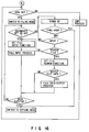
- the mode determined on the basis of the initial data is a copying mode and it is not changed, the system is operated in accordance with the flowchart shown in Fig. 16 as will be described later.
- the initial data stored in the non-volatile memory can be changed as shown in Fig. 15 from the filing mode to a copying mode by turning on the copying mode set key 33a of the initializing section.
- the system 100 is switched from the copying mode to the filing mode, and the LED of the file mode key 34b of the mode set section 34 of the console panel 30 is turned on, thereby informing that the filing mode is set.
- a stand-by state i.e., the neutral state
- a input (read) mode is set to file data.
- the system is switched form the stand-by state to a file input state in which the above-described file input operation is performed, i.e., the documents D are fed by the ADF 106 and information on the documents is filed.
- the optical disk 333 is kept inserted (second check). If the optical disk 333 is withdrawn, the system 100 is switched from the filing mode to the copying mode. The copying mode is maintained until it is detected that the optical disk 233 is inserted in the optical disk apparatus 82. If the optical disk 333 is kept inserted, it is checked again whether documents D are set on the ADF 106. If it is detected that documents D are set on the ADF 106, the above-described file input process is repeated.
- the display section 32a of the display panel 32 displays instructions to select either an input or search function, and the system is maintained in the stand-by state for a predetermined period of time, e.g., one minute. At the same time, an overtime is checked by measuring a time elapsed after the system has been set in the stand-by state.
- the filing mode is switched to the copying mode. Thereafter, the copying mode is maintained until the optical disk 333 is inserted in the optical disk apparatus 82.
- the copying mode a copying operation is started when the print start key 31a of the console panel 30 is turned on.
- data recorded on the disk 333 is output through the laser beam printer unit 72. More specifically, the read data is input to the CODEC 42 of the image data processor unit 40 through the data-bus line 22, and converted to printing signals by the image processing module 41. The printing signals are supplied to the printer unit 72 through the printer interface 71. In this manner, a desired image is output to a sheet of paper P.
- the system is operated in accordance with the flowchart shown in Fig. 14 as will be described later.
- the integrated apparatus can be changed from a copying mode to a filing mode only by setting recording medium on the storage means. Therefore, a manual operation of switching the modes is unnecessary.
- documents can be fed in the order suitable for the filing mode only by setting recording medium on the storage means.
- the documents fed in the order suitable for the filing mode are stacked on the stacker tray in the same order as initially set on the document tray.
- the image forming system comprises a document pick-up mechanism for feeding documents beginning with either the top sheet or the bottom sheet.
- the present invention is not limited to these embodiments but can be variously modified within the spirit and scope of the invention.
Abstract
Description
- The present invention relates to an image forming apparatus, and particularly to a printer system having a filing section for filing (or recording) of, for example, character information and graphic information, and printing section for printing of information stored in the filing section.
- In recent years, the amount of office space used for storing information has grown due to the increase in the amount of character and graphic information to be processed (hereinafter referred to as documents). To alleviate this situation, an information filing system utilizing a disk memory system (optical disk system) has been developed.
- This filing system includes a display unit capable of displaying minute information and a large-capacity recording system, which enable sophisticated editing, and searching and recording functions based on a fixed filing style.
- However, this filing system is very expensive. In addition, it has too many functions for processing information, making it complicated to operate, with the result that a considerable period of time is required to record and search information.
- In light of this, an image forming and filing (processing) apparatus (integrated printer apparatus) incorporating an optical disk system has been developed.
- The integrated printer apparatus (hereinafter referred to as an integrated apparatus) has two modes: one is a copying mode wherein the apparatus functions as a copying apparatus, and the other is a filing mode wherein it functions as a filing apparatus.
- The integrated apparatus has a reading unit for reading information recorded on a document to be copied or filed, an image forming unit for printing out the information, and a filing unit for filing of the information read by the reading unit. The image forming unit includes a laser printer section for outputting information read by the reading unit and information extracted from the filing unit. The filing unit, including a memory section (optical disk unit), stores the read information, searches the stored information, and displays it on a display section or outputs it to the image forming unit.
- A document to be copied or filed is set on a document table of the reading unit such that a face on which character or graphic information is recorded (hereinafter referred to as an information face) faces the document table. The information recorded on the document is read by the reading unit and copied or filed in accordance with a request by the user.
- When a copying operation is requested, the information recorded on the document set on the document table is read by the reading unit. The read information is converted to a printing signal to be output through the laser printer, and printed on a sheet of paper. If two or more copies of the document are requested, the above operation is repeated the number of times specified. If two or more documents are to be copied, one document is first copied in the above manner and replaced by another document, then the above operation is repeated.
- When a filing operation is requested, the information recorded on the document set on the document table is read by the reading unit. The read information is converted to a recording signal, and recorded on an optical disk by way of appropriate recording steps. If two or more documents are to be filed, information on one document is first filed in the above manner and the document is replaced by another document, then the above operation is repeated.
- In general, an ADF (Automatic Document Feeder) is used in combination with the reading unit. The ADF replaces one document with another, when the first document has been completely read. With the ADF, documents can be fed consecutively one by one to the reading unit, with their information face facing the document table. As a result, the amount of time required for replacing documents to be copied or filed is reduced, since the user does not have to perform the replacing operation manually.
- When the integrated apparatus with ADF is used in the copying mode, documents are set on a document tray with their information faces facing the document table. The documents are consecutively fed into the ADF, beginning with the last page, which is positioned at the top of the stack of documents. A fed document is transported to a read reference position on the document table, and information recorded thereon is read as image information. The read image information is converted to electrical signals, which are converted to printing signals by appropriate processing. Information corresponding to the printing signals is printed out on a sheet of paper through a laser beam printer section. The sheet of paper on which the information is printed is output to a stacker tray and stacked therein, with its printed face facing in the opposite direction to the document table. If two or more copies of each document are requested, the reading and printing operations are repeated the number of times requested with respect to each document until the last document (leading page).
- After information on a document has been read, the document is reversed in the ADF so that the information face is facing in the opposite direction to the document table, and output to a document stacker tray, the documents being stacked in the order where the leading page and the last page are respectively positioned at the top and the bottom of the document stack. The printed paper sheets output to the stacker tray are also stacked in this order.
- When the integrated apparatus with ADF is used in the filing mode, information recorded on documents is read in consecutive fashion, beginning with the last page, i.e., in the same manner as in the copying mode. The read information is converted to electrical signals and temporarily stored in, for example, a hard disk or a D-RAM. When the information on all of the documents has been read, the temporarily stored information is recorded in a memory medium such as an optical disk. If two or more documents are to be filed, the above reading operation is repeated with respect to each document until the leading page. After information on a document has been read, the document is reversed in the ADF so that the information face is facing in the opposite direction to the document table, and is output to a document stacker tray.
- When the documents (on which character and graphic information are recorded) include an index and abstract on a leading page, the information on the leading page is recorded in the initial storage portion of an optical disk. However, when the integrated apparatus with ADF is used in the filing mode, documents are read beginning with the last page, i.e., in the same order as in the copying mode. Hence, it is necessary to rearrange the information temporarily stored in a hard disk or D-DRAM so that the information begins with the leading page when it is stored in the optical disk. Therefore, when the information on all the documents has been temporarily stored, the information is arranged in the reverse order to that of the read information.
- The above situation is disadvantageous, since it necessitates that a hard disk or D-RAM of increased memory capacity be used and increases the time required to store all the information in the optical disk. In addition, because the document stacker tray is used to stock documents to be copied and documents to be filed after reading operations, therefore if a copying operation is interrupted by a filing operation or vice versa, documents to be filed and documents to be copied may be mixed together on the document stacker tray.
- Further, the integrated apparatus with ADF is initialized in the copying mode when its power switch is turned on, and is on standby as a copying apparatus. However, when the integrated apparatus is used as a filing apparatus, it must be switched from the copying mode to the filing mode. If, thereafter, the integrated apparatus is used as a copying apparatus, it must be switched from the filing mode to the copying mode.
- It is accordingly an object of the present invention to provide an image forming system which can switch from one processing mode to another processing mode based on procedures specific to the respective processing modes.
- Another object of the present invention is to provide an image forming system which can read documents in different orders, in accordance with the processing mode is set.
- Still another object of the present invention is to provide an image forming system wherein documents which have been read in the order opposite to the original order are stacked in the original order.
- To achieve the above objects, according to an aspect of the present invention, there is provided an image reading apparatus comprising:
means for reading images recorded on documents;
means for holding the documents on which the images to be read by the reading means are recorded;
means for taking out the documents from the holding means, one by one, beginning with one of a top and a bottom sheet of the documents; and
means for transporting the documents taken out by the taking out means to the reading means. - According to another aspect of the present invention, there is provided an image forming apparatus comprising:
means for reading images recorded on documents;
means, including an image bearing member, for forming an image on the image bearing member based on an image read by the reading means and forming the image on a transferring member;
means for holding the documents on which the images to be read by the reading means are recorded;
means, having a recording medium, for storing the images read by the reading means in the recording medium; means, including a first taking out roller member for taking out a top sheet of the documents and a second taking out roller member for taking out a bottom sheet of the documents, for feeding the documents by means of the first taking out roller member when the images read by the reading means are to be formed on the image forming means, and by means of the second taking out roller member when the images are to be stored in the recording medium of the storing means; and means for transporting the documents taken out by the taking out means to the reading means. According to further aspect of the present invention, there is provided an image forming apparatus comprising: means for reading images recorded on documents; means for holding the documents on which the images to be read by the reading means are recorded; means, including a first taking out roller member for taking out a top sheet of the documents and a second taking out roller member for taking out a bottom sheet of the documents, for feeding the documents;
means for transporting the documents taken out by the document taking out means to the reading means;
means, including an image bearing member, for forming an image on the image bearing member based on an image read by the reading means and forming the image on a transferring member;
means, having a recording medium which is inserted from outside, for storing the images read by the reading means in the recording medium;
means for inputting image data to the image forming apparatus from an external device such as a facsimile, a host computer, and a word processor; and
means for selecting one of: - a) causing the storing means to store the image data input through the inputting means in the recording medium, when the recording medium is inserted in the storing means and no document is set on the holding means;
- b) causing the second taking out roller member to take out a bottom sheet of the documents stacked on the holding means, the reading means to read an image on the bottom sheet of the documents, and the forming means to form the image read by the reading means, when the recording medium is inserted in the storing means and no document is set on the holding means;
- c) activating the forming means, when image data is input through the inputting means in a state where no recording medium is inserted in the storing means and no document is set on the holding means, to form the image on the basis of the image data input through the inputting means; and
- d) causing the first taking out roller member to take out a top sheet of the documents stacked on the holding means, the reading means to read an image on the top sheet of the document, and the forming means to form the image read by the reading means, when the documents are set on the holding means in a state where no recording medium is inserted in the storing means.
- This invention can be more fully understood from the following detailed description when taken in conjunction with the accompanying drawings, in which:
- Fig. 1 is a schematic block diagram showing an image forming system according to an embodiment of the present invention;
- Fig. 2 is a schematic sectional view showing a mechanical portion of the image forming system shown in Fig. 1;
- Fig. 3 is a side view for explaining a first feeding operation of the image forming system shown in Figs. 1 and 2;
- Fig. 4 is a schematic view for explaining more specifically the first feeding operation shown in Fig. 3;
- Fig. 5 is a side view for explaining a second feeding operation of the image forming system shown in Figs. 1 and 2;
- Fig. 6 is a schematic view for explaining more specifically the second feeding operation shown in Fig. 5;
- Fig. 7 is a schematic view for explaining a document-discharging operation of the system shown in Figs. 1 to 6;
- Fig. 8 is a schematic plan view showing a console panel of the system shown in Figs. 1 to 7;
- Fig. 9 is a flowchart for explaining a process of initializing immediately after the power switch of the image forming system is turned on and a process of changing modes;
- Fig. 10 is a flowchart for explaining a process of setting modes;
- Fig. 11 is a flowchart for explaining a process in which an external input is applied to the process shown in Fig. 9;
- Fig. 12 is a flowchart showing initializing and mode-setting processes which are different from those shown in Figs. 9 and 10; and
- Figs. 13 to 16 are flowcharts for explaining processes which follow the processes shown in Fig. 12, wherein:
- Fig. 13 shows a process of changing an initial mode when the initial mode is a copying mode;
- Fig. 14 shows a process of setting a filing mode when a request of changing the mode is input;
- Fig. 15 shows a process of changing an initial mode when the initial mode is a filing mode; and
- Fig. 16 shows a process of setting a copying mode when a request of changing the mode is input.
- Fig. 1 is a schematic diagram showing an image forming system according to an embodiment of the present invention.
- An electrical filing and
printing system 100 includes amain control unit 10, a system-bus line 20, a data-bus line 22, an imagedata processor unit 40, amemory unit 50, areading section 60, aprinting section 70, and adata filing section 80. - The
main control unit 10 has a CPU 11, amain memory 12, a basic I/F (interface) 13, and an auxiliary (AUX) I/F 14, and the like. The CPU 11 controls the units and sections included in thesystem 100, simultaneously or individually. Themain memory 12 stores programs for, e.g., controlling the entire system. The basic I/F 13 is connected to a hard disk drive (HDD) and a flexible disk drive (FDD) for reading a great amount of data supplied from a memory medium, for example, a hard disk memory (HD) or a flexible disk memory (FD). The AUX I/F 14 interfaces thesystem 100 with an external device. Themain memory 12, the basic I/F 13 and the AUX I/F 14 are connected to the CPU 11 through the system bus line 20. - The CPU is connected through an interface connection (not shown) to the
console panel 30 through which data and control signals are input by the user. Theconsole panel 30 includes akeyboard 31 used for inputting various data and adisplay panel 32 for displaying various conditions. - The
main memory 12 includes a non-volatile memory for storing initializing data prestored in thesystem 100 when thesystem 100 is forwarded from the manufacturer. When the initializing data has been used, previously set initializing data (updated data) is stored in the non-volatile memory. - The AUX I/
F 14 receives/sends data from/to an external device (not shown), for example, a host computer or word processor. For this purpose, specific interfaces, e.g., GPIB, RS232C, and SCSI, are set in the AUX I/F 14 and connected to the host computer or word processor. The AUX I/F 14 is also connected to a modem MD which is connected to a communication device (not shown), for example, a facsimile and telephone set for remote-controlling thesystem 100. - The system-bus line 20 transmits a large amount of signals for controlling the
system 100. More specifically, it is used to control themain control unit 10, the imagedata processor unit 40, thememory unit 50, thereading section 60, theprinting section 70, and thedata filing section 80. - The data-bus line 22 is used only to transmit data among the image
data processor unit 40, thememory unit 50, thereading section 60, theprinting section 70, and thefiling section 80 with higher transmitting-speed, respectively. - The image
data processor unit 40 includes animage processing module 41 for processing data read through thereading section 60 on predetermined various conditions. It also includes aCODEC 42 for compressing and expanding the data. - The
memory unit 50 has apage memory 51 of a capacity corresponding to data contains several pages of A3 size paper and abuffer memory 52 for temporarily storing data. - The
reading section 60 includes ascanner unit 62 for optically reading information recorded on a document to be read and converting it to serial electrical signals. Thesection 60 also includes ascanner interface 61 for connecting thescanner unit 62 to the CPU 11. Thescanner unit 62 is connected through the system-bus line 20 and thescanner interface 61 to the CPU 11. - The
printing section 70 contains a laserbeam printer unit 72 for forming an image from data stored in thepage memory 51 and outputting the image to a sheet of paper P as a hard copy. Thesection 70 has aprinter interface 71 for connecting theprinter unit 72 to the CPU 11. The laserbeam printer unit 72 is connected to the CPU 11 through the system-bus line 20 and theprinter interface 71. - The
filing section 80 includes anoptical disk apparatus 82 for storing various data, which is read through thescanner unit 62 or supplied from an external device (not shown), in a large-capacity recording medium such as an optical disk. Thesection 80 further includes adisk detector 83 for detecting whether thedisk apparatus 82 is set or not, and afiling interface 81 for connecting thedisk apparatus 82 and thedisk detector 83 to the CPU 11. - Fig. 2 schematically shows a mechanical portion of the electrical filing and
printing system 100 shown in Fig. 1. - The
scanner unit 62 has a document table 120, a first carriage 121, a second carriage 122, a reading unit 129 including a focus lens 127 and a CCD sensor 128, and an ADF (Automatic Document Feeder) 106 for consecutively supplying documents, which should be copied or filed, to the document table 120. - The laser
beam printer unit 72 contains a laseroptical unit 240 and animage forming section 239 for printing an image to a sheet of paper P serving as a recording medium by a electrophotography process. - The
optical disk apparatus 82 of thedata filing section 80 includes anoptical disk member 333 as a memory medium, a disk driving motor 334 for driving thedisk member 333, an optical head device (not shown) for recording/reading data in/from thedisk member 333, and adisk unit controller 335. - The
ADF 106 has adocument tray 107 on which a plurality of documents D are set so that information faces face the table and adocument detector 117 for detecting whether documents D are set on thedocument tray 107. TheADF 106 contains a picking-uproller 108 for picking the documents D set on thedocument tray 107 beginning with the last page (the top sheet), and afeeding roller 119 for picking the documents beginning with the leading page (the bottom sheet). TheADF 106 further contains atransporter unit 118 for transporting the documents D supplied through therollers - The
ADF 106 includes an upper and lower transportingroller units roller 111, a transportingbelt 112, and adocument stopper 113. The upper transportingroller unit 109 transports documents D picked up by the picking uproller 108 one by one, and the lower transportingroller unit 110 transports documents D picked up by the feedingroller 119 one by one. A document D supplied by theroller unit roller 111 to thetransporter unit 118. Thetransporter unit 118 includes the transportingbelt 112 for transporting a document D. The document D transported by thebelt 112 is stopped at a reference position of the table 120 by thedocument stopper 113 which is located near the reference position. - The upper transporting
roller unit 109 is constituted by a feeding roller 109a (upper) and aseparator roller 109b (lower). The lower transportingroller unit 110 is constituted by a feeding roller 110a (lower) and aseparator roller 110b (upper). - The feeding roller 109a (upper) and the
separator roller 109b (lower) extend along an axis perpendicular to the direction in which a piece of the document D is transmitted, such that they can be pressed against each other. The rollers are arranged parallel to each other and forced by springs (not shown) in directions so as to form an appropriate gap therebetween. The rollers can be pressed against each other by solenoids which force the rollers in the opposite directions forced by the springs. The feeding roller 110a (lower) and theseparator roller 110b (upper) are arranged in the same manner as therollers 109a and 109b. - The feeding roller 109a, the picking up
roller 108, the feeding roller 110a, and the feedingroller 119 are rotated in the same direction. Theseparator roller 109b and theseparator roller 110b, which can respectively be pressed against the feeding roller 109a and the feeding roller 110a, are rotated in the opposite direction. - The
ADF 106 further includes first and seconddocument stacker trays second outputting roller 114a and 114b, asub-outputting roller 160, and a separatinggate 161. Documents D picked up by the picking-uproller 108 beginning with the last page are consecutively scanned and stacked on the firstdocument stacker tray 115. Documents D picked up by the feedingroller 108 beginning with the leading page are consecutively scanned and stacked on the seconddocument stacker tray 116. The first andsecond outputting rollers 114a and 114b are interposed between the transportingbelt 112 and thetray 115, and consecutively transports the scanned documents to thetray 115. Thesub-outputting roller 160 is interposed between the transportingbelt 112 and thetray 116, and transports the scanned documents to thetray 116. The separatinggate 161 for separating the documents to the respective trays. - An operation of the
system 100 will be described below. - In reading information of the documents D, documents D are placed on the document table 120 with its information face facing the document table.
- In a copying mode, if documents D are supplied through the
ADF 106, thedocument detector 117 detects that documents D are placed on thedocument tray 107. As a result, as shown in Figs. 3 and 4, the feeding roller 109a and theseparator roller 109b of the upper transportingroller unit 109 are moved toward separation points Q (each) in directions indicated by arrows S by means of the solenoids and the link. Therollers 109b and 109a each of theupper unit 109 are pressed against each other. - When the picking up
roller 108 is moved by a solenoid (not shown) in a direction indicated by an arrow T, it is brought into contact with documents D. Then, the picking uproller 108 is rotated in a direction indicated by an arrow U, with the result that the last (top) sheet of the documents D is picked up. Documents D picked up from thetray 107 by theroller 108 are guided to the upper transportingroller unit 109. The documents D are separated one by one by the feeding roller 109a rotating in a direction of an arrow V and the feedingroller 109b rotating in a direction of an arrow W, and transported to the aligningroller 111. Thus, the documents D are consecutively transported to the document table 120 of thescanner unit 62 in the order from the last page to the first page, i.e., the top sheet to the bottom sheet. - The piece of document D transported to the aligning
roller 111 is temporarily stopped, and aligned if slanted during the transport. Thereafter, the document D is transmitted to thetransporter unit 118. In thetransporter unit 118, the document D is transported by the transportingbelt 112 until it abuts against thedocument stopper 113. - Information is read from the documents D as follows. First, each of the documents D is supplied through the
ADF 106 to the document table 120 such that the leftmost side of each document D is located in a substantially central portion of the leftmost side of the table. The piece of document D is pressed against the document table 120 by the transportingbelt 112 of the transportingunit 118 and radiated by a lamp 123. - Light reflected by the document D travels through mirrors 144, 125, and 126 and a focus lens 127 and is focused on a line CCD sensor 128 in which a plurality of light receiving elements are arranged substantially in one line.
- The first carriage 121 includes the mirror 144, a luminous energy sensor (not shown) for detecting luminous energy emitted from the lamp 123, and a heater (not shown) for warming and for keeping the temperature of the lamp constant. The mirrors 125 and 126 are disposed on the second carriage 122. The first and second carriages 121 and 122 are moved in parallel to the document table 120 at relative speeds of 2:1.
- The first and second carriages 121 and 122 are moved in synchronism with a read timing signal supplied from the
scanner interface 61. They are moved along the document table 120, left to right in Fig. 2, by a pulse motor (not shown) or the like. The moving-speed of the first and second carriages 121 and 122 are determined on the basis of the reading magnification, for example, by driving a two-phase motor at 1/2-phase energization or in a microstepping manner. - A pulse motor is driven by a pulse motor driver (not shown). When the pulse motor is driven at a low speed, a motor driving current having a special waveform is supplied from the motor driver to the motor, so that natural oscillation for suppressing undesirable oscillation specific to the motor can be offset.
- In the manner as described above, information recorded on the piece of document D disposed on the document table 120 is read in units of line in a direction perpendicular to the direction in which the carriages 121 and 122 are moved. The read information is converted to 8-bit digital data representing brightness of the information. The digital data is output to the
buffer memory 52 of thememory unit 50 through thescanner interface 61 and the data-bus line 22. - Information read by the
scanner unit 62 is transmitted to animage processing module 41 through thescanner interface 61 and the data-bus line 22. In themodule 41, the information is converted to printing signals, which are transmitted to the laserbeam printer unit 72 through the data-bus line 22 and theprinter interface 71. - After the information is read, the document D is further transported by the transporting
belt 112 to the first outputting roller 114a, and then discharged to the firstdocument stacker tray 115 through thesecond outputting roller 114b, so that the information face is visible (facing upward). - The above-described operation is repeated until all the documents D set on the
document tray 107 are fed to the firstdocument stacker tray 115. As a result, the documents D after reading are stacked on thestacker tray 115, with their information faces facing upward. The documents D are stacked on thestacker tray 115 in the same order same as in thedocument tray 107, i.e., from the leading page to the last page, although the information faces of the documents D face in the opposite direction. - In a filing mode, if documents D are supplied through the
ADF 106, thedocument detector 117 detects that documents D are placed on thedocument tray 107. As a result, as shown in Figs. 5 and 6, the feeding roller 110a and theseparator roller 110b of the lower transportingroller unit 110 are moved toward the separating point Q in directions indicated by arrows S by means of the solenoids and the link. Therollers 110a and 110b each of thelower unit 110 are pressed against each other. - When the picking up
roller 108 is moved by the solenoids in a direction indicated by an arrow T, the lowermost sheet of the documents D is pressed against a feedingroller 119. Then, the feedingroller 119 is rotated in a direction indicated by an arrow X, with the result that the lowermost sheet is fed. Documents D picked up from thetray 107 by theroller 119 are guided to the lower transportingroller unit 110. The documents D are separated one by one by the feeding roller 110a rotating in a direction of an arrow Y and the feedingroller 110b rotating in a direction of an arrow Z, and transported to the aligningroller 111. Then, the documents D are consecutively transported through thetransporter unit 118 to the predetermined position of the document table 120 of thescanner unit 62 in the order from the leading page to the last page, i.e., the top sheet to the bottom sheet. - Thereafter, information is read by the
scanner unit 62 from each of the documents D in the same manner as in the copying mode. - After the information is read, the document D is further transported by the transporting
belt 112 to the separatinggate 161. The separatinggate 161 is rotated to the position indicated by the solid line as shown in Fig. 7, with the result that the document D is transported to thesub-outputting roller 160, and then discharged to the seconddocument stacker tray 116, so that the information face is not visible (facing downward). - The above-described operation is repeated until all the documents set on the
document tray 107 are fed to the seconddocument stacker tray 116. As a result, the documents D which has been scanned are stacked on thestacker tray 115, in the order where the leading page is positioned at the top and the last page is positioned at the bottom, with all the information faces facing downward. Thus, the documents D are stacked on thestacker tray 116 in the same order as in thedocument tray 107, i.e., from the leading page to the last page, and the direction of the information faces are also the same as in thedocument tray 107. - The information read by the
scanner unit 62 is transmitted in units of line through thescanner interface 61 and the data-bus line 22 to theCODEC 42. TheCODEC 42 compresses the information in accordance with an appropriate rule and supplies the compressed data to theoptical disk apparatus 82 through the data-bus line 22 and thefiling interface 81. - More specifically, the compressed data is recorded in the
optical disk member 333 as pits by means of an optical head device (not shown) which is accessed to a desired position by thedisk unit controller 335. Theoptical disk member 333 is driven at a desired speed by the disk drive motor 334. - On the other hand, when data recorded in the
optical disk member 333 is to be searched or output, the data recorded in a specific portion of theoptical disk member 33 is read by the optical head device. - The read data is transmitted through the data-bus line 22 to the image
data processor unit 40 and expanded by theCODEC 42 of theunit 40. The expanded data is processed by theimage processing module 41 and output to theprinter unit 72 through the data-bus line 22 and theprinter interface 71. - The
printer unit 72 contains, as described above, the laseroptical unit 240 and theimage forming section 239. - The
image forming section 239 includes aphotoconductor drum 246 on which an electrostatic latent image is formed by alaser beam 245, as will be described later in detail. A chargingunit 247, a developingdevice 248, a transferringroller 249, acleaning unit 250, and a discharginglamp 251 are arranged in proximity of thedrum 246. The chargingunit 247 includes a grid screen (not shown) and provides thedrum 246 with a desired potential. The developingdevice 248 supplies toner, and develops the latent image on thedrum 246. The transferringroller 249 transfers the toner image formed on thedrum 246 to a sheet of paper supplied from the paper feeding section as will be described later. Thecleaning unit 250 removes toner remaining on the drum 246 (which are not transferred to the sheet of paper). The discharginglamp 251 removes the latent image remaining on thedrum 246. The transferringroller 249 includes a roller cleaner 249a for removing toner which may adhere to itself. - The laser
optical unit 240 includes a semiconductor laser element (not shown) for emitting alaser beam 245, a cylindrical lens (not shown), a beam shaping lenses (not shown) for shaping the beam spot of thelaser beam 245, and a high-speed rotation motor (not shown) utilizing an air-gaped bearing. It also includes an optical deflector device 241 for deflecting thelaser beam 245 and anfϑ lens 242 for converging thelaser beam 245 with a desired converging force so that a necessary resolution can be obtained when thelaser beam 245 arrives at an exposure position 246a of thedrum 246. It further includesmirrors laser beam 245 to thedrum 246. - Data transmitted through the data-bus line 22 and the printer interface 22 is synchronized by means of a printing control circuit (not shown) with a read timing at which each line is read. The data is output to the
photoconductor drum 246 as alaser beam 245, which is turned on or off based on the data (or information). - The
laser beam 245 is deflected by the optical deflector device 241 in a desired direction, and guided through thefϑ lens 242 and themirrors drum 246 to which a desirable potential is applied through the chargingunit 247. Thedrum 246 is rotated by a driving motor (not shown) at a rate at which the outer surface thereof is moved at a predetermined speed. - The
laser beam 245 focuses on thedrum 246 is converted to an electrostatic latent image by thedrum 246. The latent image is transported to the developing position 246a at which the latent image on thedrum 246 faces the developingdevice 248 as the drum rotates. At the developing position 246a, the latent image is developed by the toner and converted to a toner image. - The toner image is transported to a transferring point 246c at which the toner image faces the transferring
roller 249. The toner image is transferred via the transferringroller 249 to a sheet of paper P supplied from the paper feeding section (to be described later). - The toner which is adhered to the transferring
roller 249 and not transferred to the sheet of paper P is removed by theroller cleaner 249. - The paper feeding section includes first and
second paper cassettes 251a and 251b detachably inserted in slots (not shown), and alarge capacity feeder 252 preset to a mounting portion (not shown). Sheets of paper P are selectively supplied from thepaper cassettes 251a and 251b and thefeeder 252 to theimage forming section 239. An elevator 252a of thefeeder 252 is movable up and down in accordance with the number of the sheets of paper P mounted thereon, so that the top of the sheets is kept at substantially the same height. - Picking-up
rollers 253a, 253b, and 253c are provided on thecassettes 251a and 251b, and thefeeder 252, respectively, in order to pick up sheets of paper P from the cassettes and the feeder. In addition, pairs of a feeding roller 254a and a separator roller 255a, a feedingroller 254b and aseparator roller 255b, and a feeding roller 254c and separator roller 255c are respectively provided oncassettes 251a and 251b, and thefeeder 252, in order to feed the sheets of paper P picked up by therollers 253a, 253b, and 253c, one by one, to theimage forming section 239. The feedingrollers 254a, 254b, and 254c respectively face theseparator rollers 255a, 255b, and 255c. - A
timing roller 256 is located between the roller pairs 254a and 255a, 254b and 255b, and 254c and 255c on one hand, and the transferringroller 249 of theimage forming section 239 on the other. Thetiming roller 256 aligns the sheets of paper P if slanted during the picking-up or transport operation, and transports the sheets of paper P to the transferringroller 249 at a desired timing. - A sheet of paper P fed from one of the
cassettes 251a and 251b and thefeeder 252 is transported to the transferring point 246c via thetiming roller 256. At the transferring point 246c, a toner image is transferred from thedrum 246 to the piece of paper P. - The sheet of paper P to which the toner image has been transferred is transported through a
conveyor 257 to afixing unit 258, wherein the toner image is fixed on the sheet of paper P. The sheet of paper P is discharged out of thesystem 100 by the outputtingroller 259 and stacked on thestacker tray 270. - Fig. 8 is a schematic view of the console panel of the image forming system.
- The
console panel 30 is constituted by thekeyboard 31 used to input data for an operation and thedisplay panel 32 for displaying a state of the system, instructions of operations, and the like. - The
keyboard 31 includes a print start key 31a to start copying or filing, a ten-key pad 31b used to input data, a clear key 31c for clearing input data, an all-clear key 31d for canceling all the input data and the set mode and returning the system to the initial state, and an interrupt key 31e for temporarily stopping the current operation and maintaining thesystem 100 at a state in which a new input can be accepted. - An initializing
section 33 of theconsole panel 30 includes a copying mode set key 33a for setting the initial mode (the mode obtained immediately after a power switch (not shown) is turned on) to the copying mode, and a filing mode set key 33b for setting the initial mode to the filing mode. It also includes a mode change key 33c for inputting a switching signal for switching the initial mode. - A mode set
section 34 includes a copy mode key 34a for selecting the copy mode and afile mode key 34b for selecting the filing mode. It further includes an enter key 34c, a search key 34d, and an output key 34e. Theenter key 34 is used to execute various functions in the filing mode. - The
display panel 32 is a switch panel constituted by a display section 32a formed of a liquid crystal display with back light and atouch panel 32b having a plurality of switches attached thereon. Conditions or the like displayed on the display section 32a can be selectively input by depressing corresponding portions of thepanel 32. - An operation of the
system 100 will now be described. - Fig. 9 is a flowchart for explaining processes of initializing immediately after the power switch (not shown) of the image forming system is turned on and changing modes.
- When the power switch of the
image processing system 100 is turned on, data (or initializing data) stored in the non-volatile memory of themain memory 12 is read by the CPU 11 of themain control unit 10, thereby initializing thesystem 100. Since the non-volatile memory prestores data for setting a copying mode when the system is forwarded from the manufacture, the data is read by the CPU 11 and the system is set at the copying mode. At this time, an LED of the copy mode key 34a of the mode setsection 34 of thecontrol panel 30 is powered, which represents that the initial mode is the copying mode. - Thereafter, the
disk detector 83 is activated to check whether an optical disk is used (first check), thereby determining whether the user intends to use thesystem 100 as a copying apparatus or a filing apparatus. In other words, an output of thedisk detector 83 is checked to determine whether an optical disk 233 is inserted in theoptical disk unit 82. - If it is detected that an
optical disk 333 is inserted, thesystem 100 is switched to the filing mode, and the LED of thefile mode key 34b of the mode setsection 34 of theconsole panel 30 is turned on, thereby informing that the filing mode is set. - Subsequently, whether documents D are set on the
ADF 106 is checked to determine whether the user intends to input information to the filing apparatus or retrieve information therefrom. - If neither input nor search is demanded, a stand-by state, i.e., a so-called neutral state, is maintained.
- If documents D are set on the
ADF 106, a input (read) mode is set to file data. - When it is confirmed that the documents D are set on the
ADF 106, the system is switched form the stand-by state to a file input state in which the above-described file input operation is performed, i.e., the documents D are fed by theADF 106 and information on the documents is filed. - When the information on all of the documents D has been filed, it is checked whether the
optical disk 333 is ejected or is not ejected (second check). If theoptical disk 333 is ejected, thesystem 100 is switched from the filing mode to the copying mode. The copying mode is maintained until it is detected that theoptical disk 333 is inserted in theoptical disk apparatus 82. If theoptical disk 333 is not ejected, it is checked again whether documents D are set on theADF 106. If it is detected that documents D are set on theADF 106, the above-described file input process is repeated. - If it is not detected that documents D are set on the
ADF 106, the display section 32a of thedisplay panel 32 displays instructions to select either an input or search function, and the system is maintained in the stand-by state for a predetermined period of time, e.g., one minute. At the same time, an overtime is checked by measuring a time elapsed after the system has been set in the stand-by state. - When one minute elapses after the system has been set in the stand-by state, the filing mode is switched to the copying mode. Thereafter, the copying mode is maintained until the
optical disk 333 is inserted in theoptical disk unit 82. In the copying mode, a copying operation is started when the print start key 31a of theconsole panel 30 is turned on. - If the enter key 34c of the mode set
section 34 of theconsole panel 30 is turned on during the stand-by state and the filing mode is selected, it is checked again whether documents D are set on theADF 106. - On the other hand, if the search key 34d of the mode set
section 34 is turned on, the search function is selected and files recorded on the disk are searched in sequence. More specifically, data recorded in a specific portion of theoptical disk 333 inserted in theoptical disk apparatus 82 are read in sequence by the optical head device (not shown). - When the file search operation is completed, instructions for the user to determine whether the searched file data should be printed or not are displayed on the display section 32a of the
display panel 32, and the stand-by state is maintained. - If it is determined to print the searched file data by turning on the output key 34e of the mode set
section 34, data recorded on thedisk 333 is output through the laserbeam printer unit 72. More specifically, the read data is input to theCODEC 42 of the imagedata processor unit 40 through the data-bus line 22, and converted to printing signals by theimage processing module 41. The printing signals are supplied to theprinter unit 72 through theprinter interface 71. In this manner, a desired image is output to a sheet of paper P. - When the printing operation is completed, the above stand-by state is maintained and the system is kept in the filing mode until a next instruction is input or an overtime is detected.
- Fig. 10 shows a process of setting modes. In the process of Fig. 10, the copying mode is automatically switched to the filing mode, or vice versa, in accordance with whether the
optical disk 333 is inserted in the optical disk unit. If documents D are fed by theADF 106, the stacker trays on which the documents D are stacked are automatically switched in accordance with the selected mode. - Fig. 11 shows a modified process of initializing and changing modes shown in Figs. 9 and 10. In the process of Fig. 11, when the power switch of the
image processing system 100 is turned on, data (or initializing data) recorded on the non-volatile memory in themain memory 12 is read via the CPU 11, thereby initializing thesystem 100. As described above with reference to Fig. 9, the non-volatile memory prestores data for setting the system in the copying mode, and therefore, the system is set in the copying mode by writing the data into the CPU 11. The LED of the copy mode key 34a is powered, which represents that the initial mode is the copying mode. - Subsequently, it is checked by the CPU 11 whether image data is input through the AUX I/
F 14 from an external device such as a facsimile, a host computer, and a word processor. - Thereafter, the
disk detector 83 is activated to check whether an optical disk is used (first check), thereby determining whether the user intends to use thesystem 100 as a copying apparatus or a filing apparatus. In other words, an output of thedisk detector 83 is checked to determine whether anoptical disk 333 is inserted in theoptical disk unit 82. - In the same manner as in the process shown in Fig. 9, if the
optical disk 333 is inserted, the filing mode is set. The image data input from the external device is transmitted through the data-bus line 22 to theCODEC 42 and compressed on the basis of an appropriate rule. The compressed data is supplied through the data-bus line 22 and thefiling interface 81 to theoptical disk unit 82, i.e., stored in theoptical disk 333. - If the
optical disk 333 is not inserted, the image data output from the external device is transmitted through the data-bus line 22 to theCODEC 42 and expanded on the basis of an appropriate rule. The expanded data is converted to printing signals by theimage processing module 41. The printing signals are supplied through theprinter interface 71 to theprinter unit 72, to output a desired image to a sheet of paper P. - Another operation of the
system 100 will now be described. - Figs. 12 and 13 show a process of changing initial conditions of the system when the power switch of the processing system is turned on, for example, the condition stored in the non-volatile memory in the
main memory 12. - When the power switch of the
image processing system 100 is turned on, data (or initializing data) is read from the non-volatile memory in themain memory 12 by the CPU 11 of themain control unit 10, thereby initializing thesystem 100. - When the
system 100 is set in a stand-by state, the display section 32a of thedisplay panel 32 displays instructions as to whether the initializing data should be changed or not. - To change the initial mode, the user depressed the mode change key 33c of the initializing
section 33 in accordance with the instructions displayed on the display section 32a, subsequently, the copying mode set key 33a or the filing mode set key 33b. Thus, the initial mode can be changed. - The initial mode of the
system 100 is determined on the basis of the content of the non-volatile memory of the main memory 12 (initial data). When the system is forwarded from the manufacture, the initial data of the system is set in a copying mode. If the user wishes to change the initial mode to a filing mode, the initial data stored in the non-volatile memory can be changed from the copying mode to the filing mode by turning on the filing mode set key 33b (Fig. 13). - An operation of the
system 100 when the initial mode is changed to the filing mode will be described. - As shown in Fig. 14, if the initial data is changed and a filing mode is input as the initial data, the
disk detector 83 is activated to check whether theoptical disk 333 is inserted. Thus, the user checks which mode is to be selected. - If it is detected that the
optical disk 333 is inserted, whether documents D are set on theADF 106 is checked. As a result, it is determined whether the user intends to input information in the filing apparatus or to search information therefrom. - If neither input nor search is demanded, a stand-by state, i.e., a so-called neutral state, is maintained.
- If documents D are set on the
ADF 106, a input (read) mode is set to file data. - When it is confirmed that documents D are set on the
ADF 106, the system is switched form the stand-by state to a file input state in which the above-described file input operation is performed, i.e., the documents D are fed by theADF 106 and information on the documents is filed. - If it is not detected that documents D are set on the
ADF 106, the display section 32a of thedisplay panel 32 displays instructions to select either an input or search, and the system is maintained in the stand-by state for predetermined period of time, e.g., one minute. At the same time, an overtime is checked by measuring a time elapsed after the system has been set in the stand-by state. - If the enter key 34c of the mode set
section 34 of theconsole panel 30 is turned on during the stand-by state and the filing function is selected, it is checked again whether documents D are set on theADF 106. If the search key 34d of the mode setsection 34 is turned on, the search function is selected and files recorded on the disk are searched in sequence. More specifically, data recorded in a specific portion of theoptical disk 333 inserted in theoptical disk unit 82 are read in sequence by the optical head device (not shown). - When the file search operation is completed, instructions for the user to determine whether the searched file data should be printed or not are displayed on the display section 32a of the
display panel 32, and the stand-by state is maintained. - If it is detected that the
optical disk 333 is not inserted and the user wishes to use thesystem 100 as a copying apparatus, the copying mode can be set by turning on the mode change key 33c of the initializingsection 33, so that a copying operation can be performed. - More specifically, when it is detected that the
optical disk 333 is not inserted, the display section 32a of thedisplay panel 32 displays instructions as to whether the copying mode should be set, and the system is maintained in the stand-by state for predetermined period of time, e.g., one minute. At the same time, an overtime is checked by measuring a time elapsed after the system has been set in the stand-by state. - When one minute elapses after the system is set in the stand-by state, the stand-by state for changing the filing mode to the copying mode is canceled. Thereafter, the initial mode of filing is maintained.
- If the copy mode key 34a of the mode set
section 34 is turned on during the stand-by state (within one minute) and the copying function is selected, thesystem 100 is changed from the filing mode to the copying mode. In the copying mode, a copying operation is started by turning on the print start key 31a. - When the copying operation is completed, an overtime is checked again, i.e., a time elapsed after the system has been set in the stand-by state is measured. The system is maintained in the copying state for one minute after the copying operation has been completed, until a next input or overtime is detected.
- When a next input or overtime is detected, the copying mode is automatically switched to the initial mode, i.e. the filing mode. Then, it is checked again whether the optical disk is set.
- If the mode determined on the basis of the initial data is a copying mode and it is not changed, the system is operated in accordance with the flowchart shown in Fig. 16 as will be described later.
- If the initial mode determined on the basis of the initial data is a filing mode, the initial data stored in the non-volatile memory can be changed as shown in Fig. 15 from the filing mode to a copying mode by turning on the copying mode set key 33a of the initializing section.
- More specifically, as shown in Fig. 16, it is checked whether an
optical disk 333 is inserted (first check), thereby determining whether the user intends to use thesystem 100 as a copying apparatus or a filing apparatus. - If it is detected that an
optical disk 333 is inserted, thesystem 100 is switched from the copying mode to the filing mode, and the LED of thefile mode key 34b of the mode setsection 34 of theconsole panel 30 is turned on, thereby informing that the filing mode is set. - Subsequently, whether documents D is set on the
ADF 106 is checked to determine whether the user intends to input information to the filing apparatus or search information therefrom. - If neither input nor search is demanded, a stand-by state, i.e., the neutral state, is maintained.
- If documents D are set on the
ADF 106, a input (read) mode is set to file data. - When it is confirmed that the documents D are set on the
ADF 106, the system is switched form the stand-by state to a file input state in which the above-described file input operation is performed, i.e., the documents D are fed by theADF 106 and information on the documents is filed. - When the information on all of the documents has been filed, it is checked whether the
optical disk 333 is kept inserted (second check). If theoptical disk 333 is withdrawn, thesystem 100 is switched from the filing mode to the copying mode. The copying mode is maintained until it is detected that the optical disk 233 is inserted in theoptical disk apparatus 82. If theoptical disk 333 is kept inserted, it is checked again whether documents D are set on theADF 106. If it is detected that documents D are set on theADF 106, the above-described file input process is repeated. - If it is not detected that documents D are set on the
ADF 106, the display section 32a of thedisplay panel 32 displays instructions to select either an input or search function, and the system is maintained in the stand-by state for a predetermined period of time, e.g., one minute. At the same time, an overtime is checked by measuring a time elapsed after the system has been set in the stand-by state. - When one minute elapses after the system has been set in the stand-by state, the filing mode is switched to the copying mode. Thereafter, the copying mode is maintained until the
optical disk 333 is inserted in theoptical disk apparatus 82. In the copying mode, a copying operation is started when the print start key 31a of theconsole panel 30 is turned on. - If the enter key 34c of the mode set
section 34 of theconsole panel 30 is turned on during the stand-by state and the filing function is selected, it is checked again whether documents D are set on theADF 106. - When the file search operation is completed, instructions for the user to determine whether the searched file data should be printed or not are displayed on the display section 32a of the
display panel 32, and the stand-by state is maintained. - If it is determined to print the searched file data by turning on the output key 34e of the mode set
section 34, data recorded on thedisk 333 is output through the laserbeam printer unit 72. More specifically, the read data is input to theCODEC 42 of the imagedata processor unit 40 through the data-bus line 22, and converted to printing signals by theimage processing module 41. The printing signals are supplied to theprinter unit 72 through theprinter interface 71. In this manner, a desired image is output to a sheet of paper P. - When the printing operation is completed, the above stand-by state is maintained and the system is kept in the filing mode until a next instruction is input or overtime is detected.
- If the initial mode determined on the basis of the initial data is a filing mode and it is not changed, the system is operated in accordance with the flowchart shown in Fig. 14 as will be described later.
- As has been described above, according to the present invention, the integrated apparatus can be changed from a copying mode to a filing mode only by setting recording medium on the storage means. Therefore, a manual operation of switching the modes is unnecessary. In addition, documents can be fed in the order suitable for the filing mode only by setting recording medium on the storage means. Moreover, the documents fed in the order suitable for the filing mode are stacked on the stacker tray in the same order as initially set on the document tray.
- In the above embodiments, the image forming system comprises a document pick-up mechanism for feeding documents beginning with either the top sheet or the bottom sheet. However, the present invention is not limited to these embodiments but can be variously modified within the spirit and scope of the invention.
Claims (9)
- An image reading apparatus (62) characterized by comprising:
means (228) for reading images recorded on documents;
means (107) for holding the documents on which the images to be read by the reading means are recorded;
means (108, 119) for taking out the documents from the holding means, one by one, beginning with one of a top and a bottom sheet of the documents; and
means (109, 110) for transporting the documents taken out by the taking out means to the reading means. - The apparatus according to claim 1, characterized in that the taking out means include a first taking out roller (108) which is brought into contact with the top sheet of the documents to take it out and a second taking out roller (119) which is brought into contact with the bottom sheet of the documents to take it out, the first and second taking out rollers being selectively activated in accordance with conditions for taking out the documents.
- The apparatus according to claim 1, characterized in that the transporting means include at least two pairs of rollers (109, 110) for limiting one by one the documents taken out by one of the first and second taking out rollers and supplied to the reading means.
- The apparatus according to claim 3, characterized in that when one of the pairs of the rollers is activated and brought into contact with each other, another one of the pairs of the rollers is opened so as not to apply a restraining force to a piece of document to be transported to the reading means.
- The apparatus according to claim 4, characterized in that an upper roller (109a) of the pair of rollers (109), positioned above the documents, which transport the piece of document supplied from the first taking out roller (108), is rotated in the same direction as the rotation of the first taking out roller, and a lower roller (109b) of the pair of rollers (109), positioned below the documents, is rotated in the opposite direction.
- The apparatus according to claim 4, characterized in that a lower roller (110a) of the pair of rollers (110), positioned below the documents, which transport the piece of document supplied from the second taking out roller (119), is rotated in the same direction as the rotation of the second taking out roller, and an upper roller (110b) of the pair of rollers (110), positioned above the documents, is rotated in the opposite direction.
- An image forming apparatus (100) characterized by comprising:
means (62) for reading images recorded on documents;
means (72), including an image bearing member (246), for forming an image on the image bearing member based on an image read by the reading means and forming the image on a transferring member (P);
means (107) for holding the documents on which the images to be read by the reading means are recorded;
means (82), having a recording medium (333), for storing the images read by the reading means in the recording medium;
means (106), including a first taking out roller member (108) for taking out a top sheet of the documents and a second taking out roller member (119) for taking out a bottom sheet of the documents, for feeding the documents by means of the first taking out roller member when the images read by the reading means are to be formed on the image forming means, and by means of the second taking out roller member when the images are to be stored in the recording medium of the storing means; and
means (109, 110) for transporting the documents taken out by the taking out means to the reading means. - The apparatus according to claim 7, characterized in that the reading means includes a first stock portion (115) for turning over and stocking the documents read by the reading means itself and a second stock portion (116) for stocking the documents without turning them over, and the documents are stacked on the first stock portion when they are fed by the first taking out roller member and on the second stock portion when they are fed by the second taking out roller member.
- An image forming apparatus (100) comprising: means (62) for reading images recorded on documents;
means (107) for holding the documents on which the images to be read by the reading means are recorded;
means (106), including a first taking out roller member (108) for taking out a top sheet of the documents and a second taking out roller member (119) for taking out a bottom sheet of the documents, for feeding the documents;
means (109, 110) for transporting the documents taken out by the document taking out means to the reading means;
means (72), including an image bearing member (246), for forming an image on the image bearing member based on an image read by the reading means and forming the image on a transferring member;
means (82), having a recording medium (333) which is inserted from outside, for storing the images read by the reading means in the recording medium;
means (14) for inputting image data to the image forming apparatus from an external device such as a facsimile, a host computer, and a word processor; and
means (11) for selecting a function in a plurality of functions of the apparatus;
characterized in that
the selecting means select one of:a) causing the storing means to store the image data input through the inputting means in the recording medium, when the recording medium is inserted in the storing means and no document is set on the holding means;b) causing the second taking out roller member to take out a bottom sheet of the documents stacked on the holding means, the reading means to read an image on the bottom sheet of the documents, and the forming means to form the image read by the reading means, when the recording medium is inserted in the storing means and no document is set on the holding means;c) activating the forming means, when image data is input through the inputting means in a state where no recording medium is inserted in the storing means and no document is set on the holding means, to form the image on the basis of the image data input through the inputting means; andd) causing the first taking out roller member to take out a top sheet of the documents stacked on the holding means, the reading means to read an image on the top sheet of the document, and the forming means to form the image read by the reading means, when the documents are set on the holding means in a state where no recording medium is inserted in the storing means.
Applications Claiming Priority (2)
| Application Number | Priority Date | Filing Date | Title |
|---|---|---|---|
| JP106221/92 | 1992-03-31 | ||
| JP10622192A JP3152732B2 (en) | 1992-03-31 | 1992-03-31 | Image forming storage device |
Publications (2)
| Publication Number | Publication Date |
|---|---|
| EP0563884A2 true EP0563884A2 (en) | 1993-10-06 |
| EP0563884A3 EP0563884A3 (en) | 1994-09-28 |
Family
ID=14428093
Family Applications (1)
| Application Number | Title | Priority Date | Filing Date |
|---|---|---|---|
| EP9393105255A Withdrawn EP0563884A3 (en) | 1992-03-31 | 1993-03-30 | An image forming apparatus having a filing section and a printing section |
Country Status (3)
| Country | Link |
|---|---|
| US (1) | US5339134A (en) |
| EP (1) | EP0563884A3 (en) |
| JP (1) | JP3152732B2 (en) |
Cited By (3)
| Publication number | Priority date | Publication date | Assignee | Title |
|---|---|---|---|---|
| EP0854630A2 (en) * | 1997-01-21 | 1998-07-22 | Xerox Corporation | An auto-function switching in a multi-functional machine |
| EP1657904A1 (en) * | 2004-11-04 | 2006-05-17 | Ricoh Company, Ltd. | Medium cover for controlling access to a portable medium inserted in an image processing apparatus |
| EP1835716A1 (en) * | 2006-03-17 | 2007-09-19 | Brother Kogyo Kabushiki Kaisha | Multifunction device with automatic operation mode selection |
Families Citing this family (16)
| Publication number | Priority date | Publication date | Assignee | Title |
|---|---|---|---|---|
| JP3167494B2 (en) * | 1993-03-24 | 2001-05-21 | 株式会社東芝 | Image forming device |
| US5606402A (en) * | 1993-12-27 | 1997-02-25 | Sharp Kabushiki Kaisha | Electrostatic image former with improved toner control grid |
| US5696917A (en) | 1994-06-03 | 1997-12-09 | Intel Corporation | Method and apparatus for performing burst read operations in an asynchronous nonvolatile memory |
| EP0691781B1 (en) * | 1994-07-07 | 2000-03-01 | Canon Kabushiki Kaisha | Copying apparatus capable of changing original feed order |
| JP3471131B2 (en) * | 1995-07-10 | 2003-11-25 | 富士写真フイルム株式会社 | Document reader |
| US5927706A (en) * | 1995-09-29 | 1999-07-27 | Canon Kabushiki Kaisha | Automatic original supplying apparatus |
| JPH09110270A (en) * | 1995-10-13 | 1997-04-28 | Canon Inc | Automatic document feeder and method |
| US5761678A (en) * | 1996-06-26 | 1998-06-02 | International Business Machines Corporation | Creation of clone storage area with identification of base storage area and deferred cloning of metadata |
| JP3554177B2 (en) * | 1997-04-23 | 2004-08-18 | キヤノン株式会社 | Output control device, output control method, storage medium |
| US6567187B1 (en) * | 1998-04-15 | 2003-05-20 | Canon Kabushiki Kaisha | Printing apparatus and feeding control method |
| JP2000069242A (en) * | 1998-04-30 | 2000-03-03 | Ricoh Co Ltd | Image reader |
| US7167255B1 (en) * | 1998-07-31 | 2007-01-23 | Canon Kabushiki Kaisha | Method for displaying desired message in display unit of data processing apparatus for various processes |
| US7277203B1 (en) * | 1999-10-18 | 2007-10-02 | Sharp Laboratories Of America, Inc. | Method of improving start-up behavior for color error diffusion digital half-toning |
| US7102767B2 (en) | 2002-07-19 | 2006-09-05 | Kabushiki Kaisha Toshiba | Print module for direct multiple image formatting and printing |
| US20100279822A1 (en) * | 2008-11-01 | 2010-11-04 | Ford John Hajime | Systems and methods for optimizing one or more audio tracks to a video stream |
| US8915496B2 (en) * | 2012-10-19 | 2014-12-23 | Foxlink Image Technology Co., Ltd. | Feeding apparatus |
Citations (3)
| Publication number | Priority date | Publication date | Assignee | Title |
|---|---|---|---|---|
| US4980717A (en) * | 1987-10-27 | 1990-12-25 | Canon Kabushiki Kaisha | Image recording method and apparatus |
| EP0434285A2 (en) * | 1989-12-18 | 1991-06-26 | Matsushita Graphic Communication Systems, Inc. | Image reading device |
| FR2665811A1 (en) * | 1990-08-08 | 1992-02-14 | Alcatel Business Systems | Ordinary-paper fax machine |
Family Cites Families (5)
| Publication number | Priority date | Publication date | Assignee | Title |
|---|---|---|---|---|
| US4604653A (en) * | 1982-10-21 | 1986-08-05 | Tokyo Shibaura Denki Kabushiki Kaisha | Document filing system |
| JPH0769654B2 (en) * | 1986-12-24 | 1995-07-31 | ミノルタ株式会社 | Multi-function machine for electronic photocopy and fax transmission |
| JPH01280962A (en) * | 1987-10-28 | 1989-11-13 | Ricoh Co Ltd | Picture processor |
| US4949949A (en) * | 1988-11-22 | 1990-08-21 | Xerox Corporation | Hybrid sequenced dadf duplexing system |
| JPH03196266A (en) * | 1989-12-25 | 1991-08-27 | Toshiba Corp | Image generation storage |
-
1992
- 1992-03-31 JP JP10622192A patent/JP3152732B2/en not_active Expired - Fee Related
-
1993
- 1993-03-16 US US08/031,846 patent/US5339134A/en not_active Expired - Fee Related
- 1993-03-30 EP EP9393105255A patent/EP0563884A3/en not_active Withdrawn
Patent Citations (3)
| Publication number | Priority date | Publication date | Assignee | Title |
|---|---|---|---|---|
| US4980717A (en) * | 1987-10-27 | 1990-12-25 | Canon Kabushiki Kaisha | Image recording method and apparatus |
| EP0434285A2 (en) * | 1989-12-18 | 1991-06-26 | Matsushita Graphic Communication Systems, Inc. | Image reading device |
| FR2665811A1 (en) * | 1990-08-08 | 1992-02-14 | Alcatel Business Systems | Ordinary-paper fax machine |
Cited By (6)
| Publication number | Priority date | Publication date | Assignee | Title |
|---|---|---|---|---|
| EP0854630A2 (en) * | 1997-01-21 | 1998-07-22 | Xerox Corporation | An auto-function switching in a multi-functional machine |
| EP0854630A3 (en) * | 1997-01-21 | 2000-01-19 | Xerox Corporation | An auto-function switching in a multi-functional machine |
| EP1657904A1 (en) * | 2004-11-04 | 2006-05-17 | Ricoh Company, Ltd. | Medium cover for controlling access to a portable medium inserted in an image processing apparatus |
| US7551297B2 (en) | 2004-11-04 | 2009-06-23 | Ricoh Company, Ltd. | Controlling access to a portable medium inserted in an image processing apparatus |
| EP1835716A1 (en) * | 2006-03-17 | 2007-09-19 | Brother Kogyo Kabushiki Kaisha | Multifunction device with automatic operation mode selection |
| US8493576B2 (en) | 2006-03-17 | 2013-07-23 | Brother Kogyo Kabushiki Kaisha | Multifunctional device with automatic switching mode |
Also Published As
| Publication number | Publication date |
|---|---|
| US5339134A (en) | 1994-08-16 |
| JPH05284307A (en) | 1993-10-29 |
| EP0563884A3 (en) | 1994-09-28 |
| JP3152732B2 (en) | 2001-04-03 |
Similar Documents
| Publication | Publication Date | Title |
|---|---|---|
| US5339134A (en) | Automatic document feeder for image forming apparatus | |
| US6751426B2 (en) | Image forming apparatus, control apparatus and control method for the same, and storage medium product | |
| JPH0795373A (en) | Image forming device | |
| JP3662685B2 (en) | Image forming apparatus | |
| JPH09163042A (en) | Image forming device and method therefor | |
| EP0785482A2 (en) | Image forming system | |
| JPH1097160A (en) | Image forming device | |
| US6667811B1 (en) | Image forming apparatus | |
| US5880851A (en) | Image processing apparatus having means to interrupt one of concurrent scanning and printing operations | |
| JPH11327217A (en) | Image forming device and method | |
| JP3658017B2 (en) | Image forming apparatus | |
| JPH09326890A (en) | Image forming device and image forming method | |
| JP3694079B2 (en) | Image forming apparatus | |
| JPH10247992A (en) | Image formation device and image formation method | |
| EP0492579A2 (en) | Image-processing system for recording an image in an IC card and for displaying the image by means of a display | |
| JP4108825B2 (en) | Image forming apparatus and image forming method | |
| JP2938135B2 (en) | Image forming storage device | |
| JPH10224606A (en) | Image forming device | |
| JPH10304110A (en) | Image forming device | |
| JPH11352844A (en) | Image forming device and image forming condition setting method in the same | |
| JPH05120359A (en) | Image forming storing and retrieving device | |
| JPH10271280A (en) | Image reader, image forming device, and image read method | |
| JP3400970B2 (en) | Image forming device | |
| JPH10210229A (en) | Image reader and image forming device | |
| JPH1097157A (en) | Image forming device |
Legal Events
| Date | Code | Title | Description |
|---|---|---|---|
| PUAI | Public reference made under article 153(3) epc to a published international application that has entered the european phase |
Free format text: ORIGINAL CODE: 0009012 |
|
| 17P | Request for examination filed |
Effective date: 19930330 |
|
| AK | Designated contracting states |
Kind code of ref document: A2 Designated state(s): DE FR GB |
|
| PUAL | Search report despatched |
Free format text: ORIGINAL CODE: 0009013 |
|
| AK | Designated contracting states |
Kind code of ref document: A3 Designated state(s): DE FR GB |
|
| STAA | Information on the status of an ep patent application or granted ep patent |
Free format text: STATUS: THE APPLICATION HAS BEEN WITHDRAWN |
|
| 18W | Application withdrawn |
Withdrawal date: 19941020 |
|
| AK | Designated contracting states |
Kind code of ref document: A1 Designated state(s): AT BE BG CH CY CZ DE DK EE ES FI FR GB GR HU IE IS IT LI LU MC NL PL PT RO SE SI SK TR |
|
| AX | Request for extension of the european patent |
Extension state: AL HR LT LV MK YU |
|
| 18W | Application withdrawn |
Effective date: 20050702 |
|
| DA1 | Application published (deleted) |