EP0564207A2 - Optical fiber connector - Google Patents
Optical fiber connector Download PDFInfo
- Publication number
- EP0564207A2 EP0564207A2 EP93302419A EP93302419A EP0564207A2 EP 0564207 A2 EP0564207 A2 EP 0564207A2 EP 93302419 A EP93302419 A EP 93302419A EP 93302419 A EP93302419 A EP 93302419A EP 0564207 A2 EP0564207 A2 EP 0564207A2
- Authority
- EP
- European Patent Office
- Prior art keywords
- plate
- cavity
- grooves
- alignment
- optical fiber
- Prior art date
- Legal status (The legal status is an assumption and is not a legal conclusion. Google has not performed a legal analysis and makes no representation as to the accuracy of the status listed.)
- Granted
Links
Images


Classifications
-
- G—PHYSICS
- G02—OPTICS
- G02B—OPTICAL ELEMENTS, SYSTEMS OR APPARATUS
- G02B6/00—Light guides; Structural details of arrangements comprising light guides and other optical elements, e.g. couplings
- G02B6/24—Coupling light guides
- G02B6/36—Mechanical coupling means
- G02B6/38—Mechanical coupling means having fibre to fibre mating means
- G02B6/3807—Dismountable connectors, i.e. comprising plugs
- G02B6/3833—Details of mounting fibres in ferrules; Assembly methods; Manufacture
- G02B6/3834—Means for centering or aligning the light guide within the ferrule
- G02B6/3838—Means for centering or aligning the light guide within the ferrule using grooves for light guides
- G02B6/3839—Means for centering or aligning the light guide within the ferrule using grooves for light guides for a plurality of light guides
Landscapes
- Physics & Mathematics (AREA)
- General Physics & Mathematics (AREA)
- Optics & Photonics (AREA)
- Mechanical Coupling Of Light Guides (AREA)
Abstract
Description
- The present invention relates to an optical fiber connector, and more particularly, to an optical fiber connector for collectively connecting a plurality of optical fibers together.
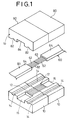
- In an optical fiber communication system, an optical fiber connector is used to connect optical fibers together. There are conventionally known optical fiber connectors such as a multi-core optical fiber connector for collectively joining a plurality of optical fibers together, in addition to a single-core optical fiber connector. Fig. 1 shows a general multi-core optical fiber connector. Tip ends of the
optical fibers optical fiber cables - The multi-core optical fiber connector comprises a
lower plate 10 and aholding plate 80. Thelower plate 10 is provided with a plurality of V-grooves 12 formed therein for accommodating the plurality ofoptical fibers 62 in an arranged manner, and anaccommodation groove 16 defined to communicate with ends of the V-grooves 12 for disposition of a coveringportion 64 of theoptical fiber cable 60.Alignment grooves 14 are defined on both sides of the V-grooves 12 for respectively holding alignment pins (not shown) to position thelower plates 10 relative to each other. Theholding plate 80 is provided with anaccommodation groove 84 corresponding to theaccommodation groove 16, andalignment grooves 82 corresponding to thealignment grooves 14. - The
optical fibers 62 are disposed in the V-grooves 12 in thelower plate 10, and thecovering portion 64 of theoptical fiber cable 60 is disposed in theaccommodation groove 16. In this condition, theholding plate 80 is laid on thelower plate 10, and thelower plate 10, theholding plate 80, thecovering portion 64 and theoptical fibers 62 are integrally secured together by use of an adhesive. The multi-core optical connectors are positioned by means of the alignment pins (not shown) integrally inserted into thealignment grooves 14 and 8, with the end faces of theoptical fibers 62 being connected together. - In such a multi-core optical connector, it is necessary to reduce variations in connection loss due to misalignment of the
optical fibers 62 and due to a variation in temperature, as much as possible. For this reason, it has been proposed that thelower plate 10 and theholding plate 80 are made of ceramics, and the V-grooves 12 and thealignment grooves 14 are cut with high machining accuracy in the lowerceramic plate 10, and thealignment grooves 82 are cut with high machining accuracy in theceramics holding plate 80. - When the
lower ceramics plate 10 is machined, however, the V-grooves 12 are first made in the entire upper surface of thelower ceramics plate 10 and then, the portions of the V-grooves 12 corresponding to a section for accommodating thecovering portion 64 and an upper portion of thelower ceramics plate 10 are removed by counterboring, thereby providing theaccommodation groove 16. - A significantly long time is required for performing this counterboring, thereby causing a considerably increased machining cost for the
lower ceramics plate 10, resulting in an expensive multi-core optical connector as a whole. Moreover, theaccommodation groove 16 is adapted for merely accommodating the coveringportion 64 therein and is not a portion requiring accuracy, and nevertheless, it accounts for a significant portion of the machining cost for thelower ceramics plate 10. Further, it is necessary to define the V-grooves 12 first in the entire surface of the lower ceramics plate including a section corresponding to theaccommodation groove 16 which will be removed later, and hence, an unnecessary machining cost is taken even for provision of the V-grooves 12. - Accordingly, it is an object of the present invention to provide an optical fiber connector which enables a plurality of optical fibers to be connected together with high accuracy and which can be manufactured at a low cost.
- According to the present invention, there is provided an optical fiber connector for a plurality of covered optical fibers, comprising:
- (a) a lower ceramics plate with a top plane surface having a plurality of V-groves, each groove for respectively holding one fiber;
- (b) an upper plate, in spaced apart combination with the lower plate, for firmly holding the optical fibers in the lower plate grooves; and
- (c) a holder having two opposed end portion in which:
- (i) a first cavity is profiled in the first end portion to accommodate the combination of the upper and lower plates; and
- (ii) a second cavity is profiled in the second end portion to accommodate the covered fibers,
- In the present invention, because the V-grooves are provided in the lower ceramics plate, the V-grooves can be machined with high accuracy. Therefore, it is possible to inhibit the generation of a connection loss and a variation in connection loss due to a variation in temperature.
- In addition, bacause the cavity for accommodation of the fiber covering portion is provided in the holder rather than in the lower ceramics plate, the machining for provision of the cavity in the lower ceramics plate is no longer required, thereby providing a reduced machining cost for the optical fiber connector.
- Preferably, the connector further comprises narrowing means disposed in the connection portion above the lower plate, for narrowing the cross section of the connection portion, whereby the fibers are loosely held in place in the grooves.
- By providing the narrowing means within the first cavity in the vicinity of the inner end of the second cavity in this manner, the optical fibers can be loosely held and temporarily fixed by the narrowing means. Therefore, there is eliminated the need for temporarily fixing the optical fibers by an adhesive tape, a double-sided adhesive tape or the like before the optical fibers are firmly held within the V-grooves by the upper plate, thereby ensuring that the optical fibers can be easily fixed.
- The narrowing means may comprise a portion of the lower plate grooves and an upper holding means disposed thereabove by a distance less than the diameter of the optical fiber, so as to narrow the cross-sectional area of the connection portion.
- The upper holding means may be made of ceramics and the first cavity may be profiled to also accommodate the upper holding means. The upper holding means may also be monolithically integral with the holer.
- Preferably, the upper holding means is displaced away from the second cavity so as to narrow the cross-section of the connection portion at a position away from the second cavity.
- With such construction, the V-grooves are exposed between the upper means and the inner end of the second cavity. The exposed V-grooves serve as guides, thereby facilitating the introduction of the fibers through the second cavity.
- Preferably, the upper plate is made of ceramics. The holder may be made of resin or metal.
- Preferably, the connector further comprises alignment means having:
- (i) an alignment pin;
- (ii) an alignment plate; and
- (iii) two complementary grooves, one profiled in the alignment plate and the other profiled in the top plane surface of the lower plate, so that in combination, the alignment plate and the lower plate firmly hold the alignment pin within the alignment grooves, and the first cavity is profiled to accommodate the alignment means so that the alignment pin is firmly held in place.
- By providing such an alignment, the optical fiber connectors can be aligned with each other with high accuracy.
- The above and further optional features and advantages of the present invention will become more apparent from the following detailed description taken in conjunction with the accompanying drawings, wherein:
- Fig. 1 is a schematic exploded perspective view showing a conventional optical fiber connector;
- Fig. 2 is a schematic exploded perspective view showing an optical fiber connector according to a first embodiment of the present invention;
- Fig. 3 is a cross-sectional view taken along a line X-X in Fig.2;
- Fig. 4 is a cross-sectional view taken along a line Y-Y in Fig.2;
- Fig. 5 is an enlarged front view of the optical fiber connector according to the first embodiment of the present invention;
- Fig. 6 is a schematic exploded perspective view showing an optical fiber connector according to a second embodiment of the present invention;
- Fig. 7 is a cross-sectional view taken along a line X-X in Fig. 6;
- Fig. 8 is a cross-sectional view taken along a line Y-Y in Fig. 6;
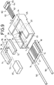
- Fig. 9 is a schematic exploded perspective view showing an optical fiber connector according to a third embodiment of the present invention;
- Fig. 10 is a cross-sectional view taken along a line X-X in Fig. 9;
- Fig. 11 is a cross-sectional view taken along a line Y-Y in Fig. 9;
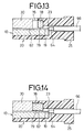
- Fig. 12 is a schematic exploded perspective view showing an optical fiber connector according to a fourth embodiment of the present invention;
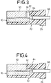
- Fig. 13 is a cross-sectional view taken along a line X-X in Fig. 12;
- Fig. 14 is a cross-sectional view taken along a line Y-Y in Fig. 13;
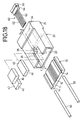
- Fig. 15 is a schematic exploded perspective view showing an optical fiber connector according to a fifth embodiment of the present invention;
- Fig. 16 is a cross-sectional view taken along a line X-X in Fig. 15;
- Fig. 17 is a cross-sectional view taken along a line Y-Y in Fig. 15;
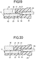
- Fig. 18 is a schematic exploded perspective view showing an optical fiber connector according to a sixth embodiment of the present invention;
- Fig. 19 is a cross-sectional view taken along a line X-X in Fig. 18;
- Fig. 20 is a cross-sectional view taken along a line Y-Y in Fig. 18;
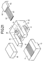
- Fig. 21 is a schematic exploded perspective view showing an optical fiber connector according to a seventh embodiment of the present invention; and
- Fig. 22 is a cross-sectional view taken along a line X-X in Fig. 21.
- Referring to Figs 2 to 5, an optical fiber connector according to a first embodiment of the present invention comprises a
lower ceramics plate 10 having a plurality of V-grooves 12 each adapted for holding each ofoptical fibers 62 of a tape-like fiber cable 60 in line, and analignment grooves 14 for holding an alignment pins 50; aceramics holding plate 30 for holding theoptical fibers 62 in said V-grooves 12; aceramics alignment plate 40 for supporting thealignment pin 50 at three points by cooperation with opposed wall surfaces constituting thealignment groove 14; and aresinous socket 20 which is a holder. - The
lower ceramics plate 10 has atop plane surface 11, the plurality ofgrooves 12 provided at its central portion, and thealignment grooves 14 which are provided in the top plane surfaces 11 on the opposite sides of the V-grooves 12 and into which the alignment pins 50 are to be inserted. The holdingplate 30 is of a planar plate-like configuration, and thealignment plates 40 abut against opposite sides of the holdingplate 30. Thealignment plate 40 is of a substantially planar plate-like configuration and has analignment groove 42 provided in its bottom surface and corresponding to therespective alignment grooves 14 in thelower ceramics plate 10. Thealignment groove 42 is profiled in an asymmetric relation to thealignment groove 14. As shown in Fig. 5, the alignment pins 50 inserted between thealignment grooves optical fiber 62 inserted in the V-grooves 12. - The
resinous socket 20 is monolithically formed from a resin material and provided at one end thereof with aflange portion 25. Theresinous socket 20 includes acavity 22 cut away inwardly from an end distal from theflange portion 25 for accommodating thelower ceramics plate 10, the holdingplate 30 and thealignment plates 40; and acavity 24 cut away from an end adjacent theflange portion 25 for accommodating a coveringportion 64 of theoptical fiber cable 60 and arubber cover 66 for protecting the coveringportion 64. Theresinous socket 20 is provided with anopening 26 made by cutting-away of a portion corresponding to the holdingplate 30, and an adhesive injectingport 28 communicating with an end of theopening 26. - A method for assembling the optical fiber connector constructed in the above manner will be described below.
- The
alignment plates 40 are disposed on thelower ceramics plate 10. In this condition, thelower ceramics plate 10 and thealignment plate 40 are inserted into thecavity 22 in theresinous socket 20. Then, each of the alignment pins 50 is integrally inserted between therespective alignment grooves 14 of thelower ceramics plate 10 and therespective alignment grooves 42 of thealignment plate 40 to position thealignment plate 40. Further, theoptical fiber cable 60 is inserted from the rearward of thecavity 24, so that theoptical fibers 62 are inserted into the V-grooves 12 in thelower ceramics plate 10, and the covering portion of theoptical fiber cable 60 and therubber cover 66 are inserted into thecavity 24 in theresinous socket 20. - Then, the holding
plate 30 is placed onto theoptical fibers 62, thereby supporting each of theoptical fibers 62 at three points by cooperation of the holdingplate 30 with the opposite side surfaces of corresponding one of the V-grooves 12 (see Fig. 5). In this condition, a resin-based adhesive is supplied through the adhesive injectingport 28 into theresinous socket 20, thereby securing the lowerceramic plate 10, the holdingplate 30 and thealignment plate 40 to one another and within thecavity 22, while at the same time, securing theoptical fibers 62 within the V-grooves 12. In addition, the coveringportion 64 of theoptical fiber cable 60 and therubber cover 66 are secured within thecavity 24 in theresinous socket 20, thus completing the optical fiber connector assembling operation. - In the present embodiment, the
lower ceramics plate 10, the holdingplate 30 and thealignment plate 40 which are parts required for positioning theoptical fibers 62 are made of ceramics. Therefore, the V-grooves 12 and thealignment grooves 14 in thelower ceramics plate 10 and thealignment grooves 42 in thealignment plates 40 can be machined with high accuracy, thereby effectively inhibiting the generation of a connection loss and reducing a variation in connection loss as much as possible without affection exerted by a variation in temperature or the like. Additionally, it is possible to support each of theoptical fibers 62 with high accuracy at three points by the bottom surface of the holdingplate 30 and the opposite wall surfaces constituting the V-grooves 12, leading to improved accuracy of positioning of theoptical fibers 62. - Moreover, the
cavity 24 for accommodating and securing the parts not required for positioning of theoptical fibers 62, i.e., the coveringportion 64 of theoptical fiber cable 60 and therubber cover 66 is provided in theresinous socket 20 which is relatively inexpensive in machining cost. Therefore, it is possible to reduce an expensive ceramics machining as much as possible, leading to a reduced total manufacturing cost for the optical fiber connector. - Further, not only the covering
portion 64 of theoptical fiber cable 60 but also therubber cover 64 are secured within thecavity 24 in theresinous socket 20, thereby making it possible to prevent the breakage of theoptical fiber cable 60 or the like. In addition, since the adhesive injectingport 28 is provided in theresinous socket 20 itself, an adhesive can be smoothly filled into theresinous socket 20, thereby reliably securing the entire optical fiber connector and theoptical fiber cable 60. - Referring to Figs. 6, 7 and 8, an optical fiber connector according to a second embodiment of the present invention will now be described.
- The second embodiment differs from the first embodiment in that the holding
plate 30 is shorter in length than thelower ceramics plate 10 in the first embodiment, whereas the holdingplate 30 has the same length as thelower ceramics plate 10 in the second embodiment. The other arrangements in the second embodiment are the same as those in the first embodiment. - Referring to Figs. 9, 10 and 11, an optical fiber connector according to a third embodiment of the present invention will now be described.
- The third embodiment differs from the first embodiment in that the
alignment plate 40 in the first embodiment is replaced by analignment plate 70. The other arrangements in the third embodiment are the same as those in the first embodiment.Alignment portions 71 are provided on opposite sides of thealignment plate 70, so that inner side surfaces of thealignment portion 71 abuts against side surfaces of the holdingplate 30.Alignment grooves 72 corresponding to thealignment grooves 14 are provided in bottom surfaces of thealignment portions 71. An upper holdingportion 78 is provided in rear of thealignment plate 70 between the twoalignment portions 71. Abottom surface 79 of the upper holdingportion 78 is flat, and spaced apart from thetop plane surface 11 of thelower ceramics plate 10 by a distance less than the diameter of theoptical fiber 62. Each of theoptical fiber 62 is loosely held and temporarily fixed within the V-groove 12 by both of the upper holdingportion 78 and the V-groove 12 in thelower ceramics plate 10. An adhesive injectingport 76 is provided in a central portion of the upper holdingportion 78. - In the present embodiment, the
alignment plate 70 is first placed on thelower ceramics plate 10, and the twoalignment pins 50 are placed between thealignment grooves lower ceramics plate 10 and thealignment plate 70 are inserted into thecavity 22 in theresinous socket 20. Then, theoptical fiber cable 60 is inserted from the rearward of thecavity 24, so that theoptical fibers 62 are inserted into the V-grooves 12 in thelower ceramics plate 10. At this time, the rear portions of theoptical fibers 62 are loosely held and temporarily fixed within the V-grooves by both of the rear portions of the V-grooves 12 and the bottom surface of the upper holdingportion 78. Thereafter, the holdingplate 30 is placed onto theoptical fibers 62, thereby supporting each of theoptical fibers 62 by both of the holdingplate 30 and the opposite side surfaces of the V-groove 12. In this condition, a resin-based adhesive is supplied through the adhesive injectingports resinous socket 20, thereby securing thelower ceramics plate 10, the holdingplate 30 and thealignment plate 70 to one another and to an inner wall surface of theresinous socket 20, while at the same time, securing theoptical fibers 62 within the V-grooves 12. In addition, the coveringportion 64 of theoptical fibers 62 and therubber cover 66 are secured within thecavity 24 in theresinous socket 20. - In this embodiment, the
optical fibers 62 can be temporarily fixed in the V-grooves 12 by loosely holding them by both of the upper holdingportion 78 and the V-grooves 12 in thelower ceramics plate 10 located therebelow. This eliminates the need for temporarily fixing theoptical fibers 62 by an adhesive tape, a double-sided adhesive tape or the like before theoptical fibers 62 are fixed within the V-grooves 12 by the holdingplate 30, thereby ensuring that theoptical fibers 62 can be easily secured. - Referring to Figs. 12, 13 and 14, an optical fiber connector according to a forth embodiment of the present invention will now be described.
- This fourth embodiment differs from the third embodiment in that in the third embodiment, the upper holding
portion 78 is provided so that its rear end is located at the same position as the rear portion of thelower ceramics plate 10 and so that the rear end of the upper holdingportion 78 comes into contact with aninner end 23 of thecavity 24, whereas in the fourth embodiment, the upper holdingportion 78 is displaced away from theinner end 23 of thecavity 24, so that the V-grooves 12 are exposed between the upper holdingportion 78 and theinner end 23 of thecavity 24. The other arrangements in the fourth embodiment are the same as those in the third embodiment. - In the fourth embodiment, since the V-
grooves 12 are exposed between the upper holdingportion 78 and theinner end 23 of thecavity 24, the exposed V-grooves 12 serve as guides, thereby facilitating tire introduction of theoptical fibers 62 into the V-grooves 12 below the upper holdingportion 78. - Referring to Figs. 15, 16 and 17, an optical fiber connector according to a fifth embodiment of the present invention will now be described.
- The fifth embodiment differs from the third embodiment in that in the third embodiment, the
optical fibers 62 are temporarily fixed by loosely holding them within the V-grooves 12 by both of the upper holdingportion 78 provided in rear of thealignment plate 70 and the V-grooves 12 provided below the upper holdingportion 78, whereas in the fifth embodiment, theoptical fibers 62 are temporarily fixed by loosely holding them within the V-grooves 12 by both the upper holdingportion 27 formed monolithically with theresinous socket 20 and the V-grooves 12 provided below the upper holdingportion 27 and in that thealignment plate 70 in the third embodiment is replaced byalignment plates 40 similar to those in the first embodiment. The other arrangements in the fifth embodiment are the same as in the third embodiment. Ways for placing and fixing theoptical fibers 62 into the V-grooves 12 are also similar to those in the third embodiment. Thebottom surface 29 of the upper holdingportion 27 is flat and spaced apart from thetop plane surface 11 of thelower ceramics plate 10 by a certain distance less than the diameter of theoptical fiber 62. Also in the fifth embodiment, theoptical fibers 62 can be loosely and temporarily fixed within the V-grooves 12 by both of the upper holdingportion 27 and the V-grooves 12 provided therebelow, and hence, there is eliminated the need for temporarily fixing theoptical fibers 62 by an adhesive tape, a double-sided adhesive tape or the like, before theoptical fibers 62 are fixed within the V-grooves 12 by the holdingplate 30, thereby ensuring that theoptical fibers 62 can be easily secured. - Referring to Figs. 18, 19 and 20, an optical fiber connector according to a sixth embodiment of the present invention will now be described.
- The sixth embodiment differs from the fifth embodiment in that in the fifth embodiment, the upper holding
portion 78 is provided so that its rear end is located at the same position as the rear portion of thelower ceramics plate 10 and so that the rear end of the upper holdingportion 78 comes into contact with aninner end 23 of thecavity 24, whereas in the sixth embodiment, the upper holdingportion 27 is displaced away from theinner end 23 of thecavity 24, so that the V-grooves 12 are exposed between the upper holdingportion 27 and theinner end 23 of thecavity 24. The other arrangements in the fourth embodiment are the same as those in the third embodiment. - In the sixth embodiment, since the V-
grooves 12 are exposed between the upper holdingportion 27 and theinner end 23 of thecavity 24, the exposed V-grooves 12 serve as guides, thereby facilitating the introduction of theoptical fibers 62 into the V-grooves 12 below the upper holdingportion 78. - Referring to Figs. 21, 22 and 23, an optical fiber connector according to a seventh embodiment of the present invention will now be described.
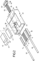
- The optical fiber connector in this embodiment is used for connection of an optical fiber cable with a light receiving element, a light emitting element or an LN (lithium niobate) waveguide, and comprises a
lower ceramics plate 10 having V-grooves 12 provided therein, a holdingceramics plate 30 for holding a plurality of optical fibers of anoptical fiber cable 60 in the V-grooves, respectively, and aresinous socket 20 which is a holder. - The
resinous socket 20 includes acavity 22 capable of accommodating thelower ceramics plate 10, and acavity 24 which communicates at one end with thecavity 22 and is opened at the other end to the outside and which is capable of accommodating a coveringportion 64 of theoptical fiber cable 60. Theresinous socket 20 is provided with a firstadhesive injecting port 21 communicating with opposite side surfaces of thecavity 22, and a secondadhesive injecting port 28 communicating with an upper portion of thecavity 22. - In the optical fiber connector constructed in this manner, the
lower ceramics plate 10 is inserted into thecavity 22 in theresinous socket 20 and then, theoptical fiber cable 60 is inserted from the rearward of thecavity 24, so that theoptical fibers 62 are inserted into the V-grooves 12 in thelower ceramics plate 10, and the coveringportion 64 for theoptical fiber cable 60 is inserted into thecavity 24. then, the holdingplate 30 is placed onto theoptical fibers 62, thereby supporting each of theoptical fibers 62 at three points by both of the holdingplate 30 and the opposite side surfaces of the V-groove 12. In this condition, an adhesive is supplied through the first and secondadhesive injecting ports portion 64 within thecavity 24, while at the same time, securing theoptical fibers 62 in the V-grooves 12. - Also in this embodiment, the
lower ceramics plate 10 having the V-grooves 12 provided therein and the holdingplate 30 are formed from ceramics, and thecavity 24 for accommodating the coveringportion 64 of theoptical fiber cable 60 is provided in theresinous socket 20. Therefore, it is possible to reduce the machining cost for the optical fiber connector. Moreover, since the first and secondadhesive injecting ports resinous socket 20, it is possible to smoothly fill the adhesive into a desired portion, thereby firmly securing the optical fiber connector and theoptical fiber cable 60. - It should be noted that the
resinous socket 20 has been used as a holder in the above-described first to seventh embodiments, but can be replaced by a metal socket. The metal socket is less influenced by an environment in which it is used, and especially, the use of the metal socket makes it possible to avoid the pollution due to the generation of a gas or the like.
and wherein the first cavity has a connection portion proximate to an inner end of the second cavity, which connects the first and second cavities to provides a through passage for the fibers.
Claims (10)
- An optical fiber connector for a plurality of covered optical fibers, comprising:(a) a lower ceramics plate with a top plane surface having a plurality of V-grooves, each groove for respectively holding one fiber;(b) an upper plate, in spaced apart combination with said lower plate, for firmly holding the optical fibers in said lower plate grooves; and(c) a holder having two opposed end portions in which:and wherein said first cavity has a connection portion proximate to an inner end of said second cavity, which connects said first and second cavities to provide a through passage for the fibers.(i) a first cavity is profiled in the first end portion to accommodate the combination of said upper and lower plates; and(ii) a second cavity is profiled in the second end portion to accommodate the covered fibers,
- A connector according to claim 1, further comprising narrowing means disposed in said connection portion above said lower plate, for narrowing the cross section of the connection portion, whereby the fibers are loosely held in place in said grooves.
- A connector according to claim 1, wherein said narrowing means comprises a portion of said lower plate grooves and an upper holding means disposed thereabove by a distance less than the diameter of the optical fiber, so as to narrow the cross-sectional area of said connection portion.
- A connector according to claim 3, wherein said upper holding means is made of ceramics and said first cavity is profiled to also accommodate said upper holding means.
- A connector according to claim 3, wherein said upper holding means is monolithically integral with said holder.
- A connector according to claims 2, 3, 4 or 5, wherein said upper holding means is displaced away from said second cavity so as to narrow the cross-section of said connection portion at a position away from said second cavity and to facilitate the introduction of the fibers through said second cavity.
- A connector according to claims 1, 2, 3, 4 , 5 or 6, wherein said upper plate is made of ceramics.
- A connector according to claims 1, 2, 3, 4 , 5, 6 or 7, wherein said holder is made of resin.
- A connector according to claims 1, 2, 3, 4 , 5, 6 or 7, wherein said holder is made of metal.
- A connector according to claims 1, 2, 3, 4 , 5, 6, 7, 8 or 9, further comprising alignment means having:(i) an alignment pin;(ii) an alignment plate;(iii) two complementary grooves, one profiled in said alignment plate and the other profiled in said top plane surface of said lower plate, so that in combination, said alignment plate and said lower plate firmly hold said alignment pin within said alignment grooves, and wherein said first cavity is profiled to accommodate said alignment means so that said alignment pin is firmly held in place.
Applications Claiming Priority (9)
| Application Number | Priority Date | Filing Date | Title |
|---|---|---|---|
| JP17752/92 | 1992-03-30 | ||
| JP7414992 | 1992-03-30 | ||
| JP1775192U JP2563252Y2 (en) | 1992-03-30 | 1992-03-30 | Optical connector |
| JP1775292 | 1992-03-30 | ||
| JP07414992A JP3277941B2 (en) | 1992-03-30 | 1992-03-30 | Fixing structure for multi-core optical fiber and manufacturing method thereof |
| JP17751/92 | 1992-03-30 | ||
| JP1775192 | 1992-03-30 | ||
| JP74149/92 | 1992-03-30 | ||
| JP1775292U JP2563253Y2 (en) | 1992-03-30 | 1992-03-30 | Optical connector |
Publications (3)
| Publication Number | Publication Date |
|---|---|
| EP0564207A2 true EP0564207A2 (en) | 1993-10-06 |
| EP0564207A3 EP0564207A3 (en) | 1994-04-20 |
| EP0564207B1 EP0564207B1 (en) | 2001-12-05 |
Family
ID=27281957
Family Applications (1)
| Application Number | Title | Priority Date | Filing Date |
|---|---|---|---|
| EP93302419A Expired - Lifetime EP0564207B1 (en) | 1992-03-30 | 1993-03-29 | Optical fiber connector |
Country Status (3)
| Country | Link |
|---|---|
| US (1) | US5315678A (en) |
| EP (1) | EP0564207B1 (en) |
| DE (1) | DE69331248T2 (en) |
Cited By (7)
| Publication number | Priority date | Publication date | Assignee | Title |
|---|---|---|---|---|
| EP0694796A1 (en) * | 1994-07-28 | 1996-01-31 | Ngk Insulators, Ltd. | Method of fixing optical fiber array to substrate |
| US5790733A (en) * | 1996-06-07 | 1998-08-04 | Minnesota Mining And Manufactouring Company | Optoelectronic device receptacle and method of making same |
| EP0943941A1 (en) * | 1998-03-19 | 1999-09-22 | Ngk Insulators, Ltd. | Optical fiber array and production method thereof |
| EP0953855A2 (en) * | 1998-04-30 | 1999-11-03 | Lucent Technologies Inc. | Alignment adapter for an optical connector and method for making same |
| GB2359901A (en) * | 2000-03-01 | 2001-09-05 | Nippon Sheet Glass Co Ltd | Aligning optical fibres and rod lenses |
| FR2823859A1 (en) * | 2001-04-19 | 2002-10-25 | Teem Photonics | Support for positioning and holding of optical fibers comprises first part for holding non-stripped part of fiber and second part for holding stripped part of fiber for connection to optical device |
| US11226464B2 (en) * | 2019-03-07 | 2022-01-18 | Commscope Technologies Llc | Telecommunications fan-out arrangement |
Families Citing this family (44)
| Publication number | Priority date | Publication date | Assignee | Title |
|---|---|---|---|---|
| EP0860721B1 (en) * | 1993-03-31 | 2002-06-26 | Sumitomo Electric Industries, Ltd. | Optical fiber array and method of manufacturing |
| US5394495A (en) * | 1994-02-22 | 1995-02-28 | E. I. Du Pont De Nemours And Company | Optical waveguide connectors and methods of making same |
| FR2716981B1 (en) * | 1994-03-03 | 1996-05-24 | Daniel Boscher | Multichannel optical connection method for optical fibers. |
| US5664039A (en) * | 1994-06-08 | 1997-09-02 | The Whitaker Corporation | High density fiber ferrules and connectors |
| US5633968A (en) * | 1994-07-18 | 1997-05-27 | Sheem; Sang K. | Face-lock interconnection means for optical fibers and other optical components and manufacturing methods of the same |
| US5550942A (en) * | 1994-07-18 | 1996-08-27 | Sheem; Sang K. | Micromachined holes for optical fiber connection |
| US5519798A (en) * | 1994-08-15 | 1996-05-21 | At&T Corp. | Optical fiber connector including V-groove/pin alignment means |
| SE514116C2 (en) * | 1994-10-19 | 2001-01-08 | Ericsson Telefon Ab L M | Process for producing a nested optocomponent, mold for encapsulating an optocomponent and molding device |
| US5604830A (en) * | 1994-12-22 | 1997-02-18 | Hoechst Celanese Corp. | Multiple fiber connector for injection molded multiple fiberoptic coupler unit and cladding for same |
| US5598494A (en) * | 1995-10-23 | 1997-01-28 | The United States Of America As Represented By The Secretary Of The Army | Multi-channel fiber optic connector |
| US5737463A (en) * | 1995-12-22 | 1998-04-07 | Weiss; Roger E. | Massive parallel optical interconnect system |
| US6045270A (en) | 1995-12-22 | 2000-04-04 | Methode Electronics, Inc. | Massive parallel optical interconnect system |
| US6318902B1 (en) | 1996-03-12 | 2001-11-20 | 3M Innovative Properties Company | Optical connector assembly using partial large diameter alignment features |
| US6805493B2 (en) | 1996-03-12 | 2004-10-19 | 3M Innovative Properties Company | Optical connector assembly using partial large diameter alignment features |
| US5778123A (en) * | 1996-03-12 | 1998-07-07 | Minnesota Mining And Manufacturing Company | Alignment assembly for multifiber or single fiber optical cable connector |
| US5907651A (en) * | 1997-07-28 | 1999-05-25 | Molex Incorporated | Fiber optic connector ferrule |
| US5963691A (en) * | 1997-07-28 | 1999-10-05 | Molex Incorporated | Alignment system in a connector ferrule for a fiber optic cable |
| US5867620A (en) * | 1997-07-28 | 1999-02-02 | Molex Incorporated | Fixture for fabricating a fiber optic connector ferrule |
| US5923803A (en) * | 1997-07-28 | 1999-07-13 | Molex Incorporated | Method of fabricating a fiber optic connector ferrule |
| JP4287595B2 (en) * | 1998-07-02 | 2009-07-01 | ティーワイシーオー エレクトロニクス ロジスティック エイジー | Ferrules for pluggable optical connections |
| DE19843164C2 (en) * | 1998-09-21 | 2000-11-23 | Harting Elektrooptische Bauteile Gmbh & Co Kg | Plug part for an optical plug connection |
| KR20000050765A (en) * | 1999-01-14 | 2000-08-05 | 윤종용 | Optical fiber array connector and manufacturing method thereof |
| US6350062B2 (en) * | 1999-05-07 | 2002-02-26 | Corning Cable Systems Llc | Multifiber ferrule defining alignment holes having a tapered lead-in portion |
| US6328479B1 (en) * | 1999-05-24 | 2001-12-11 | Stratos Lightwave, Inc. | Multi-terminator optical interconnect system |
| US6352372B1 (en) * | 1999-10-11 | 2002-03-05 | Lucent Technologies Inc. | High-density optical connectors |
| US6386767B1 (en) * | 1999-12-30 | 2002-05-14 | Fci Americas Technology, Inc. | High density multiple chip fiber array connector |
| US6474878B1 (en) | 2000-03-28 | 2002-11-05 | Berg Technology, Inc. | Optical connector |
| US6798968B2 (en) * | 2000-09-21 | 2004-09-28 | Shipley Company, L.L.C. | Fiber array with support post |
| US20020176670A1 (en) * | 2001-05-10 | 2002-11-28 | Masao Shinoda | Connector ferrule for connecting optical fibers |
| US6695488B2 (en) | 2001-07-19 | 2004-02-24 | Cinch Connectors, Inc. | Tool and method for forming a multi fiber ferrule |
| US6873770B2 (en) * | 2002-01-14 | 2005-03-29 | Photonics Manufacturing Service Ltd. | Optical fiber array |
| US6769811B2 (en) * | 2002-09-03 | 2004-08-03 | Stratos International, Inc. | Multi-fiber optic device |
| US6676299B1 (en) | 2002-11-08 | 2004-01-13 | Stratos Lightwave, Inc. | Device having multiple optical fibers |
| CN101819300B (en) * | 2010-04-16 | 2011-08-31 | 中国人民解放军国防科学技术大学 | Ultrathin connector in high-speed optical interconnection platform |
| CN102243342B (en) * | 2010-05-12 | 2014-03-26 | 鸿富锦精密工业(深圳)有限公司 | Fixing device |
| US8636424B2 (en) | 2010-10-22 | 2014-01-28 | Panduit Corp. | Optical communication connector |
| US11493701B2 (en) | 2010-10-22 | 2022-11-08 | Panduit Corp. | Optical communications connectors |
| US8231283B2 (en) | 2010-12-06 | 2012-07-31 | Hon Hai Precision Ind. Co., Ltd. | Waveguide connector with improved structure for positioning waveguide into ferrule |
| US9874704B2 (en) * | 2014-08-13 | 2018-01-23 | Finisar Corporation | Ferrule assemblies |
| WO2016082100A1 (en) * | 2014-11-25 | 2016-06-02 | 深圳日海通讯技术股份有限公司 | Optical fibre connector plug and assembly method therefor |
| JP2016142951A (en) * | 2015-02-03 | 2016-08-08 | 富士通コンポーネント株式会社 | Optical connector |
| CN108139547B (en) * | 2015-10-12 | 2020-09-08 | 3M创新有限公司 | Optical waveguide positioning features in a multi-waveguide connector |
| US11747577B2 (en) * | 2019-05-22 | 2023-09-05 | Nippon Telegraph And Telephone Corporation | Waveguide connection structure, waveguide chip, connector, and method of manufacturing waveguide connection component, and waveguide connecting method |
| CN111552035A (en) * | 2020-05-21 | 2020-08-18 | 武汉驿路通科技股份有限公司 | High-precision MT (MT) ferrule and manufacturing method thereof |
Citations (4)
| Publication number | Priority date | Publication date | Assignee | Title |
|---|---|---|---|---|
| EP0241724A2 (en) * | 1986-03-14 | 1987-10-21 | Sumitomo Electric Industries Limited | Optical connector and splicer |
| EP0324272A2 (en) * | 1987-12-25 | 1989-07-19 | Seiko Instruments Inc. | Connector for optical fiber ribbon and a method of attaching the same |
| US4973127A (en) * | 1989-05-31 | 1990-11-27 | At&T Bell Laboratories | Multifiber optical connector and method of making same |
| US4998796A (en) * | 1990-02-27 | 1991-03-12 | At&T Bell Laboratories | Method of assembling multi-grooved silicon chip fiber optic terminations |
Family Cites Families (5)
| Publication number | Priority date | Publication date | Assignee | Title |
|---|---|---|---|---|
| US4818058B1 (en) * | 1988-03-03 | 1995-04-25 | Bell Telephone Labor Inc | Optical connector. |
| JPH0361916A (en) * | 1989-07-28 | 1991-03-18 | Tokyo Electric Power Co Inc:The | Multi optical fiber connector |
| JPH0386308A (en) * | 1989-08-31 | 1991-04-11 | Kawasaki Steel Corp | Method for measuring mill constant of edge rolling mill for shape steel |
| JPH03179405A (en) * | 1989-12-08 | 1991-08-05 | Fujikura Ltd | Ferrule for multi-fiber optical connector and metallic mold for production thereof and production of ferrule |
| JP2752773B2 (en) * | 1990-05-25 | 1998-05-18 | 日本碍子株式会社 | Light switch |
-
1993
- 1993-03-25 US US08/037,007 patent/US5315678A/en not_active Expired - Lifetime
- 1993-03-29 EP EP93302419A patent/EP0564207B1/en not_active Expired - Lifetime
- 1993-03-29 DE DE69331248T patent/DE69331248T2/en not_active Expired - Fee Related
Patent Citations (4)
| Publication number | Priority date | Publication date | Assignee | Title |
|---|---|---|---|---|
| EP0241724A2 (en) * | 1986-03-14 | 1987-10-21 | Sumitomo Electric Industries Limited | Optical connector and splicer |
| EP0324272A2 (en) * | 1987-12-25 | 1989-07-19 | Seiko Instruments Inc. | Connector for optical fiber ribbon and a method of attaching the same |
| US4973127A (en) * | 1989-05-31 | 1990-11-27 | At&T Bell Laboratories | Multifiber optical connector and method of making same |
| US4998796A (en) * | 1990-02-27 | 1991-03-12 | At&T Bell Laboratories | Method of assembling multi-grooved silicon chip fiber optic terminations |
Cited By (12)
| Publication number | Priority date | Publication date | Assignee | Title |
|---|---|---|---|---|
| EP0694796A1 (en) * | 1994-07-28 | 1996-01-31 | Ngk Insulators, Ltd. | Method of fixing optical fiber array to substrate |
| US5656120A (en) * | 1994-07-28 | 1997-08-12 | Ngk Insulators, Ltd. | Method of fixing optical fiber array to substrate |
| US5790733A (en) * | 1996-06-07 | 1998-08-04 | Minnesota Mining And Manufactouring Company | Optoelectronic device receptacle and method of making same |
| EP0943941A1 (en) * | 1998-03-19 | 1999-09-22 | Ngk Insulators, Ltd. | Optical fiber array and production method thereof |
| US6304708B1 (en) | 1998-03-19 | 2001-10-16 | Ngk Insulators, Ltd. | Optical fiber array and production method thereof |
| EP0953855A2 (en) * | 1998-04-30 | 1999-11-03 | Lucent Technologies Inc. | Alignment adapter for an optical connector and method for making same |
| EP0953855A3 (en) * | 1998-04-30 | 2004-03-31 | Lucent Technologies Inc. | Alignment adapter for an optical connector and method for making same |
| GB2359901A (en) * | 2000-03-01 | 2001-09-05 | Nippon Sheet Glass Co Ltd | Aligning optical fibres and rod lenses |
| GB2359901B (en) * | 2000-03-01 | 2003-12-17 | Nippon Sheet Glass Co Ltd | Optical fiber-lens array |
| US6823109B2 (en) | 2000-03-01 | 2004-11-23 | Nippon Sheet Glass, Co., Ltd. | Optical fiber-lens array |
| FR2823859A1 (en) * | 2001-04-19 | 2002-10-25 | Teem Photonics | Support for positioning and holding of optical fibers comprises first part for holding non-stripped part of fiber and second part for holding stripped part of fiber for connection to optical device |
| US11226464B2 (en) * | 2019-03-07 | 2022-01-18 | Commscope Technologies Llc | Telecommunications fan-out arrangement |
Also Published As
| Publication number | Publication date |
|---|---|
| EP0564207B1 (en) | 2001-12-05 |
| EP0564207A3 (en) | 1994-04-20 |
| DE69331248T2 (en) | 2002-08-14 |
| DE69331248D1 (en) | 2002-01-17 |
| US5315678A (en) | 1994-05-24 |
Similar Documents
| Publication | Publication Date | Title |
|---|---|---|
| US5315678A (en) | Optical fiber connector | |
| US6986608B2 (en) | Passive alignment connection for fiber optics | |
| KR100289478B1 (en) | Fixture for assembling fiber optic connector ferrules | |
| US5379360A (en) | Optical fiber connector and method of manufacturing the same | |
| US6409394B1 (en) | Optical connector | |
| US20060245695A1 (en) | Multifiber optical connector | |
| CN108139547A (en) | Optical waveguide locating feature in more waveguide connectors | |
| EP1816497B1 (en) | Optical connector and method for manufacturing the same | |
| US4564260A (en) | Optical waveguide branching unit and method of making same | |
| US6767136B1 (en) | Device having multiple optical fibers | |
| KR100323007B1 (en) | Fiber optic connecter ferrule | |
| KR100289477B1 (en) | Alignment system in connector ferrules for fiber optic cables | |
| US20010001623A1 (en) | Optical fiber splice device | |
| ITMI940594A1 (en) | INTERCONNECTION ELEMENT FOR MULTIFIBER CABLES | |
| EP0277390B1 (en) | Assembly comprising a planar optical circuit and an optical fibre coupled thereto | |
| JPH0659161A (en) | Pitch change connector for multiple optical fiber | |
| JP3273603B2 (en) | Fixing structure for multi-core optical fiber and manufacturing method | |
| JP3543319B2 (en) | Ferrule for optical connector | |
| JPH1184161A (en) | Optical connector | |
| JP2593535B2 (en) | Plastic ferrule for multi-core optical connector | |
| JPS61138214A (en) | Terminal tool for arraying optical fiber | |
| JP3277941B2 (en) | Fixing structure for multi-core optical fiber and manufacturing method thereof | |
| JP2000214348A (en) | Optical connector ferule and optical connector | |
| JPH11248965A (en) | Optical connector | |
| JPH0431562B2 (en) |
Legal Events
| Date | Code | Title | Description |
|---|---|---|---|
| PUAI | Public reference made under article 153(3) epc to a published international application that has entered the european phase |
Free format text: ORIGINAL CODE: 0009012 |
|
| AK | Designated contracting states |
Kind code of ref document: A2 Designated state(s): DE FR GB |
|
| PUAL | Search report despatched |
Free format text: ORIGINAL CODE: 0009013 |
|
| AK | Designated contracting states |
Kind code of ref document: A3 Designated state(s): DE FR GB |
|
| 17P | Request for examination filed |
Effective date: 19940909 |
|
| 17Q | First examination report despatched |
Effective date: 19960222 |
|
| GRAG | Despatch of communication of intention to grant |
Free format text: ORIGINAL CODE: EPIDOS AGRA |
|
| GRAG | Despatch of communication of intention to grant |
Free format text: ORIGINAL CODE: EPIDOS AGRA |
|
| GRAH | Despatch of communication of intention to grant a patent |
Free format text: ORIGINAL CODE: EPIDOS IGRA |
|
| GRAG | Despatch of communication of intention to grant |
Free format text: ORIGINAL CODE: EPIDOS AGRA |
|
| GRAH | Despatch of communication of intention to grant a patent |
Free format text: ORIGINAL CODE: EPIDOS IGRA |
|
| GRAH | Despatch of communication of intention to grant a patent |
Free format text: ORIGINAL CODE: EPIDOS IGRA |
|
| GRAA | (expected) grant |
Free format text: ORIGINAL CODE: 0009210 |
|
| AK | Designated contracting states |
Kind code of ref document: B1 Designated state(s): DE FR GB |
|
| REG | Reference to a national code |
Ref country code: GB Ref legal event code: IF02 |
|
| REF | Corresponds to: |
Ref document number: 69331248 Country of ref document: DE Date of ref document: 20020117 |
|
| ET | Fr: translation filed | ||
| PLBE | No opposition filed within time limit |
Free format text: ORIGINAL CODE: 0009261 |
|
| STAA | Information on the status of an ep patent application or granted ep patent |
Free format text: STATUS: NO OPPOSITION FILED WITHIN TIME LIMIT |
|
| 26N | No opposition filed | ||
| PGFP | Annual fee paid to national office [announced via postgrant information from national office to epo] |
Ref country code: GB Payment date: 20030319 Year of fee payment: 11 |
|
| PGFP | Annual fee paid to national office [announced via postgrant information from national office to epo] |
Ref country code: FR Payment date: 20030321 Year of fee payment: 11 |
|
| PGFP | Annual fee paid to national office [announced via postgrant information from national office to epo] |
Ref country code: DE Payment date: 20030326 Year of fee payment: 11 |
|
| PG25 | Lapsed in a contracting state [announced via postgrant information from national office to epo] |
Ref country code: GB Free format text: LAPSE BECAUSE OF NON-PAYMENT OF DUE FEES Effective date: 20040329 |
|
| PG25 | Lapsed in a contracting state [announced via postgrant information from national office to epo] |
Ref country code: DE Free format text: LAPSE BECAUSE OF NON-PAYMENT OF DUE FEES Effective date: 20041001 |
|
| GBPC | Gb: european patent ceased through non-payment of renewal fee |
Effective date: 20040329 |
|
| PG25 | Lapsed in a contracting state [announced via postgrant information from national office to epo] |
Ref country code: FR Free format text: LAPSE BECAUSE OF NON-PAYMENT OF DUE FEES Effective date: 20041130 |
|
| REG | Reference to a national code |
Ref country code: FR Ref legal event code: ST |