EP0565253A2 - Apparatus and method for processing payment for a merchandise item - Google Patents
Apparatus and method for processing payment for a merchandise item Download PDFInfo
- Publication number
- EP0565253A2 EP0565253A2 EP93302089A EP93302089A EP0565253A2 EP 0565253 A2 EP0565253 A2 EP 0565253A2 EP 93302089 A EP93302089 A EP 93302089A EP 93302089 A EP93302089 A EP 93302089A EP 0565253 A2 EP0565253 A2 EP 0565253A2
- Authority
- EP
- European Patent Office
- Prior art keywords
- item
- amount
- payment
- denominations
- block
- Prior art date
- Legal status (The legal status is an assumption and is not a legal conclusion. Google has not performed a legal analysis and makes no representation as to the accuracy of the status listed.)
- Granted
Links
Images


Classifications
-
- G—PHYSICS
- G07—CHECKING-DEVICES
- G07G—REGISTERING THE RECEIPT OF CASH, VALUABLES, OR TOKENS
- G07G1/00—Cash registers
- G07G1/12—Cash registers electronically operated
-
- G—PHYSICS
- G06—COMPUTING; CALCULATING OR COUNTING
- G06F—ELECTRIC DIGITAL DATA PROCESSING
- G06F3/00—Input arrangements for transferring data to be processed into a form capable of being handled by the computer; Output arrangements for transferring data from processing unit to output unit, e.g. interface arrangements
- G06F3/01—Input arrangements or combined input and output arrangements for interaction between user and computer
- G06F3/048—Interaction techniques based on graphical user interfaces [GUI]
- G06F3/0487—Interaction techniques based on graphical user interfaces [GUI] using specific features provided by the input device, e.g. functions controlled by the rotation of a mouse with dual sensing arrangements, or of the nature of the input device, e.g. tap gestures based on pressure sensed by a digitiser
- G06F3/0488—Interaction techniques based on graphical user interfaces [GUI] using specific features provided by the input device, e.g. functions controlled by the rotation of a mouse with dual sensing arrangements, or of the nature of the input device, e.g. tap gestures based on pressure sensed by a digitiser using a touch-screen or digitiser, e.g. input of commands through traced gestures
-
- G—PHYSICS
- G06—COMPUTING; CALCULATING OR COUNTING
- G06Q—INFORMATION AND COMMUNICATION TECHNOLOGY [ICT] SPECIALLY ADAPTED FOR ADMINISTRATIVE, COMMERCIAL, FINANCIAL, MANAGERIAL OR SUPERVISORY PURPOSES; SYSTEMS OR METHODS SPECIALLY ADAPTED FOR ADMINISTRATIVE, COMMERCIAL, FINANCIAL, MANAGERIAL OR SUPERVISORY PURPOSES, NOT OTHERWISE PROVIDED FOR
- G06Q20/00—Payment architectures, schemes or protocols
- G06Q20/08—Payment architectures
- G06Q20/20—Point-of-sale [POS] network systems
-
- G—PHYSICS
- G07—CHECKING-DEVICES
- G07G—REGISTERING THE RECEIPT OF CASH, VALUABLES, OR TOKENS
- G07G1/00—Cash registers
- G07G1/01—Details for indicating
Definitions
- the present invention relates to an apparatus and method for processing payment for a merchandise item.
- Known point of sale terminal devices include a touch screen, the use of which transfers the function of the keyboard to designated portions of the touch screen.
- electronic receipts have been employed which display a list of the items ordered together with functional elements for manipulating the items listed in the receipt.
- functional elements for manipulating the items listed in the receipt.
- interface objects or controls keys, buttons, knobs, etc.
- these interface objects or controls take up space and are usually laid out close to one another so as to keep most in one location.
- designers have grouped related buttons, used color coding, etc.
- the size of the typical receipt item is small thereby precluding the use of the human finger as a means to modify the item.
- the total amount of the purchased items is displayed on the touch screen and identified as the payment due by the customer for the purchase of the merchandise items.
- the customer will present a currency bill whose denomination is larger than the amount due requiring the operator to enter the payment received from the customer into the terminal device.
- the amount of change due the customer is then displayed requiring the operator to retrieve from the cash drawer located in the data terminal device the number of bills and coins which constitute such change. It is during this payment operation that most of the errors associated with checkout operations are found.
- apparatus for processing the payment for at least one purchased merchandise item comprising display means for displaying the amount due for the purchase of said at least one item, characterized in that said display means is arranged to display a plurality of payment amounts that may be tendered by the customer as payment for said at least one item having regard to the amount due, and in that there are provided means arranged to calculate the amount of change in response to the selection of one of the displayed amounts corresponding to the amount tendered.
- the invention provides means for displaying the payment tendered and the change due, which reduces the number of keystrokes required by the operator in processing the payment of the items purchased by the customer.
- a method of processing the payment for at least one purchased merchandise item comprising displaying the amount due for the purchase of said at least one item, characterized by the steps of storing a listing of all the currency denominations available for said payment, dividing said amount due by each currency denomination, adding one to the quotient whenever a remainder is generated as a result of the division, multiplying said denominations by the respective quotient plus one values obtained for each denomination, displaying the products obtained by the multiplication as possible payment amounts that may be tendered by a customer and calculating the amount of change due in response to selection of one of said displayed amounts corresponding to the amount tendered.
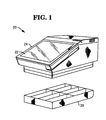
- a perspective view of the data terminal device 20 which includes a touch screen panel 22 mounted in a top surface 24 of the terminal device 20, and a cash till 26 which may be secured to the bottom portion of the terminal device 20 or may be remotely positioned adjacent the terminal device.
- a block diagram of the touch screen panel 22 which includes a panel detector unit 34 which senses the location of the operator's finger on the panel 22 and generates electrical signals to represent such location for transmission to a control unit 36 which decodes electrical signals for actuating the panel to display information in a manner that will be described more fully hereinafter.
- the control unit 36 in response to receiving the electrical signals from the panel detector unit 34, will output control signals to a panel control unit 38 which controls the panel to generate a number of displays for processing the purchased items.
- One of these displays is the electronic receipt40 (Figs. 3-11 inclusive) which may list the items ordered by the customer together with the price of the items or any other type of desired information.
- the control unit 36 may also operate a speaker 42 to generate tone signals representing a successful completion of the reading of the touch screen panel 22 by the control unit 36.
- FIG. 3 shows an electronic receipt in which the items 42 are listed together with their prices 43.
- an item separator such as the dotted lines 44 (Fig. 4) can help to distinguish one item from another item.
- a finger to select one of the items 42 for the modification would be difficult since the items are so narrowthat positioning a finger over one of the items would overlap adjacent items.
- the present invention provides a pair of scroll buttons 46, 48 (Figs.
- the operator may normally be required to press an "item void” key followed by the "large” key and then "fries” keys on the keyboard of a terminal device.
- This method of modifying an item followed by an item specification can lead to more trouble especially if a particular item needs more than one modification.
- the buttons 46 and 48 By utilizing the buttons 46 and 48, the number of keystrokes is reduced thereby increasing the speed of the modification operation.
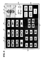
- a diagra- matic representation of a display 55 on the touch screen panel 22 which includes a plurality of multiple function buttons 56, single function buttons 58, transaction buttons or keys 60 and an electronic receipt40.
- the electronic receipt 40 includes the balance due 62 for the items ordered. Touching the arrow portion 61 of the multi-function button 56 representing HAMBURGER will result in bringing up the display 63 (Fig. 10) on the panel 22 displaying condiments buttons 65 which may be touched to complete the order.
- Figs. 11A-11H there is illustrated the operation of the present invention in the generation and the moving of the highlight bar 52 through the receipt 40 as a result of touching the scroll buttons 46, 48.
- the application software for the terminal 20 may provide for use of the highlight bar 52 for the receipt as an option.
- Figs. 11Aand 11 B an item will not be highlighted until it is added to the receipt list.
- Touching the scroll button 46 will move the highlight bar 52 in an upward direction to highlight items 3-5 (Figs 11 C-11 E) until it reaches the top of the receipt at which time items listed above ITEM1 in the receipt 40 can move in a downward direction through the highlight bar 52.
- the position of the highlight bar will change to highlight the last item added or inserted (Figs. 11E-11H).
- FIG. 12 there is disclosed a block diagram of the control unit 36 (Fig. 2) which includes a microprocessor 170, a memory 172, a denomination counter 174, a button counter 176, a TEMP 1 counter 178 and a TEMP 2 counter 180 which are used in the change due operation using the touch screen panel 22 as will be described more fully hereinafter.
- a microprocessor 170 Used with the counters 174-180 are tables 182 (Fig. 13A) and 183 (Fig. 13B) which are stored in the memory 172 and controlled by the microprocessor 170.
- the table 182 includes a column 184 listing all of the currency denominations available for an amount tendering operation while column 184 of table 183 lists all of the currency denominations available for change due operations.
- Both tables include a corresponding column 186 containing reference numerals identifying corresponding currency denominations used in determining the type of currency which is to make up the customer's payment options and change as will be described more fully hereinafter.
- the output count of the counter 174 corresponds to the reference numerals listed in column 186 and represent the corresponding currency denomination.
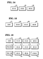
- Figs. 14-16 there are shown displays on the touch screen panel 22 which may occur during the tendering portion of a checkout operation in which the customer will present currency as payment for the amount due for the purchased items.
- the displays shown in Figs. 14-16 are based on the premise that most customers will pay for the amount due using one or more of the common denomination bills (1, 5, 10, 20). For example, if the balance due were $14.49, the most likely payments would be any one of a combination of one dollar bills, five dollar bills and/or ten dollar bills or even a twenty dollar bill. Therefore based on the amount due, the present invention generates displays which offer logical and likely payment options. Thus for the example shown in Fig. 14, the first display box or button 64 will display the exact amount due ($14.49).
- the one dollar denomination used to calculate the first factor of one greater than the amount due is used to dynamically label the second display button 66.
- the five dollar denomination is used to calculate the first factor of five greater than the amount due. This amount, also fifteen dollars, has already been listed and will not be listed again.
- the ten dollar denomination is used to calculate the first factor of ten greater than the amount due. This amount (twenty dollars) is used to dynamically label the button 68. It will be seen from this arrangement that the number of keystrokes required of the operator to generate the amount due from the customer as a result of tendering one of the bills displayed in the display buttons 66 and 68 is held to a minimum. Otherwise the operator would have to use the keys on a numeric keyboard associated with the terminal device requiring the actuation of the 2 and the 0 keys together with the subtraction key and the keys representing the amount due for the purchase of the merchandise items.
- buttons in Fig. 14 illustrating that cash is the payment method.
- Fig. 16 illustrates other types of payment methods that may be displayed.
- the buttons associated with the button 72 will be actuated by the operator.
- the button 78 will be actuated by the operator. It will be seen from Fig. 16 that the buttons located on the screen will cover most of the types of payments by the customer that can occur. If the balance due was $14.49 and the customer pays with a twenty dollar bill, the operator, by touching the button 68, has specified the payment amount together with the payment method as well.
- buttons 80-84 representing the amount of the travellers check. It will be seen that by touching one of the buttons 80-84, the amount tendered and the method of payment will be transmitted to the control unit 36 (Fig. 3) for use in determining the change due to the customer.
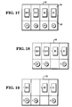
- the display 90 represents the outline of the cash till 26 (Fig. 1) showing images of the particular coin compartments 92 and the bill compartments 94 with the designated value of the coins and bills which are to be found in each of the compartments.
- the display 90 will appear as the display 98 (Fig. 18) showing the location and the specific number of the coins and bills which are to be distributed to the customer as the change for the amount submitted by the customer. If a specific bill or coin associated with one of the compartments 92 and 94 in the cash till 26 (Fig.
- the displays 90, 98 and 100 are dynamically changed in accordance with the type of payment selected by the customer and the currency available for dispensing as change and that the operator's task has been simplified from performing mental running totals to the counting of bills and coins. This simplification can in turn speed up the tendering process and increase transaction throughput.
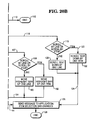
- Figs. 20A and 20B there is disclosed a flow diagram of the operation of the microprocessor 170 (Fig. 12) for controlling the movement of the highlight bar 52 as a result of touching the scroll buttons 46 and 48 (Fig. 7).
- the microprocessor 170 in response to the appearance of an encoded message (block 104) from the panel detector unit 34 (Fig. 3) indicating that the up arrow button 46 (Fig. 11C) has been touched (block 106), will determine if there is more text above the location which can be moved in an upward direction (block 108) and if there isn't, the microprocessor will proceed over line 110 and terminate the operation (block 112) (Fig. 20B).
- the microprocessor will check to see if the highlight bar 52 (Fig. 11 B) is on (block 114) and if it is not on, the microprocessorwill proceed over line 116 and determine if the items in the receipt are to be scrolled ether by line or by item (block 118)(Fig. 20B). If the items are to be scrolled item by item, the microprocessor will proceed over line 120 and scroll the text down by one item (block 122) and then proceed over line 124 to send a message to the application software that the item selection has changed (block 126) and then terminate the operation (block 128). If the scrolling is to be line by line, the microprocessorwill scroll the text down by one line (block 129) and then proceed over line 122 to block 128.
- the microprocessor will determine whether the highlight bar is located at the top, middle, or bottom of the receipt 40 (block 130). If the highlight bar is at the top of the receipt 40 (Fig. 11 B), the microprocessor will proceed over line 132 and determine if the receipt is to be scrolled by line or by item (block 134). If the scrolling is to occur item by item, the microprocessor will proceed over line 136 and scroll down the text in the receipt by one item (block 138) with the highlight bar staying at the top (Fig. 11 B)(block 140) and then proceed over line 144 to block 126 and block 128.
- the microprocessor will scroll down the text by one line (block 146) and then proceed over line 148 to block 140 positioning the highlight bar at the top of the electronic receipt. If the highlight bar is at the middle of the receipt (Fig. 11 E), the microprocessor will determine if the receipt 40 is to be scrolled by line or by item (block 150). If the scrolling is to occur by line, the microprocessor will move the highlight bar up one line (block 152) and proceed over line 154 to block 126. If the text is to be scrolled item by item, the microprocessor will move the highlight bar up one item (block 156) and terminate the operation over line 154 to block 126 and block 128.
- the microprocessor will proceed over line 157 and determine if the scrolling of the text is to be by line or by item (block 158) (Fig. 20B). If the scrolling is to occur by line, the microprocessor will move the highlight bar up one line (block 160) and terminate the operation through blocks 126 and 128. If the scrolling is to occur by item, the microprocessor will move the highlight up one item (block 162) and terminate the operation through blocks 126 and 128. It will be seen from this operation that by touching the up button 46 (Fig. 8), the highlight bar 52 will either move in a vertical direction to highlight one of the items in the receipt or the text will move through the stationary highlight bar depending on the location of the highlight bar. Touching the down arrow 48 (Fig. 11A) results in the opposite movement.
- Fig. 21 there is shown aflowdi- agram of the operation of the microprocessor 170 for determining the type of bills and coins that are to be displayed representing the payment options that the customer may present as payment for the amount due for the purchased merchandise items( Figs. 14-16).
- the microprocessor 170 Fig. 12
- the microprocessor 170 will store in the memory 172 (Fig. 12) a number equal to the number of different bills and coins that are available, will set the denomination counter 174 (Fig.
- the microprocessor will check to see if the value of the denomination counter 174 is equal to zero (block 194). If it is, the microprocessor will generate the button 64 (Figs. 14-16 inclusive) to display the bill denomination as the amount due for the purchased merchandise (block 196). With this arrangement, the button 64 (Figs. 14-16 inclusive) will always be generated to display the amount due. If the denomination counter 174 is not equal to zero, the value of the bill being processed will be set equal to the currency denomination listed in table 186 (Fig.
- the microprocessor will increment the counter by one which represents the next currency denomination that is listed in the table 186 (block 200).
- the microprocessor will then determine what amount will be displayed as the next tendering option. This is accomplished by determining the number of the designated bills that are needed to pay off the amount due. To find this value, the microprocessor divides the value of the bill into the amount due and adds one to this value if the division had a remainder. This operation is represented by the term "AMT DUE MOD BILL" in block 202.
- the microprocessor will set this value in the TEMP 2 counter 179 (Fig. 12) as the amount due (block 204) and check (block 208) to see if this value is greater than the value set in the TEMP 1 counter 178 (Block 188). If there is a remainder which is notequal to zero (block 202), the microprocessor will set a value in the TEMP 2 counter 180 equal to the bill denomination times a value equal to the number of times the bill denomination can be divided into the amount due plus one (block 206). This value is represented by the term "AMT DUE DIV BILL + 1" in block 206.
- the microprocessor will then compare the value in the TEMP 2 counter 180 with the value in the TEMP 1 counter 178 (block 208) and if it is greater, the touch screen panel 22 will display the bill denomination in one of the buttons 66, 68 (Figs. 14-16 inclusive) as one of the bills which may be submitted by the customer as payment for the amount due (block 214). If the value in the TEMP 2 counter is not greater than the value in the TEMP 1 counter, the microprocessor will proceed over the lines 210 and 212 and check to see if the value in the denomination counter 174 is less than the number of currency denominations available and that the number of buttons in the cash till compartments 92 and 94 (Fig. 17) is less than the number of buttons available (block 190). This process is repeated if necessary using the currency denominations listed in Table 182 (Fig. 13A) to provide the payment options shown in Figs. 14-16 inclusive.
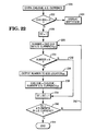
- Fig. 22 there is shown a flow diagram of the operation of the microprocessor for generating the displays shown in Figs. 18 and 19 representing the particular bills and coins constituting the change which is to be given to the customer.
- the microprocessor 170 knowing the amount of change that is due as a result of subtracting the amount due from the bill tendered by the customer and the currency (bills and coins) that is available (block 220), will check to see if the change due is equal to zero (block 222) and if it is not, will generate the display 98 (Fig. 18) with the compartments 92, 94 shown as empty (block 224) which ends the operation.
- the microprocessor will set the denomination counter 174 (Fig. 12) to one (block 226) representing the first currency denomination in column 184 of table 183 (Fig. 13B) which in the present example is twenty.
- the microprocessor will then generate a number representing the change due divided by the currency denomination selected in block 226 (block 228) and check to see if that number is greater than zero (block 230). If the number is not greater than zero, the microprocessor will proceed over line 232 and increment the counter 174 (Fig. 12) by one (block 234) and then determine (block 240) if the new number representing the currency denomination is larger than the number of elements in the denomination column 184 of the Table 183 (Fig. 13B).
- the microprocessor will end the operation (block 244). If it is not larger, the microprocessor will proceed over line 242 and generate a new number as determined in block 228 representing the number of times the value of the currency denomination goes into the change due. If this number (block 230) is greater than zero, the microprocessor will output this number or value to the particular compartment location 92, 94 (Figs. 18 and 19) (block 236)comprising a button representing the specific number of its associated currency denomination which is to be dispensed as part of the change due. The microprocessor will then establish a new change due (block 238) by subtracting from the original change a value representing the amount to be dispensed as found in block 236.
- the microprocessor will then increment the counter 174 (block 234) by one and then proceed to block 240 to determine if the new bill denomination is greater than the available currency elements. If it is not, the microprocessor will proceed over line 242 to block 228 to determine the number of times the new currency denomination goes into the new change due as found in block 238. This sequence is repeated until the display 98 (Fig. 18) is generated.
- the displays 98 (Fig. 18) and 100 (Fig. 19) will display buttons representing the particular bill and coin denominations that are available and the number of such denominations which constitute the change due to the customer, utilizing the minimum amount of keystrokes by the checkout operator to accomplish this result.
Abstract
Description
- The present invention relates to an apparatus and method for processing payment for a merchandise item.
- Known point of sale terminal devices include a touch screen, the use of which transfers the function of the keyboard to designated portions of the touch screen. As part of this new development, electronic receipts have been employed which display a list of the items ordered together with functional elements for manipulating the items listed in the receipt. In order for the operators to use these functional elements, more interface objects have been added to the point of sale devices control panel. These interface objects or controls (keys, buttons, knobs, etc.) take up space and are usually laid out close to one another so as to keep most in one location. Until the operators become familiar with the terminal devices control panel layout, much time is spent searching for the appropriate controls. To reduce this search, designers have grouped related buttons, used color coding, etc. Where an electronic receipt is displayed on the touch screen, the size of the typical receipt item is small thereby precluding the use of the human finger as a means to modify the item. At the end of the checkout operation, the total amount of the purchased items is displayed on the touch screen and identified as the payment due by the customer for the purchase of the merchandise items. In most checkout operations the customer will present a currency bill whose denomination is larger than the amount due requiring the operator to enter the payment received from the customer into the terminal device. Upon actuation of a total key on the terminal device, the amount of change due the customer is then displayed requiring the operator to retrieve from the cash drawer located in the data terminal device the number of bills and coins which constitute such change. It is during this payment operation that most of the errors associated with checkout operations are found.
- It is therefore an object of the present invention to provide an apparatus and method for processing the paymentfora purchased merchandise item which reduces the likelihood of errors occurring.
- According to one aspect of the present invention there is provided apparatus for processing the payment for at least one purchased merchandise item comprising display means for displaying the amount due for the purchase of said at least one item, characterized in that said display means is arranged to display a plurality of payment amounts that may be tendered by the customer as payment for said at least one item having regard to the amount due, and in that there are provided means arranged to calculate the amount of change in response to the selection of one of the displayed amounts corresponding to the amount tendered.
- Advantageously, the invention provides means for displaying the payment tendered and the change due, which reduces the number of keystrokes required by the operator in processing the payment of the items purchased by the customer.
- According to another aspect of the present invention there is provided a method of processing the payment for at least one purchased merchandise item comprising displaying the amount due for the purchase of said at least one item, characterized by the steps of storing a listing of all the currency denominations available for said payment, dividing said amount due by each currency denomination, adding one to the quotient whenever a remainder is generated as a result of the division, multiplying said denominations by the respective quotient plus one values obtained for each denomination, displaying the products obtained by the multiplication as possible payment amounts that may be tendered by a customer and calculating the amount of change due in response to selection of one of said displayed amounts corresponding to the amount tendered.
- An embodiment of the present invention is described further hereinafter, with reference to accompanying drawings in which:
- Fig. 1 is a perspective view of a data terminal device embodying the present invention;
- Fig. 2 is a block diagram of the touch screen associated with the data terminal device of Fig. 1;
- Fig. 3 is a diagrammatic representation of an electronic receipt displayed on the touch screen of Fig. 2;
- Fig. 4 is another diagrammatic representation of an electronic receipt displayed on the touch screen showing single line items separated by a dotted line together with an item which occupies two lines;
- Fig. 5 is yet another diagrammatic representation of a electronic receipt showing one of the items highlighted;
- Fig. 6 is a diagrammatic representation of the electronic receipt of Fig. 4 showing the highlighting of one item;
- Fig. 7 is a diagrammatic representation of the scrolling buttons and the miscellaneous button superimposed on an electronic receipt;
- Fig. 8 is a further diagrammatic representation of an electronic receipt showing the enlargement of a highlighted item generated as a result of touching the miscellaneous button;
- Fig. 9 is a diagrammatic representation of an actuated touch screen display showing the location of the electronic receipt together with buttons including transaction buttons, item ordering buttons and multi-function buttons;
- Fig. 10 is a diagrammatic representation of a touch screen display generated as a result of touching the arrow portion of one of the multi-function buttons of Fig. 9;
- Figs. 11A-11H inclusive are diagrammatic representation of an electronic receipt showing the highlighting and the movement of various items on the receipt as a result of pressing the scroll buttons and the adding of an item to the receipt;
- Fig. 12 is a block diagram of the control unitofFig. 2 which includes counters, a memory and a microprocessor used in the controlling of the touch screen;
- Figs. 13Aand 13B are diagrammatic representations of the table found in the memory of the control unit for listing the currency denominations available to be submitted by the customer as payment for the purchased items and dispensed as change due to the customer;
- Fig. 14 illustrates one form of the buttons displaying a cash payment amountwhich may be submitted by the customer in payment of the amount due;
- Fig. 15 illustrates anotherform of the buttons associated with a touch screen display;
- Fig. 16 illustrates yet another form of the buttons associated with a touch screen display;
- Fig. 17 is an illustration of a touch screen display representing a cash till indicating the location of the specific coin and bill compartments;
- Fig. 18 is an illustration of the display of Fig. 17 after a specific dedicated cash payment has been made by the customer indicating the specific bills and coins which are to be removed from the cash till as the change due the customer;
- Fig. 19 is an illustration of a display similar to Fig. 18 which is generated after it was found that the ten dollar bill displayed in Fig. 18 was not available;
- Fig. 20A and 20B taken together disclose a flow diagram showing the operation of the microprocessor in generating the electronic receipt displays shown in Figs. 11A-11F inclusive;
- Fig. 21 is a flow diagram showing the operation of the microprocessor in generating the tendering option displays shown in Figs. 14-16 inclusive; and
- Fig. 22 is a flow diagram showing the operation of the microprocessor in generating the change due displays shown in Figs 18 and 19.
- Referring now to Fig. 1, there is shown a perspective view of the
data terminal device 20 which includes atouch screen panel 22 mounted in atop surface 24 of theterminal device 20, and a cash till 26 which may be secured to the bottom portion of theterminal device 20 or may be remotely positioned adjacent the terminal device. - Referring now to Fig. 2, there is shown a block diagram of the
touch screen panel 22 which includes apanel detector unit 34 which senses the location of the operator's finger on thepanel 22 and generates electrical signals to represent such location for transmission to acontrol unit 36 which decodes electrical signals for actuating the panel to display information in a manner that will be described more fully hereinafter. Thecontrol unit 36, in response to receiving the electrical signals from thepanel detector unit 34, will output control signals to apanel control unit 38 which controls the panel to generate a number of displays for processing the purchased items. One of these displays is the electronic receipt40 (Figs. 3-11 inclusive) which may list the items ordered by the customer together with the price of the items or any other type of desired information. Thecontrol unit 36 may also operate aspeaker 42 to generate tone signals representing a successful completion of the reading of thetouch screen panel 22 by thecontrol unit 36. - Referring now to Figs. 3-9 inclusive, there are shown diagrammatic representations of the
electronic receipts 40 which may be displayed during an operation of thetouch screen panel 22. Fig. 3 shows an electronic receipt in which theitems 42 are listed together with theirprices 43. When certain items take up more than one line or have several components, an item separator such as the dotted lines 44 (Fig. 4) can help to distinguish one item from another item. Where one of the items is required to be modified or changed, it is obvious that using a finger to select one of theitems 42 for the modification would be difficult since the items are so narrowthat positioning a finger over one of the items would overlap adjacent items. The present invention provides a pair ofscroll buttons 46, 48 (Figs. 7, 9, 10 and 11A-1F inclusive) comprising directional arrows superimposed on the receipt40 which, when touched by the operator, will scroll the contents of the electronic receipt or move a highlight bar 52 (Figs. 11A-11 H inclusive) on the receipt. In order to modify a highlighted item such as enlarging an item (Fig. 8), there is superimposed on the electronic receipt between thescroll buttons scroll buttons buttons - Referring now to Fig. 9 there is shown a diagra- matic representation of a
display 55 on thetouch screen panel 22 which includes a plurality ofmultiple function buttons 56,single function buttons 58, transaction buttons orkeys 60 and an electronic receipt40. As shown, theelectronic receipt 40 includes the balance due 62 for the items ordered. Touching thearrow portion 61 of themulti-function button 56 representing HAMBURGER will result in bringing up the display 63 (Fig. 10) on thepanel 22 displayingcondiments buttons 65 which may be touched to complete the order. - Referring nowto Figs. 11A-11H inclusive, there is illustrated the operation of the present invention in the generation and the moving of the
highlight bar 52 through thereceipt 40 as a result of touching thescroll buttons highlight bar 52 for the receipt as an option. As shown in Figs. 11Aand 11 B, an item will not be highlighted until it is added to the receipt list. Touching thescroll button 46 will move thehighlight bar 52 in an upward direction to highlight items 3-5 (Figs 11 C-11 E) until it reaches the top of the receipt at which time items listed above ITEM1 in thereceipt 40 can move in a downward direction through thehighlight bar 52. As items are added or inserted, the position of the highlight bar will change to highlight the last item added or inserted (Figs. 11E-11H). - Referring now to Fig. 12, there is disclosed a block diagram of the control unit 36 (Fig. 2) which includes a
microprocessor 170, amemory 172, adenomination counter 174, abutton counter 176, aTEMP 1counter 178 and aTEMP 2counter 180 which are used in the change due operation using thetouch screen panel 22 as will be described more fully hereinafter. Used with the counters 174-180 are tables 182 (Fig. 13A) and 183 (Fig. 13B) which are stored in thememory 172 and controlled by themicroprocessor 170. The table 182 includes acolumn 184 listing all of the currency denominations available for an amount tendering operation whilecolumn 184 of table 183 lists all of the currency denominations available for change due operations. Both tables include acorresponding column 186 containing reference numerals identifying corresponding currency denominations used in determining the type of currency which is to make up the customer's payment options and change as will be described more fully hereinafter. The output count of thecounter 174 corresponds to the reference numerals listed incolumn 186 and represent the corresponding currency denomination. - Referring now to Figs. 14-16, there are shown displays on the
touch screen panel 22 which may occur during the tendering portion of a checkout operation in which the customer will present currency as payment for the amount due for the purchased items. The displays shown in Figs. 14-16 are based on the premise that most customers will pay for the amount due using one or more of the common denomination bills (1, 5, 10, 20). For example, if the balance due were $14.49, the most likely payments would be any one of a combination of one dollar bills, five dollar bills and/or ten dollar bills or even a twenty dollar bill. Therefore based on the amount due, the present invention generates displays which offer logical and likely payment options. Thus for the example shown in Fig. 14, the first display box orbutton 64 will display the exact amount due ($14.49). Next comes the one dollar denomination used to calculate the first factor of one greater than the amount due. This amount (fifteen dollars) is used to dynamically label thesecond display button 66. Next the five dollar denomination is used to calculate the first factor of five greater than the amount due. This amount, also fifteen dollars, has already been listed and will not be listed again. Next the ten dollar denomination is used to calculate the first factor of ten greater than the amount due. This amount (twenty dollars) is used to dynamically label thebutton 68. It will be seen from this arrangement that the number of keystrokes required of the operator to generate the amount due from the customer as a result of tendering one of the bills displayed in thedisplay buttons - If a "payment method" specifier is needed to be added, the button 70 (Fig. 15) would be added to the buttons in Fig. 14 illustrating that cash is the payment method. Fig. 16 illustrates other types of payment methods that may be displayed. Thus if an ATM card is presented as payment for the amount due, the buttons associated with the
button 72 will be actuated by the operator. Where a traveller's check is presented for the amount due, thebutton 78 will be actuated by the operator. It will be seen from Fig. 16 that the buttons located on the screen will cover most of the types of payments by the customer that can occur. If the balance due was $14.49 and the customer pays with a twenty dollar bill, the operator, by touching thebutton 68, has specified the payment amount together with the payment method as well. If the customer had paid with his/herATM card and wanted ten dollars back, then the operator would touch thebutton 76. In a similar manner, the use of a travellers check would result in the touching of thetouch screen panel 22 adjacent the specific buttons 80-84 representing the amount of the travellers check. It will be seen that by touching one of the buttons 80-84, the amount tendered and the method of payment will be transmitted to the control unit 36 (Fig. 3) for use in determining the change due to the customer. - Referring now to Fig. 17, there is shown the
display 90 which occurs at the same time the displays of Fig. 14-16 occur. Thedisplay 90 represents the outline of the cash till 26 (Fig. 1) showing images of the particular coin compartments 92 and the bill compartments 94 with the designated value of the coins and bills which are to be found in each of the compartments. Upon the operator touching one of thebuttons 66 or 68 (Figs. 14 and 15), thedisplay 90 will appear as the display 98 (Fig. 18) showing the location and the specific number of the coins and bills which are to be distributed to the customer as the change for the amount submitted by the customer. If a specific bill or coin associated with one of thecompartments display 100 will be generated showing the specific number of available bills and coins which are to be distributed as the change due the customer as a result of the operator touching the ten dollar bill button. This operation may be repeated until a display is generated in which the currency is available for dispensing. It will be seen from this construction that thedisplays - Referring now to Figs. 20A and 20B, there is disclosed a flow diagram of the operation of the microprocessor 170 (Fig. 12) for controlling the movement of the
highlight bar 52 as a result of touching thescroll buttons 46 and 48 (Fig. 7). Themicroprocessor 170, in response to the appearance of an encoded message (block 104) from the panel detector unit 34 (Fig. 3) indicating that the up arrow button 46 (Fig. 11C) has been touched (block 106), will determine if there is more text above the location which can be moved in an upward direction (block 108) and if there isn't, the microprocessor will proceed overline 110 and terminate the operation (block 112) (Fig. 20B). If there is more text above, the microprocessor will check to see if the highlight bar 52 (Fig. 11 B) is on (block 114) and if it is not on, the microprocessorwill proceed overline 116 and determine if the items in the receipt are to be scrolled ether by line or by item (block 118)(Fig. 20B). If the items are to be scrolled item by item, the microprocessor will proceed overline 120 and scroll the text down by one item (block 122) and then proceed overline 124 to send a message to the application software that the item selection has changed (block 126) and then terminate the operation (block 128). If the scrolling is to be line by line, the microprocessorwill scroll the text down by one line (block 129) and then proceed overline 122 to block 128. - If the
highlight bar 52 is on (block 114)(Fig. 20A), the microprocessor will determine whether the highlight bar is located at the top, middle, or bottom of the receipt 40 (block 130). If the highlight bar is at the top of the receipt 40 (Fig. 11 B), the microprocessor will proceed overline 132 and determine if the receipt is to be scrolled by line or by item (block 134). If the scrolling is to occur item by item, the microprocessor will proceed overline 136 and scroll down the text in the receipt by one item (block 138) with the highlight bar staying at the top (Fig. 11 B)(block 140) and then proceed overline 144 to block 126 and block 128. If the receipt is to be scrolled by line, the microprocessorwill scroll down the text by one line (block 146) and then proceed overline 148 to block 140 positioning the highlight bar at the top of the electronic receipt. If the highlight bar is at the middle of the receipt (Fig. 11 E), the microprocessor will determine if thereceipt 40 is to be scrolled by line or by item (block 150). If the scrolling is to occur by line, the microprocessor will move the highlight bar up one line (block 152) and proceed overline 154 to block 126. If the text is to be scrolled item by item, the microprocessor will move the highlight bar up one item (block 156) and terminate the operation overline 154 to block 126 and block 128. - If the
highlight bar 52 is at the bottom of the receipt (Fig. 11 F), the microprocessor will proceed overline 157 and determine if the scrolling of the text is to be by line or by item (block 158) (Fig. 20B). If the scrolling is to occur by line, the microprocessor will move the highlight bar up one line (block 160) and terminate the operation throughblocks blocks highlight bar 52 will either move in a vertical direction to highlight one of the items in the receipt or the text will move through the stationary highlight bar depending on the location of the highlight bar. Touching the down arrow 48 (Fig. 11A) results in the opposite movement. - Referring now to Fig. 21, there is shown aflowdi- agram of the operation of the
microprocessor 170 for determining the type of bills and coins that are to be displayed representing the payment options that the customer may present as payment for the amount due for the purchased merchandise items( Figs. 14-16). Upon the generation of the amount due 62 (Fig. 9) and knowing the number of buttons that are available for use in the displays (Fig. 14-16) together with the numberof bills and coins that are available for dispensing (block 187) as listed in table 186 (Fig. 13A), the microprocessor 170 (Fig. 12) will store in the memory 172 (Fig. 12) a number equal to the number of different bills and coins that are available, will set the denomination counter 174 (Fig. 12) to one representing the first currency denomination (zero) in table 186 (Fig. 13A), will set thebutton counter 176 to one and set the temporary (TEMP 1)counter 178 to one (block 188). The microprocessor will then check to see if the value of the count of thedenomination counter 174 is less than the number of currency denominations available and that the value in thebutton counter 176 is less than the number of buttons available (block 190). If they are not, the microprocessor will end the operation (block 192). - If the counts in the
counters denomination counter 174 is equal to zero (block 194). If it is, the microprocessor will generate the button 64 (Figs. 14-16 inclusive) to display the bill denomination as the amount due for the purchased merchandise (block 196). With this arrangement, the button 64 (Figs. 14-16 inclusive) will always be generated to display the amount due. If thedenomination counter 174 is not equal to zero, the value of the bill being processed will be set equal to the currency denomination listed in table 186 (Fig. 13A) corresponding to the count in the counter 174 (block 198) and the microprocessor will increment the counter by one which represents the next currency denomination that is listed in the table 186 (block 200). The microprocessorwill then determine what amount will be displayed as the next tendering option. This is accomplished by determining the number of the designated bills that are needed to pay off the amount due. To find this value, the microprocessor divides the value of the bill into the amount due and adds one to this value if the division had a remainder. This operation is represented by the term "AMT DUE MOD BILL" inblock 202. If this resulting value is equal to zero (block 202), meaning that there was no remainder after the bill denomination is divided into the amount due, the microprocessor will set this value in theTEMP 2 counter 179 (Fig. 12) as the amount due (block 204) and check (block 208) to see if this value is greater than the value set in theTEMP 1 counter 178 (Block 188). If there is a remainder which is notequal to zero (block 202), the microprocessor will set a value in theTEMP 2counter 180 equal to the bill denomination times a value equal to the number of times the bill denomination can be divided into the amount due plus one (block 206). This value is represented by the term "AMT DUE DIV BILL + 1" inblock 206. The microprocessor will then compare the value in theTEMP 2counter 180 with the value in theTEMP 1 counter 178 (block 208) and if it is greater, thetouch screen panel 22 will display the bill denomination in one of thebuttons 66, 68 (Figs. 14-16 inclusive) as one of the bills which may be submitted by the customer as payment for the amount due (block 214). If the value in theTEMP 2 counter is not greater than the value in theTEMP 1 counter, the microprocessor will proceed over thelines denomination counter 174 is less than the number of currency denominations available and that the number of buttons in the cash tillcompartments 92 and 94 (Fig. 17) is less than the number of buttons available (block 190). This process is repeated if necessary using the currency denominations listed in Table 182 (Fig. 13A) to provide the payment options shown in Figs. 14-16 inclusive. - Referring now to Fig. 22, there is shown a flow diagram of the operation of the microprocessor for generating the displays shown in Figs. 18 and 19 representing the particular bills and coins constituting the change which is to be given to the customer. The
microprocessor 170, knowing the amount of change that is due as a result of subtracting the amount due from the bill tendered by the customer and the currency (bills and coins) that is available (block 220), will check to see if the change due is equal to zero (block 222) and if it is not, will generate the display 98 (Fig. 18) with thecompartments - If the change due is greater than zero (block 222),the microprocessor will set the denomination counter 174 (Fig. 12) to one (block 226) representing the first currency denomination in
column 184 of table 183 (Fig. 13B) which in the present example is twenty. The microprocessor will then generate a number representing the change due divided by the currency denomination selected in block 226 (block 228) and check to see if that number is greater than zero (block 230). If the number is not greater than zero, the microprocessor will proceed overline 232 and increment the counter 174 (Fig. 12) by one (block 234) and then determine (block 240) if the new number representing the currency denomination is larger than the number of elements in thedenomination column 184 of the Table 183 (Fig. 13B). If it is larger, the microprocessor will end the operation (block 244). If it is not larger, the microprocessor will proceed overline 242 and generate a new number as determined inblock 228 representing the number of times the value of the currency denomination goes into the change due. If this number (block 230) is greater than zero, the microprocessor will output this number or value to theparticular compartment location 92, 94 (Figs. 18 and 19) (block 236)comprising a button representing the specific number of its associated currency denomination which is to be dispensed as part of the change due. The microprocessor will then establish a new change due (block 238) by subtracting from the original change a value representing the amount to be dispensed as found inblock 236. The microprocessor will then increment the counter 174 (block 234) by one and then proceed to block 240 to determine if the new bill denomination is greater than the available currency elements. If it is not, the microprocessor will proceed overline 242 to block 228 to determine the number of times the new currency denomination goes into the new change due as found inblock 238. This sequence is repeated until the display 98 (Fig. 18) is generated. - It will be seen that upon the generation of the amount of change due the customer for the particular bill denomination presented by the customer, the displays 98 (Fig. 18) and 100 (Fig. 19) will display buttons representing the particular bill and coin denominations that are available and the number of such denominations which constitute the change due to the customer, utilizing the minimum amount of keystrokes by the checkout operator to accomplish this result.
Claims (10)
characterized in that said display means (24,62) is a touch sensitive screen (22).
characterized in that said display means (26,62) is arranged to display a receipt representation including a listing of said at least one item.
characterized by means for superimposing a first designated area (44,48) on said receipt representation which when touched will move said at least one item in the receipt representation.
characterized in that said means (90,98,100) for displaying the bill and coin denominations is arranged to display a representation of a cash till of the apparatus with the bill and coin denominations represented in respective compartments.
characterized in that said means (90,98,100) for displaying the bills and coin denominations includes means (100) for displaying the images of only those bill and coin denominations which are available for distribution as change due.
characterized in that said means for displaying the bill and coin denominations includes means for dividing each of the available currency denominations into the change due to generate said number.
characterized by the steps of displaying the amount due as the amount that may be tendered by the customer when said quotient is generated without a remainder.
Applications Claiming Priority (2)
| Application Number | Priority Date | Filing Date | Title |
|---|---|---|---|
| US07/866,650 US5297030A (en) | 1992-04-08 | 1992-04-08 | Method using bill and coin images on a touch screen for processing payment for merchandise items |
| US866650 | 1992-04-08 |
Publications (3)
| Publication Number | Publication Date |
|---|---|
| EP0565253A2 true EP0565253A2 (en) | 1993-10-13 |
| EP0565253A3 EP0565253A3 (en) | 1996-07-24 |
| EP0565253B1 EP0565253B1 (en) | 1998-06-03 |
Family
ID=25348070
Family Applications (1)
| Application Number | Title | Priority Date | Filing Date |
|---|---|---|---|
| EP93302089A Expired - Lifetime EP0565253B1 (en) | 1992-04-08 | 1993-03-18 | Apparatus and method for processing payment for a merchandise item |
Country Status (4)
| Country | Link |
|---|---|
| US (1) | US5297030A (en) |
| EP (1) | EP0565253B1 (en) |
| JP (1) | JP3664317B2 (en) |
| DE (1) | DE69318883T2 (en) |
Cited By (9)
| Publication number | Priority date | Publication date | Assignee | Title |
|---|---|---|---|---|
| FR2748838A1 (en) * | 1996-05-14 | 1997-11-21 | Fujitsu Ltd | PANEL DISPLAY METHOD FOR ORDER RECEIVING POINT TERMINAL, AND TERMINAL IMPLEMENTING SAID METHOD |
| WO1999028813A1 (en) * | 1997-12-04 | 1999-06-10 | Northern Telecom Limited | Navigation tool for graphical user interface |
| WO1999057630A1 (en) * | 1998-05-01 | 1999-11-11 | Scientific-Atlanta, Inc. | Method and apparatus to increase functionality of a user input device |
| US6195389B1 (en) | 1998-04-16 | 2001-02-27 | Scientific-Atlanta, Inc. | Motion estimation system and methods |
| US6310610B1 (en) | 1997-12-04 | 2001-10-30 | Nortel Networks Limited | Intelligent touch display |
| US6340979B1 (en) | 1997-12-04 | 2002-01-22 | Nortel Networks Limited | Contextual gesture interface |
| US6360209B1 (en) * | 1997-02-28 | 2002-03-19 | Walker Digital, Llc | Credit card billing method and system |
| EP1476981A2 (en) * | 2002-01-11 | 2004-11-17 | Hand Held Products, Inc. | Transaction terminal |
| US7748620B2 (en) | 2002-01-11 | 2010-07-06 | Hand Held Products, Inc. | Transaction terminal including imaging module |
Families Citing this family (130)
| Publication number | Priority date | Publication date | Assignee | Title |
|---|---|---|---|---|
| US5905810A (en) | 1990-02-05 | 1999-05-18 | Cummins-Allison Corp. | Automatic currency processing system |
| US6311819B1 (en) | 1996-05-29 | 2001-11-06 | Cummins-Allison Corp. | Method and apparatus for document processing |
| US7028187B1 (en) * | 1991-11-15 | 2006-04-11 | Citibank, N.A. | Electronic transaction apparatus for electronic commerce |
| US6866134B2 (en) * | 1992-05-19 | 2005-03-15 | Cummins-Allison Corp. | Method and apparatus for document processing |
| US6225982B1 (en) | 1994-07-01 | 2001-05-01 | Ncr Corporation | Dynamic key terminal including choice-driven interface |
| US5619684A (en) * | 1994-07-25 | 1997-04-08 | International Business Machines Corporation | Method and apparatus for consistent user interface in a multiple application personal communications device |
| US5590373A (en) * | 1994-07-25 | 1996-12-31 | International Business Machines Corporation | Field programming apparatus and method for updating programs in a personal communications device |
| US5568536A (en) * | 1994-07-25 | 1996-10-22 | International Business Machines Corporation | Selective reconfiguration method and apparatus in a multiple application personal communications device |
| US5564974A (en) * | 1994-09-06 | 1996-10-15 | Cummins-Allison Corp. | Coin sorting system with touch screen device |
| JP3220605B2 (en) * | 1994-12-29 | 2001-10-22 | シャープ株式会社 | Product registration device |
| US5573457A (en) * | 1995-03-07 | 1996-11-12 | Cummins-Allison Corp. | Coin Wrapping system with touch screen device |
| US6363164B1 (en) | 1996-05-13 | 2002-03-26 | Cummins-Allison Corp. | Automated document processing system using full image scanning |
| US5982918A (en) | 1995-05-02 | 1999-11-09 | Cummins-Allison, Corp. | Automatic funds processing system |
| US6748101B1 (en) | 1995-05-02 | 2004-06-08 | Cummins-Allison Corp. | Automatic currency processing system |
| US5943655A (en) * | 1995-06-06 | 1999-08-24 | Cummins-Allison Corp. | Cash settlement machine |
| US6278795B1 (en) * | 1995-12-15 | 2001-08-21 | Cummins-Allison Corp. | Multi-pocket currency discriminator |
| US5839104A (en) * | 1996-02-20 | 1998-11-17 | Ncr Corporation | Point-of-sale system having speech entry and item recognition support system |
| US5987140A (en) * | 1996-04-26 | 1999-11-16 | Verifone, Inc. | System, method and article of manufacture for secure network electronic payment and credit collection |
| US5963924A (en) * | 1996-04-26 | 1999-10-05 | Verifone, Inc. | System, method and article of manufacture for the use of payment instrument holders and payment instruments in network electronic commerce |
| US6016484A (en) * | 1996-04-26 | 2000-01-18 | Verifone, Inc. | System, method and article of manufacture for network electronic payment instrument and certification of payment and credit collection utilizing a payment |
| US6945457B1 (en) * | 1996-05-10 | 2005-09-20 | Transaction Holdings Ltd. L.L.C. | Automated transaction machine |
| US6661910B2 (en) | 1997-04-14 | 2003-12-09 | Cummins-Allison Corp. | Network for transporting and processing images in real time |
| US8950566B2 (en) | 1996-05-13 | 2015-02-10 | Cummins Allison Corp. | Apparatus, system and method for coin exchange |
| US7187795B2 (en) * | 2001-09-27 | 2007-03-06 | Cummins-Allison Corp. | Document processing system using full image scanning |
| US20050276458A1 (en) | 2004-05-25 | 2005-12-15 | Cummins-Allison Corp. | Automated document processing system and method using image scanning |
| US6860375B2 (en) * | 1996-05-29 | 2005-03-01 | Cummins-Allison Corporation | Multiple pocket currency bill processing device and method |
| US7903863B2 (en) * | 2001-09-27 | 2011-03-08 | Cummins-Allison Corp. | Currency bill tracking system |
| US8162125B1 (en) | 1996-05-29 | 2012-04-24 | Cummins-Allison Corp. | Apparatus and system for imaging currency bills and financial documents and method for using the same |
| US5987132A (en) * | 1996-06-17 | 1999-11-16 | Verifone, Inc. | System, method and article of manufacture for conditionally accepting a payment method utilizing an extensible, flexible architecture |
| US6002767A (en) * | 1996-06-17 | 1999-12-14 | Verifone, Inc. | System, method and article of manufacture for a modular gateway server architecture |
| US5943424A (en) * | 1996-06-17 | 1999-08-24 | Hewlett-Packard Company | System, method and article of manufacture for processing a plurality of transactions from a single initiation point on a multichannel, extensible, flexible architecture |
| US6072870A (en) * | 1996-06-17 | 2000-06-06 | Verifone Inc. | System, method and article of manufacture for a gateway payment architecture utilizing a multichannel, extensible, flexible architecture |
| US6373950B1 (en) | 1996-06-17 | 2002-04-16 | Hewlett-Packard Company | System, method and article of manufacture for transmitting messages within messages utilizing an extensible, flexible architecture |
| US6026379A (en) * | 1996-06-17 | 2000-02-15 | Verifone, Inc. | System, method and article of manufacture for managing transactions in a high availability system |
| US5889863A (en) * | 1996-06-17 | 1999-03-30 | Verifone, Inc. | System, method and article of manufacture for remote virtual point of sale processing utilizing a multichannel, extensible, flexible architecture |
| US5983208A (en) * | 1996-06-17 | 1999-11-09 | Verifone, Inc. | System, method and article of manufacture for handling transaction results in a gateway payment architecture utilizing a multichannel, extensible, flexible architecture |
| US6119105A (en) * | 1996-06-17 | 2000-09-12 | Verifone, Inc. | System, method and article of manufacture for initiation of software distribution from a point of certificate creation utilizing an extensible, flexible architecture |
| US5931917A (en) | 1996-09-26 | 1999-08-03 | Verifone, Inc. | System, method and article of manufacture for a gateway system architecture with system administration information accessible from a browser |
| US6021883A (en) * | 1996-11-25 | 2000-02-08 | Cummins Allison, Corp. | Funds processing system |
| US8478020B1 (en) | 1996-11-27 | 2013-07-02 | Cummins-Allison Corp. | Apparatus and system for imaging currency bills and financial documents and method for using the same |
| US5996076A (en) * | 1997-02-19 | 1999-11-30 | Verifone, Inc. | System, method and article of manufacture for secure digital certification of electronic commerce |
| EP0992012A4 (en) * | 1997-05-30 | 2006-01-04 | Capital Security Systems Inc | An automated document cashing system |
| US5897625A (en) * | 1997-05-30 | 1999-04-27 | Capital Security Systems, Inc. | Automated document cashing system |
| US5987439A (en) * | 1997-05-30 | 1999-11-16 | Capital Security Systems, Inc. | Automated banking system for making change on a card or user account |
| US7653600B2 (en) * | 1997-05-30 | 2010-01-26 | Capital Security Systems, Inc. | Automated document cashing system |
| US6012048A (en) * | 1997-05-30 | 2000-01-04 | Capital Security Systems, Inc. | Automated banking system for dispensing money orders, wire transfer and bill payment |
| US6061665A (en) * | 1997-06-06 | 2000-05-09 | Verifone, Inc. | System, method and article of manufacture for dynamic negotiation of a network payment framework |
| US6039645A (en) | 1997-06-24 | 2000-03-21 | Cummins-Allison Corp. | Software loading system for a coin sorter |
| US5940623A (en) * | 1997-08-01 | 1999-08-17 | Cummins-Allison Corp. | Software loading system for a coin wrapper |
| GB9722766D0 (en) | 1997-10-28 | 1997-12-24 | British Telecomm | Portable computers |
| JP4063949B2 (en) * | 1998-04-09 | 2008-03-19 | 松下電器産業株式会社 | Electronic cash register device and charge calculation method thereof |
| US5967264A (en) | 1998-05-01 | 1999-10-19 | Ncr Corporation | Method of monitoring item shuffling in a post-scan area of a self-service checkout terminal |
| WO2000065546A1 (en) | 1999-04-28 | 2000-11-02 | Cummins-Allison Corp. | Currency processing machine with multiple coin receptacles |
| US6637576B1 (en) | 1999-04-28 | 2003-10-28 | Cummins-Allison Corp. | Currency processing machine with multiple internal coin receptacles |
| US6549190B1 (en) * | 1999-06-23 | 2003-04-15 | Grass Valley (Us), Inc. | Graphical source identification display |
| US6296185B1 (en) | 1999-11-02 | 2001-10-02 | Ncr Corporation | Apparatus and method for operating a checkout system having a display monitor which displays both transaction information and customer-specific messages during a checkout transaction |
| US6398000B1 (en) | 2000-02-11 | 2002-06-04 | Cummins-Allison Corp. | Currency handling system having multiple output receptacles |
| US6601687B1 (en) | 2000-02-11 | 2003-08-05 | Cummins-Allison Corp. | Currency handling system having multiple output receptacles |
| US6588569B1 (en) | 2000-02-11 | 2003-07-08 | Cummins-Allison Corp. | Currency handling system having multiple output receptacles |
| US8701857B2 (en) | 2000-02-11 | 2014-04-22 | Cummins-Allison Corp. | System and method for processing currency bills and tickets |
| US6843418B2 (en) * | 2002-07-23 | 2005-01-18 | Cummin-Allison Corp. | System and method for processing currency bills and documents bearing barcodes in a document processing device |
| US20020020603A1 (en) * | 2000-02-11 | 2002-02-21 | Jones, William, J. | System and method for processing currency bills and substitute currency media in a single device |
| US7647275B2 (en) | 2001-07-05 | 2010-01-12 | Cummins-Allison Corp. | Automated payment system and method |
| US8437529B1 (en) | 2001-09-27 | 2013-05-07 | Cummins-Allison Corp. | Apparatus and system for imaging currency bills and financial documents and method for using the same |
| US7873576B2 (en) * | 2002-09-25 | 2011-01-18 | Cummins-Allison Corp. | Financial document processing system |
| US8944234B1 (en) | 2001-09-27 | 2015-02-03 | Cummins-Allison Corp. | Apparatus and system for imaging currency bills and financial documents and method for using the same |
| US8428332B1 (en) | 2001-09-27 | 2013-04-23 | Cummins-Allison Corp. | Apparatus and system for imaging currency bills and financial documents and method for using the same |
| US8437530B1 (en) | 2001-09-27 | 2013-05-07 | Cummins-Allison Corp. | Apparatus and system for imaging currency bills and financial documents and method for using the same |
| US8433123B1 (en) | 2001-09-27 | 2013-04-30 | Cummins-Allison Corp. | Apparatus and system for imaging currency bills and financial documents and method for using the same |
| US7822679B1 (en) | 2001-10-29 | 2010-10-26 | Visa U.S.A. Inc. | Method and system for conducting a commercial transaction between a buyer and a seller |
| US6896118B2 (en) | 2002-01-10 | 2005-05-24 | Cummins-Allison Corp. | Coin redemption system |
| US7451917B2 (en) * | 2002-01-11 | 2008-11-18 | Hand Held Products, Inc. | Transaction terminal comprising imaging module |
| US7472825B2 (en) * | 2002-01-11 | 2009-01-06 | Hand Held Products, Inc. | Transaction terminal |
| US20030132293A1 (en) * | 2002-01-11 | 2003-07-17 | Hand Held Products, Inc. | Transaction terminal including raised surface peripheral to touch screen |
| US7479946B2 (en) * | 2002-01-11 | 2009-01-20 | Hand Held Products, Inc. | Ergonomically designed multifunctional transaction terminal |
| US7121470B2 (en) * | 2002-01-11 | 2006-10-17 | Hand Held Products, Inc. | Transaction terminal having elongated finger recess |
| US20030154153A1 (en) * | 2002-01-31 | 2003-08-14 | Steidlmayer J. Peter | Composite commodity financial product |
| US7743902B2 (en) | 2002-03-11 | 2010-06-29 | Cummins-Allison Corp. | Optical coin discrimination sensor and coin processing system using the same |
| US7551764B2 (en) * | 2002-03-25 | 2009-06-23 | Cummins-Allison Corp. | Currency bill and coin processing system |
| US7269279B2 (en) * | 2002-03-25 | 2007-09-11 | Cummins-Allison Corp. | Currency bill and coin processing system |
| US6798353B2 (en) * | 2002-04-24 | 2004-09-28 | Itron Electricity Metering, Inc. | Method of using flash memory for storing metering data |
| US8171567B1 (en) | 2002-09-04 | 2012-05-01 | Tracer Detection Technology Corp. | Authentication method and system |
| US8627939B1 (en) | 2002-09-25 | 2014-01-14 | Cummins-Allison Corp. | Apparatus and system for imaging currency bills and financial documents and method for using the same |
| US20040182675A1 (en) * | 2003-01-17 | 2004-09-23 | Long Richard M. | Currency processing device having a multiple stage transport path and method for operating the same |
| US8393455B2 (en) | 2003-03-12 | 2013-03-12 | Cummins-Allison Corp. | Coin processing device having a moveable coin receptacle station |
| US7016767B2 (en) * | 2003-09-15 | 2006-03-21 | Cummins-Allison Corp. | System and method for processing currency and identification cards in a document processing device |
| US8606697B2 (en) * | 2004-06-17 | 2013-12-10 | Visa International Service Association | Method and system for providing buyer bank payable discounting services |
| US9934640B2 (en) | 2004-09-15 | 2018-04-03 | Cummins-Allison Corp. | System, method and apparatus for repurposing currency |
| US8523641B2 (en) | 2004-09-15 | 2013-09-03 | Cummins-Allison Corp. | System, method and apparatus for automatically filling a coin cassette |
| US7711639B2 (en) * | 2005-01-12 | 2010-05-04 | Visa International | Pre-funding system and method |
| US8602200B2 (en) | 2005-02-10 | 2013-12-10 | Cummins-Allison Corp. | Method and apparatus for varying coin-processing machine receptacle limits |
| US7213745B2 (en) * | 2005-06-22 | 2007-05-08 | De La Rue International Limited | Financial transactions processing system including customer display screen |
| EP1758062A3 (en) | 2005-08-23 | 2007-10-03 | De La Rue International Limited | Flexible, multi-mode financial transactions processing systems and methods |
| WO2007044570A2 (en) | 2005-10-05 | 2007-04-19 | Cummins-Allison Corp. | Currency processing system with fitness detection |
| US7946406B2 (en) | 2005-11-12 | 2011-05-24 | Cummins-Allison Corp. | Coin processing device having a moveable coin receptacle station |
| US7980378B2 (en) | 2006-03-23 | 2011-07-19 | Cummins-Allison Corporation | Systems, apparatus, and methods for currency processing control and redemption |
| US7929749B1 (en) | 2006-09-25 | 2011-04-19 | Cummins-Allison Corp. | System and method for saving statistical data of currency bills in a currency processing device |
| US7844915B2 (en) | 2007-01-07 | 2010-11-30 | Apple Inc. | Application programming interfaces for scrolling operations |
| GB2486832A (en) | 2007-03-09 | 2012-06-27 | Cummins Allison Corp | Document processing system using blind balancing |
| US8417017B1 (en) | 2007-03-09 | 2013-04-09 | Cummins-Allison Corp. | Apparatus and system for imaging currency bills and financial documents and method for using the same |
| US8538123B1 (en) | 2007-03-09 | 2013-09-17 | Cummins-Allison Corp. | Apparatus and system for imaging currency bills and financial documents and method for using the same |
| US20090014510A1 (en) * | 2007-07-09 | 2009-01-15 | International Business Machines Corporation | Retail cash drawer change helper with error correction enhancements |
| US20090014544A1 (en) * | 2007-07-09 | 2009-01-15 | International Business Machines Corporation | Retail cash drawer with integrated change helper displays |
| CA2660418C (en) | 2008-03-25 | 2018-08-07 | Cummins-Allison Corp. | Self service coin redemption card printer-dispenser |
| CA2728136C (en) | 2008-05-18 | 2015-02-10 | Google Inc. | Secured electronic transaction system |
| JP4802231B2 (en) * | 2008-10-10 | 2011-10-26 | 東芝テック株式会社 | Electronic menu device and program thereof |
| JP4740990B2 (en) * | 2008-10-10 | 2011-08-03 | 東芝テック株式会社 | Table for restaurant and electronic menu device using this table |
| TWI376623B (en) * | 2008-11-19 | 2012-11-11 | Au Optronics Corp | Touch panel and touch display panel |
| US8478019B1 (en) | 2009-04-15 | 2013-07-02 | Cummins-Allison Corp. | Apparatus and system for imaging currency bills and financial documents and method for using the same |
| US8391583B1 (en) | 2009-04-15 | 2013-03-05 | Cummins-Allison Corp. | Apparatus and system for imaging currency bills and financial documents and method for using the same |
| US8929640B1 (en) | 2009-04-15 | 2015-01-06 | Cummins-Allison Corp. | Apparatus and system for imaging currency bills and financial documents and method for using the same |
| US8545295B2 (en) | 2010-12-17 | 2013-10-01 | Cummins-Allison Corp. | Coin processing systems, methods and devices |
| US20130104039A1 (en) * | 2011-10-21 | 2013-04-25 | Sony Ericsson Mobile Communications Ab | System and Method for Operating a User Interface on an Electronic Device |
| US9092924B1 (en) | 2012-08-31 | 2015-07-28 | Cummins-Allison Corp. | Disk-type coin processing unit with angled sorting head |
| US9141876B1 (en) | 2013-02-22 | 2015-09-22 | Cummins-Allison Corp. | Apparatus and system for processing currency bills and financial documents and method for using the same |
| US9916713B1 (en) | 2014-07-09 | 2018-03-13 | Cummins-Allison Corp. | Systems, methods and devices for processing coins utilizing normal or near-normal and/or high-angle of incidence lighting |
| US9501885B1 (en) | 2014-07-09 | 2016-11-22 | Cummins-Allison Corp. | Systems, methods and devices for processing coins utilizing near-normal and high-angle of incidence lighting |
| US9508208B1 (en) | 2014-07-25 | 2016-11-29 | Cummins Allison Corp. | Systems, methods and devices for processing coins with linear array of coin imaging sensors |
| US10685523B1 (en) | 2014-07-09 | 2020-06-16 | Cummins-Allison Corp. | Systems, methods and devices for processing batches of coins utilizing coin imaging sensor assemblies |
| US9430893B1 (en) | 2014-08-06 | 2016-08-30 | Cummins-Allison Corp. | Systems, methods and devices for managing rejected coins during coin processing |
| US10089812B1 (en) | 2014-11-11 | 2018-10-02 | Cummins-Allison Corp. | Systems, methods and devices for processing coins utilizing a multi-material coin sorting disk |
| US9875593B1 (en) | 2015-08-07 | 2018-01-23 | Cummins-Allison Corp. | Systems, methods and devices for coin processing and coin recycling |
| JP6150447B1 (en) * | 2016-09-05 | 2017-06-21 | 株式会社リクルートホールディングス | Accounting system and control program |
| US10181234B2 (en) | 2016-10-18 | 2019-01-15 | Cummins-Allison Corp. | Coin sorting head and coin processing system using the same |
| US10679449B2 (en) | 2016-10-18 | 2020-06-09 | Cummins-Allison Corp. | Coin sorting head and coin processing system using the same |
| FR3069685B1 (en) | 2017-07-26 | 2019-08-16 | Jes Labs | INSTALLATION AND METHOD FOR MANAGING PRODUCT DATA |
| JP2018106232A (en) * | 2016-12-22 | 2018-07-05 | シャープ株式会社 | Cash calculator |
| JP7006305B2 (en) * | 2018-01-24 | 2022-02-10 | カシオ計算機株式会社 | Cash register, withdrawal support methods and programs |
| GB2613488B (en) | 2019-01-04 | 2023-08-23 | Cummins Allison Corp | Coin pad for coin processing system |
| CN111582858A (en) * | 2020-05-11 | 2020-08-25 | 携程计算机技术(上海)有限公司 | Method, system, equipment and storage medium for assisting in checking payment amount |
Citations (9)
| Publication number | Priority date | Publication date | Assignee | Title |
|---|---|---|---|---|
| US4189774A (en) * | 1977-06-03 | 1980-02-19 | Casio Computer Co., Ltd. | Change calculating apparatus |
| US4191999A (en) * | 1977-07-15 | 1980-03-04 | Casio Computer Co., Ltd. | System of displaying to a customer an amount of paper money delivered as a change |
| JPS58123154A (en) * | 1982-01-18 | 1983-07-22 | Hitachi Ltd | Circulation terminal device |
| US4441160A (en) * | 1978-11-06 | 1984-04-03 | Auto-Register, Inc. | Point of sale terminal having prompting display |
| US4611286A (en) * | 1982-01-30 | 1986-09-09 | Sharp Kabushiki Kaisha | Cash accounting system |
| EP0328831A2 (en) * | 1987-12-24 | 1989-08-23 | Hewlett-Packard Company | Entry selection method using a keyboard |
| DE3813626A1 (en) * | 1988-04-22 | 1989-11-02 | Gruber Franz | Device for selecting objects via a display on a cash register which can be operated by electronic or mechanical push-button selection |
| EP0476972A2 (en) * | 1990-09-17 | 1992-03-25 | Xerox Corporation | Touch screen user interface with expanding touch locations for a reprographic machine |
| US5235509A (en) * | 1989-06-28 | 1993-08-10 | Management Information Support, Inc. | Customer self-ordering system using information displayed on a screen |
Family Cites Families (4)
| Publication number | Priority date | Publication date | Assignee | Title |
|---|---|---|---|---|
| US3914579A (en) * | 1972-12-21 | 1975-10-21 | Glory Kogyo Kk | Automatic money dispenser |
| JPS59109972A (en) * | 1982-12-14 | 1984-06-25 | Omron Tateisi Electronics Co | Transaction processing device |
| JPS59170960A (en) * | 1983-03-17 | 1984-09-27 | Omron Tateisi Electronics Co | Electronic cash register with change discharger |
| US5128862A (en) * | 1989-06-28 | 1992-07-07 | Management Information Support, Inc. | Customer operable system for a retail store or fast-food restaurant having plural ordering stations |
-
1992
- 1992-04-08 US US07/866,650 patent/US5297030A/en not_active Expired - Lifetime
-
1993
- 1993-03-18 EP EP93302089A patent/EP0565253B1/en not_active Expired - Lifetime
- 1993-03-18 DE DE69318883T patent/DE69318883T2/en not_active Expired - Lifetime
- 1993-04-07 JP JP10372393A patent/JP3664317B2/en not_active Expired - Fee Related
Patent Citations (9)
| Publication number | Priority date | Publication date | Assignee | Title |
|---|---|---|---|---|
| US4189774A (en) * | 1977-06-03 | 1980-02-19 | Casio Computer Co., Ltd. | Change calculating apparatus |
| US4191999A (en) * | 1977-07-15 | 1980-03-04 | Casio Computer Co., Ltd. | System of displaying to a customer an amount of paper money delivered as a change |
| US4441160A (en) * | 1978-11-06 | 1984-04-03 | Auto-Register, Inc. | Point of sale terminal having prompting display |
| JPS58123154A (en) * | 1982-01-18 | 1983-07-22 | Hitachi Ltd | Circulation terminal device |
| US4611286A (en) * | 1982-01-30 | 1986-09-09 | Sharp Kabushiki Kaisha | Cash accounting system |
| EP0328831A2 (en) * | 1987-12-24 | 1989-08-23 | Hewlett-Packard Company | Entry selection method using a keyboard |
| DE3813626A1 (en) * | 1988-04-22 | 1989-11-02 | Gruber Franz | Device for selecting objects via a display on a cash register which can be operated by electronic or mechanical push-button selection |
| US5235509A (en) * | 1989-06-28 | 1993-08-10 | Management Information Support, Inc. | Customer self-ordering system using information displayed on a screen |
| EP0476972A2 (en) * | 1990-09-17 | 1992-03-25 | Xerox Corporation | Touch screen user interface with expanding touch locations for a reprographic machine |
Non-Patent Citations (1)
| Title |
|---|
| PATENT ABSTRACTS OF JAPAN vol. 007, no. 234 (P-230), 18 October 1983 & JP-A-58 123154 (HITACHI SEISAKUSHO KK), 22 July 1983, * |
Cited By (15)
| Publication number | Priority date | Publication date | Assignee | Title |
|---|---|---|---|---|
| FR2748838A1 (en) * | 1996-05-14 | 1997-11-21 | Fujitsu Ltd | PANEL DISPLAY METHOD FOR ORDER RECEIVING POINT TERMINAL, AND TERMINAL IMPLEMENTING SAID METHOD |
| US6360209B1 (en) * | 1997-02-28 | 2002-03-19 | Walker Digital, Llc | Credit card billing method and system |
| US6340979B1 (en) | 1997-12-04 | 2002-01-22 | Nortel Networks Limited | Contextual gesture interface |
| US6037937A (en) * | 1997-12-04 | 2000-03-14 | Nortel Networks Corporation | Navigation tool for graphical user interface |
| US6310610B1 (en) | 1997-12-04 | 2001-10-30 | Nortel Networks Limited | Intelligent touch display |
| WO1999028813A1 (en) * | 1997-12-04 | 1999-06-10 | Northern Telecom Limited | Navigation tool for graphical user interface |
| US6195389B1 (en) | 1998-04-16 | 2001-02-27 | Scientific-Atlanta, Inc. | Motion estimation system and methods |
| WO1999057630A1 (en) * | 1998-05-01 | 1999-11-11 | Scientific-Atlanta, Inc. | Method and apparatus to increase functionality of a user input device |
| EP1476981A2 (en) * | 2002-01-11 | 2004-11-17 | Hand Held Products, Inc. | Transaction terminal |
| EP1476981A4 (en) * | 2002-01-11 | 2005-07-27 | Hand Held Prod Inc | Transaction terminal |
| US7748620B2 (en) | 2002-01-11 | 2010-07-06 | Hand Held Products, Inc. | Transaction terminal including imaging module |
| US8544737B2 (en) | 2002-01-11 | 2013-10-01 | Hand Held Products, Inc. | Terminal including imaging assembly |
| US8561895B2 (en) | 2002-01-11 | 2013-10-22 | Hand Held Products, Inc. | Terminal including imaging assembly |
| US8967468B2 (en) | 2002-01-11 | 2015-03-03 | Hand Held Products, Inc. | Terminal including imaging assembly |
| US9734493B2 (en) | 2002-01-11 | 2017-08-15 | Hand Held Products, Inc. | Terminal including imaging assembly |
Also Published As
| Publication number | Publication date |
|---|---|
| DE69318883T2 (en) | 1999-03-11 |
| JP3664317B2 (en) | 2005-06-22 |
| US5297030A (en) | 1994-03-22 |
| EP0565253B1 (en) | 1998-06-03 |
| JPH06223269A (en) | 1994-08-12 |
| DE69318883D1 (en) | 1998-07-09 |
| EP0565253A3 (en) | 1996-07-24 |
Similar Documents
| Publication | Publication Date | Title |
|---|---|---|
| EP0565253B1 (en) | Apparatus and method for processing payment for a merchandise item | |
| JP5499483B2 (en) | Checkout system | |
| JP7310847B2 (en) | POS register system and settlement support method | |
| JP2010061480A (en) | Processor for commodity sales data, and program therefor | |
| JP6746925B2 (en) | Meal ticket vending machine and program | |
| JP4932441B2 (en) | Product sales data processing device | |
| JP7238036B2 (en) | Touch panel input device and control program | |
| JP5439072B2 (en) | vending machine | |
| JP5729501B2 (en) | POS register | |
| JP3418372B2 (en) | Automatic ticketing device | |
| JP2018106232A (en) | Cash calculator | |
| JP2021026638A (en) | Commodity registration device and program | |
| JP2010061658A (en) | Processor for commodity sales data, and computer program | |
| JP2006092294A (en) | Menu display terminal and cash processor | |
| JP3197970B2 (en) | Product sales data processing device | |
| EP4343725A1 (en) | Checkout device and method | |
| JP2002269596A (en) | Ticket-vending machine | |
| JP7039330B2 (en) | Display devices and programs | |
| JP2021149689A (en) | Commodity sales data processing device | |
| JPH06215258A (en) | Electronic cash register | |
| JP5476804B2 (en) | POS register | |
| JP2559518B2 (en) | Electronic cash register | |
| JP5729499B2 (en) | POS register | |
| JPH0962477A (en) | Display input device, transaction processor, and display method | |
| JP3159265B2 (en) | Automatic cash exchange machine with currency exchange display guide function |
Legal Events
| Date | Code | Title | Description |
|---|---|---|---|
| PUAI | Public reference made under article 153(3) epc to a published international application that has entered the european phase |
Free format text: ORIGINAL CODE: 0009012 |
|
| AK | Designated contracting states |
Kind code of ref document: A2 Designated state(s): DE FR GB |
|
| RAP1 | Party data changed (applicant data changed or rights of an application transferred) |
Owner name: AT&T GLOBAL INFORMATION SOLUTIONS INTERNATIONAL IN |
|
| RAP1 | Party data changed (applicant data changed or rights of an application transferred) |
Owner name: NCR INTERNATIONAL, INC. |
|
| PUAL | Search report despatched |
Free format text: ORIGINAL CODE: 0009013 |
|
| AK | Designated contracting states |
Kind code of ref document: A3 Designated state(s): DE FR GB |
|
| 17P | Request for examination filed |
Effective date: 19970124 |
|
| 17Q | First examination report despatched |
Effective date: 19970422 |
|
| GRAG | Despatch of communication of intention to grant |
Free format text: ORIGINAL CODE: EPIDOS AGRA |
|
| GRAG | Despatch of communication of intention to grant |
Free format text: ORIGINAL CODE: EPIDOS AGRA |
|
| GRAG | Despatch of communication of intention to grant |
Free format text: ORIGINAL CODE: EPIDOS AGRA |
|
| GRAH | Despatch of communication of intention to grant a patent |
Free format text: ORIGINAL CODE: EPIDOS IGRA |
|
| GRAH | Despatch of communication of intention to grant a patent |
Free format text: ORIGINAL CODE: EPIDOS IGRA |
|
| GRAA | (expected) grant |
Free format text: ORIGINAL CODE: 0009210 |
|
| AK | Designated contracting states |
Kind code of ref document: B1 Designated state(s): DE FR GB |
|
| REF | Corresponds to: |
Ref document number: 69318883 Country of ref document: DE Date of ref document: 19980709 |
|
| ET | Fr: translation filed | ||
| PLBE | No opposition filed within time limit |
Free format text: ORIGINAL CODE: 0009261 |
|
| STAA | Information on the status of an ep patent application or granted ep patent |
Free format text: STATUS: NO OPPOSITION FILED WITHIN TIME LIMIT |
|
| 26N | No opposition filed | ||
| REG | Reference to a national code |
Ref country code: GB Ref legal event code: IF02 |
|
| REG | Reference to a national code |
Ref country code: GB Ref legal event code: 746 Effective date: 20100209 |
|
| PGFP | Annual fee paid to national office [announced via postgrant information from national office to epo] |
Ref country code: FR Payment date: 20120112 Year of fee payment: 20 |
|
| PGFP | Annual fee paid to national office [announced via postgrant information from national office to epo] |
Ref country code: DE Payment date: 20120224 Year of fee payment: 20 |
|
| PGFP | Annual fee paid to national office [announced via postgrant information from national office to epo] |
Ref country code: GB Payment date: 20120125 Year of fee payment: 20 |
|
| REG | Reference to a national code |
Ref country code: DE Ref legal event code: R071 Ref document number: 69318883 Country of ref document: DE |
|
| REG | Reference to a national code |
Ref country code: GB Ref legal event code: PE20 Expiry date: 20130317 |
|
| PG25 | Lapsed in a contracting state [announced via postgrant information from national office to epo] |
Ref country code: GB Free format text: LAPSE BECAUSE OF EXPIRATION OF PROTECTION Effective date: 20130317 Ref country code: DE Free format text: LAPSE BECAUSE OF EXPIRATION OF PROTECTION Effective date: 20130319 |