EP0571611B1 - Probe wash for liquid analysis apparatus - Google Patents
Probe wash for liquid analysis apparatus Download PDFInfo
- Publication number
- EP0571611B1 EP0571611B1 EP93900997A EP93900997A EP0571611B1 EP 0571611 B1 EP0571611 B1 EP 0571611B1 EP 93900997 A EP93900997 A EP 93900997A EP 93900997 A EP93900997 A EP 93900997A EP 0571611 B1 EP0571611 B1 EP 0571611B1
- Authority
- EP
- European Patent Office
- Prior art keywords
- probe
- liquid
- diluent
- pumping
- gas
- Prior art date
- Legal status (The legal status is an assumption and is not a legal conclusion. Google has not performed a legal analysis and makes no representation as to the accuracy of the status listed.)
- Expired - Lifetime
Links
Images

Classifications
-
- G—PHYSICS
- G01—MEASURING; TESTING
- G01N—INVESTIGATING OR ANALYSING MATERIALS BY DETERMINING THEIR CHEMICAL OR PHYSICAL PROPERTIES
- G01N35/00—Automatic analysis not limited to methods or materials provided for in any single one of groups G01N1/00 - G01N33/00; Handling materials therefor
- G01N35/10—Devices for transferring samples or any liquids to, in, or from, the analysis apparatus, e.g. suction devices, injection devices
- G01N35/1004—Cleaning sample transfer devices
-
- Y—GENERAL TAGGING OF NEW TECHNOLOGICAL DEVELOPMENTS; GENERAL TAGGING OF CROSS-SECTIONAL TECHNOLOGIES SPANNING OVER SEVERAL SECTIONS OF THE IPC; TECHNICAL SUBJECTS COVERED BY FORMER USPC CROSS-REFERENCE ART COLLECTIONS [XRACs] AND DIGESTS
- Y10—TECHNICAL SUBJECTS COVERED BY FORMER USPC
- Y10T—TECHNICAL SUBJECTS COVERED BY FORMER US CLASSIFICATION
- Y10T436/00—Chemistry: analytical and immunological testing
- Y10T436/11—Automated chemical analysis
- Y10T436/113332—Automated chemical analysis with conveyance of sample along a test line in a container or rack
- Y10T436/114998—Automated chemical analysis with conveyance of sample along a test line in a container or rack with treatment or replacement of aspirator element [e.g., cleaning, etc.]
-
- Y—GENERAL TAGGING OF NEW TECHNOLOGICAL DEVELOPMENTS; GENERAL TAGGING OF CROSS-SECTIONAL TECHNOLOGIES SPANNING OVER SEVERAL SECTIONS OF THE IPC; TECHNICAL SUBJECTS COVERED BY FORMER USPC CROSS-REFERENCE ART COLLECTIONS [XRACs] AND DIGESTS
- Y10—TECHNICAL SUBJECTS COVERED BY FORMER USPC
- Y10T—TECHNICAL SUBJECTS COVERED BY FORMER US CLASSIFICATION
- Y10T436/00—Chemistry: analytical and immunological testing
- Y10T436/11—Automated chemical analysis
- Y10T436/117497—Automated chemical analysis with a continuously flowing sample or carrier stream
- Y10T436/118339—Automated chemical analysis with a continuously flowing sample or carrier stream with formation of a segmented stream
-
- Y—GENERAL TAGGING OF NEW TECHNOLOGICAL DEVELOPMENTS; GENERAL TAGGING OF CROSS-SECTIONAL TECHNOLOGIES SPANNING OVER SEVERAL SECTIONS OF THE IPC; TECHNICAL SUBJECTS COVERED BY FORMER USPC CROSS-REFERENCE ART COLLECTIONS [XRACs] AND DIGESTS
- Y10—TECHNICAL SUBJECTS COVERED BY FORMER USPC
- Y10T—TECHNICAL SUBJECTS COVERED BY FORMER US CLASSIFICATION
- Y10T436/00—Chemistry: analytical and immunological testing
- Y10T436/11—Automated chemical analysis
- Y10T436/119163—Automated chemical analysis with aspirator of claimed structure
-
- Y—GENERAL TAGGING OF NEW TECHNOLOGICAL DEVELOPMENTS; GENERAL TAGGING OF CROSS-SECTIONAL TECHNOLOGIES SPANNING OVER SEVERAL SECTIONS OF THE IPC; TECHNICAL SUBJECTS COVERED BY FORMER USPC CROSS-REFERENCE ART COLLECTIONS [XRACs] AND DIGESTS
- Y10—TECHNICAL SUBJECTS COVERED BY FORMER USPC
- Y10T—TECHNICAL SUBJECTS COVERED BY FORMER US CLASSIFICATION
- Y10T436/00—Chemistry: analytical and immunological testing
- Y10T436/25—Chemistry: analytical and immunological testing including sample preparation
- Y10T436/2575—Volumetric liquid transfer
Definitions
- the present invention relates to a method of cleaning a probe between the steps of using the probe to aspirate successive aliquots of liquid.
- the probe may, for example, be a sampling probe of a liquid sample analysis apparatus which uses the sampling probe to deliver liquids from a sample container to the analysis equipment. More particularly, cleaning of the probe between samples is carried out in order to reduce carry-over of materials from one sample to the next.
- Reusable probes that are used to deliver aliquots from successive containers such as blood collection tubes or liquid reagent vessels are a source, of intra-sample carryover or contamination.
- a diluent liquid such as water
- Such aspiration introduces the possibility of drawing the unwanted carry-over contaminants deeper into the tubing and apparatus which comprises the sampling system.
- WO-A-88/10158 discloses cleaning a probe by passing through the probe a wash liquid mixed with air bubbles.
- US-A-3912456 discloses cleaning a liquid dispensing probe by passing water through the probe, followed by discontinuing the flow of water and passing air through the probe in order to dry the probe. For thorough cleaning, ten or more times the volume of water is flowed through the probe as compared to the amount of liquid previously transported in a dispense operation.
- the present invention provides, as set out in Claim 1, a method of cleaning a probe between the steps of using the probe to aspirate successive aliquots of liquid from successive containers.
- the preamble of Claim 1 is based on US-A-3912456.
- the principal object of the invention is to provide a new probe wash method that substantially reduces carryover between samples aspirated by the probe.
- An important aspect of the invention is to provide a probe wash in which a turbulent flow is created in the probe by means of a simultaneous introduction of pressurized gas, e.g. air and a diluent liquid, e.g. water.
- a preferred aspect involves the use of a pressurized gas stream of short duration to blow the residue of the previous sample out of the probe prior to washing with additional diluent liquid.
- the probe wash method further provides a segmented stream of air and water (or other gas and liquid) that effects thorough cleaning of the probe and its associated flow paths.
- An aspect of the invention relates to providing a cleaning method in which the gas flowpath may be backflushed with diluent liquid at the end of the cleaning cycle thereby removing gas from the probe that could interfere with use of the probe in the next aspiration cycle.
- a further aspect relates to providing a waste receptacle to receive wash liquids from the probe, which receptacle is provided with an inlet opening and, optionally, a vent opening, each of which are provided with means to prevent discharge of aerosols into the atmosphere during the probe washing cycle.
- the method can be carried out using an apparatus including a source of diluent liquid such as water which is connected to the probe by means of a first fluid flow path.
- Means such as a syringe pump is provided for pumping the diluent into the fluid flow path and to the probe.
- Appropriate control circuitry is provided in order to control the time intervals during which the pump is activated.
- a source of pressurized gas such as air is connected by a second fluid flow path to the first fluid flow path, at a point intermediate to the probe and the source of diluent liquid.
- a valve preferably solenoid controlled, is provided to control the flow of gas to the probe.
- the tip of the probe is introduced into a waste collection receptacle or chamber, which is provided with an opening in its top for receiving the probe during the cleaning cycle.
- This opening is preferably provided with a filament or brush that is saturated with water to prevent the escape of aerosols from the waste receptacle.
- the chamber is also provided with a filtered outlet for exhaust of gases therefrom, which is important to the proper function of the air purge effected by the invention.
- means are provided for moving said chamber and said probe relative to each other whereby the probe is inserted through said opening during the cleaning cycle and removed therefrom during a liquid aliquot aspiration cycle.
- Such motion is provided either by raising of the chamber toward the probe or alternatively by lowering of the probe into the chamber.
- the preferred method of cleaning a probe, after it has been used to aspirate and dispense a liquid, utilizing the apparatus involves a specific, controlled, rapid sequence of steps. These steps of the wash cycle include (1) opening the wash valve to cause pressurized gas to flow out through the probe, (2) resuming the pumping of diluent while continuing the flow of gas through the probe, (3) closing the valve while continuing the pumping of diluent to re-fill the probe with diluent, and (4) discontinuing the flow of liquid diluent.
- the probe can then be used for the next liquid aliquot aspiration cycle and the wash cycle repeated thereafter.
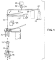
- a probe 10 adapted to enter the interior of a container such as a glass tube 12 which contains a liquid sample 14.
- Container 12 can be positioned upon a lift platform 16 which is adapted to raise the stoppered container.
- a puncture tube 20 which includes a non-coring, hollow needle is disposed above container 12 so that it will puncture stoppered end 15 of container 12 when the container is raised.
- a boom assembly 22 can be provided to lower probe 10 through puncture tube 20 into the interior of container 12 where fluid 14 can be aspirated into probe 10.
- probe 10 is connected by fluid flow path 24 to a syringe pump 26 (and optionally an additional syringe pump 27), see Figure 2, which supplies a diluent liquid 25, such as water, to the probe.
- An air pump 28 is also connected by means of a flow path 29 and T-connection 31 to the fluid flow path 24.
- a solenoid controlled valve 30 is positioned between air pump 28 and the T-connection 31.
- a solenoid-controlled valve 31 is used instead of a separate T-connection, as, with this arrangement, the function of the T-connection is performed by the valve.
- Fluid flow path 29a is supplied with air from a suitable supply 33, with the pressure and flow rate thereof being controlled by means of an air accumulator 34.
- a waste receiving container 35 is positioned at a location such that probe 10 can be pivoted thereover and lowered therein through a probe receiving opening 36.
- Waste receptacle 35 is preferably provided with air venting opening 37, which is provided with a hydrophobic air filter 38 to minimize escape of atomized liquids into the atmosphere, while permitting free escape of air from the waste receptacle.
- Filter 38 can be formed, for example, from an expanded polytetrafluoroethylene fibrous web or membrane.
- a drain opening 39 controlled by valves of conventional design (not shown) is provided for drainage of waste fluid 40 from the bottom of waste receptacle 35. Drainage may be accomplished by gravity flow. Vent opening 37 can be omitted in its entirety if opening 39 is of a size large enough to permit efficient venting of gases from receptacle 35.
- Closure 42 can, alternatively, be formed from bristles 43, a woven fabric 44, or non-woven fabric 45. Closure 42 is kept in a saturated condition by means of liquid 47 which is caused to flow through flow path 48 by means of a suitable pump 49. Fluid 47 is preferably water, but can, depending on the type of fluid being handled by probe 10, constitute or contain a disinfectant material.
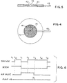
- the effectiveness of the probe wash is enhanced by nearly simultaneous introduction of pressurized air and water which creates a turbulent flow.
- a segmented stream is created in flow path 24 by rapidly causing a burst of air to flow through the probe, followed by diluent liquid.
- the timing of the air flow to the probe, controlled by solenoid valve 30 or 31 is also such that flow path 24 will be filled with diluent liquid at the end of the wash cycle.
- the absence of air is critical to the normal system performance.
- time intervals t 1 to t 0 , t 0 to t 1 , t 1 to t 2 , etc. are preferably in the range of 0.5 to 1.0 second.
- the boom 22 will lower the sample probe 10 into waste receptacle 35 so that the tip of the probe is roughly 10 mm (0.4 inch) into the waste receptacle.
- the syringe pump will charge flow path 24 with diluent.
- the air valve is activated to force air through the system thus forcing contaminated fluid out into waste receptacle 35.
- Pressurized air is vented out of the waste receptacle 35 through vent filter 38.
- the syringe will start to pump liquid through the system.
- the air pump will turn off, allowing fluid to be pumped through all legs of T-coupling 31.
- the solenoid valve turns off allowing the remaining liquid to flush any remaining air out of the tip of probe 10.
- the pump 49 will flood closure 42 with liquid 47 to clean the exterior of probe tip 10.
- the flow of diluent liquid is discontinued and the probe is raised out of the waste receptacle.
- the probe wash method of this invention is used to clean a probe that is used to aspirate a liquid reagent rather than samples of liquids such as bodily fluids, it will be apparent that a stoppered tube would not be used as shown in the drawings. Rather the probe would be inserted into a suitable receptacle, which may have an open top, for aspiration of the desired reagent.
- the probe wash method of this invention is readily adapted to such applications.
Abstract
Description
Claims (6)
- A method of cleaning a probe (10) between the steps of using the probe to aspirate successive aliquots of liquid from successive containers, the method comprising subsequent to discharge of an aliquot of liquid from the probe;characterised by(a) pumping a diluent liquid through said probe; and(b) pumping a pressurised gas through the probe,(c) after step (b) pumping pressurized gas simultaneously with diluent liquid through said probe to form a turbulent flow of liquid and gas, and(d) after step (c) discontinuing the flow of gas through the probe while continuing to pump said diluent liquid into said probe.
- The method of Claim 1, including introducing the tip of the probe (10) into an opening (36) of a vented waste receptacle (35) before step (a), but after discharging said aliquot of liquid from the probe; and
after step (d), withdrawing the probe from the receptacle. - A method according to Claim 1 or 2 wherein a fibrous, air permeable material (45) surrounds the opening (36) to said waste receptacle (35), and a liquid is pumped thereto to wet the same, whereby the exterior of said probe (10) is cleaned, and whereby the escape of aerosols from said receptacle is prevented.
- A method according to Claim 2 or 3 including venting gases from said receptacle (35) through a filtered vent outlet (37).
- The method of claim 1 or 2, when carried out using an apparatus comprising a probe (10), a source of said diluent liquid (25) connected to said probe (10) by means of a first fluid flow path (24), means (26) for pumping said diluent liquid into said fluid flow path at controlled intervals, a source (28,33,34) of pressurised gas connected by a second fluid flow path (29,29a) to the first fluid flow path (24) at a point intermediate to the probe and the source of diluent liquid, valve means (30,31) to control the flow of gas to said probe; and whereinthe method including (e) discontinuing the flow of said diluent liquid and maintaining the valve in the closed position during the next liquid aliquot aspiration cycle.step (a) comprises pumping said diluent liquid into said first fluid flow path (24) and through the probe (10) while maintaining said valve means (30,31) in the closed position,step (b) comprises stopping the pumping of said diluent and opening said valve (30,31) to cause pressurised gas to flow out through said probe (10),step (c) comprises resuming the pumping of said diluent while continuing the flow of said gas,step (d) comprises closing said valve (30,31) and pumping said diluent liquid into the probe,
- The method of any preceding claim, wherein said gas comprises air.
Priority Applications (1)
| Application Number | Priority Date | Filing Date | Title |
|---|---|---|---|
| EP97200915A EP0785434B1 (en) | 1991-12-13 | 1992-12-10 | Probe for aspirating containers with probe cleaning means |
Applications Claiming Priority (3)
| Application Number | Priority Date | Filing Date | Title |
|---|---|---|---|
| US80716191A | 1991-12-13 | 1991-12-13 | |
| US807161 | 1991-12-13 | ||
| PCT/US1992/010661 WO1993012432A1 (en) | 1991-12-13 | 1992-12-10 | Probe wash for liquid analysis apparatus |
Related Child Applications (1)
| Application Number | Title | Priority Date | Filing Date |
|---|---|---|---|
| EP97200915A Division EP0785434B1 (en) | 1991-12-13 | 1992-12-10 | Probe for aspirating containers with probe cleaning means |
Publications (2)
| Publication Number | Publication Date |
|---|---|
| EP0571611A1 EP0571611A1 (en) | 1993-12-01 |
| EP0571611B1 true EP0571611B1 (en) | 1998-01-28 |
Family
ID=25195723
Family Applications (2)
| Application Number | Title | Priority Date | Filing Date |
|---|---|---|---|
| EP97200915A Expired - Lifetime EP0785434B1 (en) | 1991-12-13 | 1992-12-10 | Probe for aspirating containers with probe cleaning means |
| EP93900997A Expired - Lifetime EP0571611B1 (en) | 1991-12-13 | 1992-12-10 | Probe wash for liquid analysis apparatus |
Family Applications Before (1)
| Application Number | Title | Priority Date | Filing Date |
|---|---|---|---|
| EP97200915A Expired - Lifetime EP0785434B1 (en) | 1991-12-13 | 1992-12-10 | Probe for aspirating containers with probe cleaning means |
Country Status (7)
| Country | Link |
|---|---|
| US (1) | US5506142A (en) |
| EP (2) | EP0785434B1 (en) |
| JP (1) | JPH06508216A (en) |
| AU (1) | AU661544B2 (en) |
| CA (1) | CA2101950A1 (en) |
| DE (2) | DE69224285T2 (en) |
| WO (1) | WO1993012432A1 (en) |
Families Citing this family (28)
| Publication number | Priority date | Publication date | Assignee | Title |
|---|---|---|---|---|
| SE503664C2 (en) * | 1994-09-14 | 1996-07-29 | Cma Microdialysis Holding Ab | Liquid absorption device |
| US5750881A (en) * | 1995-07-13 | 1998-05-12 | Chiron Diagnostics Corporation | Method and apparatus for aspirating and dispensing sample fluids |
| US6158269A (en) * | 1995-07-13 | 2000-12-12 | Bayer Corporation | Method and apparatus for aspirating and dispensing sample fluids |
| US5916524A (en) * | 1997-07-23 | 1999-06-29 | Bio-Dot, Inc. | Dispensing apparatus having improved dynamic range |
| USRE38281E1 (en) | 1996-07-26 | 2003-10-21 | Biodot, Inc. | Dispensing apparatus having improved dynamic range |
| AU2775799A (en) * | 1998-02-20 | 1999-09-06 | Cartesian Technologies, Inc. | Methods for microfluidic aspirating and dispensing |
| US6537505B1 (en) | 1998-02-20 | 2003-03-25 | Bio Dot, Inc. | Reagent dispensing valve |
| US20030215957A1 (en) * | 1998-02-20 | 2003-11-20 | Tony Lemmo | Multi-channel dispensing system |
| US6551557B1 (en) | 1998-07-07 | 2003-04-22 | Cartesian Technologies, Inc. | Tip design and random access array for microfluidic transfer |
| US20030207464A1 (en) * | 1999-02-19 | 2003-11-06 | Tony Lemmo | Methods for microfluidic aspirating and dispensing |
| US6463969B1 (en) | 2001-04-10 | 2002-10-15 | Dade Behring Inc. | Liquid sample dispensing methods for precisely delivering liquids without crossover |
| DE10135237A1 (en) * | 2001-07-24 | 2003-02-06 | Mettler Toledo Gmbh | Device for treating a measuring probe and its uses |
| US6746966B1 (en) * | 2003-01-28 | 2004-06-08 | Taiwan Semiconductor Manufacturing Company | Method to solve alignment mark blinded issues and a technology for application of semiconductor etching at a tiny area |
| US20050175499A1 (en) * | 2004-02-06 | 2005-08-11 | Quest Diagnostics Investments Incorporated | Method of reducing cross sample contamination during filter sampling |
| US20060258011A1 (en) * | 2005-04-22 | 2006-11-16 | Igor Shvets | Cleaning of system for dispensing of liquid droplets |
| US7681759B2 (en) * | 2005-05-26 | 2010-03-23 | Cree, Inc. | Fluid-dispensing apparatus with controlled tear-off |
| JP4630786B2 (en) * | 2005-10-04 | 2011-02-09 | キヤノン株式会社 | Biochemical treatment apparatus, DNA amplification and purification apparatus, and DNA testing apparatus including the apparatus |
| US20080099057A1 (en) * | 2006-10-27 | 2008-05-01 | Dade Behring Inc. | Method and Device for Cleaning a Liquid Aspiration and Dispense Probe |
| US8118042B2 (en) | 2008-02-29 | 2012-02-21 | Beckman Coulter, Inc. | Apparatus and method for cleaning a liquid handling probe |
| JP2010286420A (en) * | 2009-06-15 | 2010-12-24 | Hitachi High-Technologies Corp | Cleaning method of dispensing nozzle, automatic analyzer, and container |
| US8438939B1 (en) * | 2009-09-14 | 2013-05-14 | Elemental Scientific, Inc. | Sample introduction system with mixing |
| US9625465B2 (en) | 2012-05-15 | 2017-04-18 | Defined Diagnostics, Llc | Clinical diagnostic systems |
| US9213043B2 (en) | 2012-05-15 | 2015-12-15 | Wellstat Diagnostics, Llc | Clinical diagnostic system including instrument and cartridge |
| US9075042B2 (en) | 2012-05-15 | 2015-07-07 | Wellstat Diagnostics, Llc | Diagnostic systems and cartridges |
| US20150192601A1 (en) * | 2012-07-25 | 2015-07-09 | Siemens Healthcare Diagnostic Inc. | Apparatus, systems, and methods to clean probes in clinical analyzers |
| AU2013337608B2 (en) | 2012-11-01 | 2017-07-20 | Leica Biosystems Melbourne Pty Ltd | A fluid transport system |
| US10792655B2 (en) | 2014-12-10 | 2020-10-06 | Wallac Oy | Dispenser device and a method for rinsing the dispenser device |
| US10401209B2 (en) * | 2016-06-22 | 2019-09-03 | Abbott Laboratories | Liquid level sensing apparatus and related methods |
Family Cites Families (44)
| Publication number | Priority date | Publication date | Assignee | Title |
|---|---|---|---|---|
| BE568202A (en) * | 1957-03-06 | |||
| NL257371A (en) * | 1959-10-30 | |||
| NL113309C (en) * | 1961-10-20 | |||
| NL287532A (en) * | 1962-01-23 | |||
| US3282651A (en) * | 1963-07-12 | 1966-11-01 | Technicon Instr | Sample and reagent and/or wash liquid supply apparatus |
| US3266322A (en) * | 1964-06-15 | 1966-08-16 | Technicon Instr | Automatic liquid sample supply and wash apparatus for automatic analysis system |
| US3484170A (en) * | 1966-04-14 | 1969-12-16 | Technicon Corp | Automatic analysis method and apparatus |
| US3572994A (en) * | 1968-02-27 | 1971-03-30 | Technicon Corp | Analysis system for a liquid stream for a gaseous constituent |
| US3654959A (en) * | 1970-09-04 | 1972-04-11 | Technicon Instr | Fluid supply control method and apparatus for periodic, precise fluid merger |
| US3666420A (en) * | 1970-11-09 | 1972-05-30 | Bodenseewerk Perkin Elmer Co | Apparatus for automatically carrying out chemical analyses |
| US3719086A (en) * | 1971-01-12 | 1973-03-06 | Damon Corp | Liquids sampler with probe-bathing chamber |
| US3872730A (en) * | 1972-03-10 | 1975-03-25 | Becton Dickinson Co | Sampling apparatus |
| US3976429A (en) * | 1973-10-16 | 1976-08-24 | Coulter Electronics, Inc. | Backwash system for diluting apparatus |
| US3912456A (en) * | 1974-03-04 | 1975-10-14 | Anatronics Corp | Apparatus and method for automatic chemical analysis |
| US4076503A (en) * | 1974-08-22 | 1978-02-28 | The Perkin-Elmer Corporation | Pipetting system for use in kinetic analysis apparatus and the like |
| DE2538451C2 (en) * | 1974-09-02 | 1986-06-05 | Technicon Instruments Corp., Tarrytown, N.Y. | Device for withdrawing part of a liquid flow segmented by an immiscible fluid |
| US4000973A (en) * | 1974-09-09 | 1977-01-04 | Beckman Instruments, Inc. | Sample residue cleaning system for biological analyzers |
| DE2448353B2 (en) * | 1974-10-10 | 1977-05-05 | W.C. Heraeus Gmbh, 6450 Hanau | DEVICE FOR THE CARRIAGE-FREE TRANSFER OF A SPECIFIED VOLUME OF SUCCESSIVE LIQUID SAMPLES |
| US3960020A (en) * | 1974-12-30 | 1976-06-01 | Technicon Instruments Corporation | Liquid aspirating probe assembly of a supply analyzer |
| US4015938A (en) * | 1975-11-18 | 1977-04-05 | Technicon Instruments Corporation | Sample supply apparatus and method for automatic analysis systems |
| US4131426A (en) * | 1977-08-24 | 1978-12-26 | Baxter Travenol Laboratories, Inc. | Tip wiper apparatus and method |
| US4148859A (en) * | 1978-05-15 | 1979-04-10 | Coulter Electronics, Inc. | Backwash system for diluting apparatus |
| US4245509A (en) * | 1979-03-16 | 1981-01-20 | Instrumentation Laboratory Inc. | Sampling apparatus |
| JPS55140156A (en) * | 1979-04-19 | 1980-11-01 | Olympus Optical Co Ltd | Distribution method |
| US4283262A (en) * | 1980-07-01 | 1981-08-11 | Instrumentation Laboratory Inc. | Analysis system |
| DE3144083A1 (en) * | 1980-11-14 | 1982-06-24 | Corning Glass Works, 14830 Corning, N.Y. | DEVICE FOR SAMPLING |
| WO1983000296A1 (en) * | 1981-07-20 | 1983-02-03 | American Hospital Supply Corp | Cuvette system for automated chemical analyzer |
| IT1157318B (en) * | 1982-09-06 | 1987-02-11 | Instrumentation Lab Spa | VOLUMETRIC DILUTOR, PARTICULARLY SUITABLE FOR USE ON EQUIPMENT FOR CHEMICAL-CLINICAL ANALYSIS |
| JPS5948657A (en) * | 1982-09-13 | 1984-03-19 | Hitachi Ltd | Sampling mechanism for automatic blood analytical apparatus |
| JPS59119383U (en) * | 1983-02-01 | 1984-08-11 | エーザイ株式会社 | cleaning nozzle |
| US4865993A (en) * | 1985-04-11 | 1989-09-12 | Technicon Instruments Corporation | Minimum carryover container, and analysis system incorporating the same |
| US4871683A (en) * | 1985-04-18 | 1989-10-03 | Beckman Instruments, Inc. | Apparatus and method using a new reaction capsule |
| US4730631A (en) * | 1985-07-22 | 1988-03-15 | Sequoia-Turner Corporation | Probe wash station |
| US4756201A (en) * | 1985-09-03 | 1988-07-12 | Technicon Instruments Corporation | Apparatus and method for combined closed and open tube sampling |
| JPS62242858A (en) * | 1986-04-15 | 1987-10-23 | Nippon Tectron Co Ltd | Cleaning device for probe |
| US4871682A (en) * | 1986-04-30 | 1989-10-03 | Baxter Travenol Laboratories, Inc. | Diluent carryover control |
| US4815978A (en) * | 1986-04-30 | 1989-03-28 | Baxter Travenol Laboratories, Inc. | Clinical analysis methods and systems |
| US4900933A (en) * | 1986-09-08 | 1990-02-13 | C. R. Bard, Inc. | Excitation and detection apparatus for remote sensor connected by optical fiber |
| US4948563A (en) * | 1987-05-08 | 1990-08-14 | Abbott Laboratories | Waste container insert for washing automated immunoassay apparatus probe |
| AU596906B2 (en) * | 1987-06-26 | 1990-05-17 | Beckman Instruments, Inc. | Gas bubble generator |
| JPH0640100B2 (en) * | 1987-11-27 | 1994-05-25 | 株式会社日立製作所 | Automatic analyzer sample dispensing method |
| US4951512A (en) * | 1988-06-23 | 1990-08-28 | Baxter International Inc. | System for providing access to sealed containers |
| JPH063395B2 (en) * | 1988-08-26 | 1994-01-12 | 株式会社日立製作所 | Analyzer with liquid level detection function |
| DE3932641A1 (en) * | 1989-09-29 | 1991-04-11 | Boehringer Mannheim Gmbh | cleaning solution |
-
1992
- 1992-12-10 WO PCT/US1992/010661 patent/WO1993012432A1/en active IP Right Grant
- 1992-12-10 AU AU32465/93A patent/AU661544B2/en not_active Ceased
- 1992-12-10 DE DE69224285T patent/DE69224285T2/en not_active Expired - Fee Related
- 1992-12-10 DE DE69232970T patent/DE69232970D1/en not_active Expired - Lifetime
- 1992-12-10 JP JP5511065A patent/JPH06508216A/en active Pending
- 1992-12-10 EP EP97200915A patent/EP0785434B1/en not_active Expired - Lifetime
- 1992-12-10 EP EP93900997A patent/EP0571611B1/en not_active Expired - Lifetime
- 1992-12-10 CA CA002101950A patent/CA2101950A1/en not_active Abandoned
-
1994
- 1994-09-07 US US08/301,522 patent/US5506142A/en not_active Expired - Fee Related
Also Published As
| Publication number | Publication date |
|---|---|
| AU3246593A (en) | 1993-07-19 |
| US5506142A (en) | 1996-04-09 |
| DE69232970D1 (en) | 2003-04-24 |
| CA2101950A1 (en) | 1993-06-14 |
| AU661544B2 (en) | 1995-07-27 |
| JPH06508216A (en) | 1994-09-14 |
| EP0785434A3 (en) | 1997-09-03 |
| EP0571611A1 (en) | 1993-12-01 |
| DE69224285T2 (en) | 1998-07-23 |
| EP0785434B1 (en) | 2003-03-19 |
| WO1993012432A1 (en) | 1993-06-24 |
| EP0785434A2 (en) | 1997-07-23 |
| DE69224285D1 (en) | 1998-03-05 |
Similar Documents
| Publication | Publication Date | Title |
|---|---|---|
| EP0571611B1 (en) | Probe wash for liquid analysis apparatus | |
| CA2570516C (en) | Probe washing cups and methods | |
| US5408891A (en) | Fluid probe washing apparatus and method | |
| JP2676027B2 (en) | Cleaning device for needles for taking out liquid samples | |
| EP0503003B1 (en) | Apparatus and method for cleaning reagent delivery probes | |
| US5066336A (en) | Method for cleaning reagent delivery probes | |
| EP0858588B1 (en) | Multifunction valve | |
| USRE39600E1 (en) | Liquid sample dispensing methods for precisely delivering liquids without crossover | |
| JPH076997B2 (en) | Sampling device and method | |
| JP2663661B2 (en) | Liquid vacuum suction device | |
| JPH02223860A (en) | Sampling tube washing device | |
| US20220034926A1 (en) | Automatic analyzer | |
| JP2936772B2 (en) | Biochemical automatic analyzer | |
| JPS63246676A (en) | Sample introducing apparatus | |
| JPH1010103A (en) | Automatic sample injector in liquid chromatography device and washing method for the injector | |
| JP2828711B2 (en) | Method and apparatus for supplying sample liquid | |
| JPS5983031A (en) | Liquid sampling and transferring apparatus | |
| JPH0343587B2 (en) | ||
| JPS5984137A (en) | Liquid collection and gyration device | |
| AU2013201496A1 (en) | Telescoping closed-tube sampling assembly | |
| AU2011254007A1 (en) | Telescoping closed-tube sampling assembly |
Legal Events
| Date | Code | Title | Description |
|---|---|---|---|
| PUAI | Public reference made under article 153(3) epc to a published international application that has entered the european phase |
Free format text: ORIGINAL CODE: 0009012 |
|
| 17P | Request for examination filed |
Effective date: 19930813 |
|
| AK | Designated contracting states |
Kind code of ref document: A1 Designated state(s): BE DE ES FR IT LU NL |
|
| RAP1 | Party data changed (applicant data changed or rights of an application transferred) |
Owner name: DADE INTERNATIONAL INC. |
|
| 17Q | First examination report despatched |
Effective date: 19951227 |
|
| GRAG | Despatch of communication of intention to grant |
Free format text: ORIGINAL CODE: EPIDOS AGRA |
|
| GRAG | Despatch of communication of intention to grant |
Free format text: ORIGINAL CODE: EPIDOS AGRA |
|
| GRAH | Despatch of communication of intention to grant a patent |
Free format text: ORIGINAL CODE: EPIDOS IGRA |
|
| GRAH | Despatch of communication of intention to grant a patent |
Free format text: ORIGINAL CODE: EPIDOS IGRA |
|
| GRAA | (expected) grant |
Free format text: ORIGINAL CODE: 0009210 |
|
| AK | Designated contracting states |
Kind code of ref document: B1 Designated state(s): BE DE ES FR IT LU NL |
|
| PG25 | Lapsed in a contracting state [announced via postgrant information from national office to epo] |
Ref country code: NL Free format text: LAPSE BECAUSE OF FAILURE TO SUBMIT A TRANSLATION OF THE DESCRIPTION OR TO PAY THE FEE WITHIN THE PRESCRIBED TIME-LIMIT Effective date: 19980128 Ref country code: ES Free format text: THE PATENT HAS BEEN ANNULLED BY A DECISION OF A NATIONAL AUTHORITY Effective date: 19980128 Ref country code: BE Free format text: LAPSE BECAUSE OF FAILURE TO SUBMIT A TRANSLATION OF THE DESCRIPTION OR TO PAY THE FEE WITHIN THE PRESCRIBED TIME-LIMIT Effective date: 19980128 |
|
| XX | Miscellaneous (additional remarks) |
Free format text: TEILANMELDUNG 97200915.3 EINGEREICHT AM 26/03/97. |
|
| REF | Corresponds to: |
Ref document number: 69224285 Country of ref document: DE Date of ref document: 19980305 |
|
| ET | Fr: translation filed | ||
| ITF | It: translation for a ep patent filed |
Owner name: MODIANO & ASSOCIATI S.R.L. |
|
| NLV1 | Nl: lapsed or annulled due to failure to fulfill the requirements of art. 29p and 29m of the patents act | ||
| PLBE | No opposition filed within time limit |
Free format text: ORIGINAL CODE: 0009261 |
|
| STAA | Information on the status of an ep patent application or granted ep patent |
Free format text: STATUS: NO OPPOSITION FILED WITHIN TIME LIMIT |
|
| PG25 | Lapsed in a contracting state [announced via postgrant information from national office to epo] |
Ref country code: LU Free format text: LAPSE BECAUSE OF NON-PAYMENT OF DUE FEES Effective date: 19981210 |
|
| 26N | No opposition filed | ||
| PGFP | Annual fee paid to national office [announced via postgrant information from national office to epo] |
Ref country code: FR Payment date: 20021119 Year of fee payment: 11 |
|
| PGFP | Annual fee paid to national office [announced via postgrant information from national office to epo] |
Ref country code: DE Payment date: 20021230 Year of fee payment: 11 |
|
| PG25 | Lapsed in a contracting state [announced via postgrant information from national office to epo] |
Ref country code: DE Free format text: LAPSE BECAUSE OF NON-PAYMENT OF DUE FEES Effective date: 20040701 |
|
| PG25 | Lapsed in a contracting state [announced via postgrant information from national office to epo] |
Ref country code: FR Free format text: LAPSE BECAUSE OF NON-PAYMENT OF DUE FEES Effective date: 20040831 |
|
| REG | Reference to a national code |
Ref country code: FR Ref legal event code: ST |
|
| PG25 | Lapsed in a contracting state [announced via postgrant information from national office to epo] |
Ref country code: IT Free format text: LAPSE BECAUSE OF NON-PAYMENT OF DUE FEES;WARNING: LAPSES OF ITALIAN PATENTS WITH EFFECTIVE DATE BEFORE 2007 MAY HAVE OCCURRED AT ANY TIME BEFORE 2007. THE CORRECT EFFECTIVE DATE MAY BE DIFFERENT FROM THE ONE RECORDED. Effective date: 20051210 |