EP0572339A1 - Total prosthesis for the metacarpal-phalangeal joint - Google Patents
Total prosthesis for the metacarpal-phalangeal joint Download PDFInfo
- Publication number
- EP0572339A1 EP0572339A1 EP93420212A EP93420212A EP0572339A1 EP 0572339 A1 EP0572339 A1 EP 0572339A1 EP 93420212 A EP93420212 A EP 93420212A EP 93420212 A EP93420212 A EP 93420212A EP 0572339 A1 EP0572339 A1 EP 0572339A1
- Authority
- EP
- European Patent Office
- Prior art keywords
- head
- curvature
- rod
- radius
- profile
- Prior art date
- Legal status (The legal status is an assumption and is not a legal conclusion. Google has not performed a legal analysis and makes no representation as to the accuracy of the status listed.)
- Granted
Links
Images


Classifications
-
- A—HUMAN NECESSITIES
- A61—MEDICAL OR VETERINARY SCIENCE; HYGIENE
- A61F—FILTERS IMPLANTABLE INTO BLOOD VESSELS; PROSTHESES; DEVICES PROVIDING PATENCY TO, OR PREVENTING COLLAPSING OF, TUBULAR STRUCTURES OF THE BODY, e.g. STENTS; ORTHOPAEDIC, NURSING OR CONTRACEPTIVE DEVICES; FOMENTATION; TREATMENT OR PROTECTION OF EYES OR EARS; BANDAGES, DRESSINGS OR ABSORBENT PADS; FIRST-AID KITS
- A61F2/00—Filters implantable into blood vessels; Prostheses, i.e. artificial substitutes or replacements for parts of the body; Appliances for connecting them with the body; Devices providing patency to, or preventing collapsing of, tubular structures of the body, e.g. stents
- A61F2/02—Prostheses implantable into the body
- A61F2/30—Joints
- A61F2/42—Joints for wrists or ankles; for hands, e.g. fingers; for feet, e.g. toes
- A61F2/4241—Joints for wrists or ankles; for hands, e.g. fingers; for feet, e.g. toes for hands, e.g. fingers
- A61F2002/4251—Joints for wrists or ankles; for hands, e.g. fingers; for feet, e.g. toes for hands, e.g. fingers for metacarpo-phalangeal joints, i.e. MCP or MP joints, e.g. knuckle joints
Definitions
- the present invention relates to a total prosthesis for the metacarpophalangeal joint of each finger of a hand, which comprises two distinct elements making contact with each other via the bone, ligament or muscle structure staying in place.
- Prostheses of this type which generally comprise a block of elastic material implanted in the bony diaphyses to replace the damaged part of the metacarpophalangeal joint. These blocks are shaped so as to reduce as much as possible the stresses due to friction, so that the movement of the prosthesis is then based on the elastic characteristics of the material used.
- the present invention mainly intends to remedy, and this by means of a prosthesis which is capable of reproducing in a perfect manner the movement of the metacarpophalangeal joint.
- Another advantage of the invention consists in producing a total unconstrained prosthesis which allows the entire bone, ligament or muscle structure remaining in place to guide the movement of the metacarpophalangeal joint.
- the total prosthesis of the metacarpophalangeal joint can be used with or without cement.
- the two elements constituting the total prosthesis respectively have articular surfaces which have several radii of curvature and distinct profiles, so that the kinematics differ according to the angular positions of the two elements relative to each other.
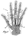
- fig. 1 a right hand 1 whose metacarpophalangeal joints consist of metacarpal bones 10 and phalanges 11, one of these being produced by means of a total prosthesis 2.
- the total prosthesis comprises a first element 3 and a second element 4 which are anchored respectively in the phalangeal and metacarpal diaphysis. These two elements are independent of each other and are in contact only through their articular surfaces which will be better distinguished later.
- the first element 3 of the prosthesis comprises a hollow rod 30 having a tulip-shaped profile to allow its anchoring in the phalangeal diaphysis.
- This rod 30 is adapted to the internal morphology of the bone 11 and can be provided with a device intended to promote anchoring by bone regrowth.
- the rod 30 is provided with a flared head 31 forming the articular part of the phalanx.
- This flared head 31 has two distinct articular surfaces 32 and 33 with a concave profile so as to reproduce the surfaces of the phalangeal bone 11.
- the articular surfaces 32, 33 respectively have a radius of curvature 32 a and 33 a in the shape of a barrel.
- the flared head 31 can for example be attached to the phalangeal rod 30 by means of a pin (not shown) so as to adapt to all the morphologies of a metacarpophalangeal joint.
- the second element 4 comprises a hollow rod 40 having a tulip-shaped profile to allow its anchoring inside the metacarpal diaphysis of the bone 10.
- This rod 40 is adapted to the internal morphology of the bone 10 and can include a device to promote anchoring by bone regrowth.
- a head 41 which has an external shape having the quality of adapting perfectly, in all planes, to the profile provided on the flared head 31 of the first element 30.
- the head 41 comprises, on the side of the rod 40 and on either side of the latter, an inclined face 42 serving to support the bone cut made on the metacarpal articular surface.
- the external shape of the head 41 is divided into two distinct articular surfaces 43 and 44 which come into contact with the articular surfaces 32 and 33 of the phalangeal head 31 so as to adapt to the different angular positions that the total prosthesis can take 2 .
- the articulated surface referenced 43 has a radius of curvature of the cylindrical type 43 a whose edges are rounded according to a profile 43 b .
- the articulated surface referenced 44 is arranged in the middle of the first surface 43 and has a radius of curvature having as its outside profile a ridge in portion of a sphere.
- the articular surface 44 arises in the lower part of the head 41 and in the middle of the radius of curvature 43 a .
- the articulated surface 44 in the form of a ridge divides the articular surface 43 into two equivalent portions, so as to reveal only the edges having a rounded profile 43 b .
- the total prosthesis 2 is shown in the position of maximum extension, that is to say when the hand 1 is for example placed flat on a horizontal or vertical surface.
- first element 3 that is to say the one comprising the phalangeal rod 30, can move laterally relative to the second element 4 which is fixed in the metacarpal shaft of the bone 10.
- the total prosthesis 2 is shown at the start of its flexion, that is to say when the element 3 is inclined at an angle of 30 ° relative to the second element 4 which is provided in a plane horizontal. It can be seen that in this position the radii of curvature 32 a and 33 a of the element 3 are in contact respectively with the rounded edges 43 b of the articular surface 43 and on the other hand with the articular surface 44.
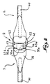
- the prosthesis 2 is shown in total flexion, that is to say when the first element 3 is inclined at an angle of 90 ° relative to the second element 4 which is provided in a horizontal plane.
- the radius of curvature 32 a of the articular surface 32 of the first element 3 is only in contact with the articular surface 43 and more particularly with the rounded edges 43 b of the radius of curvature of cylindrical type 43 a , thus preventing any lateral displacement of the first element 3 relative to the second element 4.
- the total prosthesis allows, thanks to its two articular surfaces 43 and 44 successively entering into function during the movement of the first element 3 relative to the second element 4, to perfectly reproduce the movements recorded in a healthy metacarpophalangeal joint.
Abstract
Description
La présente invention a pour objet une prothèse totale pour l'articulation métacarpo-phalangienne de chaque doigt d'une main, qui comprend deux éléments distincts prenant contact l'un avec l'autre par l'intermédiaire de la structure osseuse, ligamentaire ou musculaire restant en place.The present invention relates to a total prosthesis for the metacarpophalangeal joint of each finger of a hand, which comprises two distinct elements making contact with each other via the bone, ligament or muscle structure staying in place.
On connaît des prothèses de ce genre qui comprennent généralement un bloc de matériau élastique implanté dans les diaphyses osseuses pour remplacer la partie de l'articulation métacarpo-phalangienne endommagée. Ces blocs sont conformés de manière à réduire le plus possible les contraintes dues au frottement, de manière que le mouvement de la prothèse soit alors basé sur les caractéristiques élastiques du matériau employé.Prostheses of this type are known which generally comprise a block of elastic material implanted in the bony diaphyses to replace the damaged part of the metacarpophalangeal joint. These blocks are shaped so as to reduce as much as possible the stresses due to friction, so that the movement of the prosthesis is then based on the elastic characteristics of the material used.
De telles prothèses comportent certains inconvénients en ce qui concerne tant la durée de vie des blocs élastiques, notablement courte, que les contraintes que ces blocs engendrent sur l'articulation du fait de leur conception rudimentaire.Such prostheses have certain drawbacks as regards both the life of the elastic blocks, which is notably short, and the stresses which these blocks generate on the joint due to their rudimentary design.
On connaît aussi des prothèses métalliques qui assimilent l'articulation métacarpo-phalangienne à une articulation du type charnière. Ces prothèses ne sont pas susceptibles de reproduire parfaitement la cinématique normale de l'articulation, ce qui entraîne des complications importantes. Ces complications sont généralement dues aux contraintes que la prothèse engendre sur l'articulation et qui se traduisent par un descellement du corps de la prothèse.Metallic prostheses are also known which assimilate the metacarpophalangeal joint to a hinge-type joint. These prostheses are not capable of perfectly reproducing the normal kinematics of the joint, which leads to significant complications. These complications are generally due to the stresses which the prosthesis creates on the joint and which result in a loosening of the body of the prosthesis.
C'est à ces inconvénients qu'entend remédier principalement la présente invention, et ce à l'aide d'une prothèse qui est susceptible de reproduire de manière parfaite le mouvement de l'articulation métacarpophalangienne.It is these drawbacks that the present invention mainly intends to remedy, and this by means of a prosthesis which is capable of reproducing in a perfect manner the movement of the metacarpophalangeal joint.
La prothèse totale suivant l'invention comprend :
- un premier élément comportant une tige pour son ancrage dans la diaphyse phalangienne et une tête évasée pourvue d'au moins deux surfaces articulaires à profil concave présentant chacune un rayon de courbure distinct en forme de tonneau ;
- et un second élément pourvu d'une tige pour l'ancrage dans la diaphyse métacarpienne et d'une tête comportant un profil extérieur ayant au moins deux surfaces articulaires distinctes présentant respectivement un premier rayon de courbure du type circulaire dont les bords sont arrondis, et un second rayon de courbure en forme de crête en portion de sphère prenant naissance dans la partie inférieure de la tête et au milieu du premier rayon de courbure.
- a first element comprising a rod for its anchoring in the phalangeal diaphysis and a flared head provided with at least two articular surfaces with concave profile each having a distinct radius of curvature in the shape of a barrel;
- and a second element provided with a rod for anchoring in the metacarpal diaphysis and with a head comprising an external profile having at least two distinct articular surfaces having respectively a first radius of curvature of the circular type whose edges are rounded, and a second radius of curvature in the form of a ridge in portion of a sphere originating in the lower part of the head and in the middle of the first radius of curvature.
Un autre avantage de l'invention consiste à réaliser une prothèse totale non contrainte qui permet à l'ensemble de la structure osseuse ou ligamentaire ou musculaire restant en place de guider le mouvement de l'articulation métacarpo-phalangienne.Another advantage of the invention consists in producing a total unconstrained prosthesis which allows the entire bone, ligament or muscle structure remaining in place to guide the movement of the metacarpophalangeal joint.
La prothèse totale de l'articulation métacarpo-phalangienne est utilisable avec ou sans ciment. En outre, les deux éléments constituant la prothèse totale présentent respectivement des surfaces articulaires qui comportent plusieurs rayons de courbure et de profils distincts, de manière que la cinématique diffère suivant les positions angulaires des deux éléments l'un par rapport à l'autre.The total prosthesis of the metacarpophalangeal joint can be used with or without cement. In addition, the two elements constituting the total prosthesis respectively have articular surfaces which have several radii of curvature and distinct profiles, so that the kinematics differ according to the angular positions of the two elements relative to each other.
Le dessin annexé, donné à titre d'exemple, permettra de mieux comprendre l'invention, les caractéristiques qu'elle présente et les avantages qu'elle est susceptible de procurer :
- Fig. 1 est une vue d'ensemble représentant les os constituant une main droite dont l'une des articulations métacarpo-phalangiennes est réalisée par une prothèse totale suivant l'invention.
- Fig. 2 est une vue latérale avec coupe partielle illustrant l'agencement de la prothèse totale en position d'extension.
- Fig. 3 est une coupe partielle agrandie suivant III-III de fig. 2, montrant les surfaces articulaires des deux éléments qui sont en contact en position d'extension.
- Fig. 4 est une vue de dessus montrant la prothèse totale dans la même position que celle suivant fig. 1.
- Fig. 5 est une vue latérale semblable à celle de fig. 1, mais montrant la prothèse totale dans une position de flexion phalangienne inclinée d'un angle de 30° vers le bas par rapport à un plan horizontal.
- Fig. 6 est une coupe partielle agrandie suivant VI-VI de fig. 5 montrant les surfaces articulaires des deux éléments qui sont en contact en position de flexion inclinée suivant fig. 5.
- Fig. 7 est une vue latérale avec coupe partielle représentant la prothèse totale dans une position de flexion phalangienne inclinée d'un angle de 90° par rapport à un plan horizontal.
- Fig. 8 est une coupe partielle agrandie suivant VIII-VIII de fig. 7 montrant les surfaces articulaires des deux éléments qui sont en contact en position de flexion inclinée suivant fig. 7.
- Fig. 1 is an overall view representing the bones constituting a right hand, one of the metacarpophalangeal joints is produced by a total prosthesis according to the invention.
- Fig. 2 is a side view with partial section illustrating the arrangement of the total prosthesis in the extended position.
- Fig. 3 is an enlarged partial section along III-III of FIG. 2, showing the articular surfaces of the two elements which are in contact in the extended position.
- Fig. 4 is a top view showing the total prosthesis in the same position as that according to FIG. 1.
- Fig. 5 is a side view similar to that of FIG. 1, but showing the total prosthesis in a phalangeal flexion position inclined at an angle of 30 ° downward from a horizontal plane.
- Fig. 6 is an enlarged partial section along VI-VI of FIG. 5 showing the articular surfaces of the two elements which are in contact in the inclined flexion position according to FIG. 5.
- Fig. 7 is a side view with partial section showing the total prosthesis in a phalangeal flexion position inclined at an angle of 90 ° relative to a horizontal plane.
- Fig. 8 is an enlarged partial section along VIII-VIII of FIG. 7 showing the articular surfaces of the two elements which are in contact in the inclined flexion position according to FIG. 7.
On a représenté en fig. 1 une main droite 1 dont les articulations métacarpo-phalangiennes sont constituées par des os métacarpiens 10 et des phalanges 11, l'une de celles-ci étant réalisé par l'intermédiaire d'une prothèse totale 2.There is shown in fig. 1 a
La prothèse totale comprend un premier élément 3 et un second élément 4 qui sont ancrés respectivement dans la diaphyse phalangienne et métacarpienne. Ces deux éléments sont indépendants l'un de l'autre et sont en contact uniquement par l'intermédiaire de leurs surfaces articulaires que l'on distinguera mieux plus loin.The total prosthesis comprises a
Comme illustré en fig. 2, le premier élément 3 de la prothèse comporte une tige creuse 30 présentant un profil en forme de tulipe pour permettre son ancrage dans la diaphyse phalangienne. Cette tige 30 est adaptée à la morphologie interne de l'os 11 et peut être pourvue d'un dispositif visant à promouvoir un ancrage par repousse osseuse.As illustrated in fig. 2, the
A l'une de ses extrémités, la tige 30 est pourvue d'une tête évasée 31 formant la partie articulaire de la phalange. Cette tête évasée 31 comporte deux surfaces articulaires distinctes 32 et 33 à profil concave de manière à reproduire les surfaces de l'os phalangien 11. Les surfaces articulaires 32, 33 présentent respectivement un rayon de courbures 32a et 33a en forme de tonneau. La tête évasée 31 peut être par exemple rapportée sur la tige phalangienne 30 par l'intermédiaire d'une goupille (non représentée) de manière à s'adapter à toutes les morphologies d'une articulation métacarpo-phalangienne.At one of its ends, the
Le second élément 4 comprend une tige creuse 40 présentant un profil en forme de tulipe pour permettre son ancrage à l'intérieur de la diaphyse métacarpienne de l'os 10. Cette tige 40 est adaptée à la morphologie interne de l'os 10 et peut comprendre un dispositif visant à promouvoir un ancrage par repousse osseuse.The
A l'une des extrémités de la tige 40 est prévue une tête 41 qui présente une forme extérieure ayant pour qualité de s'adapter parfaitement, dans tous les plans, au profil prévu sur la tête évasée 31 du premier élément 30. La tête 41 comprend, du côté de la tige 40 et de part et d'autre de celle-ci, un pan incliné 42 servant d'appui à la coupe osseuse ménagée sur la surface articulaire métacarpienne. La forme extérieure de la tête 41 se divise en deux surfaces articulaires distinctes 43 et 44 qui viennent en contact avec les surfaces articulaires 32 et 33 de la tête phalangienne 31 de manière à s'adapter aux différentes positions angulaires que peut prendre la prothèse totale 2.At one end of the
La surface articulaire référencée 43 présente un rayon de courbure du type cylindrique 43a dont les bords sont arrondis suivant un profil 43b. La surface articulaire référencée 44 est disposée au milieu de la première surface 43 et présente un rayon de courbure ayant comme profil extérieur une crête en portion de sphère. La surface articulaire 44 prend naissance dans la partie inférieure de la tête 41 et au milieu du rayon de courbure 43a. Dans la partie supérieure de la tête 41, la surface articulaire 44 en forme de crête divise en deux portions équivalentes la surface articulaire 43, de manière à ne laisser apparaître que les bords ayant un profil arrondi 43b.The articulated surface referenced 43 has a radius of curvature of the
En fig. 2, 3 et 4, on a représenté la prothèse totale 2 en position d'extension maximale, c'est-à-dire lorsque la main 1 est par exemple posée à plat sur une surface horizontale ou verticale.In fig. 2, 3 and 4, the
Ainsi, en fig. 3, on a montré en détail les surfaces articulaires du premier élément 3 et du second élément 4 qui viennent en contact l'une avec l'autre. On remarque que dans cette position d'extension, seule la surface articulaire 44 ayant comme profil extérieur une crête en portion de sphère et appartenant au second élément 4 est en contact avec le rayon de courbure 32a de la surface 33 du premier élément 3.Thus, in fig. 3, there is shown in detail the articular surfaces of the
On note aussi que dans cette position le premier élément 3, c'est-à-dire celui comportant la tige phalangienne 30, peut se déplacer latéralement par rapport au second élément 4 qui est fixé dans la diaphyse métacarpienne de l'os 10.We also note that in this position the
En fig. 5 et 6, on a représenté la prothèse totale 2 au début de sa flexion, c'est-à-dire lorsque l'élément 3 est incliné d'un angle de 30° par rapport au second élément 4 qui est prévu dans un plan horizontal. On constate que dans cette position les rayons de courbure 32a et 33a de l'élément 3 sont en contact respectivement avec les bords arrondis 43b de la surface articulaire 43 et d'autre part avec la surface articulaire 44.In fig. 5 and 6, the
On observera également que le début de la surface articulaire 44 en forme de crête sphérique est réalisé en harmonie avec le profil de la surface articulaire 43 pour ne pas gêner les mouvements de flexion et d'extension du premier élément 3 par rapport au second élément 4. Dans cette position inclinée à 30°, les déplacements latéraux du premier élément 3 sont limités, étant donné que le rayon de courbure 32a commence à prendre appui sur les bords arrondis 43b de la surface articulaire 43.It will also be observed that the beginning of the
En fig. 7 et 8, la prothèse 2 est représentée en flexion totale, c'est-à-dire lorsque le premier élément 3 se trouve incliné d'un angle de 90° par rapport au second élément 4 qui est prévu dans un plan horizontal. Dans cette position, le rayon de courbure 32a de la surface articulaire 32 du premier élément 3 est uniquement en contact avec la surface articulaire 43 et plus particulièrement avec les bords arrondis 43b du rayon de courbure de type cylindrique 43a, empêchant ainsi tout déplacement latéral du premier élément 3 par rapport au second élément 4.In fig. 7 and 8, the
On note que la prothèse totale permet, grâce à ses deux surfaces articulaires 43 et 44 entrant successivement en fonction au cours du mouvement du premier élément 3 par rapport au second élément 4, de reproduire parfaitement les mouvements enregistrés dans une articulation métacarpo-phalangienne saine.It is noted that the total prosthesis allows, thanks to its two
Claims (7)
Applications Claiming Priority (2)
| Application Number | Priority Date | Filing Date | Title |
|---|---|---|---|
| FR9206588 | 1992-05-25 | ||
| FR9206588A FR2691357A1 (en) | 1992-05-25 | 1992-05-25 | Total prosthesis for the metacarpophalangeal joint. |
Publications (2)
| Publication Number | Publication Date |
|---|---|
| EP0572339A1 true EP0572339A1 (en) | 1993-12-01 |
| EP0572339B1 EP0572339B1 (en) | 1996-12-04 |
Family
ID=9430299
Family Applications (1)
| Application Number | Title | Priority Date | Filing Date |
|---|---|---|---|
| EP93420212A Expired - Lifetime EP0572339B1 (en) | 1992-05-25 | 1993-05-25 | Total prosthesis for the metacarpal-phalangeal joint |
Country Status (5)
| Country | Link |
|---|---|
| US (1) | US5405399A (en) |
| EP (1) | EP0572339B1 (en) |
| DE (1) | DE69306307T2 (en) |
| ES (1) | ES2095612T3 (en) |
| FR (1) | FR2691357A1 (en) |
Cited By (6)
| Publication number | Priority date | Publication date | Assignee | Title |
|---|---|---|---|---|
| US5405401A (en) * | 1993-10-05 | 1995-04-11 | Orthomet, Inc. | Prosthesis for replacement of joints between long bones in the hand |
| US5674297A (en) * | 1995-12-08 | 1997-10-07 | Lane; Lewis B. | Metacarpophalangeal prosthesis |
| US5776203A (en) * | 1997-01-13 | 1998-07-07 | Spalding; Robert Tucker | Metatarsal phalangeal sesamoid prosthetic joint |
| NL1009550C2 (en) * | 1998-07-03 | 2000-01-10 | Straten Beheer B V Van | Joint prosthesis, in particular finger joint prosthesis. |
| FR2787013A1 (en) * | 1998-12-14 | 2000-06-16 | Depuy France | TOTAL METATARSO-PHALANGIAN CUT PROSTHESIS |
| WO2010079288A1 (en) | 2009-01-08 | 2010-07-15 | Memometal Technologies, Société Anonyme | Orthopaedic implant for arthroplasty of the fingers |
Families Citing this family (41)
| Publication number | Priority date | Publication date | Assignee | Title |
|---|---|---|---|---|
| FR2743717B1 (en) * | 1996-01-23 | 1998-04-30 | Maksene Philippe | PHALANGIAN JOINT PROSTHESIS |
| US5782927A (en) * | 1996-11-06 | 1998-07-21 | Ascension Orthopedics, Inc. | Metacarpal-phalangeal joint replacement |
| FR2768613B1 (en) * | 1997-09-23 | 1999-12-17 | Tornier Sa | KNEE PROSTHESIS WITH ROTATABLE PLATFORM |
| US5938700A (en) * | 1998-02-11 | 1999-08-17 | Engineering Consulting Services, Inc. | Constrained prosthesis for replacement of joints between long bones in the hand |
| DE19925529A1 (en) * | 1999-06-04 | 2000-12-07 | Moje Hans Juergen | Endoprosthesis for finger joints comprises proximal and distal joint parts of bioceramic material with a shaft of material shifted radially that can be inserted |
| US8366785B1 (en) | 1999-07-14 | 2013-02-05 | Biopro, Inc. | Basal thumb joint implant |
| FR2797178B1 (en) * | 1999-08-05 | 2002-02-22 | Tornier Sa | MALLEOLAR IMPLANT FOR PARTIAL OR TOTAL ANKLE PROSTHESIS AND ANCILLARY MATERIAL FOR PLACING SUCH AN IMPLANT |
| FR2826860B1 (en) * | 2001-07-09 | 2004-03-05 | Tornier Sa | ANCILLARY OF POSITION OF A CUBITAL COMPONENT AND / OR A RADIAL COMPONENT OF ELBOW PROSTHESIS |
| FR2826859B1 (en) * | 2001-07-09 | 2003-09-19 | Tornier Sa | ANCILLARY OF LAYING OF A HUMERAL COMPONENT OF ELBOW PROSTHESIS |
| FR2827500B1 (en) * | 2001-07-17 | 2004-04-02 | Tornier Sa | PLATE OF OSTEOSYNTHESIS OF THE UPPER END OF THE HUMERUS |
| FR2848183B1 (en) * | 2002-12-10 | 2006-01-27 | Tornier Sa | STERILE CONDITIONING METHOD OF A POLYETHYLENE PROTHETIC IMPLANT |
| FR2850010B1 (en) * | 2003-01-17 | 2005-12-02 | Tornier Sa | ANCILLARY FOR THE INSTALLATION OF A PROTHETIC COTYL FOR A HIP PROSTHESIS |
| US7887544B2 (en) | 2003-03-10 | 2011-02-15 | Tornier Sas | Ancillary tool for positioning a glenoid implant |
| FR2854792B1 (en) * | 2003-05-12 | 2005-09-09 | Tornier Sa | GAME OF PROTHETIC ELEMENTS FOR A TIBIAL PROTHETIC SET |
| FR2855397B1 (en) | 2003-05-28 | 2005-07-15 | Tornier Sa | ELBOW PROSTHESIS |
| FR2863865B1 (en) | 2003-12-19 | 2006-10-06 | Tornier Sa | SHOULDER OR HIP PROSTHESIS AND METHOD OF MOUNTING |
| FR2865928B1 (en) | 2004-02-10 | 2006-03-17 | Tornier Sa | SURGICAL DEVICE FOR IMPLANTATION OF A TOTAL HIP PROSTHESIS |
| US8303665B2 (en) | 2004-06-15 | 2012-11-06 | Tornier Sas | Glenoidal component, set of such components and shoulder prosthesis incorporating such a glenoidal component |
| FR2871371B1 (en) | 2004-06-15 | 2007-04-06 | Tornier Sas | GLENOIDAL COMPONENT OF SHOULDER PROSTHESIS, SET OF COMPONENT ELEMENTS OF SUCH COMPONENT AND TOTAL SHOULDER PROSTHESIS INCORPORATING SUCH COMPONENT |
| US7678150B2 (en) * | 2004-06-15 | 2010-03-16 | Tornier Sas | Total shoulder prosthesis of an inverted type |
| FR2871368B1 (en) * | 2004-06-15 | 2006-08-25 | Tornier Sas | SET OF HUMERAL COMPONENTS FOR TOTAL SHOULDER PROSTHESIS |
| FR2872025B1 (en) * | 2004-06-28 | 2006-08-25 | Tornier Sas | PROSTHESIS OF SHOULDER OR HIP |
| FR2881340B1 (en) * | 2005-02-01 | 2008-01-11 | Tornier Sas | HUMERAL NUTS |
| FR2884408B1 (en) * | 2005-04-13 | 2007-05-25 | Tornier Sas | SURGICAL DEVICE FOR IMPLANTATION OF A PARTIAL OR TOTAL KNEE PROSTHESIS |
| FR2884407B1 (en) * | 2005-04-13 | 2007-05-25 | Tornier Sas | SURGICAL DEVICE FOR IMPLANTATION OF A PARTIAL OR TOTAL KNEE PROSTHESIS |
| US7468077B2 (en) * | 2005-08-02 | 2008-12-23 | Tornier Sas | Patellar retractor and method of surgical procedure on knee |
| FR2896404B1 (en) | 2006-01-24 | 2008-02-29 | Tornier Sas | SURGICAL INSTRUMENTATION ASSEMBLY FOR POSTING AN ANKLE PROSTHESIS |
| FR2896684B1 (en) * | 2006-02-01 | 2008-09-26 | Tornier Soc Par Actions Simplifiee | TIBIAL IMPLANT WITH OFFSET SHAFT |
| FR2899790B1 (en) | 2006-04-13 | 2008-06-13 | Tornier Sas | GLENOIDAL COMPONENT FOR TOTAL SHOULDER PROSTHESIS, SET OF SUCH COMPONENTS, AND TOTAL SHOULDER PROSTHESIS COMPRISING SUCH A COMPONENT |
| FR2900045B1 (en) * | 2006-04-21 | 2009-01-16 | Tornier Sas | PROSTHESIS OF SHOULDER OR HIP |
| FR2903157B1 (en) * | 2006-06-29 | 2009-10-30 | Bioprofile Sa | ASSEMBLY OF A PIECE OF PYROCARBON AND ANOTHER PIECE |
| FR2906999B1 (en) | 2006-10-13 | 2009-06-05 | Tornier Sas | PROTHETIC SET OF ANKLE |
| FR2940759B1 (en) * | 2009-01-08 | 2011-10-07 | Memometal Technologies | INTRA MEDULLAIRE ANCHORING ROD FOR ORTHOPEDIC IMPLANT HEAD |
| FR2966343B1 (en) | 2010-10-22 | 2012-12-07 | Tornier Sa | SET OF GLENOIDIAN COMPONENTS OF SHOULDER PROSTHESIS |
| US9132019B2 (en) | 2012-10-22 | 2015-09-15 | Andrew C. Weems | Metacarpal-phalangeal prosthesis |
| US9681960B2 (en) | 2014-05-16 | 2017-06-20 | Howmedica Osteonics Corp. | Guides for fracture system |
| US10575968B2 (en) | 2014-05-16 | 2020-03-03 | Howmedica Osteonics Corp. | Guides for fracture system |
| FR3021524A1 (en) | 2014-06-02 | 2015-12-04 | Small Bone Innovations Internat | METACARPIAN ANCHORING ROD, IN PARTICULAR FOR A TRAPEZO-METACARPIAN PROSTHESIS |
| ES2747364T3 (en) * | 2015-04-15 | 2020-03-10 | 41Hemiverse Ag | Artificial joint implant |
| ES2696546A1 (en) * | 2017-07-12 | 2019-01-16 | Pedreno Conrado Miguel Bano | Metacarpal prosthesis with range of ulnar and radial movement (Machine-translation by Google Translate, not legally binding) |
| CN112370219B (en) * | 2020-11-05 | 2024-02-20 | 中国人民解放军陆军军医大学第一附属医院 | Bone joint prosthesis |
Citations (4)
| Publication number | Priority date | Publication date | Assignee | Title |
|---|---|---|---|---|
| FR2269324A1 (en) * | 1974-05-03 | 1975-11-28 | Nat Res Dev | |
| US4242759A (en) * | 1979-03-12 | 1981-01-06 | Ontario Research Foundation | M.C.P. Joint replacement |
| US4731087A (en) * | 1987-01-06 | 1988-03-15 | New York Society For The Relief Of The Ruptured And Crippled | Metatarsal-phalangeal prosthesis |
| FR2668703A3 (en) * | 1990-11-06 | 1992-05-07 | Impact | Total knee prosthesis |
Family Cites Families (4)
| Publication number | Priority date | Publication date | Assignee | Title |
|---|---|---|---|---|
| CH665553A5 (en) * | 1985-02-07 | 1988-05-31 | Sulzer Ag | METAL BONE IMPLANT. |
| US4725280A (en) * | 1986-03-28 | 1988-02-16 | Laure Prosthetics, Inc. | Finger implant |
| GB9018782D0 (en) * | 1990-08-28 | 1990-10-10 | Goodfellow John W | Phosthetic femoral components |
| GB9102633D0 (en) * | 1991-02-07 | 1991-03-27 | Finsbury Instr Ltd | Knee prosthesis |
-
1992
- 1992-05-25 FR FR9206588A patent/FR2691357A1/en active Granted
-
1993
- 1993-05-11 US US08/059,362 patent/US5405399A/en not_active Expired - Lifetime
- 1993-05-25 ES ES93420212T patent/ES2095612T3/en not_active Expired - Lifetime
- 1993-05-25 DE DE69306307T patent/DE69306307T2/en not_active Expired - Fee Related
- 1993-05-25 EP EP93420212A patent/EP0572339B1/en not_active Expired - Lifetime
Patent Citations (4)
| Publication number | Priority date | Publication date | Assignee | Title |
|---|---|---|---|---|
| FR2269324A1 (en) * | 1974-05-03 | 1975-11-28 | Nat Res Dev | |
| US4242759A (en) * | 1979-03-12 | 1981-01-06 | Ontario Research Foundation | M.C.P. Joint replacement |
| US4731087A (en) * | 1987-01-06 | 1988-03-15 | New York Society For The Relief Of The Ruptured And Crippled | Metatarsal-phalangeal prosthesis |
| FR2668703A3 (en) * | 1990-11-06 | 1992-05-07 | Impact | Total knee prosthesis |
Cited By (12)
| Publication number | Priority date | Publication date | Assignee | Title |
|---|---|---|---|---|
| US5405401A (en) * | 1993-10-05 | 1995-04-11 | Orthomet, Inc. | Prosthesis for replacement of joints between long bones in the hand |
| EP0746275A1 (en) * | 1993-10-05 | 1996-12-11 | Mayo Foundation For Medical Education And Research | Prosthesis for replacement of joints between long bones in the hand |
| EP0746275A4 (en) * | 1993-10-05 | 1997-11-12 | Orthomet Inc | Prosthesis for replacement of joints between long bones in the hand |
| US5674297A (en) * | 1995-12-08 | 1997-10-07 | Lane; Lewis B. | Metacarpophalangeal prosthesis |
| US5776203A (en) * | 1997-01-13 | 1998-07-07 | Spalding; Robert Tucker | Metatarsal phalangeal sesamoid prosthetic joint |
| NL1009550C2 (en) * | 1998-07-03 | 2000-01-10 | Straten Beheer B V Van | Joint prosthesis, in particular finger joint prosthesis. |
| WO2000001327A3 (en) * | 1998-07-03 | 2000-02-24 | Straten Beheer B V Van | Joint prosthesis, in particular finger joint prosthesis |
| US6352560B1 (en) | 1998-07-03 | 2002-03-05 | Van Straten Beheer B.V. | Joint prosthesis |
| FR2787013A1 (en) * | 1998-12-14 | 2000-06-16 | Depuy France | TOTAL METATARSO-PHALANGIAN CUT PROSTHESIS |
| WO2000035381A1 (en) * | 1998-12-14 | 2000-06-22 | Depuy France | Total metatarsophalangeal prosthesis with section plane |
| AU776010B2 (en) * | 1998-12-14 | 2004-08-26 | Depuy France | Total metatarsophalangeal prosthesis with section plane |
| WO2010079288A1 (en) | 2009-01-08 | 2010-07-15 | Memometal Technologies, Société Anonyme | Orthopaedic implant for arthroplasty of the fingers |
Also Published As
| Publication number | Publication date |
|---|---|
| FR2691357B1 (en) | 1994-07-13 |
| ES2095612T3 (en) | 1997-02-16 |
| EP0572339B1 (en) | 1996-12-04 |
| DE69306307D1 (en) | 1997-01-16 |
| US5405399A (en) | 1995-04-11 |
| DE69306307T2 (en) | 1997-04-30 |
| FR2691357A1 (en) | 1993-11-26 |
Similar Documents
| Publication | Publication Date | Title |
|---|---|---|
| EP0572339B1 (en) | Total prosthesis for the metacarpal-phalangeal joint | |
| EP0532440B1 (en) | Total wrist prosthesis | |
| EP0857472B1 (en) | Total elbow prosthesis | |
| EP0310483B1 (en) | Metacarpal-phalangeal or inter-phalangeal articulation prosthesis of the finger | |
| EP0516567B1 (en) | Shock-absorbing device for intervertebral stabilisation | |
| US4242759A (en) | M.C.P. Joint replacement | |
| EP1263352B1 (en) | Disc prosthesis for cervical vertebra | |
| FR2944694A1 (en) | DEVICE FOR FIXING THE GLENE OF A GLENOIDAL ARTICULAR COMPONENT FOR A SHOULDER PROSTHESIS AND A CORRESPONDING SHOULDER PROSTHESIS | |
| FR2676917A1 (en) | Ankle prosthesis | |
| EP1196118A1 (en) | Novel knee prosthesis | |
| FR2578162A1 (en) | Cup for total prosthesis of the hip or of the shoulder | |
| WO2005046534A1 (en) | Total intervertebral-disc prothesis | |
| FR2605878A1 (en) | Prosthesis for small joints, in particular metacarpophalangial and interphalangial joints | |
| FR2465470A1 (en) | Articulated joint surgical prosthesis - has twin spherical surfaces in each mating part with prolongations for lateral movement | |
| US4150444A (en) | Prosthetic joint | |
| EP0611225B1 (en) | Femoral stem for hip prothesis | |
| FR2541890A1 (en) | Total shoulder prosthesis | |
| EP2276427A1 (en) | Trapezio-metacarpal joint prosthesis | |
| EP1159939B1 (en) | Total wrist prosthesis | |
| EP0359672B1 (en) | Articulation prosthesis, in particular a hip prosthesis, with a self-damping property | |
| FR2626168A1 (en) | Modular hip prosthesis | |
| FR2736818A1 (en) | PROSTHESIS FOR ARTICULATION FOR FLEXION WITH CERTAIN LATERAL LAXITY | |
| FR2703904A1 (en) | Trapezo-metacarpal prosthesis. | |
| FR2734150A1 (en) | Joint construction for e.g. knuckle replacement prosthesis implant | |
| FR2647670A1 (en) | Shoulder prosthesis device |
Legal Events
| Date | Code | Title | Description |
|---|---|---|---|
| PUAI | Public reference made under article 153(3) epc to a published international application that has entered the european phase |
Free format text: ORIGINAL CODE: 0009012 |
|
| AK | Designated contracting states |
Kind code of ref document: A1 Designated state(s): CH DE ES FR GB IT LI |
|
| 17P | Request for examination filed |
Effective date: 19931229 |
|
| 17Q | First examination report despatched |
Effective date: 19950727 |
|
| GRAG | Despatch of communication of intention to grant |
Free format text: ORIGINAL CODE: EPIDOS AGRA |
|
| RAP1 | Party data changed (applicant data changed or rights of an application transferred) |
Owner name: ETABLISSEMENTS TORNIER |
|
| GRAH | Despatch of communication of intention to grant a patent |
Free format text: ORIGINAL CODE: EPIDOS IGRA |
|
| RAP1 | Party data changed (applicant data changed or rights of an application transferred) |
Owner name: TORNIER SA |
|
| GRAH | Despatch of communication of intention to grant a patent |
Free format text: ORIGINAL CODE: EPIDOS IGRA |
|
| ITF | It: translation for a ep patent filed |
Owner name: SOCIETA' ITALIANA BREVETTI S.P.A. |
|
| GRAA | (expected) grant |
Free format text: ORIGINAL CODE: 0009210 |
|
| AK | Designated contracting states |
Kind code of ref document: B1 Designated state(s): CH DE ES FR GB IT LI |
|
| REF | Corresponds to: |
Ref document number: 69306307 Country of ref document: DE Date of ref document: 19970116 |
|
| REG | Reference to a national code |
Ref country code: ES Ref legal event code: FG2A Ref document number: 2095612 Country of ref document: ES Kind code of ref document: T3 |
|
| GBT | Gb: translation of ep patent filed (gb section 77(6)(a)/1977) |
Effective date: 19970130 |
|
| PLBE | No opposition filed within time limit |
Free format text: ORIGINAL CODE: 0009261 |
|
| STAA | Information on the status of an ep patent application or granted ep patent |
Free format text: STATUS: NO OPPOSITION FILED WITHIN TIME LIMIT |
|
| 26N | No opposition filed | ||
| PGFP | Annual fee paid to national office [announced via postgrant information from national office to epo] |
Ref country code: GB Payment date: 19980519 Year of fee payment: 6 |
|
| PGFP | Annual fee paid to national office [announced via postgrant information from national office to epo] |
Ref country code: ES Payment date: 19980525 Year of fee payment: 6 |
|
| PG25 | Lapsed in a contracting state [announced via postgrant information from national office to epo] |
Ref country code: GB Free format text: LAPSE BECAUSE OF NON-PAYMENT OF DUE FEES Effective date: 19990525 |
|
| PG25 | Lapsed in a contracting state [announced via postgrant information from national office to epo] |
Ref country code: ES Free format text: LAPSE BECAUSE OF EXPIRATION OF PROTECTION Effective date: 19990526 |
|
| GBPC | Gb: european patent ceased through non-payment of renewal fee |
Effective date: 19990525 |
|
| REG | Reference to a national code |
Ref country code: ES Ref legal event code: FD2A Effective date: 20010601 |
|
| PG25 | Lapsed in a contracting state [announced via postgrant information from national office to epo] |
Ref country code: IT Free format text: LAPSE BECAUSE OF NON-PAYMENT OF DUE FEES;WARNING: LAPSES OF ITALIAN PATENTS WITH EFFECTIVE DATE BEFORE 2007 MAY HAVE OCCURRED AT ANY TIME BEFORE 2007. THE CORRECT EFFECTIVE DATE MAY BE DIFFERENT FROM THE ONE RECORDED. Effective date: 20050525 |
|
| PGFP | Annual fee paid to national office [announced via postgrant information from national office to epo] |
Ref country code: DE Payment date: 20070511 Year of fee payment: 15 |
|
| PGFP | Annual fee paid to national office [announced via postgrant information from national office to epo] |
Ref country code: CH Payment date: 20070515 Year of fee payment: 15 |
|
| PGFP | Annual fee paid to national office [announced via postgrant information from national office to epo] |
Ref country code: FR Payment date: 20070427 Year of fee payment: 15 |
|
| REG | Reference to a national code |
Ref country code: CH Ref legal event code: PL |
|
| PG25 | Lapsed in a contracting state [announced via postgrant information from national office to epo] |
Ref country code: LI Free format text: LAPSE BECAUSE OF NON-PAYMENT OF DUE FEES Effective date: 20080531 Ref country code: CH Free format text: LAPSE BECAUSE OF NON-PAYMENT OF DUE FEES Effective date: 20080531 |
|
| REG | Reference to a national code |
Ref country code: FR Ref legal event code: ST Effective date: 20090119 |
|
| PG25 | Lapsed in a contracting state [announced via postgrant information from national office to epo] |
Ref country code: FR Free format text: LAPSE BECAUSE OF NON-PAYMENT OF DUE FEES Effective date: 20080602 Ref country code: DE Free format text: LAPSE BECAUSE OF NON-PAYMENT OF DUE FEES Effective date: 20081202 |