EP0572790A1 - Osteosynthetisches Befestigungselement - Google Patents
Osteosynthetisches Befestigungselement Download PDFInfo
- Publication number
- EP0572790A1 EP0572790A1 EP93106520A EP93106520A EP0572790A1 EP 0572790 A1 EP0572790 A1 EP 0572790A1 EP 93106520 A EP93106520 A EP 93106520A EP 93106520 A EP93106520 A EP 93106520A EP 0572790 A1 EP0572790 A1 EP 0572790A1
- Authority
- EP
- European Patent Office
- Prior art keywords
- fastening element
- element according
- ball
- longitudinal axis
- blind hole
- Prior art date
- Legal status (The legal status is an assumption and is not a legal conclusion. Google has not performed a legal analysis and makes no representation as to the accuracy of the status listed.)
- Granted
Links
- 238000004873 anchoring Methods 0.000 title abstract 3
- 210000000988 bone and bone Anatomy 0.000 claims abstract description 4
- 230000000087 stabilizing effect Effects 0.000 claims description 4
- 230000001097 osteosynthetic effect Effects 0.000 claims description 3
- 230000000694 effects Effects 0.000 description 4
- 238000010276 construction Methods 0.000 description 2
- 239000000463 material Substances 0.000 description 2
- 239000007779 soft material Substances 0.000 description 2
- 230000006978 adaptation Effects 0.000 description 1
- 238000003780 insertion Methods 0.000 description 1
- 230000037431 insertion Effects 0.000 description 1
- 230000002427 irreversible effect Effects 0.000 description 1
- 238000003801 milling Methods 0.000 description 1
- 230000006641 stabilisation Effects 0.000 description 1
- 238000011105 stabilization Methods 0.000 description 1
- 238000001356 surgical procedure Methods 0.000 description 1
Images

Classifications
-
- A—HUMAN NECESSITIES
- A61—MEDICAL OR VETERINARY SCIENCE; HYGIENE
- A61B—DIAGNOSIS; SURGERY; IDENTIFICATION
- A61B17/00—Surgical instruments, devices or methods, e.g. tourniquets
- A61B17/56—Surgical instruments or methods for treatment of bones or joints; Devices specially adapted therefor
- A61B17/58—Surgical instruments or methods for treatment of bones or joints; Devices specially adapted therefor for osteosynthesis, e.g. bone plates, screws, setting implements or the like
- A61B17/68—Internal fixation devices, including fasteners and spinal fixators, even if a part thereof projects from the skin
- A61B17/70—Spinal positioners or stabilisers ; Bone stabilisers comprising fluid filler in an implant
- A61B17/7001—Screws or hooks combined with longitudinal elements which do not contact vertebrae
- A61B17/7035—Screws or hooks, wherein a rod-clamping part and a bone-anchoring part can pivot relative to each other
- A61B17/704—Screws or hooks, wherein a rod-clamping part and a bone-anchoring part can pivot relative to each other the longitudinal element passing through a ball-joint in the screw head
-
- A—HUMAN NECESSITIES
- A61—MEDICAL OR VETERINARY SCIENCE; HYGIENE
- A61B—DIAGNOSIS; SURGERY; IDENTIFICATION
- A61B17/00—Surgical instruments, devices or methods, e.g. tourniquets
- A61B17/56—Surgical instruments or methods for treatment of bones or joints; Devices specially adapted therefor
- A61B17/58—Surgical instruments or methods for treatment of bones or joints; Devices specially adapted therefor for osteosynthesis, e.g. bone plates, screws, setting implements or the like
- A61B17/68—Internal fixation devices, including fasteners and spinal fixators, even if a part thereof projects from the skin
- A61B17/70—Spinal positioners or stabilisers ; Bone stabilisers comprising fluid filler in an implant
- A61B17/7001—Screws or hooks combined with longitudinal elements which do not contact vertebrae
- A61B17/7002—Longitudinal elements, e.g. rods
- A61B17/701—Longitudinal elements with a non-circular, e.g. rectangular, cross-section
-
- A—HUMAN NECESSITIES
- A61—MEDICAL OR VETERINARY SCIENCE; HYGIENE
- A61B—DIAGNOSIS; SURGERY; IDENTIFICATION
- A61B17/00—Surgical instruments, devices or methods, e.g. tourniquets
- A61B17/56—Surgical instruments or methods for treatment of bones or joints; Devices specially adapted therefor
- A61B17/58—Surgical instruments or methods for treatment of bones or joints; Devices specially adapted therefor for osteosynthesis, e.g. bone plates, screws, setting implements or the like
- A61B17/68—Internal fixation devices, including fasteners and spinal fixators, even if a part thereof projects from the skin
- A61B17/70—Spinal positioners or stabilisers ; Bone stabilisers comprising fluid filler in an implant
- A61B17/7001—Screws or hooks combined with longitudinal elements which do not contact vertebrae
- A61B17/7032—Screws or hooks with U-shaped head or back through which longitudinal rods pass
-
- A—HUMAN NECESSITIES
- A61—MEDICAL OR VETERINARY SCIENCE; HYGIENE
- A61B—DIAGNOSIS; SURGERY; IDENTIFICATION
- A61B17/00—Surgical instruments, devices or methods, e.g. tourniquets
- A61B17/56—Surgical instruments or methods for treatment of bones or joints; Devices specially adapted therefor
- A61B17/58—Surgical instruments or methods for treatment of bones or joints; Devices specially adapted therefor for osteosynthesis, e.g. bone plates, screws, setting implements or the like
- A61B17/60—Surgical instruments or methods for treatment of bones or joints; Devices specially adapted therefor for osteosynthesis, e.g. bone plates, screws, setting implements or the like for external osteosynthesis, e.g. distractors, contractors
- A61B2017/603—Surgical instruments or methods for treatment of bones or joints; Devices specially adapted therefor for osteosynthesis, e.g. bone plates, screws, setting implements or the like for external osteosynthesis, e.g. distractors, contractors with three points of contact, e.g. tripod
Definitions
- the invention relates to an osteosynthetic fastening element, in particular a pedicle screw or a spinal hook according to the preamble of patent claim 1.
- a fastener of this genus especially for spine surgery is already known. It consists essentially of an anchored to the bone lower part in the form of a screw shaft or a blade and an adjoining upper body for attachment to a rod, wherein in the body an upwardly opening channel is formed, which limits two lateral limbs between where the pole can be taken up.
- the fixation of the rod within the channel is effected by a screwed from above between the legs threaded plug, the lower, intended to rest against the rod end is provided with hooking means in the form of one or more tips.
- the invention wants to provide a remedy.
- the invention has for its object to provide an osteosynthetic fastener of the type described, which can maintain the jamming occurring forces or even produce a self-clamping effect, so that a loosening of the attached elements is prevented.
- the invention solves the problem set with a fastener, which has the features of claim 1.
- the lower end of the fixation element is provided with a preferably movably arranged in a cavity ball which protrudes partially out of it.
- this construction has the advantage that it can automatically adapt to any relative movements between the fastened elements occurring without causing loosening. Within relatively wide limits causes a relative movement between Side member and fastener no loosening. Thanks to the unrollable ball geometry, a permanent, constant clamping can be maintained.
- the ball is merely formed as a spherical segment or spherical layer, so that instead of a purely punctual a linear support and clamping can be achieved.
- the ball or the ball part is designed to be movable, then it attempts to rotate due to the frictional force in the case of any translation occurring between ball (part) and side member, which leads to jamming and thus even to an increase in jamming.
- the ball part is provided with a concave, lying perpendicular to the radius of the ball part, circular cylindrical cutout for positive engagement with the side rail.
- a permanent surface contact can be achieved.
- the spherical part is provided with a concave, perpendicular to the radius of the spherical part lying, spherical cutout for positive engagement with a slidable on the longitudinal beam spherical sleeve. If the spherical sleeve - due to a force acting on the side member - wants to turn in any direction, the ball part tries with the spherical milling due to the friction to rotate in the opposite direction, which in turn leads to an increase in the clamping action.
- a further improvement in the effect of the fastening element according to the invention can be achieved in that the lower support of the longitudinal support is also designed to be adaptable to the bottom of the through-channel.
- the bottom of the blind hole is formed with a concave, circular cylindrical surface whose cylinder axis is perpendicular to the longitudinal axis and through the center of the ball.
- a tilting element can now be inserted between the floor and the side member, which on the one hand has a convex surface corresponding to the surface of the blind hole and on the other hand has a concave, circular cylindrical surface corresponding to the surface of the longitudinal member, the cylinder axis of which runs perpendicular thereto.
- the bottom of the blind hole is preferably formed structured, for example in the form of a toothing or by a wedge-shaped geometry.
- the Convex surface of the tilting element can be structured analogously.
- Preferred combinations of the two abutting surfaces are as follows: tilt element Blind floor - toothed / hard material - smooth / soft material - smooth / soft material - toothed / hard material - toothed - toothed - wedge-shaped geometry of the long sides - wedge-shaped geometry of the long sides
- the passageway is formed open at the top, such that the upper portion forms a U-shaped receptacle with two lateral legs for the longitudinal member.
- the two legs are advantageously secured by means of a stabilizing sleeve, since the two legs during insertion of the fixation element have a tendency to open.
- the passage can also remain closed at the top, so that no stabilization sleeve is necessary.
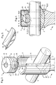
- Fig. 1 shows a perspective view of the inventive fastener, which consists essentially of a bone anchored lower portion 2 and a in Direction of the longitudinal axis 1 of the fastener subsequent thereto, upper section 3 consists.
- the lower portion 2 may be formed as a screw shaft or as a bent blade; in the first case, a so-called pedicle screw results in the second case, a spinal hook.
- the upper portion 3 has an upwardly open, transversely to the longitudinal axis 1 extending through channel 4, whereby a U-shaped receptacle with two opposite legs 26 and a bottom 18 is formed, in which the longitudinal member 5 can be easily inserted.
- the upper portion 3 further comprises a running in the direction of the longitudinal axis 1, a circular cylindrical, also open at the top blind hole 6. Inside the blind hole 6, ie on the inside of the two legs 26, an internal thread 11 is provided inside the blind hole 6, ie on the inside of the two legs 26, an internal thread 11 is provided inside the blind hole 6, ie on the inside of the two legs 26, an internal thread 11 is provided inside the blind hole 6, ie on the inside of the two legs 26, an internal thread 11 is provided inside the blind hole 6, ie on the inside of the two legs 26, an internal thread 11 is provided inside the blind hole 6, ie on the inside of the two legs 26, an internal thread 11 is provided inside the blind hole 6, ie on the inside of the two legs 26, a circular cylindrical fixation element 7 is provided
- the fixation element 7 has at its lower end 8 intended to bear against the longitudinal member 5 a spherical segment-shaped cavity 9, in which a ball 10 is rotatably fitted, which protrudes partially from the cavity 9.
- the fixation element 7 has a polygonal bore 17 extending in the direction of the longitudinal axis 1, into which a suitable, positive-locking instrument, in which For example, a hex key is insertable to screw the fixation element 7 in the internal thread 11 between the two legs 26 and to clamp against the side member 5 can.
- a further embodiment of the inventive fastener is shown, in which instead of a full ball only a ball part 25, namely a ball layer is provided.
- the ball part 25 is either flat or provided with a concave, lying perpendicular to its radius, circular cylindrical cutout 13 for positive engagement with the longitudinal member 5.
- the concave surface 13 is naturally adapted to the surface geometry of the longitudinal beam 5 to be used, i. it must have the same curvature in order to obtain an optimum effect, which is that a permanent contact surface between the surface 13 of the ball member 25 and the side member 5 is made.
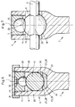
- FIGS. 3-5 show a further variant of the fastening element according to the invention, in which the bottom 18 of the blind hole 6 has a concave, circular cylindrical surface whose cylinder axis 19 extends perpendicular to the longitudinal axis 1 and through the center 20 of the ball part 25.
- An additional, insertable between the bottom 18 and the longitudinal member 5 tilting element 21 allows a coaxial rotation simultaneously with the ball member 25.
- the tilting member 21, which is shown in detail in Fig. 4, has a corresponding to the surface of the blind hole 18, convex surface 22nd and on the other hand, one to the surface of the longitudinal member. 5 corresponding, concave, circular cylindrical surface 23, the cylinder axis 24 is perpendicular to the cylinder axis 19.
- the center of rotation of the tilting element 21 is identical to the center 20 of the spherical cavity 9 in the fixation element 7 when the fixation element 7 is tightened.
- Fig. 6 shows a further variant of the inventive fastening element, wherein the bottom of the blind hole 18 of the upper portion 3 is provided in the direction of the passage channel 4 with wedge-shaped gradations 27; Accordingly, the outer longitudinal sides 28 of the tilting element 21 are also wedge-shaped.
- the concave surface 23 of the tilting element 21 is provided with a longitudinal toothing 29, which corresponds to a corresponding longitudinal toothing 30 of the longitudinal member 5, so that after successful tightening of the fixation element 7, the longitudinal member 5 is secured against rotation.
- the upper portion 3 has a over the two legs 26 inverted stabilizing sleeve 31 with a central bore 34, which secures the two legs 26 against a widening, as they may result when screwing and tightening the fixation element 7.
- a bore having an internal thread 32 and a transverse slot 33 for receiving a screwdriver-like instrument is provided.
- Such a design facilitates the introduction, the manipulation and the simultaneous tightening of the fixation element 7.
- FIG. 7 shows a further variant of the fastening element according to the invention, in which the ball part 25, here in the form of a spherical segment, has a concave spherical cutout 14 perpendicular to the radius of the ball part 25 for positive engagement with a spherical one which can be pushed onto the side rail 5 Cuff 15 is provided.
- the sleeve 15 has a central bore with a slot 29 to allow a resilient attachment to the side member 5.
- the spherical surface of the cuff 25 and the concave cutout 14 must be matched to each other, i. have the same curvature.
Abstract
Description
- Die Erfindung bezieht sich auf ein osteosynthetisches Befestigungselement, insbesondere eine Pedikelschraube oder einen Wirbelsäulenhaken gemäss der Gattung des Patentanspruchs 1.
- Aus der DE-U1 89.15.443.6 ist bereits ein Befestigungselement dieser Gattung, insbesondere für die Wirbelsäulenchirurgie bekannt. Es besteht im wesentlichen aus einem am Knochen verankerbaren unteren Teil in Form eines Schraubenschaftes oder einer Klinge und einem daran anschliessenden, oberen Körper zur Befestigung an einer Stange, wobei in dem Körper ein nach oben mündender Kanal ausgebildet ist, der zwei seitliche Schenkel begrenzt, zwischen denen die Stange aufgenommen werden kann. Die Fixation der Stange innerhalb des Kanals erfolgt durch einen von oben zwischen die Schenkel einschraubbaren Gewindestopfen, dessen unteres, zur Anlage an die Stange bestimmtes Ende mit Verhakungsmitteln in Form einer oder mehrerer Spitzen versehen ist.
Die beim Eindrehen des Gewindestopfens zwischen die beiden Schenkel des Körpers an der darin liegenden Stange zur Anlage kommenden Spitzen graben sich punktuell in die Oberfläche der Stange ein und bewirken eine gewisse Fixierung der Stange relativ zum Körper. Nachteilig bei dieser Konstruktion ist der bloss punktuelle Kontakt zwischen Stange und Gewindestopfen, der sich leicht lockern kann, wenn Kräfte zwischen Stange und Befestigungselement zur Wirkung kommen, was im Wirbelsäulenbereich die Regel ist. Die langen Hebelarme mit denen an der Stange angreifende Kräfte auf die bloss punktuellen Verhakungen wirken, führen auch bei geringsten Kraftbeträgen zu einer raschen und irreversiblen Lockerung der Fixation. - Hier will die Erfindung für Abhilfe sorgen. Der Erfindung liegt die Aufgabe zugrunde, ein osteosynthetisches Befestigungselement der beschriebenen Gattung zu schaffen, welches bei auftretenden Kräften die Verklemmung aufrecht erhalten kann oder gar einen selbstklemmenden Effekt erzeugen kann, so dass eine Lockerung der aneinander befestigten Elemente verhindert wird.
- Die Erfindung löst die gestellte Aufgabe mit einem Befestigungselement, welches die Merkmale des Anspruchs 1 aufweist.
- Bei der Erfindung ist das untere Ende des Fixationselementes mit einer, vorzugsweise beweglich in einer Aushöhlung angeordneten Kugel versehen, die teilweise daraus hervorragt. Gegenüber den aus dem Stand der Technik bekannten Fixationselementen, insbesondere deren unteres Ende, hat diese Konstruktion den Vorteil, dass sie sich bei allfällig auftretenden Relativbewegungen zwischen den befestigten Elementen selbsttätig adaptieren kann ohne eine Lockerung zu bewirken. Innerhalb relativ breiter Grenzen bewirkt eine Relativbewegung zwischen Längsträger und Befestigungselement keine Lockerung. Dank der abrollbaren Kugelgeometrie kann eine bleibende, konstante Klemmung aufrecht erhalten werden.
- Vorzugsweise ist die Kugel bloss als Kugelsegment oder Kugelschicht ausgebildet, damit statt einer bloss punktuellen eine lineare Auflage und Verklemmung erzielt werden kann.
- Ist die Kugel oder der Kugelteil beweglich ausgebildet, so versucht sich dieser bei einer allfällig auftretenden Translation zwischen Kugel(teil) und Längsträger aufgrund der Reibungskraft zu drehen, was zu einer Verkantung und damit sogar zu einer Erhöhung der Verklemmung führt.
- Eine weitere Verbesserung kann erzielt werden, indem das Kugelteil mit einer konkaven, senkrecht zum Radius des Kugelteils liegenden, kreiszylindrischen Ausfräsung zur formschlüssigen Anlage an den Längsträger versehen wird. Damit kann ein dauerhafter Flächenkontakt erzielt werden.
- Bei einer weiteren Ausführungsform der Erfindung ist das Kugelteil mit einer konkaven, senkrecht zum Radius des Kugelteils liegenden, sphärischen Ausfräsung zur formschlüssigen Anlage an eine auf den Längsträger aufschiebbare sphärische Manschette versehen. Wenn sich die sphärische Manschette - aufgrund einer am Längsträger angreifenden Kraft - in irgend eine Richtung drehen will, so versucht sich der Kugelteil mit der sphärischen Ausfräsung aufgrund der Reibung in die entgegengesetzte Richtung zu drehen, was wiederum zu einer Erhöhung der Klemmwirkung führt.
- Eine weitere Verbesserung der Wirkung des erfindungsgemässen Befestigungselementes kann dadurch erzielt werden, dass auch die untere Auflage des Längsträgers auf dem Boden des Durchgangskanals adaptierbar gestaltet wird. Zu diesem Zweck ist der Boden des Sackloches mit einer konkaven, kreiszylinderförmigen Oberfläche ausgebildet, deren Zylinderachse senkrecht zur Längsachse und durch das Zentrum der Kugel verläuft. Zwischen dem Boden und dem Längsträger kann nun ein Kippelement eingelegt werden, welches einerseits eine zur Oberfläche des Sackloches korrespondierende, konvexe Oberfläche und anderseits eine zur Oberfläche des Längsträgers korrespondierende, konkave, kreiszylinderförmige Oberfläche aufweist, deren Zylinderachse senkrecht dazu verläuft. Mittels dieses zusätzlichen Kippelementes, welches um die gleiche Achse wie die Kugel rotieren kann, ist innerhalb eines erheblichen Winkelbereiches eine vollständige Adaptation an allfällig auftretende Winkeländerungen zwischen Längsträger und Befestigungselement möglich, ohne dass dabei die Verklemmung zwischen den einzelnen Elementen gelockert wird.
Bei dieser Ausführung wird der Boden des Sackloches vorzugsweise strukturiert ausgebildet, z.B. in Form einer Verzahnung oder durch eine keilförmige Geometrie. Auch die konvexe Oberfläche des Kippelementes kann analog strukturiert werden. Bevorzugte Kombinationen der beiden aneinander zur Anlage kommenden Oberflächen sind die folgenden:Kippelement Sacklochboden - verzahnt / hartes Material - glatt / weiches Material - glatt / weiches Material - verzahnt / hartes Material - verzahnt - verzahnt - keilförmige Geometrie der Längsseiten - keilförmige Geometrie der Längsseiten - Vorzugsweise ist der Durchgangskanal nach oben offen ausgebildet, derart dass der obere Abschnitt eine U-förmige Aufnahme mit zwei seitlichen Schenkeln für den Längsträger bildet. Bei dieser Ausführungsform werden die beiden Schenkel vorteilhafterweise mittels einer Stabilisierungshülse gesichert, da die beiden Schenkel beim Eindrehen des Fixationselementes die Neigung haben sich zu öffnen. Für spezielle Anwendung kann der Durchgangskanal aber auch oben geschlossen bleiben, so dass keine Stabilisierungshülse nötig ist.
- Ausführungsbeispiele der Erfindung, welche zugleich das Funktionsprinzip erläutern, sind in der Zeichnung dargestellt und werden im folgenden näher beschrieben.
- Fig. 1 stellt eine perspektivische Darstellung des erfindungsgemässen Befestigungselementes mit einer Kugel als wesentlichem Fixationselement dar;
- Fig. 2 stellt eine perspektivische Darstellung einer Ausführungsform mit einem Kugelteil als wesentlichem Fixationselement dar;
- Fig. 3 stellt eine perspektivische Darstellung einer Ausführungsform mit einem zusätzlichen Kippelement dar;
- Fig. 4 stellt einen teilweisen Längsschnitt durch das geschlossene Fixationselement nach Fig. 3 dar;
- Fig. 5 stellt eine perspektivische Darstellung des Kippelementes nach Fig. 3 dar;
- Fig. 6 stellt einen Querschnitt durch eine weitere Ausführungsform der Erfindung mit einer zusätzlichen Stabilisierungshülse dar; und
- Fig. 7 stellt einen teilweisen Längsschnitt durch eine weitere Ausführungsform mit zusätzlicher Manschette für den Längsträger dar.
- Fig. 1 zeigt eine perspektivische Darstellung des erfindungsgemässen Befestigungselementes, welches im wesentlichen aus einem am Knochen verankerbaren unteren Abschnitt 2 und einem in Richtung der Längsachse 1 des Befestigungselementes daran anschliessenden, oberen Abschnitt 3 besteht. Der untere Abschnitt 2 kann als Schraubenschaft oder als abgebogene Klinge ausgebildet sein; im ersten Fall ergibt sich eine sogenannte Pedikelschraube im zweiten Fall ein Wirbelsäulenhaken.
- Der obere Abschnitt 3 weist einen nach oben offenen, quer zur Längsachse 1 verlaufenden Durchgangskanal 4 auf, wodurch eine U-förmige Aufnahme mit zwei gegenüberliegenden Schenkeln 26 und einem Boden 18 gebildet wird, in welche der Längsträger 5 bequem eingeführt werden kann. Der obere Abschnitt 3 weist ferner ein in Richtung der Längsachse 1 verlaufendes, kreiszylindrisches, ebenfalls nach oben offenes Sackloch 6 auf. Im Inneren des Sackloches 6, d.h. an der Innenseite der beiden Schenkel 26, ist ein Innengewinde 11 vorgesehen. Zur Verschliessung des Sackloches 6 und Verklemmung des Längsträger 5 zwischen den beiden Schenkeln 26 ist ein kreiszylindrisches Fixationselement 7 vorgesehen, welches ein mit dem Innengewinde 11 korrespondierendes Aussengewinde 12 trägt.
Das Fixationselement 7 weist an seinem unteren, zur Anlage am Längsträger 5 bestimmten Ende 8 eine kugelsegmentförmige Aushöhlung 9 auf, in welcher eine Kugel 10 drehbar eingepasst ist, die teilweise aus der Aushöhlung 9 herausragt. An seinem oberen Ende 16 weist das Fixationselement 7 eine in Richtung der Längsachse 1 verlaufende, polygonale Bohrung 17 auf, in welche ein geeignetes, formschlüssiges Instrument, z.B. ein Sechskantschlüssel einführbar ist, um das Fixationselement 7 in das Innengewinde 11 zwischen den beiden Schenkeln 26 eindrehen und gegen den Längsträger 5 festklemmen zu können. - In Fig. 2 ist eine weitere Ausführungsform des erfindungsgemässen Befestigungselementes dargestellt, bei der statt einer vollen Kugel bloss ein Kugelteil 25, nämlich eine Kugelschicht vorgesehen ist. Das Kugelteil 25 ist entweder flach ausgebildet oder mit einer konkaven, senkrecht zu seinem Radius liegenden, kreiszylindrischen Ausfräsung 13 zur formschlüssigen Anlage an den Längsträger 5 versehen. Die konkave Oberfläche 13 ist naturgemäss an die Oberflächengeometrie des zu verwendenden Längsträgers 5 anzupassen, d.h. sie muss die gleiche Krümmung aufweisen um einen optimalen Effekt zu erzielen, der darin besteht, dass eine dauerhafte Kontaktfläche zwischen der Oberfläche 13 des Kugelteils 25 und dem Längsträger 5 hergestellt wird.
- Die Fig. 3 - 5 zeigen eine weitere Variante des erfindungsgemässen Befestigungselementes, bei welcher der Boden 18 des Sackloches 6 eine konkave, kreiszylinderförmige Oberfläche aufweist, deren Zylinderachse 19 senkrecht zur Längsachse 1 und durch das Zentrum 20 des Kugelteils 25 hindurch verläuft. Ein zusätzliches, zwischen dem Boden 18 und dem Längsträger 5 einlegbares Kippelement 21 erlaubt eine koaxiale Rotation gleichzeitig mit dem Kugelteil 25. Das Kippelement 21, welches im Detail in Fig. 4 dargestellt ist, weist eine zur Oberfläche des Sackloches 18 korrespondierende, konvexe Oberfläche 22 und anderseits eine zur Oberfläche des Längsträgers 5 korrespondierende, konkave, kreiszylinderförmige Oberfläche 23 auf, deren Zylinderachse 24 senkrecht zur Zylinderachse 19 verläuft. Das Rotationszentrum des Kippelementes 21 ist identisch mit dem Zentrum 20 der kugeligen Aushöhlung 9 im Fixationselement 7, wenn das Fixationselement 7 angezogen ist.
- Fig. 6 zeigt eine weitere Variante des erfindungsgemässen Befestigungselementes, bei welcher der Boden des Sackloches 18 des oberen Abschnitts 3 in Richtung des Durchgangskanals 4 mit keilförmigen Abstufungen 27 versehen ist; dementsprechend sind die äusseren Längsseiten 28 des Kippelementes 21 ebenfalls keilförmig ausgebildet.
Die konkave Oberfläche 23 des Kippelementes 21 ist mit einer Längszähnung 29 versehen, welche mit einer entsprechenden Längszähnung 30 des Längsträgers 5 korrespondiert, so dass nach erfolgtem Anziehen des Fixationselementes 7 der Längsträger 5 gegen Verdrehung gesichert ist.
Schliesslich weist der obere Abschnitt 3 eine über die beiden Schenkel 26 stülpbare Stabilisierungshülse 31 mit einer zentralen Bohrung 34 auf, welche die beiden Schenkel 26 gegen eine Aufweitung, wie sie sich beim Eindrehen und Anziehen des Fixationselementes 7 ergeben kann, sichert.
Statt einer polygonalen Bohrung 17 (Fig. 1 - 3) ist bei dieser Ausführungsform eine Bohrung mit Innengewinde 32 und einem Querschlitz 33 zur Aufnahme eines schraubenzieherähnlichen Instrumentes, vorgesehen. Eine solche Gestaltung erleichtert das Einbringen, die Manipulation und das simultane Anziehen des Fixationselementes 7. - Fig. 7 zeigt schliesslich eine weitere Variante des erfindungsgemässen Befestigungselementes, bei welcher das Kugelteil 25, hier in Form eines Kugelsegmentes, mit einer konkaven, senkrecht zum Radius des Kugelteils 25 liegenden, sphärischen Ausfräsung 14 zur formschlüssigen Anlage an eine auf den Längsträger 5 aufschiebbare sphärische Manschette 15 versehen ist. Die Manschette 15 weist eine zentrale Bohrung mit einem Schlitz 29 auf um ein federndes Aufstecken auf dem Längsträger 5 zu gestatten. Auch bei dieser Ausführungsform müssen die sphärische Oberfläche der Manschette 25 und die konkave Ausfräsung 14 aufeinander abgestimmt sein, d.h. die gleiche Krümmung aufweisen.
Claims (13)
- Osteosynthetisches Befestigungselement, insbesondere Pedikelschraube oder Wirbelsäulenhaken, mit einer Längsachse (1), mit einem am Knochen verankerbaren unteren Abschnitt (2) und einem in Richtung der Längsachse (1) daran anschliessenden, oberen Abschnitt (3), welcher von einem quer zur Längsachse (1) verlaufenden Durchgangskanal (4) zur Aufnahme eines Längsträgers (5) vollständig durchquert ist, und welcher ein in Richtung der Längsachse (1) verlaufendes, kreiszylindrisches, nach oben offenes Sackloch (6) zur kraftschlüssigen Aufnahme eines damit korrespondierenden, kreiszylindrischen Fixationselementes (7) für den Längsträger (5) aufweist, dadurch gekennzeichnet, dass das Fixationselement (7) an seinem unteren, zur Anlage am Längsträger (5) bestimmten Ende (8) eine kugelsegmentförmige Aushöhlung (9) aufweist, in welcher eine Kugel (10) eingepasst ist, die teilweise aus der Aushöhlung (9) herausragt.
- Befestigungselement nach Anspruch 1, dadurch gekennzeichnet, dass das Sackloch (6) mit einem Innengewinde (12) und das Fixationselement (7) mit einem damit korrespondierenden Aussengewinde (12) versehen ist.
- Befestigungselement nach Anspruch 1 oder 2, dadurch gekennzeichnet, dass die Kugel (10) drehbar in der Aushöhlung (9) gelagert ist.
- Befestigungselement nach einem der Ansprüche 1 - 3, dadurch gekennzeichnet, dass die Kugel (10) als Kugelteil (25), vorzugsweise als Kugelsegment oder Kugelschicht ausgebildet ist.
- Befestigungselement nach Anspruch 4, dadurch gekennzeichnet, dass das Kugelteil (25) mit einer konkaven, senkrecht zum Radius des Kugelteils (25) liegenden, kreiszylindrischen Ausfräsung (13) zur formschlüssigen Anlage an den Längsträger (5) versehen ist.
- Befestigungselement nach Anspruch 4, dadurch gekennzeichnet, dass das Kugelteil (25) mit einer konkaven, senkrecht zum Radius des Kugelteils (25) liegenden, sphärischen Ausfräsung (14) zur formschlüssigen Anlage an eine auf den Längsträger (5) aufschiebbare sphärische Manschette (15) versehen ist.
- Befestigungselement nach einem der Ansprüche 1 bis 6, dadurch gekennzeichnet, dass das Fixationselement (7) an seinem oberen Ende (16) eine in Richtung der Längsachse (1) verlaufende, polygonale Bohrung (17) zur formschlüssigen Aufnahme eines Instrumentes aufweist.
- Befestigungselement nach einem der Ansprüche 1 bis 6, dadurch gekennzeichnet, dass das Fixationselement (7) an seinem oberen Ende (16) einen quer zur Längsachse (1) verlaufenden Schlitz (33) mit einer zentralen Bohrung mit Innengewinde (32) zur formschlüssigen Aufnahme eines Instrumentes aufweist.
- Befestigungselement nach einem der Ansprüche 1 bis 8, dadurch gekennzeichnet, dassA) der Boden (18) des Sackloches (6) eine konkave, kreiszylinderförmige Oberfläche aufweist, deren Zylinderachse (19) senkrecht zur Längsachse (1) und durch das Zentrum (20) der Kugel (10) oder des Kugelteils (25) verläuft, undB) ein zusätzliches, zwischen dem Boden (18) und dem Längsträger (5) einlegbares Kippelement (21) vorgesehen ist, welches einerseits eine zur Oberfläche des Sackloches (18) korrespondierende, konvexe Oberfläche (22) und anderseits eine zur Oberfläche des Längsträgers (5) korrespondierende, konkave, kreiszylinderförmige Oberfläche (23) aufweist, deren Zylinderachse (24) senkrecht zur Zylinderachse (19) verläuft.
- Befestigungselement nach einem der Ansprüche 1 bis 9, dadurch gekennzeichnet, dass der Boden (18) des Sackloches (6) sowie die konvexe Oberfläche (22) des Kippelementes (21) strukturiert, vorzugsweise mit einer Verzahnung, ausgebildet sind.
- Befestigungselement nach einem der Ansprüche 1 bis 10, dadurch gekennzeichnet, dass die konkave Oberfläche (23) des Kippelementes (21) sowie die Oberfläche des Längsträgers (5) strukturiert, vorzugsweise mit einer Verzahnung (29,30), ausgebildet sind.
- Befestigungselement nach einem der Ansprüche 1 bis 11, dadurch gekennzeichnet, dass der Durchgangskanal (4) nach oben offen ausgebildet ist, derart, dass der obere Abschnitt (3) eine U-förmige Aufnahme für den Längsträger (5) bildet.
- Befestigungselement nach einem der Ansprüche 1 bis 12, dadurch gekennzeichnet, dass zusätzlich eine, vorzugsweise eine zentrale Bohrung (34) aufweisende Stabilisierungshülse (31) vorgesehen ist, welche formschlüssig auf die beiden Schenkel (27) stülpbar ist.
Applications Claiming Priority (2)
| Application Number | Priority Date | Filing Date | Title |
|---|---|---|---|
| CH179992 | 1992-06-04 | ||
| CH799/92 | 1992-06-04 |
Publications (2)
| Publication Number | Publication Date |
|---|---|
| EP0572790A1 true EP0572790A1 (de) | 1993-12-08 |
| EP0572790B1 EP0572790B1 (de) | 1996-02-14 |
Family
ID=4218877
Family Applications (1)
| Application Number | Title | Priority Date | Filing Date |
|---|---|---|---|
| EP19930106520 Expired - Lifetime EP0572790B1 (de) | 1992-06-04 | 1993-04-22 | Osteosynthetisches Befestigungselement |
Country Status (6)
| Country | Link |
|---|---|
| US (1) | US5520689A (de) |
| EP (1) | EP0572790B1 (de) |
| JP (1) | JP2561611B2 (de) |
| CA (1) | CA2097623C (de) |
| DE (1) | DE59301618D1 (de) |
| ES (1) | ES2085673T3 (de) |
Cited By (16)
| Publication number | Priority date | Publication date | Assignee | Title |
|---|---|---|---|---|
| FR2718943A1 (fr) * | 1994-04-21 | 1995-10-27 | Jbs Sa | Barre renforcée à trois branches pour ostéosynthèse du rachis. |
| FR2720923A1 (fr) * | 1994-06-10 | 1995-12-15 | Sra Sarl | Vis pour ostéosynthèse. |
| DE19605640A1 (de) * | 1996-02-15 | 1997-08-21 | Plus Endoprothetik Ag | Osteosynthetisches Befestigungselement |
| DE29810798U1 (de) * | 1998-06-17 | 1999-10-28 | Schaefer Micomed Gmbh | Osteosynthesevorrichtung |
| DE19829699A1 (de) * | 1998-07-02 | 2000-01-20 | Med Medical Engineering Dev Lt | Osteosynthetische Befestigungsvorrichtung |
| FR2786088A1 (fr) | 1998-11-24 | 2000-05-26 | Dimso Sa | Dispositif d'osteosynthese rachidienne a bague de serrage |
| KR100346308B1 (ko) * | 1999-11-02 | 2002-07-27 | 김성곤 | 척추경 나사못 |
| FR2833151A1 (fr) * | 2001-12-12 | 2003-06-13 | Ldr Medical | Implant d'ancrage osseux a tete polyaxiale |
| WO2005030065A1 (de) | 2003-09-26 | 2005-04-07 | Synthes Gmbh | Vorrichtung zur verbindung eines längsträgers mit einem knochen |
| EP1604617A1 (de) * | 2004-06-08 | 2005-12-14 | A-Spine Holding Group Corp. | Drehbare Vorrichtung zur Wiederherstellung einer Wirbelsäule in Behandlung |
| WO2008027853A2 (en) * | 2006-08-29 | 2008-03-06 | Warsaw Orthopedic, Inc | Orthopaedic screw system with linear motion |
| CN1931105B (zh) * | 2005-09-13 | 2012-09-05 | 伯德比德尔曼股份公司 | 用于脊柱植入物的动态夹紧装置 |
| US10299839B2 (en) | 2003-12-16 | 2019-05-28 | Medos International Sárl | Percutaneous access devices and bone anchor assemblies |
| US10314624B2 (en) | 2005-03-04 | 2019-06-11 | DePuy Synthes Products, Inc. | Instruments and methods for manipulating vertebra |
| US10751187B2 (en) | 2007-06-08 | 2020-08-25 | Ldr Medical | Intersomatic cage, intervertebral prosthesis, anchoring device and implantation instruments |
| US11419642B2 (en) | 2003-12-16 | 2022-08-23 | Medos International Sarl | Percutaneous access devices and bone anchor assemblies |
Families Citing this family (208)
| Publication number | Priority date | Publication date | Assignee | Title |
|---|---|---|---|---|
| US6077262A (en) * | 1993-06-04 | 2000-06-20 | Synthes (U.S.A.) | Posterior spinal implant |
| FR2731344B1 (fr) * | 1995-03-06 | 1997-08-22 | Dimso Sa | Instrumentation rachidienne notamment pour tige |
| US5702399A (en) * | 1996-05-16 | 1997-12-30 | Pioneer Laboratories, Inc. | Surgical cable screw connector |
| US5797911A (en) * | 1996-09-24 | 1998-08-25 | Sdgi Holdings, Inc. | Multi-axial bone screw assembly |
| US6248105B1 (en) * | 1997-05-17 | 2001-06-19 | Synthes (U.S.A.) | Device for connecting a longitudinal support with a pedicle screw |
| DE29710484U1 (de) * | 1997-06-16 | 1998-10-15 | Howmedica Gmbh | Aufnahmeteil für ein Haltebauteil eines Wirbelsäulenimplantats |
| DE19826380B4 (de) * | 1998-06-12 | 2005-09-22 | Aesculap Ag & Co. Kg | Osteosynthetisches Befestigungssystem |
| ES2153287B1 (es) * | 1998-06-16 | 2001-08-01 | Parrado Ruiz Araceli | Implante para el tratamiento de las patologias propias de la comuna vertebral. |
| US6565565B1 (en) | 1998-06-17 | 2003-05-20 | Howmedica Osteonics Corp. | Device for securing spinal rods |
| ES2154227B1 (es) * | 1999-06-30 | 2001-11-16 | Surgival Co S A | Sistema poliaxial de fijacion de vertebras. |
| US6616664B2 (en) | 1999-10-21 | 2003-09-09 | Ebi L.P. | Clamp assembly for an external fixation system |
| US6277119B1 (en) | 1999-10-21 | 2001-08-21 | Electro-Biology, Inc. | External fixation system |
| KR200200582Y1 (ko) * | 2000-03-15 | 2000-10-16 | 최길운 | 접골용 보철구 |
| JP2001314416A (ja) * | 2000-05-10 | 2001-11-13 | Showa Ika Kohgyo Co Ltd | 骨接合具用のロッド |
| US6899713B2 (en) | 2000-06-23 | 2005-05-31 | Vertelink Corporation | Formable orthopedic fixation system |
| CA2692387C (en) * | 2000-06-23 | 2011-02-22 | University Of Southern California | Percutaneous vertebral fusion system |
| US6749614B2 (en) | 2000-06-23 | 2004-06-15 | Vertelink Corporation | Formable orthopedic fixation system with cross linking |
| US6964667B2 (en) * | 2000-06-23 | 2005-11-15 | Sdgi Holdings, Inc. | Formed in place fixation system with thermal acceleration |
| US6875212B2 (en) * | 2000-06-23 | 2005-04-05 | Vertelink Corporation | Curable media for implantable medical device |
| ATE438347T1 (de) * | 2000-07-28 | 2009-08-15 | Synthes Gmbh | Spinales befestigungssystem |
| US6524315B1 (en) | 2000-08-08 | 2003-02-25 | Depuy Acromed, Inc. | Orthopaedic rod/plate locking mechanism |
| DE50106374D1 (de) * | 2000-09-18 | 2005-07-07 | Zimmer Gmbh Winterthur | Pedikelschraube für intervertebrale Stützelemente |
| EP1188416B1 (de) * | 2000-09-18 | 2005-06-01 | Zimmer GmbH | Pedikelschraube für intervertebrale Stützelemente |
| JP2002095672A (ja) | 2000-09-22 | 2002-04-02 | Showa Ika Kohgyo Co Ltd | 骨接合用具及びその連結部材 |
| US6755829B1 (en) | 2000-09-22 | 2004-06-29 | Depuy Acromed, Inc. | Lock cap anchor assembly for orthopaedic fixation |
| JP2002095674A (ja) | 2000-09-22 | 2002-04-02 | Showa Ika Kohgyo Co Ltd | 環軸関節固定用のフックケーブル及び固定用システム |
| US6620164B2 (en) | 2000-09-22 | 2003-09-16 | Showa Ika Kohgyo Co., Ltd. | Rod for cervical vertebra and connecting system thereof |
| US6702815B2 (en) | 2000-12-01 | 2004-03-09 | Charles Kuntz | Method and device to correct instability of hinged joints |
| US6663631B2 (en) | 2000-12-01 | 2003-12-16 | Charles A. Kuntz | Method and device to correct instability of hinge joints |
| KR100433833B1 (ko) * | 2001-04-06 | 2004-05-31 | 삼성테크윈 주식회사 | 척추용 고정 장치 |
| KR100433834B1 (ko) * | 2001-04-06 | 2004-05-31 | 삼성테크윈 주식회사 | 척추용 고정 장치 |
| FR2823095B1 (fr) * | 2001-04-06 | 2004-02-06 | Ldr Medical | Dispositif d'osteosynthese du rachis et procede de mise en place |
| US7722645B2 (en) * | 2001-09-24 | 2010-05-25 | Bryan Donald W | Pedicle screw spinal fixation device |
| FR2831049B1 (fr) | 2001-10-18 | 2004-08-13 | Ldr Medical | Plaque pour dispositif d'osteosynthese et procede de premontage |
| FR2831048B1 (fr) | 2001-10-18 | 2004-09-17 | Ldr Medical | Dispositif d'osteosynthese a approche progressive et procede de premontage |
| US6641586B2 (en) | 2002-02-01 | 2003-11-04 | Depuy Acromed, Inc. | Closure system for spinal fixation instrumentation |
| US7658582B2 (en) * | 2003-07-09 | 2010-02-09 | Ortho Innovations, Llc | Precise linear fastener system and method for use |
| US6660006B2 (en) * | 2002-04-17 | 2003-12-09 | Stryker Spine | Rod persuader |
| US6740086B2 (en) * | 2002-04-18 | 2004-05-25 | Spinal Innovations, Llc | Screw and rod fixation assembly and device |
| JP4047112B2 (ja) * | 2002-09-12 | 2008-02-13 | 昭和医科工業株式会社 | 椎骨連結部材のロッド部固定構造 |
| IL190642A (en) * | 2002-11-13 | 2011-06-30 | Biomet 3I Llc | Dental implant system |
| DE10256095B4 (de) * | 2002-12-02 | 2004-11-18 | Biedermann Motech Gmbh | Element mit einem Schaft und einem damit verbundenen Halteelement zum Verbinden mit einem Stab |
| US20040111088A1 (en) | 2002-12-06 | 2004-06-10 | Picetti George D. | Multi-rod bone attachment member |
| US7175624B2 (en) | 2002-12-31 | 2007-02-13 | Depuy Spine, Inc. | Bone plate and screw system allowing bi-directional assembly |
| US7914561B2 (en) * | 2002-12-31 | 2011-03-29 | Depuy Spine, Inc. | Resilient bone plate and screw system allowing bi-directional assembly |
| US6843791B2 (en) * | 2003-01-10 | 2005-01-18 | Depuy Acromed, Inc. | Locking cap assembly for spinal fixation instrumentation |
| US7887539B2 (en) | 2003-01-24 | 2011-02-15 | Depuy Spine, Inc. | Spinal rod approximators |
| US7341591B2 (en) * | 2003-01-30 | 2008-03-11 | Depuy Spine, Inc. | Anterior buttress staple |
| US7141051B2 (en) * | 2003-02-05 | 2006-11-28 | Pioneer Laboratories, Inc. | Low profile spinal fixation system |
| US7473267B2 (en) * | 2003-04-25 | 2009-01-06 | Warsaw Orthopedic, Inc. | System and method for minimally invasive posterior fixation |
| US7377923B2 (en) * | 2003-05-22 | 2008-05-27 | Alphatec Spine, Inc. | Variable angle spinal screw assembly |
| FR2859095B1 (fr) | 2003-09-01 | 2006-05-12 | Ldr Medical | Implant d'ancrage osseux a tete polyaxiale et procede de mise en place de l'implant |
| AU2003258438B2 (en) * | 2003-09-08 | 2009-07-09 | Synthes Gmbh | Longitudinal support |
| FR2860138A1 (fr) * | 2003-09-26 | 2005-04-01 | Stryker Spine | Assemblage et procede de fixation d'os |
| US7588588B2 (en) * | 2003-10-21 | 2009-09-15 | Innovative Spinal Technologies | System and method for stabilizing of internal structures |
| US7967826B2 (en) * | 2003-10-21 | 2011-06-28 | Theken Spine, Llc | Connector transfer tool for internal structure stabilization systems |
| US7588575B2 (en) * | 2003-10-21 | 2009-09-15 | Innovative Spinal Technologies | Extension for use with stabilization systems for internal structures |
| US20050247169A1 (en) * | 2003-11-26 | 2005-11-10 | Faries Durward I Jr | Fastening system and method of fastening objects with enhanced security |
| US8029548B2 (en) * | 2008-05-05 | 2011-10-04 | Warsaw Orthopedic, Inc. | Flexible spinal stabilization element and system |
| US7862594B2 (en) * | 2004-02-27 | 2011-01-04 | Custom Spine, Inc. | Polyaxial pedicle screw assembly |
| US7789896B2 (en) * | 2005-02-22 | 2010-09-07 | Jackson Roger P | Polyaxial bone screw assembly |
| US7819902B2 (en) * | 2004-02-27 | 2010-10-26 | Custom Spine, Inc. | Medialised rod pedicle screw assembly |
| US7892257B2 (en) | 2004-02-27 | 2011-02-22 | Custom Spine, Inc. | Spring loaded, load sharing polyaxial pedicle screw assembly and method |
| US7163539B2 (en) * | 2004-02-27 | 2007-01-16 | Custom Spine, Inc. | Biased angle polyaxial pedicle screw assembly |
| US20050216027A1 (en) * | 2004-03-24 | 2005-09-29 | Suh Sean S | Extraction screwdriver |
| US20050228380A1 (en) * | 2004-04-09 | 2005-10-13 | Depuy Spine Inc. | Instruments and methods for minimally invasive spine surgery |
| WO2005102195A1 (en) * | 2004-04-20 | 2005-11-03 | Allez Spine, Llc | Pedicle screw assembly |
| US7763049B2 (en) * | 2004-06-09 | 2010-07-27 | Zimmer Spine, Inc. | Orthopedic fixation connector |
| US7766945B2 (en) * | 2004-08-10 | 2010-08-03 | Lanx, Inc. | Screw and rod fixation system |
| DE202004020396U1 (de) | 2004-08-12 | 2005-07-07 | Columbus Trading-Partners Pos und Brendel GbR (vertretungsberechtigte Gesellschafter Karin Brendel, 95503 Hummeltal und Bohumila Pos, 95445 Bayreuth) | Kindersitz für Kraftfahrzeuge |
| US7186255B2 (en) * | 2004-08-12 | 2007-03-06 | Atlas Spine, Inc. | Polyaxial screw |
| US20060058787A1 (en) * | 2004-08-24 | 2006-03-16 | Stryker Spine | Spinal implant assembly |
| JP2008517733A (ja) | 2004-10-25 | 2008-05-29 | アルファスパイン インコーポレイテッド | ペディクルねじシステムおよび、該システムの組立/設置法 |
| US7604655B2 (en) * | 2004-10-25 | 2009-10-20 | X-Spine Systems, Inc. | Bone fixation system and method for using the same |
| US7569061B2 (en) | 2004-11-16 | 2009-08-04 | Innovative Spinal Technologies, Inc. | Off-axis anchor guidance system |
| US20060155283A1 (en) * | 2005-01-07 | 2006-07-13 | Depuy Spine Sarl | Occipital plate and guide systems |
| DE102005009282A1 (de) * | 2005-02-22 | 2006-08-24 | Aesculap Ag & Co. Kg | Implantatsystem und Befestigungselement für ein Implantatsystem |
| US7951172B2 (en) * | 2005-03-04 | 2011-05-31 | Depuy Spine Sarl | Constrained motion bone screw assembly |
| US7621942B2 (en) | 2005-03-21 | 2009-11-24 | Zimmer Spine, Inc. | Variable geometry occipital fixation plate |
| US7338491B2 (en) * | 2005-03-22 | 2008-03-04 | Spinefrontier Inc | Spinal fixation locking mechanism |
| US7628800B2 (en) * | 2005-06-03 | 2009-12-08 | Warsaw Orthopedic, Inc. | Formed in place corpectomy device |
| US8177823B2 (en) * | 2005-06-30 | 2012-05-15 | Depuy Spine Sarl | Orthopedic clamping hook assembly |
| US7717943B2 (en) | 2005-07-29 | 2010-05-18 | X-Spine Systems, Inc. | Capless multiaxial screw and spinal fixation assembly and method |
| KR100650208B1 (ko) * | 2005-08-05 | 2006-11-27 | 주식회사 엔에이치에스 | 척추고정장치 |
| CH705709B1 (de) * | 2005-08-29 | 2013-05-15 | Bird Biedermann Ag | Wirbelsäulenimplantat. |
| DE502006002049D1 (de) * | 2005-09-13 | 2008-12-24 | Bird Biedermann Ag | Dynamische Klemmvorrichtung für Wirbelsäulenimplantat |
| TW200722034A (en) * | 2005-09-30 | 2007-06-16 | Paradigm Spine Llc | Hinged polyaxial screw and methods of use |
| US7686835B2 (en) * | 2005-10-04 | 2010-03-30 | X-Spine Systems, Inc. | Pedicle screw system with provisional locking aspects |
| US8075599B2 (en) * | 2005-10-18 | 2011-12-13 | Warsaw Orthopedic, Inc. | Adjustable bone anchor assembly |
| US8002806B2 (en) * | 2005-10-20 | 2011-08-23 | Warsaw Orthopedic, Inc. | Bottom loading multi-axial screw assembly |
| US7722651B2 (en) | 2005-10-21 | 2010-05-25 | Depuy Spine, Inc. | Adjustable bone screw assembly |
| GB0521585D0 (en) * | 2005-10-22 | 2005-11-30 | Depuy Int Ltd | A spinal support rod |
| GB0521582D0 (en) * | 2005-10-22 | 2005-11-30 | Depuy Int Ltd | An implant for supporting a spinal column |
| EP1795134B1 (de) * | 2005-11-17 | 2008-08-06 | BIEDERMANN MOTECH GmbH | Polyaxialschraube für flexiblen Stab |
| US8100946B2 (en) | 2005-11-21 | 2012-01-24 | Synthes Usa, Llc | Polyaxial bone anchors with increased angulation |
| US8034078B2 (en) | 2008-05-30 | 2011-10-11 | Globus Medical, Inc. | System and method for replacement of spinal motion segment |
| KR200410476Y1 (ko) * | 2005-12-21 | 2006-03-07 | (주)베리안 | 척추경 나사못 |
| GB0600662D0 (en) * | 2006-01-13 | 2006-02-22 | Depuy Int Ltd | Spinal support rod kit |
| US8348952B2 (en) * | 2006-01-26 | 2013-01-08 | Depuy International Ltd. | System and method for cooling a spinal correction device comprising a shape memory material for corrective spinal surgery |
| US20070270813A1 (en) * | 2006-04-12 | 2007-11-22 | Laszlo Garamszegi | Pedicle screw assembly |
| US8361129B2 (en) * | 2006-04-28 | 2013-01-29 | Depuy Spine, Inc. | Large diameter bone anchor assembly |
| US20070299441A1 (en) * | 2006-06-09 | 2007-12-27 | Zachary M. Hoffman | Adjustable Occipital Plate |
| US8172882B2 (en) | 2006-06-14 | 2012-05-08 | Spartek Medical, Inc. | Implant system and method to treat degenerative disorders of the spine |
| US7665606B2 (en) * | 2006-06-16 | 2010-02-23 | Gaillard Johnnie M | Clamp-on tray for neurosurgical patties |
| WO2008008511A2 (en) * | 2006-07-14 | 2008-01-17 | Laszlo Garamszegi | Pedicle screw assembly with inclined surface seat |
| US8062340B2 (en) * | 2006-08-16 | 2011-11-22 | Pioneer Surgical Technology, Inc. | Spinal rod anchor device and method |
| ES2453196T3 (es) * | 2006-08-24 | 2014-04-04 | Biedermann Technologies Gmbh & Co. Kg | Dispositivo de anclaje óseo |
| EP1900334B2 (de) * | 2006-09-15 | 2013-01-16 | BIEDERMANN MOTECH GmbH | Knochenverankerungsvorrichtung |
| WO2008039790A1 (en) * | 2006-09-25 | 2008-04-03 | Zimmer Spine, Inc. | Apparatus for connecting a longitudinal member to a bone portion |
| US7918857B2 (en) | 2006-09-26 | 2011-04-05 | Depuy Spine, Inc. | Minimally invasive bone anchor extensions |
| US7901433B2 (en) | 2006-10-04 | 2011-03-08 | Zimmer Spine, Inc. | Occipito-cervical stabilization system and method |
| US7967821B2 (en) | 2006-11-20 | 2011-06-28 | Depuy Spine, Inc. | Break-off screw extension removal tools |
| US8147527B2 (en) * | 2006-11-28 | 2012-04-03 | Zimmer Spine, Inc. | Adjustable occipital plate |
| US8758407B2 (en) * | 2006-12-21 | 2014-06-24 | Warsaw Orthopedic, Inc. | Methods for positioning a load-bearing orthopedic implant device in vivo |
| US7771476B2 (en) | 2006-12-21 | 2010-08-10 | Warsaw Orthopedic Inc. | Curable orthopedic implant devices configured to harden after placement in vivo by application of a cure-initiating energy before insertion |
| US8480718B2 (en) * | 2006-12-21 | 2013-07-09 | Warsaw Orthopedic, Inc. | Curable orthopedic implant devices configured to be hardened after placement in vivo |
| US8663328B2 (en) * | 2006-12-21 | 2014-03-04 | Warsaw Orthopedic, Inc. | Methods for positioning a load-bearing component of an orthopedic implant device by inserting a malleable device that hardens in vivo |
| FR2910267B1 (fr) * | 2006-12-21 | 2009-01-23 | Ldr Medical Soc Par Actions Si | Dispositif de soutien vertebral |
| US8246662B2 (en) | 2006-12-27 | 2012-08-21 | Zimmer Spine, Inc. | Modular occipital plate |
| US8636737B2 (en) | 2006-12-27 | 2014-01-28 | Zimmer Spine, Inc. | Modular occipital plate |
| US20080161853A1 (en) * | 2006-12-28 | 2008-07-03 | Depuy Spine, Inc. | Spine stabilization system with dynamic screw |
| EP2117451A1 (de) * | 2006-12-29 | 2009-11-18 | Zimmer Spine Austin, Inc. | Wirbelsäulenstabilisierungssysteme und -verfahren |
| US8636783B2 (en) * | 2006-12-29 | 2014-01-28 | Zimmer Spine, Inc. | Spinal stabilization systems and methods |
| US8747445B2 (en) | 2007-01-15 | 2014-06-10 | Ebi, Llc | Spinal fixation device |
| US8029547B2 (en) * | 2007-01-30 | 2011-10-04 | Warsaw Orthopedic, Inc. | Dynamic spinal stabilization assembly with sliding collars |
| US8109975B2 (en) * | 2007-01-30 | 2012-02-07 | Warsaw Orthopedic, Inc. | Collar bore configuration for dynamic spinal stabilization assembly |
| EP2146654A4 (de) | 2007-03-27 | 2011-09-28 | X Spine Systems Inc | Stielschraubensystem zur aufnahme einer geraden oder gebogenen stange |
| US8465526B2 (en) | 2007-04-30 | 2013-06-18 | Globus Medical, Inc. | Flexible spine stabilization system |
| US8114134B2 (en) | 2007-06-05 | 2012-02-14 | Spartek Medical, Inc. | Spinal prosthesis having a three bar linkage for motion preservation and dynamic stabilization of the spine |
| US8083772B2 (en) | 2007-06-05 | 2011-12-27 | Spartek Medical, Inc. | Dynamic spinal rod assembly and method for dynamic stabilization of the spine |
| US8002800B2 (en) | 2007-06-05 | 2011-08-23 | Spartek Medical, Inc. | Horizontal rod with a mounting platform for a dynamic stabilization and motion preservation spinal implantation system and method |
| US8021396B2 (en) | 2007-06-05 | 2011-09-20 | Spartek Medical, Inc. | Configurable dynamic spinal rod and method for dynamic stabilization of the spine |
| US8048115B2 (en) | 2007-06-05 | 2011-11-01 | Spartek Medical, Inc. | Surgical tool and method for implantation of a dynamic bone anchor |
| US8048122B2 (en) | 2007-06-05 | 2011-11-01 | Spartek Medical, Inc. | Spine implant with a dual deflection rod system including a deflection limiting sheild associated with a bone screw and method |
| US8092501B2 (en) | 2007-06-05 | 2012-01-10 | Spartek Medical, Inc. | Dynamic spinal rod and method for dynamic stabilization of the spine |
| US7963978B2 (en) | 2007-06-05 | 2011-06-21 | Spartek Medical, Inc. | Method for implanting a deflection rod system and customizing the deflection rod system for a particular patient need for dynamic stabilization and motion preservation spinal implantation system |
| WO2008151096A1 (en) | 2007-06-05 | 2008-12-11 | Spartek Medical, Inc. | A deflection rod system for a dynamic stabilization and motion preservation spinal implantation system and method |
| US20090005815A1 (en) * | 2007-06-28 | 2009-01-01 | Scott Ely | Dynamic stabilization system |
| US9439681B2 (en) | 2007-07-20 | 2016-09-13 | DePuy Synthes Products, Inc. | Polyaxial bone fixation element |
| PL2170192T3 (pl) * | 2007-07-20 | 2011-07-29 | Synthes Gmbh | Wieloosiowy przyrząd do stabilizacji kości |
| EP2182871B1 (de) | 2007-07-26 | 2014-07-02 | Glenn R. Buttermann M. D. | Segmentale orthopädische vorrichtung zur streckung der wirbelsäule und zur behandlung von skoliose |
| US9204908B2 (en) * | 2007-07-26 | 2015-12-08 | Dynamic Spine, Llc | Segmental orthopedic device for spinal elongation and for treatment of scoliosis |
| US20090069849A1 (en) * | 2007-09-10 | 2009-03-12 | Oh Younghoon | Dynamic screw system |
| US8414588B2 (en) | 2007-10-04 | 2013-04-09 | Depuy Spine, Inc. | Methods and devices for minimally invasive spinal connection element delivery |
| GB0720762D0 (en) | 2007-10-24 | 2007-12-05 | Depuy Spine Sorl | Assembly for orthopaedic surgery |
| ES2373690T3 (es) * | 2007-12-13 | 2012-02-07 | Biedermann Motech Gmbh | Dispositivo de anclaje para anclar una varilla en un hueso o vértebra. |
| US9232968B2 (en) * | 2007-12-19 | 2016-01-12 | DePuy Synthes Products, Inc. | Polymeric pedicle rods and methods of manufacturing |
| US8007522B2 (en) | 2008-02-04 | 2011-08-30 | Depuy Spine, Inc. | Methods for correction of spinal deformities |
| US20100030224A1 (en) | 2008-02-26 | 2010-02-04 | Spartek Medical, Inc. | Surgical tool and method for connecting a dynamic bone anchor and dynamic vertical rod |
| US8048125B2 (en) | 2008-02-26 | 2011-11-01 | Spartek Medical, Inc. | Versatile offset polyaxial connector and method for dynamic stabilization of the spine |
| US8211155B2 (en) | 2008-02-26 | 2012-07-03 | Spartek Medical, Inc. | Load-sharing bone anchor having a durable compliant member and method for dynamic stabilization of the spine |
| US8267979B2 (en) | 2008-02-26 | 2012-09-18 | Spartek Medical, Inc. | Load-sharing bone anchor having a deflectable post and axial spring and method for dynamic stabilization of the spine |
| US8333792B2 (en) | 2008-02-26 | 2012-12-18 | Spartek Medical, Inc. | Load-sharing bone anchor having a deflectable post and method for dynamic stabilization of the spine |
| US8097024B2 (en) | 2008-02-26 | 2012-01-17 | Spartek Medical, Inc. | Load-sharing bone anchor having a deflectable post and method for stabilization of the spine |
| US8083775B2 (en) | 2008-02-26 | 2011-12-27 | Spartek Medical, Inc. | Load-sharing bone anchor having a natural center of rotation and method for dynamic stabilization of the spine |
| US8057517B2 (en) | 2008-02-26 | 2011-11-15 | Spartek Medical, Inc. | Load-sharing component having a deflectable post and centering spring and method for dynamic stabilization of the spine |
| US8337536B2 (en) | 2008-02-26 | 2012-12-25 | Spartek Medical, Inc. | Load-sharing bone anchor having a deflectable post with a compliant ring and method for stabilization of the spine |
| US8608746B2 (en) | 2008-03-10 | 2013-12-17 | DePuy Synthes Products, LLC | Derotation instrument with reduction functionality |
| US8709015B2 (en) | 2008-03-10 | 2014-04-29 | DePuy Synthes Products, LLC | Bilateral vertebral body derotation system |
| US20090264933A1 (en) * | 2008-04-22 | 2009-10-22 | Warsaw Orthopedic, Inc. | Anchors for securing a rod to a vertebral member |
| US10973556B2 (en) | 2008-06-17 | 2021-04-13 | DePuy Synthes Products, Inc. | Adjustable implant assembly |
| US20090326583A1 (en) * | 2008-06-25 | 2009-12-31 | Missoum Moumene | Posterior Dynamic Stabilization System With Flexible Ligament |
| US20090326584A1 (en) * | 2008-06-27 | 2009-12-31 | Michael Andrew Slivka | Spinal Dynamic Stabilization Rods Having Interior Bumpers |
| WO2010028287A2 (en) | 2008-09-05 | 2010-03-11 | Synthes Usa, Llc | Bone fixation assembly |
| JP5815407B2 (ja) | 2008-09-12 | 2015-11-17 | ジンテス ゲゼルシャフト ミット ベシュレンクテル ハフツング | 脊椎安定化及び誘導固定システム |
| EP2339975B1 (de) | 2008-09-29 | 2015-03-25 | Synthes GmbH | Polyaxiale bodenladungsschraube und stangenanordnung |
| US8382809B2 (en) * | 2008-10-17 | 2013-02-26 | Omni Surgical | Poly-axial pedicle screw implements and lock screw therefor |
| US8628558B2 (en) | 2008-11-03 | 2014-01-14 | DePuy Synthes Products, LLC | Uni-planer bone fixation assembly |
| US20100198271A1 (en) * | 2009-02-02 | 2010-08-05 | Vincent Leone | Screw Sheath for Minimally Invasive Spinal Surgery and Method Relating Thereto |
| US8641734B2 (en) * | 2009-02-13 | 2014-02-04 | DePuy Synthes Products, LLC | Dual spring posterior dynamic stabilization device with elongation limiting elastomers |
| US8998961B1 (en) | 2009-02-26 | 2015-04-07 | Lanx, Inc. | Spinal rod connector and methods |
| CA2758590A1 (en) | 2009-04-15 | 2010-10-21 | Synthes Usa, Llc | Revision connector for spinal constructs |
| WO2010148231A1 (en) | 2009-06-17 | 2010-12-23 | Synthes Usa, Llc | Revision connector for spinal constructs |
| US9320543B2 (en) * | 2009-06-25 | 2016-04-26 | DePuy Synthes Products, Inc. | Posterior dynamic stabilization device having a mobile anchor |
| US8152720B2 (en) * | 2009-08-05 | 2012-04-10 | Thomas Stuart Loftus | Retracto component system and method of using same |
| US20110066187A1 (en) * | 2009-09-11 | 2011-03-17 | Zimmer Spine, Inc. | Spinal stabilization system |
| US20150105831A1 (en) | 2009-10-09 | 2015-04-16 | Synthes Usa, Lla | Tightening device for spine surgery |
| US8361123B2 (en) | 2009-10-16 | 2013-01-29 | Depuy Spine, Inc. | Bone anchor assemblies and methods of manufacturing and use thereof |
| US8430917B2 (en) * | 2009-10-30 | 2013-04-30 | Warsaw Orthopedic, Inc. | Bone engaging implant with adjustment saddle |
| US8298275B2 (en) * | 2009-10-30 | 2012-10-30 | Warsaw Orthopedic, Inc. | Direct control spinal implant |
| US20110106180A1 (en) * | 2009-10-30 | 2011-05-05 | Warsaw Orthopedic, Inc. | Implants With Adjustable Saddles |
| US20110106173A1 (en) * | 2009-10-30 | 2011-05-05 | Warsaw Orthopedic, Inc. | Anchor Assembly With Directionally Controlled Saddle Adjustment And Transversely Adjustable Receiver |
| EP2506785A4 (de) | 2009-12-02 | 2014-10-15 | Spartek Medical Inc | Niedrigprofil-wirbelsäulenprothese mit einem knochenanker mit einer lenkbaren stange und einer verbundwirbelsäulenstange |
| US9445844B2 (en) * | 2010-03-24 | 2016-09-20 | DePuy Synthes Products, Inc. | Composite material posterior dynamic stabilization spring rod |
| WO2011156573A1 (en) * | 2010-06-10 | 2011-12-15 | Buttermann Glenn R | Low-profile, uniplanar bone screw |
| US20110307018A1 (en) | 2010-06-10 | 2011-12-15 | Spartek Medical, Inc. | Adaptive spinal rod and methods for stabilization of the spine |
| EP2505154A1 (de) * | 2011-03-31 | 2012-10-03 | Spinelab AG | Wirbelsäulenimplantat |
| WO2012139130A1 (en) | 2011-04-07 | 2012-10-11 | Blackstone Medical, Inc. | Clamp for spinal cross connecting device |
| US10201405B2 (en) | 2011-06-28 | 2019-02-12 | Biomet 3I, Llc | System and method of dental implant and interface to abutment for restoration |
| EP2747670A4 (de) | 2011-10-05 | 2015-06-24 | Mark A Dodson | Modularer retraktor und verwandte verfahren |
| US8556942B2 (en) | 2011-12-30 | 2013-10-15 | Blackstone Medical, Inc. | Occipito-cervical fixation assembly and method for constructing same |
| US8945186B2 (en) | 2011-12-30 | 2015-02-03 | Blackstone Medical, Inc. | Multi-axial spinal cross connecting device |
| US8430916B1 (en) | 2012-02-07 | 2013-04-30 | Spartek Medical, Inc. | Spinal rod connectors, methods of use, and spinal prosthesis incorporating spinal rod connectors |
| WO2014016824A1 (en) * | 2012-07-24 | 2014-01-30 | Reuven Gepstein | Spine system and kit |
| US9782204B2 (en) | 2012-09-28 | 2017-10-10 | Medos International Sarl | Bone anchor assemblies |
| US9775660B2 (en) | 2013-03-14 | 2017-10-03 | DePuy Synthes Products, Inc. | Bottom-loading bone anchor assemblies and methods |
| US9259247B2 (en) | 2013-03-14 | 2016-02-16 | Medos International Sarl | Locking compression members for use with bone anchor assemblies and methods |
| US20140277153A1 (en) | 2013-03-14 | 2014-09-18 | DePuy Synthes Products, LLC | Bone Anchor Assemblies and Methods With Improved Locking |
| US10342582B2 (en) | 2013-03-14 | 2019-07-09 | DePuy Synthes Products, Inc. | Bone anchor assemblies and methods with improved locking |
| US9724145B2 (en) | 2013-03-14 | 2017-08-08 | Medos International Sarl | Bone anchor assemblies with multiple component bottom loading bone anchors |
| CN104688320A (zh) * | 2015-03-24 | 2015-06-10 | 昆明医科大学第二附属医院 | 一种自适应式椎弓根螺钉 |
| US10350020B2 (en) | 2015-05-01 | 2019-07-16 | Chris Geiger | Medical tray assembly |
| FR3076199B1 (fr) * | 2017-12-30 | 2023-10-27 | Hassan Razian | Systeme pour relier deux portions d'os entre elles quand l'une doit se deplacer par rapport a l'autre |
| EP3946102A1 (de) | 2019-03-26 | 2022-02-09 | Neo Medical SA | System zum anziehen einer orthopädischen stellschraube mit zwei unterschiedlichen drehmomenten |
| CN113825460A (zh) | 2019-03-26 | 2021-12-21 | 尼奥医疗公司 | 用于改善杆对准的固定螺钉和固定螺钉驱动工具 |
| EP4072450B1 (de) | 2019-12-11 | 2024-02-07 | Neo Medical SA | Orthopädischer schraubenstrecker, der eine u-förmige gebogene struktur mit reduziertem durchmesser aufweist |
| US11311316B2 (en) * | 2020-09-04 | 2022-04-26 | Warsaw Orthopedic, Inc. | Spinal implant system and methods of use |
| EP4304512A1 (de) | 2021-03-01 | 2024-01-17 | Neo Medical SA | Verfahren und system zur stützung von wirbelsäulenstangen für orthopädische chirurgie unter verwendung von erweiterter realität |
Citations (4)
| Publication number | Priority date | Publication date | Assignee | Title |
|---|---|---|---|---|
| GB2157179A (en) * | 1984-04-12 | 1985-10-23 | Mervyn Evans | Bone pin clamp for orthopaedic fracture fixation apparatus |
| EP0348272A1 (de) * | 1988-06-24 | 1989-12-27 | Societe De Fabrication De Materiel Orthopedique | Implantat für eine Vorrichtung zur Rückgratsosteosynthese, insbesondere für die Unfallchirurgie |
| EP0441729A1 (de) * | 1990-02-08 | 1991-08-14 | STRYKER CORPORATION (a Michigan corporation) | Schwenkbare Befestigungsvorrichtung für Rückgratostheosynthesestangen |
| WO1991016020A1 (en) * | 1990-04-26 | 1991-10-31 | Danninger Medical Technology, Inc. | Transpedicular screw system and method of use |
Family Cites Families (6)
| Publication number | Priority date | Publication date | Assignee | Title |
|---|---|---|---|---|
| US4887596A (en) * | 1988-03-02 | 1989-12-19 | Synthes (U.S.A.) | Open backed pedicle screw |
| GB9014817D0 (en) * | 1990-07-04 | 1990-08-22 | Mehdian Seyed M H | Improvements in or relating to apparatus for use in the treatment of spinal disorders |
| SE9002569D0 (sv) * | 1990-08-03 | 1990-08-03 | Sven Olerud | Spinalknut |
| CH681853A5 (de) * | 1990-08-21 | 1993-06-15 | Synthes Ag | |
| CH685850A5 (de) * | 1990-11-26 | 1995-10-31 | Synthes Ag | Verankerungseinrichtung |
| FR2676354B1 (fr) * | 1991-05-17 | 1997-11-07 | Vignaud Jean Louis | Dispositif de liaison verrouillable d'elements d'ancrage d'osteosynthese rachidienne. |
-
1993
- 1993-04-22 DE DE59301618T patent/DE59301618D1/de not_active Expired - Lifetime
- 1993-04-22 ES ES93106520T patent/ES2085673T3/es not_active Expired - Lifetime
- 1993-04-22 EP EP19930106520 patent/EP0572790B1/de not_active Expired - Lifetime
- 1993-05-18 JP JP5138949A patent/JP2561611B2/ja not_active Expired - Lifetime
- 1993-06-03 CA CA002097623A patent/CA2097623C/en not_active Expired - Lifetime
-
1995
- 1995-03-08 US US08/400,482 patent/US5520689A/en not_active Expired - Lifetime
Patent Citations (4)
| Publication number | Priority date | Publication date | Assignee | Title |
|---|---|---|---|---|
| GB2157179A (en) * | 1984-04-12 | 1985-10-23 | Mervyn Evans | Bone pin clamp for orthopaedic fracture fixation apparatus |
| EP0348272A1 (de) * | 1988-06-24 | 1989-12-27 | Societe De Fabrication De Materiel Orthopedique | Implantat für eine Vorrichtung zur Rückgratsosteosynthese, insbesondere für die Unfallchirurgie |
| EP0441729A1 (de) * | 1990-02-08 | 1991-08-14 | STRYKER CORPORATION (a Michigan corporation) | Schwenkbare Befestigungsvorrichtung für Rückgratostheosynthesestangen |
| WO1991016020A1 (en) * | 1990-04-26 | 1991-10-31 | Danninger Medical Technology, Inc. | Transpedicular screw system and method of use |
Cited By (24)
| Publication number | Priority date | Publication date | Assignee | Title |
|---|---|---|---|---|
| FR2718943A1 (fr) * | 1994-04-21 | 1995-10-27 | Jbs Sa | Barre renforcée à trois branches pour ostéosynthèse du rachis. |
| FR2720923A1 (fr) * | 1994-06-10 | 1995-12-15 | Sra Sarl | Vis pour ostéosynthèse. |
| DE19605640A1 (de) * | 1996-02-15 | 1997-08-21 | Plus Endoprothetik Ag | Osteosynthetisches Befestigungselement |
| DE19605640C2 (de) * | 1996-02-15 | 2002-08-14 | Peter Griss | Osteosynthetisches Befestigungselement |
| DE29810798U1 (de) * | 1998-06-17 | 1999-10-28 | Schaefer Micomed Gmbh | Osteosynthesevorrichtung |
| DE19829699A1 (de) * | 1998-07-02 | 2000-01-20 | Med Medical Engineering Dev Lt | Osteosynthetische Befestigungsvorrichtung |
| FR2786088A1 (fr) | 1998-11-24 | 2000-05-26 | Dimso Sa | Dispositif d'osteosynthese rachidienne a bague de serrage |
| KR100346308B1 (ko) * | 1999-11-02 | 2002-07-27 | 김성곤 | 척추경 나사못 |
| EP1656897A1 (de) * | 2001-12-12 | 2006-05-17 | LDR Medical | Knochenimplantat mit polyaxialem Kopf |
| FR2833151A1 (fr) * | 2001-12-12 | 2003-06-13 | Ldr Medical | Implant d'ancrage osseux a tete polyaxiale |
| AU2002353305B2 (en) * | 2001-12-12 | 2007-12-20 | Ldr Medical | Implant for osseous anchoring with polyaxial head |
| WO2003049629A1 (en) * | 2001-12-12 | 2003-06-19 | Ldr Medical | Implant for osseous anchoring with polyaxial head |
| KR100968836B1 (ko) * | 2001-12-12 | 2010-07-09 | 엘디알 메디칼 | 다축 헤드를 가진 뼈 고정용 임플란트 |
| WO2005030065A1 (de) | 2003-09-26 | 2005-04-07 | Synthes Gmbh | Vorrichtung zur verbindung eines längsträgers mit einem knochen |
| US11419642B2 (en) | 2003-12-16 | 2022-08-23 | Medos International Sarl | Percutaneous access devices and bone anchor assemblies |
| US10299839B2 (en) | 2003-12-16 | 2019-05-28 | Medos International Sárl | Percutaneous access devices and bone anchor assemblies |
| EP1604617A1 (de) * | 2004-06-08 | 2005-12-14 | A-Spine Holding Group Corp. | Drehbare Vorrichtung zur Wiederherstellung einer Wirbelsäule in Behandlung |
| US10314624B2 (en) | 2005-03-04 | 2019-06-11 | DePuy Synthes Products, Inc. | Instruments and methods for manipulating vertebra |
| US11446066B2 (en) | 2005-03-04 | 2022-09-20 | DePuy Synthes Products, Inc. | Instruments and methods for manipulating vertebra |
| CN1931105B (zh) * | 2005-09-13 | 2012-09-05 | 伯德比德尔曼股份公司 | 用于脊柱植入物的动态夹紧装置 |
| WO2008027853A3 (en) * | 2006-08-29 | 2008-05-15 | Warsaw Orthopedic Inc | Orthopaedic screw system with linear motion |
| US8317830B2 (en) | 2006-08-29 | 2012-11-27 | Warsaw Orthopedic, Inc. | Orthopaedic screw system with linear motion |
| WO2008027853A2 (en) * | 2006-08-29 | 2008-03-06 | Warsaw Orthopedic, Inc | Orthopaedic screw system with linear motion |
| US10751187B2 (en) | 2007-06-08 | 2020-08-25 | Ldr Medical | Intersomatic cage, intervertebral prosthesis, anchoring device and implantation instruments |
Also Published As
| Publication number | Publication date |
|---|---|
| JP2561611B2 (ja) | 1996-12-11 |
| DE59301618D1 (de) | 1996-03-28 |
| US5520689A (en) | 1996-05-28 |
| CA2097623C (en) | 2002-11-12 |
| ES2085673T3 (es) | 1996-06-01 |
| JPH0630950A (ja) | 1994-02-08 |
| EP0572790B1 (de) | 1996-02-14 |
| CA2097623A1 (en) | 1993-12-05 |
Similar Documents
| Publication | Publication Date | Title |
|---|---|---|
| EP0572790B1 (de) | Osteosynthetisches Befestigungselement | |
| DE69818001T2 (de) | Osteosynthesesystem für wirbelarthrodese | |
| DE60102599T2 (de) | Vorrichtung zur befestigung einer stange und eines kugelsymmetrischen schraubenkopfs | |
| DE10152094C2 (de) | Fixationseinrichtung für Knochen | |
| DE4307576C1 (de) | Knochenschraube | |
| DE19507141B4 (de) | Arretierwerkzeug | |
| DE69729387T2 (de) | Mehrachsige knochenschraubeanordnung | |
| DE69917633T2 (de) | Vorrichtung zur sicherung eines wirbelsäulenstabes | |
| DE69628757T2 (de) | Mehrschichtverriegelungsvorrichtung für knochenbefestigungen | |
| EP0641179B1 (de) | Haken mit schraube für die behandlung von wirbelsäulendeformitäten | |
| EP0650344B1 (de) | Osteosynthetisches befestigungselement und manipulierhilfe dazu | |
| DE69432799T2 (de) | Variabler befestigungsstabilisierungssitz und schraube | |
| DE60108662T2 (de) | Verbindungsvorrichtung für variable winkel in einem spinalimplantatsystem | |
| DE3614101C1 (de) | Pedikelschraube | |
| DE10157814B4 (de) | Verschlußeinrichtung zum Sichern eines stabförmigen Elements in einem mit einem Schaft verbundenen Halteelement | |
| DE102004010382B4 (de) | Knochenverankerungselement zur Verankerung in einem Knochen oder in einem Wirbel und dessen Verwendung in einer Stabilisierungseinrichtung | |
| CH681853A5 (de) | ||
| DE3916198C2 (de) | ||
| DE102004046414B4 (de) | Chirurgische Verankerungsvorrichtung | |
| CH686610A5 (de) | Kompressionsimplantat. | |
| EP0328883B1 (de) | Stützvorrichtung für die menschliche Wirbelsäule | |
| EP0599847A1 (de) | Osteosynthetische fixationsvorrichtung. | |
| CH685850A5 (de) | Verankerungseinrichtung | |
| EP0776635A1 (de) | Verankerungselement | |
| DE3244819A1 (de) | Vorrichtung zur externen fixierung von knochenfragmenten |
Legal Events
| Date | Code | Title | Description |
|---|---|---|---|
| PUAI | Public reference made under article 153(3) epc to a published international application that has entered the european phase |
Free format text: ORIGINAL CODE: 0009012 |
|
| 17P | Request for examination filed |
Effective date: 19930422 |
|
| AK | Designated contracting states |
Kind code of ref document: A1 Designated state(s): CH DE ES FR GB IT LI |
|
| 17Q | First examination report despatched |
Effective date: 19950713 |
|
| GRAA | (expected) grant |
Free format text: ORIGINAL CODE: 0009210 |
|
| ET | Fr: translation filed | ||
| REF | Corresponds to: |
Ref document number: 59301618 Country of ref document: DE Date of ref document: 19960328 |
|
| REG | Reference to a national code |
Ref country code: CH Ref legal event code: NV Representative=s name: DR. LUSUARDI AG |
|
| GBT | Gb: translation of ep patent filed (gb section 77(6)(a)/1977) |
Effective date: 19960305 |
|
| ITF | It: translation for a ep patent filed |
Owner name: STUDIO ING. ALFREDO RAIMONDI |
|
| REG | Reference to a national code |
Ref country code: ES Ref legal event code: FG2A Ref document number: 2085673 Country of ref document: ES Kind code of ref document: T3 |
|
| PLBE | No opposition filed within time limit |
Free format text: ORIGINAL CODE: 0009261 |
|
| STAA | Information on the status of an ep patent application or granted ep patent |
Free format text: STATUS: NO OPPOSITION FILED WITHIN TIME LIMIT |
|
| 26N | No opposition filed | ||
| REG | Reference to a national code |
Ref country code: GB Ref legal event code: IF02 |
|
| PG25 | Lapsed in a contracting state [announced via postgrant information from national office to epo] |
Ref country code: IT Free format text: LAPSE BECAUSE OF NON-PAYMENT OF DUE FEES;WARNING: LAPSES OF ITALIAN PATENTS WITH EFFECTIVE DATE BEFORE 2007 MAY HAVE OCCURRED AT ANY TIME BEFORE 2007. THE CORRECT EFFECTIVE DATE MAY BE DIFFERENT FROM THE ONE RECORDED. Effective date: 20050422 |
|
| REG | Reference to a national code |
Ref country code: CH Ref legal event code: PUE Owner name: SYNTHES GMBH Free format text: SYNTHES AG, CHUR#GRABENSTRASSE 15#CH-7002 CHUR (CH) -TRANSFER TO- SYNTHES GMBH#EIMATTSTRASSE 3#4436 OBERDORF (CH) |
|
| REG | Reference to a national code |
Ref country code: GB Ref legal event code: 732E |
|
| REG | Reference to a national code |
Ref country code: FR Ref legal event code: TP |
|
| PGRI | Patent reinstated in contracting state [announced from national office to epo] |
Ref country code: IT Effective date: 20090501 |
|
| PGFP | Annual fee paid to national office [announced via postgrant information from national office to epo] |
Ref country code: ES Payment date: 20110518 Year of fee payment: 19 Ref country code: FR Payment date: 20110426 Year of fee payment: 19 Ref country code: DE Payment date: 20110420 Year of fee payment: 19 Ref country code: CH Payment date: 20110412 Year of fee payment: 19 |
|
| PGFP | Annual fee paid to national office [announced via postgrant information from national office to epo] |
Ref country code: GB Payment date: 20110420 Year of fee payment: 19 |
|
| PGFP | Annual fee paid to national office [announced via postgrant information from national office to epo] |
Ref country code: IT Payment date: 20110421 Year of fee payment: 19 |
|
| REG | Reference to a national code |
Ref country code: CH Ref legal event code: PL |
|
| GBPC | Gb: european patent ceased through non-payment of renewal fee |
Effective date: 20120422 |
|
| REG | Reference to a national code |
Ref country code: FR Ref legal event code: ST Effective date: 20121228 |
|
| PG25 | Lapsed in a contracting state [announced via postgrant information from national office to epo] |
Ref country code: CH Free format text: LAPSE BECAUSE OF NON-PAYMENT OF DUE FEES Effective date: 20120430 Ref country code: LI Free format text: LAPSE BECAUSE OF NON-PAYMENT OF DUE FEES Effective date: 20120430 Ref country code: GB Free format text: LAPSE BECAUSE OF NON-PAYMENT OF DUE FEES Effective date: 20120422 |
|
| REG | Reference to a national code |
Ref country code: DE Ref legal event code: R119 Ref document number: 59301618 Country of ref document: DE Effective date: 20121101 |
|
| PG25 | Lapsed in a contracting state [announced via postgrant information from national office to epo] |
Ref country code: FR Free format text: LAPSE BECAUSE OF NON-PAYMENT OF DUE FEES Effective date: 20120430 Ref country code: IT Free format text: LAPSE BECAUSE OF NON-PAYMENT OF DUE FEES Effective date: 20120422 |
|
| REG | Reference to a national code |
Ref country code: ES Ref legal event code: FD2A Effective date: 20130716 |
|
| PG25 | Lapsed in a contracting state [announced via postgrant information from national office to epo] |
Ref country code: ES Free format text: LAPSE BECAUSE OF NON-PAYMENT OF DUE FEES Effective date: 20120423 |
|
| PG25 | Lapsed in a contracting state [announced via postgrant information from national office to epo] |
Ref country code: DE Free format text: LAPSE BECAUSE OF NON-PAYMENT OF DUE FEES Effective date: 20121101 |