EP0573817A1 - Disposable biopsy forceps - Google Patents
Disposable biopsy forceps Download PDFInfo
- Publication number
- EP0573817A1 EP0573817A1 EP93108009A EP93108009A EP0573817A1 EP 0573817 A1 EP0573817 A1 EP 0573817A1 EP 93108009 A EP93108009 A EP 93108009A EP 93108009 A EP93108009 A EP 93108009A EP 0573817 A1 EP0573817 A1 EP 0573817A1
- Authority
- EP
- European Patent Office
- Prior art keywords
- jaws
- distal end
- biopsy
- tube
- biopsy device
- Prior art date
- Legal status (The legal status is an assumption and is not a legal conclusion. Google has not performed a legal analysis and makes no representation as to the accuracy of the status listed.)
- Granted
Links
- 238000001574 biopsy Methods 0.000 title claims abstract description 31
- 239000003381 stabilizer Substances 0.000 claims 2
- 238000001861 endoscopic biopsy Methods 0.000 description 8
- 238000000034 method Methods 0.000 description 4
- 229910001220 stainless steel Inorganic materials 0.000 description 4
- 239000010935 stainless steel Substances 0.000 description 4
- 230000007246 mechanism Effects 0.000 description 3
- 230000002496 gastric effect Effects 0.000 description 2
- 238000004519 manufacturing process Methods 0.000 description 2
- 230000002685 pulmonary effect Effects 0.000 description 2
- 239000004809 Teflon Substances 0.000 description 1
- 229920006362 Teflon® Polymers 0.000 description 1
- 230000002411 adverse Effects 0.000 description 1
- 239000000356 contaminant Substances 0.000 description 1
- 230000002708 enhancing effect Effects 0.000 description 1
- 210000003811 finger Anatomy 0.000 description 1
- 238000001746 injection moulding Methods 0.000 description 1
- 238000003780 insertion Methods 0.000 description 1
- 230000037431 insertion Effects 0.000 description 1
- 239000000463 material Substances 0.000 description 1
- 239000002184 metal Substances 0.000 description 1
- 238000012986 modification Methods 0.000 description 1
- 230000004048 modification Effects 0.000 description 1
- 230000000737 periodic effect Effects 0.000 description 1
- -1 polytetrafluoroethylene Polymers 0.000 description 1
- 229920001343 polytetrafluoroethylene Polymers 0.000 description 1
- 239000004810 polytetrafluoroethylene Substances 0.000 description 1
- 238000005070 sampling Methods 0.000 description 1
- 210000003813 thumb Anatomy 0.000 description 1
Images
Classifications
-
- A—HUMAN NECESSITIES
- A61—MEDICAL OR VETERINARY SCIENCE; HYGIENE
- A61B—DIAGNOSIS; SURGERY; IDENTIFICATION
- A61B10/00—Other methods or instruments for diagnosis, e.g. instruments for taking a cell sample, for biopsy, for vaccination diagnosis; Sex determination; Ovulation-period determination; Throat striking implements
- A61B10/02—Instruments for taking cell samples or for biopsy
- A61B10/06—Biopsy forceps, e.g. with cup-shaped jaws
-
- A—HUMAN NECESSITIES
- A61—MEDICAL OR VETERINARY SCIENCE; HYGIENE
- A61B—DIAGNOSIS; SURGERY; IDENTIFICATION
- A61B17/00—Surgical instruments, devices or methods, e.g. tourniquets
- A61B17/28—Surgical forceps
- A61B17/29—Forceps for use in minimally invasive surgery
- A61B2017/2901—Details of shaft
- A61B2017/2905—Details of shaft flexible
-
- A—HUMAN NECESSITIES
- A61—MEDICAL OR VETERINARY SCIENCE; HYGIENE
- A61B—DIAGNOSIS; SURGERY; IDENTIFICATION
- A61B17/00—Surgical instruments, devices or methods, e.g. tourniquets
- A61B17/28—Surgical forceps
- A61B17/29—Forceps for use in minimally invasive surgery
- A61B2017/2926—Details of heads or jaws
- A61B2017/2932—Transmission of forces to jaw members
- A61B2017/2933—Transmission of forces to jaw members camming or guiding means
- A61B2017/2936—Pins in guiding slots
Definitions
- the invention relates to biopsy forceps for taking small internal tissue samples from a patient.
- biopsy devices When making an endoscopic examination of a particular site in a patient's body, it is common for the physician to take at least one tissue sample from that site for analysis.
- a variety of such devices for taking of small tissue samples are in use.
- biopsy devices include a small diameter elongate catheter-like instrument adapted to be passed through a lumen in the endoscope, the device being longer than the endoscope so that its distal end can extend out of the distal end of the endoscope.
- the distal end of the device typically is provided with a pair of sharp jaws that can be opened and closed to cut and draw away a small sample of tissue to be investigated. The opening and closing of the jaws is controlled manually by the physician by manipulating controls at the proximal end of the device.
- Such endoscopic biopsy procedures involve repeated insertion and removal of the device through the narrow endoscope channel when it is necessary to take multiple biopsies.
- the device must be sufficiently rugged to withstand such repeated use yet must be constructed so that it will not cause damage to any of the parts of the endoscope as it is advanced through the endoscope channel.
- the device includes an elongate flexible tubular catheter shaft and a control wire that extends through the catheter and is connected at its proximal end to an actuation means by which the physician may pull or push on the wire.
- the distal end of the device carries a pair of jaws each of which has at its end a sharp rimmed cup so that when the jaws are brought together, they may sever and retain a sample of tissue.
- the present invention embodies a simple and inexpensive arrangement for the biopsy jaws that is free of complex linkages and multiple hinge points.
- the present invention has only a single hinge point.
- Another object of the invention is to provide an endoscopic biopsy device of sufficiently low cost as to be disposable.
- a further object of the invention is to provide an endoscopic biopsy device having a simplified, positive means for opening and closing its jaws.
- Another object of the invention is to provide an endoscopic biopsy device in which the jaws, when closed, remain in the closed position until opened by the user.
- the invention is embodied in a biopsy device having an elongate flexible tubular shaft 10 which may be formed from a stainless steel helical coil 12.
- a control wire 12 that also may be formed from stainless steel, extends through the lumen 16 (see FIG. 3) defined by the helical coil 12.
- the control wire 14 is connected to an actuating means 18 at the proximal end of the device by which the physician controls its operation.
- a pair of biopsy jaws 20 is carried at the distal end of the shaft 10. The jaws 20 are operably associated with the control wire 14 so that they may be closed (FIGS. 4, 5) or opened (FIGS. 2, 3) by operation of the control wire 14.
- the jaws 20 When the jaws 20 are closed, they define a diameter substantially the same as the outer diameter of the shaft 10 so that the entire device will fit slidably through the channel of the endoscope.
- directions or locations toward the longitudinal axis of the device will be referred to as "inward” while directions away from the longitudinal axis will be referred to as outward.
- the biopsy jaws may be considered to swing inwardly when they close and outwardly when they open.
- the dimensions of the channel in the endoscope will vary for different types of endoscopes.
- endoscopes used in gastrointestinal environments typically have a biopsy channel 2.8 mm in diameter whereas endoscopes for pulmonary use typically have a biopsy channel 2.0 mm in diameter.
- the lengths of such endoscopes varies according to their use.
- Pulmonary endoscopes are shorter than gastrointestinal endoscopes.
- the shaft 10 of the present invention may be of the order of between .070" to .080" in diameter and may be between 100 cm to 240 cm in length, depending on the type and size of the endoscope with which it is to be used.
- Other lengths and diameters may be appropriate for other types of endoscopes which may have different lengths and channel sizes. It may be desirable, in use, to coat the outer surface of the coil 12 with a lubricious material.
- the diameter of the control wire 14 depends on the length of the device and, possibly, on the type of tissue which the device will be used to sample.
- the stiffness of the control wire is a function of its diameter.
- the control wire usable for the particular type of endoscope should be the smallest diameter that will operate the jaws 20 so as not to adversely affect the flexibility of the device.
- a control wire as small as .016" diameter may be effective to operate the jaws in a device 100 cm to 240 cm long.
- the control wire preferably is coated with Teflon (polytetrafluoroethylene) to enhance its ability to slide in the coil 12.
- the actuating means 18 includes a stationary member 22 that is attached to the proximal end of the coil 12.
- the stationary member 22 preferably is provided with a thumb socket 24.
- the stationary member 22 also is provided, with a longitudinally extending slot 26 that separates and defines a pair of parallel rails 28.
- a movable slide 30 is provided with a pair of finger holes and is slidably mounted to the rails 28.
- the proximal end of the coil 12 extends through an opening 32 in the stationary member 22 and guides the control wire 14 to a point of attachment 31 on the slide 30.
- the proximal end of the device can be operated with one hand, to pull proximally on the control wire 14 or to push it distally.
- the device is arranged so that pushing on the wire opens the jaws 20 and pulling on the wire 14 causes the jaws 20 to close.
- the device includes a jaw and barb assembly, indicated generally at 34 (FIGS. 3 and 7), and an asymmetrical tubular clevis indicated generally at 36.
- the clevis 36 has a proximal end 38 that is securely attached to the distal end of the coil 12 and a distal end having a pair of slots 40, 42 arranged asymmetrically as described in further detail below.
- the jaw and barb assembly 34 includes the biopsy jaws 20 which, in turn, have arms 44, cutting cups 46 at the outer ends of the arms 44 and are pivoted to each other their inner ends at a pivot pin 48.
- Each of the arms may be considered as having a proximal segment 50, an outwardly offset intermediate segment 52 and a distal segment 54, the cutting cup 46 for that jaw being integrally formed with the distal segment.
- the jaws may be machined or may be formed by other techniques such as metal injection molding.
- the arms 44 and cups 46 are formed from stainless steel.
- the rim of each cup 46 defines a sharpened edge 56.
- the pivot pin 48 connects the arms at their proximal segments 50.
- the intermediate segment 52 is offset so that the distal segment 54 and its associated cutting cup 56 will be disposed outwardly of the proximal segment 50.
- the device also may include a barb 58 that extends longitudinally of the device.
- the barb 58 may be formed from a flat sheet of stainless steel interposed between the flat inwardly facing surfaces 60 of the proximal segments 50 of the arms 44.
- the barb 58 has a proximal end 62 through which the pivot pin 48 is passed and a distal end 64 which is sharpened to a point.
- the proximal end 62 of the barb is secured, as by an integral extension 66 to the distal end of the control wire 14.
- the intermediate segment 52 of each of the arms also may be considered as having an inwardly facing camming surface 68 and an outwardly facing camming surface 70 which function in the manner described below.
- the distal portion of the asymmetrical tubular clevis 36 is arranged to receive the proximal and intermediate segments 50, 52 of the arms when the biopsy jaws are in their closed configuration as suggested in FIGS. 4 and 5.
- the distal end of the tubular clevis 36 includes the pair of asymmetrically arranged slots 40, 42.
- Each of the slots 40, 42 is arranged to receive one of the arms 44, the width of each slot being just sufficient to receive the corresponding width of one of the arms 44.
- Engagement of the sides of the arms 44 with the facing sides of the slots 40, 42 stabilizes the arms 44 and guides them closely in inward and outward movement with minimal side-by-side movement. This further assures effective cooperative cutting by the inwardly facing sharp edges 56 of the cutting cups 46 when the cups are brought together.
- Each of the slots 40, 42 is generally U-shaped and includes a bottom surface 78.
- the tubular clevis also includes a camming member in the form of a pin 80 attached at its ends to the distal-most end walls 82 of the tubular clevis 36.
- the pin 80 passes through a longitudinally extending slot 84 in the barb 58 and serves to stabilize the barb in a longitudinally extending position.
- the slot 84 is sufficiently long to permit the barb 58 to move lengthwise of the shaft 10 together with the jaws 20 as the control wire 14 is operated.
- the pin 80 is disposed with respect to the inner cam surfaces 68 of the arms 44 so that when the control wire 14 is advanced distally, the distally advancing arms 48 will be urged outwardly as the inner cam surfaces 68 advance against the pin 80.
- the control wire 14 is retracted proximally. In that motion, the outer cam surfaces 70 bear and slide against the bottom surfaces 78 of the slots 40, 42 to swing the arms 44 inwardly.
- the jaws are caused to open by distal movement of the control wire and cooperation of the pin 80 with the inner cam surfaces while closure of the device is effected by proximal retraction of the control wire and resulting cooperation of the outer cam surfaces with the bottom surfaces 78 of the clevis.
- the sharp tip of the barb 58 serves to permit the device, with open jaws, to be brought firmly against the surface of tissue to be biopsied and by embedment in the tissue to maintain a fixed position of the jaws with respect to the tissue, even if the tissue is in motion, as is often the case when sampling tissue from a living patient.
- the jaws then simply may be closed by pulling on the control wire 14, the barb retracting simultaneously with the closure motion.
- the invention provides an improved biopsy device having a simplified mechanism and including only a single pivot point.
- the device lends itself to relatively low cost manufacture and, therefore, is adaptable to disposable use. It should be understood, however, that the foregoing description of the invention is intended merely to be illustrative thereof and that other modifications, embodiments and equivalents may be apparent to those skilled in the art without departing from its spirit.
Abstract
Description
- The invention relates to biopsy forceps for taking small internal tissue samples from a patient.
- When making an endoscopic examination of a particular site in a patient's body, it is common for the physician to take at least one tissue sample from that site for analysis. A variety of such devices for taking of small tissue samples are in use. In general, such biopsy devices include a small diameter elongate catheter-like instrument adapted to be passed through a lumen in the endoscope, the device being longer than the endoscope so that its distal end can extend out of the distal end of the endoscope. The distal end of the device typically is provided with a pair of sharp jaws that can be opened and closed to cut and draw away a small sample of tissue to be investigated. The opening and closing of the jaws is controlled manually by the physician by manipulating controls at the proximal end of the device.
- Such endoscopic biopsy procedures involve repeated insertion and removal of the device through the narrow endoscope channel when it is necessary to take multiple biopsies. The device must be sufficiently rugged to withstand such repeated use yet must be constructed so that it will not cause damage to any of the parts of the endoscope as it is advanced through the endoscope channel.
- Among the difficulties presented with such devices is that they typically are relatively expensive, partly because of the intricate work required to manufacture the miniature jaws and jaw actuating mechanisms. Additionally, the cutting edges of the jaw tend to become dull with use and require periodic sharpening, a procedure that involves considerable skill and a high degree of care because of the miniature size of the jaws. Very slight errors in sharpening procedure can impair seriously the effectiveness of the jaws. Often, it is only possible to sharpen such a device a few times before its dimensions are so changed that it is no longer effective. When that occurs, it is common practice to replace the entire device. Also among the difficulties presented by such endoscopic biopsy devices is that they are difficult to clean and sterilize. The jaw mechanisms define numerous crevices. Additionally, the elongate body of the device is made from a highly flexible tightly wound helical coil which provides numerous crevices for retaining debris or contaminants and the like.
- It is believed that there is a need for a low cost, simple, disposable endoscopic biopsy device. It is among the general objects of the invention to satisfy that need.
- The device includes an elongate flexible tubular catheter shaft and a control wire that extends through the catheter and is connected at its proximal end to an actuation means by which the physician may pull or push on the wire. The distal end of the device carries a pair of jaws each of which has at its end a sharp rimmed cup so that when the jaws are brought together, they may sever and retain a sample of tissue. Unlike the prior art biopsy devices, the present invention, embodies a simple and inexpensive arrangement for the biopsy jaws that is free of complex linkages and multiple hinge points. The present invention has only a single hinge point.
- It is among the general objects of the invention to provide endoscopic biopsy devices having biopsy jaw arrangements that are of relatively simple inexpensive design.
- Another object of the invention is to provide an endoscopic biopsy device of sufficiently low cost as to be disposable.
- A further object of the invention is to provide an endoscopic biopsy device having a simplified, positive means for opening and closing its jaws.
- Another object of the invention is to provide an endoscopic biopsy device in which the jaws, when closed, remain in the closed position until opened by the user.
- The foregoing and other objects and advantages of the invention will be appreciated more fully from the following further description thereof, with reference to the accompanying drawings wherein:
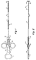
- FIG. 1 is a fragmented, partly broken away illustration of an endoscopic biopsy device in accordance with the present invention;
- FIG. 2 is a side view of the device as shown in FIG. 1 with the biopsy jaws in an open configuration;
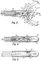
- FIG. 3 is an enlarged sectional illustration of the distal end of the device showing the biopsy jaws in an open configuration;
- FIG. 4 is an illustration similar to FIG. 3 with the biopsy jaws in a closed configuration;
- FIG. 5 is an illustration of the distal end of the device as seen along the line 5-5 of FIG. 4;
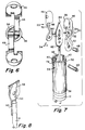
- FIG. 6 is an end view of the device as shown in FIG. 3 with the jaws open as seen from the right of FIG. 3;
- FIG. 7 is an exploded illustration of the components at the distal end of the device; and
- FIG. 8 is a further enlarged illustration of the connection between the
control wire 14 and the jaw and barb assembly. - As shown in FIGS. 1 and 2, the invention is embodied in a biopsy device having an elongate flexible
tubular shaft 10 which may be formed from a stainless steelhelical coil 12. Acontrol wire 12, that also may be formed from stainless steel, extends through the lumen 16 (see FIG. 3) defined by thehelical coil 12. Thecontrol wire 14 is connected to an actuating means 18 at the proximal end of the device by which the physician controls its operation. A pair ofbiopsy jaws 20 is carried at the distal end of theshaft 10. Thejaws 20 are operably associated with thecontrol wire 14 so that they may be closed (FIGS. 4, 5) or opened (FIGS. 2, 3) by operation of thecontrol wire 14. When thejaws 20 are closed, they define a diameter substantially the same as the outer diameter of theshaft 10 so that the entire device will fit slidably through the channel of the endoscope. For ease in description, directions or locations toward the longitudinal axis of the device will be referred to as "inward" while directions away from the longitudinal axis will be referred to as outward. Thus, the biopsy jaws may be considered to swing inwardly when they close and outwardly when they open. - The dimensions of the channel in the endoscope will vary for different types of endoscopes. For example, endoscopes used in gastrointestinal environments typically have a biopsy channel 2.8 mm in diameter whereas endoscopes for pulmonary use typically have a biopsy channel 2.0 mm in diameter. Additionally, the lengths of such endoscopes varies according to their use. Pulmonary endoscopes are shorter than gastrointestinal endoscopes. By way of further example, the
shaft 10 of the present invention may be of the order of between .070" to .080" in diameter and may be between 100 cm to 240 cm in length, depending on the type and size of the endoscope with which it is to be used. Other lengths and diameters may be appropriate for other types of endoscopes which may have different lengths and channel sizes. It may be desirable, in use, to coat the outer surface of thecoil 12 with a lubricious material. - The diameter of the
control wire 14 depends on the length of the device and, possibly, on the type of tissue which the device will be used to sample. The stiffness of the control wire is a function of its diameter. Preferably, the control wire usable for the particular type of endoscope should be the smallest diameter that will operate thejaws 20 so as not to adversely affect the flexibility of the device. By way of example, we have found that a control wire as small as .016" diameter may be effective to operate the jaws in a device 100 cm to 240 cm long. The control wire preferably is coated with Teflon (polytetrafluoroethylene) to enhance its ability to slide in thecoil 12. - As shown in FIGS. 1 and 2, the actuating means 18 includes a
stationary member 22 that is attached to the proximal end of thecoil 12. Thestationary member 22 preferably is provided with athumb socket 24. Thestationary member 22 also is provided, with a longitudinally extendingslot 26 that separates and defines a pair ofparallel rails 28. Amovable slide 30 is provided with a pair of finger holes and is slidably mounted to therails 28. The proximal end of thecoil 12 extends through anopening 32 in thestationary member 22 and guides thecontrol wire 14 to a point of attachment 31 on theslide 30. From the foregoing, it will be appreciated that the proximal end of the device can be operated with one hand, to pull proximally on thecontrol wire 14 or to push it distally. The device is arranged so that pushing on the wire opens thejaws 20 and pulling on thewire 14 causes thejaws 20 to close. - As shown in FIGS. 3-7, the device includes a jaw and barb assembly, indicated generally at 34 (FIGS. 3 and 7), and an asymmetrical tubular clevis indicated generally at 36. The
clevis 36 has aproximal end 38 that is securely attached to the distal end of thecoil 12 and a distal end having a pair ofslots - The jaw and
barb assembly 34 includes thebiopsy jaws 20 which, in turn, havearms 44, cutting cups 46 at the outer ends of thearms 44 and are pivoted to each other their inner ends at apivot pin 48. Each of the arms may be considered as having aproximal segment 50, an outwardly offsetintermediate segment 52 and adistal segment 54, the cuttingcup 46 for that jaw being integrally formed with the distal segment. The jaws may be machined or may be formed by other techniques such as metal injection molding. Thearms 44 and cups 46 are formed from stainless steel. The rim of eachcup 46 defines a sharpenededge 56. Thepivot pin 48 connects the arms at theirproximal segments 50. Theintermediate segment 52 is offset so that thedistal segment 54 and its associated cuttingcup 56 will be disposed outwardly of theproximal segment 50. - The device also may include a
barb 58 that extends longitudinally of the device. Thebarb 58 may be formed from a flat sheet of stainless steel interposed between the flat inwardly facingsurfaces 60 of theproximal segments 50 of thearms 44. Thebarb 58 has aproximal end 62 through which thepivot pin 48 is passed and adistal end 64 which is sharpened to a point. Theproximal end 62 of the barb is secured, as by anintegral extension 66 to the distal end of thecontrol wire 14. Theintermediate segment 52 of each of the arms also may be considered as having an inwardly facingcamming surface 68 and an outwardly facingcamming surface 70 which function in the manner described below. - The distal portion of the asymmetrical
tubular clevis 36 is arranged to receive the proximal andintermediate segments tubular clevis 36 includes the pair of asymmetrically arrangedslots slots arms 44, the width of each slot being just sufficient to receive the corresponding width of one of thearms 44. Engagement of the sides of thearms 44 with the facing sides of theslots arms 44 and guides them closely in inward and outward movement with minimal side-by-side movement. This further assures effective cooperative cutting by the inwardly facingsharp edges 56 of the cutting cups 46 when the cups are brought together. - Each of the
slots bottom surface 78. The tubular clevis also includes a camming member in the form of apin 80 attached at its ends to thedistal-most end walls 82 of thetubular clevis 36. Thepin 80 passes through a longitudinally extending slot 84 in thebarb 58 and serves to stabilize the barb in a longitudinally extending position. The slot 84 is sufficiently long to permit thebarb 58 to move lengthwise of theshaft 10 together with thejaws 20 as thecontrol wire 14 is operated. Thepin 80 is disposed with respect to the inner cam surfaces 68 of thearms 44 so that when thecontrol wire 14 is advanced distally, thedistally advancing arms 48 will be urged outwardly as the inner cam surfaces 68 advance against thepin 80. In order to close the jaws, thecontrol wire 14 is retracted proximally. In that motion, the outer cam surfaces 70 bear and slide against the bottom surfaces 78 of theslots arms 44 inwardly. The foregoing arrangement results in closure of the cups with relatively little longitudinal motion thereby enhancing a clean cut with minimal tearing of tissue. Thus, the jaws are caused to open by distal movement of the control wire and cooperation of thepin 80 with the inner cam surfaces while closure of the device is effected by proximal retraction of the control wire and resulting cooperation of the outer cam surfaces with the bottom surfaces 78 of the clevis. - The sharp tip of the
barb 58 serves to permit the device, with open jaws, to be brought firmly against the surface of tissue to be biopsied and by embedment in the tissue to maintain a fixed position of the jaws with respect to the tissue, even if the tissue is in motion, as is often the case when sampling tissue from a living patient. The jaws then simply may be closed by pulling on thecontrol wire 14, the barb retracting simultaneously with the closure motion. - From the foregoing, it will be appreciated that the invention provides an improved biopsy device having a simplified mechanism and including only a single pivot point. The device lends itself to relatively low cost manufacture and, therefore, is adaptable to disposable use. It should be understood, however, that the foregoing description of the invention is intended merely to be illustrative thereof and that other modifications, embodiments and equivalents may be apparent to those skilled in the art without departing from its spirit.
- Having thus described the invention what we desire to claim and secure by Letters Patent is:
Claims (8)
- A biopsy device comprising:
an elongate flexible tube having a proximal end and a distal end;
a pair of biopsy jaws each having a proximal end and an inner end, the inner ends of the biopsy jaws being pivoted to each other for closing inward and opening outward movement;
an actuating member extending through the tube and being connected at its distal end to the pivot, the actuating member being controllable from the proximal end of the device to be movable proximally or distally within the tube;
the jaws having inner and outer camming surfaces;
the distal end of the tube having surfaces engageable with the inner and outer camming surfaces of the jaws to cause the jaws to open when the actuating member is moved in one direction and to close when the actuating member is moved in the opposite direction. - A biopsy device as defined in claim 1 wherein each of the jaws further comprises:
an arm having an inner segment, an outwardly offset intermediate segment extending from the distal end of the inner segment and a distal segment extending from the distal end of the intermediate segment;
a biopsy cup attached to the distal segment of each arm. - A biopsy device as defined in claim 2 wherein the inner and outer camming surfaces are formed on the inner and outwardly facing surfaces of the intermediate segment.
- A biopsy device as defined in claim 2 further comprising:
the distal most end of the tube being formed to define a pair of slots, each slot being associated with and adapted to receive a portion of one of the arms, the width of each slot corresponding substantially to the width of the arm associated with the slot thereby to enable the arm to move through the slot while providing lateral stability for the arm. - A biopsy device as defined in claim 4 wherein the camming surfaces at the distal end of the tube comprise the bottom of the slots that receive the arms, said slot bottoms being engageable with the outer camming surfaces; and
a transverse member mounted to the distal end of the tube generally parallel to the pivot axis, the transverse member being engageable simultaneous with the inwardly facing camming surfaces. - A biopsy device as defined in claim 2 wherein the proximal segments of the arms are received substantially fully within the distal end of the tube when the jaws are closed thereby locking the jaws in a closed configuration.
- A biopsy device as defined in any one of claims 1-6 further comprising:
a barb member comprising a flat elongate plate having a proximal end captured between the jaws and pivoted to the pivot pin, the barb plate having a distally extending sharpened end and a stabilizer for maintaining the barb in a longitudinally oriented attitude. - A biopsy device as defined in claim 7 wherein the stabilizer comprises an elongate slot formed in the plate, the slot receiving the transverse member in a lost motion connection.
Applications Claiming Priority (2)
| Application Number | Priority Date | Filing Date | Title |
|---|---|---|---|
| US895321 | 1992-06-08 | ||
| US07/895,321 US5238002A (en) | 1992-06-08 | 1992-06-08 | Disposable biopsy forceps |
Publications (2)
| Publication Number | Publication Date |
|---|---|
| EP0573817A1 true EP0573817A1 (en) | 1993-12-15 |
| EP0573817B1 EP0573817B1 (en) | 1998-07-15 |
Family
ID=25404332
Family Applications (1)
| Application Number | Title | Priority Date | Filing Date |
|---|---|---|---|
| EP93108009A Expired - Lifetime EP0573817B1 (en) | 1992-06-08 | 1993-05-17 | Disposable biopsy forceps |
Country Status (6)
| Country | Link |
|---|---|
| US (1) | US5238002A (en) |
| EP (1) | EP0573817B1 (en) |
| JP (1) | JPH0630942A (en) |
| CA (1) | CA2097883A1 (en) |
| DE (1) | DE69319668T2 (en) |
| ES (1) | ES2118164T3 (en) |
Cited By (12)
| Publication number | Priority date | Publication date | Assignee | Title |
|---|---|---|---|---|
| EP0712608A3 (en) * | 1994-11-11 | 1996-06-12 | Olympus Optical Co | |
| WO1996029936A1 (en) * | 1995-03-28 | 1996-10-03 | Symbiosis Corporation | Endoscopic multiple sample bioptome with enhanced biting action |
| EP0888746A2 (en) * | 1997-07-02 | 1999-01-07 | Aesculap AG & Co. KG | Surgical instrument having a tubular shaft |
| FR2767051A1 (en) * | 1997-08-07 | 1999-02-12 | Jean Marie Hugueny | IMPROVED PINCHING DEVICE, ESPECIALLY OF THE BIOPSY FORCEPS |
| EP0945105A1 (en) * | 1998-03-26 | 1999-09-29 | Nivarox-FAR S.A. | Rack guide for a sampling device, e.g. a biopsy forceps |
| US6010523A (en) * | 1996-07-18 | 2000-01-04 | Pierre Jean-Claude Sabin | Forceps instrument, especially of the biopsy forceps type |
| US6139563A (en) * | 1997-09-25 | 2000-10-31 | Allegiance Corporation | Surgical device with malleable shaft |
| US6155988A (en) * | 1998-03-26 | 2000-12-05 | Nivarox-Far S.A. | Device for taking samples, for example for a biopsy, and rack system fitted to such a device |
| EP0971633B1 (en) * | 1996-11-25 | 2007-01-03 | Symbiosis Corporation | Biopsy forceps instrument having irrigation and aspiration capabilities |
| DE102009018291A1 (en) | 2009-04-21 | 2010-10-28 | Erbe Elektromedizin Gmbh | Cryosurgical instrument |
| US8469993B2 (en) | 2003-06-18 | 2013-06-25 | Boston Scientific Scimed, Inc. | Endoscopic instruments |
| US9681857B2 (en) | 2003-06-18 | 2017-06-20 | Boston Scientific Scimed, Inc. | Endoscopic instruments and methods of manufacture |
Families Citing this family (89)
| Publication number | Priority date | Publication date | Assignee | Title |
|---|---|---|---|---|
| US5542432A (en) * | 1992-02-18 | 1996-08-06 | Symbiosis Corporation | Endoscopic multiple sample bioptome |
| US5419339A (en) * | 1992-04-09 | 1995-05-30 | Symbiosis Corporation | Flexible microsurgical instrument having ground distal coil portion |
| US5389072A (en) * | 1992-06-05 | 1995-02-14 | Mircor Biomedical, Inc. | Mechanism for manipulating a tool and flexible elongate device using the same |
| US6716232B1 (en) * | 1993-04-30 | 2004-04-06 | United States Surgical Corporation | Surgical instrument having an articulated jaw structure and a detachable knife |
| GB9309142D0 (en) * | 1993-05-04 | 1993-06-16 | Gyrus Medical Ltd | Laparoscopic instrument |
| JPH09503404A (en) * | 1993-09-20 | 1997-04-08 | ボストン・サイエンティフィック・コーポレーション | Multiple biopsy sample collection device |
| US5601585A (en) * | 1994-02-08 | 1997-02-11 | Boston Scientific Corporation | Multi-motion side-cutting biopsy sampling device |
| US5573008A (en) * | 1993-10-29 | 1996-11-12 | Boston Scientific Corporation | Multiple biopsy sampling coring device |
| US5599298A (en) * | 1993-12-30 | 1997-02-04 | Boston Scientific Corporation | Bodily sample collection balloon catheter method |
| US5409012A (en) * | 1993-12-30 | 1995-04-25 | Boston Scientific Corporation | Sample collection using catheter with expandable member |
| US5471992A (en) * | 1994-02-08 | 1995-12-05 | Boston Scientific Corporation | Multi-motion cutter multiple biopsy sampling device |
| US5871453A (en) * | 1994-02-08 | 1999-02-16 | Boston Scientific Corporation | Moveable sample tube multiple biopsy sampling device |
| DE4404766A1 (en) * | 1994-02-16 | 1995-08-17 | Georg Pauldrach | Foreign body and tissue samples removing forceps |
| US5535754A (en) * | 1994-03-04 | 1996-07-16 | Doherty; Thomas E. | Endoscopic biopsy forceps - disposable |
| US5490861A (en) * | 1994-07-14 | 1996-02-13 | Symbiosis Corporation | Track guided end effector assembly for use with endoscopic instruments |
| US5716374A (en) * | 1995-10-10 | 1998-02-10 | Symbiosis Corporation | Stamped clevis for endoscopic instruments and method of making the same |
| US5967973A (en) | 1996-04-26 | 1999-10-19 | United States Surgical | Surgical retractor and method of surgery |
| US5820630A (en) * | 1996-10-22 | 1998-10-13 | Annex Medical, Inc. | Medical forceps jaw assembly |
| US5895361A (en) * | 1997-02-14 | 1999-04-20 | Symbiosis Corporation | Esophageal biopsy jaw assembly and endoscopic instrument incorporating the same |
| US5904702A (en) * | 1997-08-14 | 1999-05-18 | University Of Massachusetts | Instrument for thoracic surgical procedures |
| US5976161A (en) * | 1998-01-07 | 1999-11-02 | University Of New Mexico | Tissue everting apparatus and method |
| US6200263B1 (en) | 1998-01-23 | 2001-03-13 | United States Surgical Corporation | Surgical instrument holder |
| WO1999037213A1 (en) | 1998-01-23 | 1999-07-29 | United States Surgical Corporation | Surgical instrument |
| US20020087148A1 (en) | 1998-02-24 | 2002-07-04 | Brock David L. | Flexible instrument |
| US6810281B2 (en) | 2000-12-21 | 2004-10-26 | Endovia Medical, Inc. | Medical mapping system |
| US7090683B2 (en) | 1998-02-24 | 2006-08-15 | Hansen Medical, Inc. | Flexible instrument |
| US7713190B2 (en) | 1998-02-24 | 2010-05-11 | Hansen Medical, Inc. | Flexible instrument |
| US6949106B2 (en) | 1998-02-24 | 2005-09-27 | Endovia Medical, Inc. | Surgical instrument |
| US8414598B2 (en) | 1998-02-24 | 2013-04-09 | Hansen Medical, Inc. | Flexible instrument |
| US7775972B2 (en) | 1998-02-24 | 2010-08-17 | Hansen Medical, Inc. | Flexible instrument |
| US6086606A (en) * | 1998-05-06 | 2000-07-11 | Knodel; Bryan D. | Manually-operable surgical tool suitable for laparoscopic operations, readily adaptable for different functions by quick change of tissue-contacting operational elements |
| US5980511A (en) * | 1998-05-15 | 1999-11-09 | T. Esser | Medical instrument handle with integral palm blocking member |
| US6106543A (en) * | 1998-05-15 | 2000-08-22 | Esser; Theodor | Medical instrument driving member and end effector connection |
| AUPP446998A0 (en) * | 1998-07-03 | 1998-07-30 | Baska, Kanag | Biopsy forceps |
| US6074408A (en) * | 1998-10-13 | 2000-06-13 | Freeman; Kenneth V. | Modular medical instrument and method of using same |
| US7416554B2 (en) | 2002-12-11 | 2008-08-26 | Usgi Medical Inc | Apparatus and methods for forming and securing gastrointestinal tissue folds |
| US7637905B2 (en) | 2003-01-15 | 2009-12-29 | Usgi Medical, Inc. | Endoluminal tool deployment system |
| US6309404B1 (en) | 1999-10-19 | 2001-10-30 | Jacek Krzyzanowski | Flexible biopsy jaw assembly |
| ITCE990004A1 (en) * | 1999-10-25 | 2000-01-25 | Mario Immacolato Paternuosto | VALVE FOR BIOPSY FORCEPS IN DIGESTIVE ENDOSCOPY |
| US6419640B1 (en) * | 2000-10-03 | 2002-07-16 | Thomas V. Taylor | Multiple-specimen, endoscopic biopsy forceps |
| US8414505B1 (en) | 2001-02-15 | 2013-04-09 | Hansen Medical, Inc. | Catheter driver system |
| US7699835B2 (en) | 2001-02-15 | 2010-04-20 | Hansen Medical, Inc. | Robotically controlled surgical instruments |
| US7766894B2 (en) | 2001-02-15 | 2010-08-03 | Hansen Medical, Inc. | Coaxial catheter system |
| US20030135204A1 (en) * | 2001-02-15 | 2003-07-17 | Endo Via Medical, Inc. | Robotically controlled medical instrument with a flexible section |
| US6440085B1 (en) * | 2001-06-12 | 2002-08-27 | Jacek Krzyzanowski | Method of assembling a non-metallic biopsy forceps jaw and a non-metallic biopsy forceps jaw |
| US7137949B2 (en) | 2001-07-13 | 2006-11-21 | United States Surgical Corporation | Surgical instrument |
| DE10156313A1 (en) * | 2001-11-19 | 2003-06-05 | Wolf Gmbh Richard | Medical forceps |
| WO2003086201A1 (en) | 2002-04-05 | 2003-10-23 | Allegiance Corporation | Improved biopsy needle and biopsy device containing the same |
| US20040176751A1 (en) * | 2002-08-14 | 2004-09-09 | Endovia Medical, Inc. | Robotic medical instrument system |
| US7837631B2 (en) * | 2003-03-14 | 2010-11-23 | Boston Scientific Scimed Inc. | Biopsy forceps with removable jaw segments |
| US7025775B2 (en) * | 2003-05-15 | 2006-04-11 | Applied Medical Resources Corporation | Surgical instrument with removable shaft apparatus and method |
| US7775989B2 (en) * | 2003-09-03 | 2010-08-17 | Granit Medical Innovations, Llc | Needle biopsy forceps with integral sample ejector |
| EP2455016B1 (en) * | 2003-09-09 | 2014-06-18 | Olympus Corporation | Treatment tool for endoscope |
| US7588545B2 (en) | 2003-09-10 | 2009-09-15 | Boston Scientific Scimed, Inc. | Forceps and collection assembly with accompanying mechanisms and related methods of use |
| US7942896B2 (en) | 2003-11-25 | 2011-05-17 | Scimed Life Systems, Inc. | Forceps and collection assembly and related methods of use and manufacture |
| US20050137585A1 (en) * | 2003-12-23 | 2005-06-23 | Jamie Landman | Back loading endoscopic instruments |
| EP1838229B1 (en) * | 2005-01-20 | 2009-08-26 | Wilson-Cook Medical Inc. | Biopsy forceps |
| US20060178656A1 (en) * | 2005-02-09 | 2006-08-10 | Pentax Corporation | Treatment tool for endoscope |
| WO2006096169A1 (en) * | 2005-03-03 | 2006-09-14 | Granit Medical Innovations, Llc | Needle biopsy forceps with integral sample ejector |
| US7762960B2 (en) * | 2005-05-13 | 2010-07-27 | Boston Scientific Scimed, Inc. | Biopsy forceps assemblies |
| US7857827B2 (en) | 2006-04-14 | 2010-12-28 | Ethicon Endo-Surgery, Inc. | Endoscopic device |
| US20070244513A1 (en) * | 2006-04-14 | 2007-10-18 | Ethicon Endo-Surgery, Inc. | Endoscopic device |
| US8740853B2 (en) | 2006-04-14 | 2014-06-03 | Ethicon Endo-Surgery, Inc. | Endoscopic device and method of packaging |
| US7998167B2 (en) | 2006-04-14 | 2011-08-16 | Ethicon Endo-Surgery, Inc. | End effector and method of manufacture |
| US8414616B2 (en) * | 2006-09-12 | 2013-04-09 | Pioneer Surgical Technology, Inc. | Mounting devices for fixation devices and insertion instruments used therewith |
| WO2008067281A1 (en) * | 2006-11-30 | 2008-06-05 | Vance Products Incorporated D/B/A Cook Urological Incorporated | Removable handle for medical device |
| US9005238B2 (en) * | 2007-08-23 | 2015-04-14 | Covidien Lp | Endoscopic surgical devices |
| US20090259141A1 (en) * | 2008-03-21 | 2009-10-15 | Usgi Medical, Inc. | Steerable tool guide for use with flexible endoscopic medical devices |
| US8579921B2 (en) * | 2008-06-18 | 2013-11-12 | Covidien Lp | Spring-type suture securing device |
| US8636761B2 (en) * | 2008-10-09 | 2014-01-28 | Covidien Lp | Apparatus, system, and method for performing an endoscopic electrosurgical procedure |
| US8465476B2 (en) | 2009-09-23 | 2013-06-18 | Intuitive Surgical Operations, Inc. | Cannula mounting fixture |
| US20110071541A1 (en) * | 2009-09-23 | 2011-03-24 | Intuitive Surgical, Inc. | Curved cannula |
| US8623028B2 (en) | 2009-09-23 | 2014-01-07 | Intuitive Surgical Operations, Inc. | Surgical port feature |
| US8888789B2 (en) | 2009-09-23 | 2014-11-18 | Intuitive Surgical Operations, Inc. | Curved cannula surgical system control |
| US9737320B2 (en) | 2010-03-18 | 2017-08-22 | Covidien Lp | Surgical grasper with integrated probe |
| US8585736B2 (en) | 2010-06-02 | 2013-11-19 | Covidien Lp | Apparatus for performing an electrosurgical procedure |
| WO2012149468A2 (en) * | 2011-04-29 | 2012-11-01 | University Of Southern California | Instruments and methods for the implantation of cell-seeded substrates |
| US10624664B2 (en) * | 2011-09-28 | 2020-04-21 | Evalve, Inc. | Apparatuses and methods for cutting a tissue bridge and/or removing a heart valve clip or suture |
| US9265514B2 (en) | 2012-04-17 | 2016-02-23 | Miteas Ltd. | Manipulator for grasping tissue |
| US9693790B2 (en) * | 2012-08-02 | 2017-07-04 | Covidien Lp | Laparoscopic gallbladder extraction device |
| US9357984B2 (en) | 2013-04-23 | 2016-06-07 | Covidien Lp | Constant value gap stabilizer for articulating links |
| US9468453B2 (en) | 2013-05-03 | 2016-10-18 | Covidien Lp | Endoscopic surgical forceps |
| KR20190117629A (en) * | 2017-02-22 | 2019-10-16 | 야첵 크지자노프스키 | Jaw assembly and biopsy sample collection member for surgical instruments |
| US20190254644A1 (en) * | 2018-02-22 | 2019-08-22 | Boston Scientific Limited | Biopsy forceps with cam mechanism |
| CN109498149B (en) * | 2018-12-27 | 2024-03-29 | 北京术锐机器人股份有限公司 | Surgical tool |
| CN113905673A (en) | 2019-05-20 | 2022-01-07 | 波士顿科学有限公司 | Endoscopic medical device |
| US11737844B2 (en) * | 2020-08-19 | 2023-08-29 | Covidien Lp | End effector assembly for use in a robotic surgical instrument |
| EP3967243B1 (en) * | 2020-09-15 | 2024-01-17 | Beijing Longmiao Medical Device Co., Ltd. | Biopsy forceps and jaw assembly thereof |
| CN114947995A (en) * | 2021-02-22 | 2022-08-30 | 常州朗合医疗器械有限公司 | Biopsy forceps |
Citations (5)
| Publication number | Priority date | Publication date | Assignee | Title |
|---|---|---|---|---|
| EP0207829A1 (en) * | 1985-06-04 | 1987-01-07 | Jean-Marie Schintgen | Biopsy forceps with a retractable needle |
| EP0317526A1 (en) * | 1987-11-16 | 1989-05-24 | Consiglio Nazionale Delle Ricerche | A catheter for endocardial biopsy, which can also be used for identifying the point of origin of ventricular arrythmia |
| WO1989010093A1 (en) * | 1988-04-27 | 1989-11-02 | Esco Precision, Inc. | Endoscopic biopsy forceps device |
| WO1990001297A1 (en) * | 1988-08-11 | 1990-02-22 | Crillon Jean Louis | Gripping device and method, for example for biopsy |
| EP0380874A1 (en) * | 1989-01-31 | 1990-08-08 | C.R. Bard, Inc. | Disposable biopsy forceps |
Family Cites Families (11)
| Publication number | Priority date | Publication date | Assignee | Title |
|---|---|---|---|---|
| US430849A (en) * | 1890-06-24 | Frederick w | ||
| US391532A (en) * | 1888-10-23 | Wrench | ||
| US2060366A (en) * | 1935-10-18 | 1936-11-10 | Carson Ray Lilly | Animal catcher |
| US3895636A (en) * | 1973-09-24 | 1975-07-22 | William Schmidt | Flexible forceps |
| US5133727A (en) * | 1990-05-10 | 1992-07-28 | Symbiosis Corporation | Radial jaw biopsy forceps |
| US4200111A (en) * | 1978-09-21 | 1980-04-29 | Harris Arthur M | Specimen removal instrument |
| FR2505170B1 (en) * | 1981-05-06 | 1985-08-02 | Metallisations Traitements Opt | BIOPSY TONGS |
| US4721116A (en) * | 1985-06-04 | 1988-01-26 | Schintgen Jean Marie | Retractable needle biopsy forceps and improved control cable therefor |
| DE8702446U1 (en) * | 1987-02-18 | 1987-10-08 | Kothe, Lutz, 7760 Radolfzell, De | |
| US5052402A (en) * | 1989-01-31 | 1991-10-01 | C.R. Bard, Inc. | Disposable biopsy forceps |
| US5082000A (en) * | 1990-11-29 | 1992-01-21 | Applied Medical Technology, Inc. | Biopsy forceps with calde controlled jaws |
-
1992
- 1992-06-08 US US07/895,321 patent/US5238002A/en not_active Expired - Lifetime
-
1993
- 1993-05-17 EP EP93108009A patent/EP0573817B1/en not_active Expired - Lifetime
- 1993-05-17 ES ES93108009T patent/ES2118164T3/en not_active Expired - Lifetime
- 1993-05-17 DE DE69319668T patent/DE69319668T2/en not_active Expired - Lifetime
- 1993-06-02 JP JP5132034A patent/JPH0630942A/en active Pending
- 1993-06-07 CA CA002097883A patent/CA2097883A1/en not_active Abandoned
Patent Citations (5)
| Publication number | Priority date | Publication date | Assignee | Title |
|---|---|---|---|---|
| EP0207829A1 (en) * | 1985-06-04 | 1987-01-07 | Jean-Marie Schintgen | Biopsy forceps with a retractable needle |
| EP0317526A1 (en) * | 1987-11-16 | 1989-05-24 | Consiglio Nazionale Delle Ricerche | A catheter for endocardial biopsy, which can also be used for identifying the point of origin of ventricular arrythmia |
| WO1989010093A1 (en) * | 1988-04-27 | 1989-11-02 | Esco Precision, Inc. | Endoscopic biopsy forceps device |
| WO1990001297A1 (en) * | 1988-08-11 | 1990-02-22 | Crillon Jean Louis | Gripping device and method, for example for biopsy |
| EP0380874A1 (en) * | 1989-01-31 | 1990-08-08 | C.R. Bard, Inc. | Disposable biopsy forceps |
Cited By (21)
| Publication number | Priority date | Publication date | Assignee | Title |
|---|---|---|---|---|
| EP0712608A3 (en) * | 1994-11-11 | 1996-06-12 | Olympus Optical Co | |
| WO1996029936A1 (en) * | 1995-03-28 | 1996-10-03 | Symbiosis Corporation | Endoscopic multiple sample bioptome with enhanced biting action |
| AU696599B2 (en) * | 1995-03-28 | 1998-09-17 | Symbiosis Corporation | Endoscopic multiple sample bioptome with enhanced biting action |
| US6010523A (en) * | 1996-07-18 | 2000-01-04 | Pierre Jean-Claude Sabin | Forceps instrument, especially of the biopsy forceps type |
| EP0971633B1 (en) * | 1996-11-25 | 2007-01-03 | Symbiosis Corporation | Biopsy forceps instrument having irrigation and aspiration capabilities |
| EP0888746A2 (en) * | 1997-07-02 | 1999-01-07 | Aesculap AG & Co. KG | Surgical instrument having a tubular shaft |
| EP0888746A3 (en) * | 1997-07-02 | 2001-01-24 | Aesculap AG & Co. KG | Surgical instrument having a tubular shaft |
| WO1999007287A1 (en) * | 1997-08-07 | 1999-02-18 | Sabin Jean Louis | Improved forceps, in particular biopsy forceps |
| US6425910B1 (en) | 1997-08-07 | 2002-07-30 | Eurobiopsy | Forceps, in particular biopsy forceps |
| FR2767051A1 (en) * | 1997-08-07 | 1999-02-12 | Jean Marie Hugueny | IMPROVED PINCHING DEVICE, ESPECIALLY OF THE BIOPSY FORCEPS |
| US6139563A (en) * | 1997-09-25 | 2000-10-31 | Allegiance Corporation | Surgical device with malleable shaft |
| US6155988A (en) * | 1998-03-26 | 2000-12-05 | Nivarox-Far S.A. | Device for taking samples, for example for a biopsy, and rack system fitted to such a device |
| EP0945105A1 (en) * | 1998-03-26 | 1999-09-29 | Nivarox-FAR S.A. | Rack guide for a sampling device, e.g. a biopsy forceps |
| US8469993B2 (en) | 2003-06-18 | 2013-06-25 | Boston Scientific Scimed, Inc. | Endoscopic instruments |
| US9681857B2 (en) | 2003-06-18 | 2017-06-20 | Boston Scientific Scimed, Inc. | Endoscopic instruments and methods of manufacture |
| WO2010121739A1 (en) | 2009-04-21 | 2010-10-28 | Erbe Elektromedizin Gmbh | Cryosurgical instrument |
| WO2010121738A1 (en) | 2009-04-21 | 2010-10-28 | Erbe Elektromedizin Gmbh | Cryosurgical instrument |
| CN102481166A (en) * | 2009-04-21 | 2012-05-30 | 厄比电子医学有限责任公司 | Cryosurgical instrument |
| DE102009018291A1 (en) | 2009-04-21 | 2010-10-28 | Erbe Elektromedizin Gmbh | Cryosurgical instrument |
| CN102481166B (en) * | 2009-04-21 | 2015-01-28 | 厄比电子医学有限责任公司 | Cryosurgical instrument |
| US11229476B2 (en) | 2009-04-21 | 2022-01-25 | Erbe Elektromedizin Gmbh | Cryosurgical instrument |
Also Published As
| Publication number | Publication date |
|---|---|
| ES2118164T3 (en) | 1998-09-16 |
| EP0573817B1 (en) | 1998-07-15 |
| DE69319668D1 (en) | 1998-08-20 |
| CA2097883A1 (en) | 1993-12-09 |
| JPH0630942A (en) | 1994-02-08 |
| US5238002A (en) | 1993-08-24 |
| DE69319668T2 (en) | 1998-12-24 |
Similar Documents
| Publication | Publication Date | Title |
|---|---|---|
| US5238002A (en) | Disposable biopsy forceps | |
| US6561988B1 (en) | Endoscopic multiple sample bioptome with enhanced biting action | |
| US5172700A (en) | Disposable biopsy forceps | |
| EP1221896B1 (en) | Biopsy jaw assembly | |
| US5052402A (en) | Disposable biopsy forceps | |
| US5779648A (en) | Multi-motion cutter multiple biopsy sampling device | |
| US5797957A (en) | Endoscopic bioptome with a hard stop to control biting force | |
| US6083150A (en) | Endoscopic multiple sample biopsy forceps | |
| EP0380874A1 (en) | Disposable biopsy forceps | |
| US5458112A (en) | Biliary biopsy device | |
| US6053877A (en) | Movable sample tube multiple biopsy sampling device | |
| US6273860B1 (en) | Biopsy apparatus | |
| JP3691060B2 (en) | Multi-action specimen collection device for multiple biopsies | |
| CN110381848B (en) | Clamp assembly and biopsy sample collection member for surgical tool | |
| WO2000007502A1 (en) | Articulated medical device | |
| JPH09503404A (en) | Multiple biopsy sample collection device | |
| US6461310B1 (en) | Endoscopic bioptome with a hard stop to control biting force | |
| US20120179064A1 (en) | Surgical instrument | |
| JPH03139340A (en) | Treating implement for endoscope | |
| CN114746026A (en) | Biopsy forceps with tissue piercing member | |
| JP2005021346A (en) | Forceps for endoscope | |
| CA2172128A1 (en) | Multiple biopsy sampling forceps | |
| IES930033A2 (en) | "Improved Forceps" |
Legal Events
| Date | Code | Title | Description |
|---|---|---|---|
| PUAI | Public reference made under article 153(3) epc to a published international application that has entered the european phase |
Free format text: ORIGINAL CODE: 0009012 |
|
| AK | Designated contracting states |
Kind code of ref document: A1 Designated state(s): DE ES FR GB |
|
| 17P | Request for examination filed |
Effective date: 19940607 |
|
| 17Q | First examination report despatched |
Effective date: 19950920 |
|
| GRAG | Despatch of communication of intention to grant |
Free format text: ORIGINAL CODE: EPIDOS AGRA |
|
| GRAG | Despatch of communication of intention to grant |
Free format text: ORIGINAL CODE: EPIDOS AGRA |
|
| GRAH | Despatch of communication of intention to grant a patent |
Free format text: ORIGINAL CODE: EPIDOS IGRA |
|
| GRAH | Despatch of communication of intention to grant a patent |
Free format text: ORIGINAL CODE: EPIDOS IGRA |
|
| GRAA | (expected) grant |
Free format text: ORIGINAL CODE: 0009210 |
|
| AK | Designated contracting states |
Kind code of ref document: B1 Designated state(s): DE ES FR GB |
|
| REF | Corresponds to: |
Ref document number: 69319668 Country of ref document: DE Date of ref document: 19980820 |
|
| REG | Reference to a national code |
Ref country code: ES Ref legal event code: FG2A Ref document number: 2118164 Country of ref document: ES Kind code of ref document: T3 |
|
| ET | Fr: translation filed | ||
| PLBE | No opposition filed within time limit |
Free format text: ORIGINAL CODE: 0009261 |
|
| STAA | Information on the status of an ep patent application or granted ep patent |
Free format text: STATUS: NO OPPOSITION FILED WITHIN TIME LIMIT |
|
| 26N | No opposition filed | ||
| REG | Reference to a national code |
Ref country code: GB Ref legal event code: IF02 |
|
| PGFP | Annual fee paid to national office [announced via postgrant information from national office to epo] |
Ref country code: ES Payment date: 20090518 Year of fee payment: 17 |
|
| PGFP | Annual fee paid to national office [announced via postgrant information from national office to epo] |
Ref country code: FR Payment date: 20090507 Year of fee payment: 17 |
|
| PGFP | Annual fee paid to national office [announced via postgrant information from national office to epo] |
Ref country code: DE Payment date: 20100531 Year of fee payment: 18 |
|
| PGFP | Annual fee paid to national office [announced via postgrant information from national office to epo] |
Ref country code: GB Payment date: 20100401 Year of fee payment: 18 |
|
| REG | Reference to a national code |
Ref country code: FR Ref legal event code: ST Effective date: 20110131 |
|
| PG25 | Lapsed in a contracting state [announced via postgrant information from national office to epo] |
Ref country code: FR Free format text: LAPSE BECAUSE OF NON-PAYMENT OF DUE FEES Effective date: 20100531 |
|
| REG | Reference to a national code |
Ref country code: ES Ref legal event code: FD2A Effective date: 20110715 |
|
| PG25 | Lapsed in a contracting state [announced via postgrant information from national office to epo] |
Ref country code: ES Free format text: LAPSE BECAUSE OF NON-PAYMENT OF DUE FEES Effective date: 20110705 |
|
| PG25 | Lapsed in a contracting state [announced via postgrant information from national office to epo] |
Ref country code: ES Free format text: LAPSE BECAUSE OF NON-PAYMENT OF DUE FEES Effective date: 20100518 |
|
| REG | Reference to a national code |
Ref country code: DE Ref legal event code: R119 Ref document number: 69319668 Country of ref document: DE |
|
| REG | Reference to a national code |
Ref country code: DE Ref legal event code: R119 Ref document number: 69319668 Country of ref document: DE |
|
| GBPC | Gb: european patent ceased through non-payment of renewal fee |
Effective date: 20110517 |
|
| PG25 | Lapsed in a contracting state [announced via postgrant information from national office to epo] |
Ref country code: GB Free format text: LAPSE BECAUSE OF NON-PAYMENT OF DUE FEES Effective date: 20110517 |
|
| PG25 | Lapsed in a contracting state [announced via postgrant information from national office to epo] |
Ref country code: DE Free format text: LAPSE BECAUSE OF NON-PAYMENT OF DUE FEES Effective date: 20111130 |