EP0575014A1 - Liquid dispenser nozzle - Google Patents
Liquid dispenser nozzle Download PDFInfo
- Publication number
- EP0575014A1 EP0575014A1 EP19930201800 EP93201800A EP0575014A1 EP 0575014 A1 EP0575014 A1 EP 0575014A1 EP 19930201800 EP19930201800 EP 19930201800 EP 93201800 A EP93201800 A EP 93201800A EP 0575014 A1 EP0575014 A1 EP 0575014A1
- Authority
- EP
- European Patent Office
- Prior art keywords
- liquid
- nozzle assembly
- valve
- diaphragm
- air
- Prior art date
- Legal status (The legal status is an assumption and is not a legal conclusion. Google has not performed a legal analysis and makes no representation as to the accuracy of the status listed.)
- Withdrawn
Links
Images


Classifications
-
- B—PERFORMING OPERATIONS; TRANSPORTING
- B05—SPRAYING OR ATOMISING IN GENERAL; APPLYING FLUENT MATERIALS TO SURFACES, IN GENERAL
- B05B—SPRAYING APPARATUS; ATOMISING APPARATUS; NOZZLES
- B05B11/00—Single-unit hand-held apparatus in which flow of contents is produced by the muscular force of the operator at the moment of use
- B05B11/0005—Components or details
- B05B11/0062—Outlet valves actuated by the pressure of the fluid to be sprayed
- B05B11/007—Outlet valves actuated by the pressure of the fluid to be sprayed being opened by deformation of a sealing element made of resiliently deformable material, e.g. flaps, skirts, duck-bill valves
-
- A—HUMAN NECESSITIES
- A61—MEDICAL OR VETERINARY SCIENCE; HYGIENE
- A61F—FILTERS IMPLANTABLE INTO BLOOD VESSELS; PROSTHESES; DEVICES PROVIDING PATENCY TO, OR PREVENTING COLLAPSING OF, TUBULAR STRUCTURES OF THE BODY, e.g. STENTS; ORTHOPAEDIC, NURSING OR CONTRACEPTIVE DEVICES; FOMENTATION; TREATMENT OR PROTECTION OF EYES OR EARS; BANDAGES, DRESSINGS OR ABSORBENT PADS; FIRST-AID KITS
- A61F9/00—Methods or devices for treatment of the eyes; Devices for putting-in contact lenses; Devices to correct squinting; Apparatus to guide the blind; Protective devices for the eyes, carried on the body or in the hand
- A61F9/0008—Introducing ophthalmic products into the ocular cavity or retaining products therein
-
- B—PERFORMING OPERATIONS; TRANSPORTING
- B05—SPRAYING OR ATOMISING IN GENERAL; APPLYING FLUENT MATERIALS TO SURFACES, IN GENERAL
- B05B—SPRAYING APPARATUS; ATOMISING APPARATUS; NOZZLES
- B05B11/00—Single-unit hand-held apparatus in which flow of contents is produced by the muscular force of the operator at the moment of use
- B05B11/0005—Components or details
- B05B11/0037—Containers
- B05B11/0039—Containers associated with means for compensating the pressure difference between the ambient pressure and the pressure inside the container, e.g. pressure relief means
- B05B11/0044—Containers associated with means for compensating the pressure difference between the ambient pressure and the pressure inside the container, e.g. pressure relief means compensating underpressure by ingress of atmospheric air into the container, i.e. with venting means
- B05B11/00444—Containers associated with means for compensating the pressure difference between the ambient pressure and the pressure inside the container, e.g. pressure relief means compensating underpressure by ingress of atmospheric air into the container, i.e. with venting means with provision for filtering or cleaning the air flow drawn into the container
-
- B—PERFORMING OPERATIONS; TRANSPORTING
- B05—SPRAYING OR ATOMISING IN GENERAL; APPLYING FLUENT MATERIALS TO SURFACES, IN GENERAL
- B05B—SPRAYING APPARATUS; ATOMISING APPARATUS; NOZZLES
- B05B11/00—Single-unit hand-held apparatus in which flow of contents is produced by the muscular force of the operator at the moment of use
- B05B11/01—Single-unit hand-held apparatus in which flow of contents is produced by the muscular force of the operator at the moment of use characterised by the means producing the flow
- B05B11/04—Deformable containers producing the flow, e.g. squeeze bottles
- B05B11/047—Deformable containers producing the flow, e.g. squeeze bottles characterised by the outlet or venting means
-
- B—PERFORMING OPERATIONS; TRANSPORTING
- B05—SPRAYING OR ATOMISING IN GENERAL; APPLYING FLUENT MATERIALS TO SURFACES, IN GENERAL
- B05B—SPRAYING APPARATUS; ATOMISING APPARATUS; NOZZLES
- B05B11/00—Single-unit hand-held apparatus in which flow of contents is produced by the muscular force of the operator at the moment of use
- B05B11/01—Single-unit hand-held apparatus in which flow of contents is produced by the muscular force of the operator at the moment of use characterised by the means producing the flow
- B05B11/04—Deformable containers producing the flow, e.g. squeeze bottles
- B05B11/048—Deformable containers producing the flow, e.g. squeeze bottles characterised by the container, e.g. this latter being surrounded by an enclosure, or the means for deforming it
-
- B—PERFORMING OPERATIONS; TRANSPORTING
- B65—CONVEYING; PACKING; STORING; HANDLING THIN OR FILAMENTARY MATERIAL
- B65D—CONTAINERS FOR STORAGE OR TRANSPORT OF ARTICLES OR MATERIALS, e.g. BAGS, BARRELS, BOTTLES, BOXES, CANS, CARTONS, CRATES, DRUMS, JARS, TANKS, HOPPERS, FORWARDING CONTAINERS; ACCESSORIES, CLOSURES, OR FITTINGS THEREFOR; PACKAGING ELEMENTS; PACKAGES
- B65D47/00—Closures with filling and discharging, or with discharging, devices
- B65D47/04—Closures with discharging devices other than pumps
- B65D47/06—Closures with discharging devices other than pumps with pouring spouts or tubes; with discharge nozzles or passages
- B65D47/12—Closures with discharging devices other than pumps with pouring spouts or tubes; with discharge nozzles or passages having removable closures
- B65D47/14—Closures with discharging devices other than pumps with pouring spouts or tubes; with discharge nozzles or passages having removable closures and closure-retaining means
- B65D47/147—Closures with discharging devices other than pumps with pouring spouts or tubes; with discharge nozzles or passages having removable closures and closure-retaining means for snap-on caps
-
- B—PERFORMING OPERATIONS; TRANSPORTING
- B65—CONVEYING; PACKING; STORING; HANDLING THIN OR FILAMENTARY MATERIAL
- B65D—CONTAINERS FOR STORAGE OR TRANSPORT OF ARTICLES OR MATERIALS, e.g. BAGS, BARRELS, BOTTLES, BOXES, CANS, CARTONS, CRATES, DRUMS, JARS, TANKS, HOPPERS, FORWARDING CONTAINERS; ACCESSORIES, CLOSURES, OR FITTINGS THEREFOR; PACKAGING ELEMENTS; PACKAGES
- B65D47/00—Closures with filling and discharging, or with discharging, devices
- B65D47/04—Closures with discharging devices other than pumps
- B65D47/20—Closures with discharging devices other than pumps comprising hand-operated members for controlling discharge
- B65D47/2018—Closures with discharging devices other than pumps comprising hand-operated members for controlling discharge comprising a valve or like element which is opened or closed by deformation of the container or closure
- B65D47/2056—Closures with discharging devices other than pumps comprising hand-operated members for controlling discharge comprising a valve or like element which is opened or closed by deformation of the container or closure lift valve type
- B65D47/2081—Closures with discharging devices other than pumps comprising hand-operated members for controlling discharge comprising a valve or like element which is opened or closed by deformation of the container or closure lift valve type in which the deformation raises or lowers the valve port
-
- B—PERFORMING OPERATIONS; TRANSPORTING
- B65—CONVEYING; PACKING; STORING; HANDLING THIN OR FILAMENTARY MATERIAL
- B65D—CONTAINERS FOR STORAGE OR TRANSPORT OF ARTICLES OR MATERIALS, e.g. BAGS, BARRELS, BOTTLES, BOXES, CANS, CARTONS, CRATES, DRUMS, JARS, TANKS, HOPPERS, FORWARDING CONTAINERS; ACCESSORIES, CLOSURES, OR FITTINGS THEREFOR; PACKAGING ELEMENTS; PACKAGES
- B65D83/00—Containers or packages with special means for dispensing contents
- B65D83/0055—Containers or packages provided with a flexible bag or a deformable membrane or diaphragm for expelling the contents
-
- A—HUMAN NECESSITIES
- A61—MEDICAL OR VETERINARY SCIENCE; HYGIENE
- A61J—CONTAINERS SPECIALLY ADAPTED FOR MEDICAL OR PHARMACEUTICAL PURPOSES; DEVICES OR METHODS SPECIALLY ADAPTED FOR BRINGING PHARMACEUTICAL PRODUCTS INTO PARTICULAR PHYSICAL OR ADMINISTERING FORMS; DEVICES FOR ADMINISTERING FOOD OR MEDICINES ORALLY; BABY COMFORTERS; DEVICES FOR RECEIVING SPITTLE
- A61J1/00—Containers specially adapted for medical or pharmaceutical purposes
- A61J1/14—Details; Accessories therefor
- A61J1/1443—Containers with means for dispensing liquid medicaments in a filtered or sterile way, e.g. with bacterial filters
- A61J1/145—Containers with means for dispensing liquid medicaments in a filtered or sterile way, e.g. with bacterial filters using air filters
-
- A—HUMAN NECESSITIES
- A61—MEDICAL OR VETERINARY SCIENCE; HYGIENE
- A61J—CONTAINERS SPECIALLY ADAPTED FOR MEDICAL OR PHARMACEUTICAL PURPOSES; DEVICES OR METHODS SPECIALLY ADAPTED FOR BRINGING PHARMACEUTICAL PRODUCTS INTO PARTICULAR PHYSICAL OR ADMINISTERING FORMS; DEVICES FOR ADMINISTERING FOOD OR MEDICINES ORALLY; BABY COMFORTERS; DEVICES FOR RECEIVING SPITTLE
- A61J1/00—Containers specially adapted for medical or pharmaceutical purposes
- A61J1/14—Details; Accessories therefor
- A61J1/1468—Containers characterised by specific material properties
-
- B—PERFORMING OPERATIONS; TRANSPORTING
- B01—PHYSICAL OR CHEMICAL PROCESSES OR APPARATUS IN GENERAL
- B01D—SEPARATION
- B01D2201/00—Details relating to filtering apparatus
- B01D2201/30—Filter housing constructions
- B01D2201/301—Details of removable closures, lids, caps, filter heads
- B01D2201/302—Details of removable closures, lids, caps, filter heads having inlet or outlet ports
Definitions
- the present invention relates to liquid storage containers for manually dispensing liquids such as cleaning solutions for contact lenses, and more particularly relates to dispensing nozzles on containers for liquid which must be stored in sterile condition.
- Liquids for example, solutions for cleaning and conditioning contact lenses
- squeezable bottles from which the user can repeatedly dispense the stored liquid.
- These liquids must be uncontaminated by microorganisms such as bacteria.
- expensive bacteriacidal agents have sometimes been included in the liquid formulation, as for example, in saline formations for cleaning contact lenses.
- the squeezable dispensing bottles have sometimes been provided with nozzles including filter membranes which are permeable to the dispensed liquid as well as being permeable to the air which must be aspirated through the nozzle to replace the dispensed liquid.
- filter membrances are also impermeable to bacteria in order to prevent the aspirated air from carrying bacteria into contact with the stored solution, so that the solution is maintained in sterile condition for repeated dispensing.
- filter membrane materials which are sufficiently hydrophilic to permit permeation of the saline solutions often permit retention of the saline on the filter so that the retained solution increases the resistance of the filter to passage of the aspirating air.
- the partially obstructed flow of aspirating air not only retards the expansion of the squeezed bottle wall, but also impedes a subsequent squeezing of the bottle when a demand for large quantities of the solution must be dispensed.
- the object of this invention is to provide a nozzle assembly that affords accelerated air aspiration of a squeezed liquid dispensing bottle for improved convenience to the user, particularly in repeated dispensing of solutions for contact lenses.
- a liquid dispensing nozzle assembly for mounting on a liquid container and dispenser having a flexible wall and liquid storage cavity for manually squeezed dispensing of liquid from the cavity through the nozzle assembly and for maintaining the liquid in sterile condition during storage and repeated dispensing of the liquid from the container cavity, the nozzle assembly comprising a liquid discharge port; liquid conduit means for communication from the container cavity to the liquid discharge port to enable dispensing of the liquid displaced by manually squeezing the flexible wall of the container, and is characterised in that the nozzle assembly further comprises: air aspiration conduit means separate from the liquid conduit for aspirating air into the container cavity to replace the liquid dispensed therefrom; and partitioned diaphragm means integrally including first and second portions respectively included in the liquid conduit means and the air aspiration conduit means.
- the nozzle assembly includes an integrally moulded, elastomeric diaphragm means which includes a deflectable valve element within the liquid conduit means.
- the valve element normally closes a one-way valve to prevent leakage of the liquid from the container cavity.
- the valve element deflects with liquid pressure on the diaphragm means to open the valve so that liquid flows through the valve and is discharged from the liquid conduit means.
- the diaphragm means includes a tubular nozzle which provides the liquid discharge orifice for the liquid dispensed from the conduit.
- the preferred nozzle assembly embodiment also includes an integral diaphragm filter portion which is hydrophobic in order to prevent permeation of the filter portion by the stored liquid, which further facilitates the aspirating air flow through the filter and the air conduit.
- Both the diaphragm means and the filter member are clamped between an adaptor member and an overlying housing member provided in the nozzle assembly which are secured at the neck opening of the container.
- the filter portion is air permeable but impermeable to bacteria to prevent entrainment of bacteria with the aspirating flow of air into the liquid storage cavity of the container.
- FIG. 1 an embodiment of nozzle assembly in accordance with the invention and designated generally by reference character 10 is shown mounted on a moulded plastics bottle or liquid container 12 having a flexible or squeezable wall 14 and containing liquid such as saline solution.
- the container 12 opens at the top from a neck portion 16.
- a generally cylindrical adaptor 18 surrounds the neck portion 16.
- the adaptor 18 includes an annular internal flange 18a which projects downwardly into the opening at the top of the neck 16 and terminates in a radially flared annular projection 18aa which securely engages, and preferably forms a seal with, the interior surface of the neck.
- the adaptor 18 has a medial cylindrical skirt 18b which has an inwardly extending annular lug 18c which is forced between a pair of adjacent radially outwardly extending annular flanges 16a, 16b which enable an interference fit with the lug 18c therebetween to mount the adaptor 18 securely on the bottleneck 16 in a sealed condition.
- a radially outwardly extending annular flange 18d forms a shoulder at the bottom of a radially outermost skirt 18bb and the shoulder flange 18d forms a base on which a generally cylindrical nozzle housing or cap 20 is seated.
- the flange 18d is a snap-fit and is clamped between an annular shoulder 20a of the nozzle housing 20 and an annular arrangement of six spaced arcuate cleat portions 20b projecting inwardly from a lowermost annular skirt portion 21 of the housing 20 as shown in Figures 2-4.
- the shoulder wall 20a is interrupted by an annular arrangement of six through-slots 23 which are respectively aligned with the six cleats 20b; slots 23 provide tooling access for moulding the cleats.
- the adaptor 18a includes a circular upper wall designated generally by 18e which is divided into separate portions providing for separate and distinct liquid dispensing conduit means and air aspiration conduit means.
- the upper wall 18e also forms a base which seats a hydrophobic filter member 22 and a complex, elastomeric diaphragm 24 integrally moulded, for example from silicone rubber, as shown in Figures 2, 2A, 3 and 6.
- the upper wall 18e of the adpater 18 has a recess 18f which peripherally conforms to and postions the diaphragm 24 as shown in Figure 6.
- the filter member 22 ( Figure 7) is seated and clamped within a left-hand portion of the recess 18f by a left-hand portion of the diaphragm 24 (i.e., left-hand as viewed in Figures 2, 6 and 8).
- a medial arcuate bridging surface 18g within the recess 18f divides two deeper recesses 18h and 18i which are covered by the filter member 22; an arcuate slot 26 is formed through the wall 18e radially outside the medial skirt 18b, and extends into the recess 18h to form a portion of an intake conduit for air aspiration together with a bore 28 from the recess 18i through the wall 18e, as more fully described hereinafter.
- the diaphragm 24 includes two thickened, peripheral beads 24a and 24b which are separated by a small diaphragm web 24c. As shown in Figure 2, the separate beads 24a and 24b are clamped within the recess 18f by an inner surface of the upper ciruclar cap wall 20c.
- the cap wall 20c also has a moulded embossment 20d shown in Figure 4 which provides peripherally conformed surrounding engagement with the clamped diaphragm beads.
- a second, radilly inner embossment 20e is configured to fit within and position the oval bead 24b.
- the diaphragm 24 further includes a frustoconical tubular nozzle portion 24d which integrally extends upwardly from a larger elastomeric, tubular column or valve portion 24dd.
- the interior surface of the columnar valve base portion 24dd fits loosely around a nipple formation 18j projecting upwardly from the adaptor wall 18e to provide a conical, annular clearance space A therebetween as shown in Figures 2 and 2A.
- the clearance space A leads to the cental bore of the tubular portion 24d which provides at its upper end a discharge orifice for the liquid dispensing conduit as indicated by the arrow B and as more fully described hereinafter.
- the tubular nozzle 24d is supported by a surrounding annular boss 20f whose lower surface seals against the annular upper surface 24ddd of the tubular base 24dd as shown in Figures 2 and 2A and more fully discussed hereinafter with the valve operation.
- two bores 30 through the adaptor wall 18e adjacent the nipple 18j provide passageways for liquid flow in the liquid dispensing conduit as indicated by the arrow C in Figure 2 and leading to the clearance passageway A and then to discharge as indicated by the arrow B when a snap-fitting cover 18k is removed from the nozzle housing 20.
- the cover 18k has a cup-like configuration and is connected by an integrally moulded connecting web or lanyard 18p which is flexible and joined to a portion of the annular adaptor shoulder 18d and passes through a notch 20dd formed in the skirt 21 of the nozzle housing 20 as best shown in Figure 1.
- the tubular column or valve portion 24dd extends downwardly and terminates in a tapered sealing ring 25 which normally seals, under compression by the boss 20f, against the adaptor wall 18e at its surface surrounding the nipple 18j to prevent leakage of the stored liquid (saline solution) even under hydrostatic pressure when the container is inverted in handling, and to prevent any backflow of non-sterile air or liquid from the clearance space A into the bottle neck 16.
- Backflow liquid is additionally prevented by the projection of the conically shaped nipple 18j into the tubular nozzle portion 24d in order to minimize the volume of liquid remaining in the tubular portion 24d when the dispensing flow has stopped. The small amount of remaining liquid in the tubular portion 24d, which can be exposed to contamination by air, will be flushed out before the next dispensing.
- the sealing ring 25 performs as a one-way valve allowing only outflow of dispensed liquid when the flexible wall 14 is squeezed, so that once the additional compression of the valve portion 24dd is relaxed when the manual squeeze is released, the residual compression of the valve portion 24dd will cause the sealing ring 25 to reseat and seal firmly against the wall 18e to close the one-way valve and prevent any backflow of liquid or air, for example, should the dispenser become exposed to non-sterile fluid such as by dropping into contaminated liquid.
- the valve portion column 24dd thus acts as an integral and elastomeric biasing spring on the sealing ring 25.
- the liquid flowing from the bores 30 is constrained to enter the conical clearance space A by the circumscribing seal provided by the clamped oval diaphragm bead 24b.
- the seal provided by the diaphragm bead 24b is positioned and reinforced by a seating groove 18m and the two slightly projecting shoulders 18n which are formed within the adaptor recess 18f as shown in Figure 2 and best shown in Figure 8.
- the cap wall 20c has a narrow vent groove 20i shown in Figures 2 and 4 which is located on the dry or non-liquid side above the diaphragm 24 to enable air displacement with the deflection of the diaphragm.
- each of the apertures 24f the air passes into a respective one of parallel groove channels 20g which are moulded into the lower surface of the housing wall 20c as best shown in Figures 4 and 5.
- the groove channels 20g direct the horizontal flow of air above a medial transverse bridge portion 24g of the diaphragm bead 24a.
- the bead 24a and bridge 24g fit into a complementary groove 20h in the housing 20, shown in Figure 4.
- the air from both groove channels 20g flows through the diaphragm aperture 24h and then flows downwardly through the filter membrane 22 again, whereupon the now twice-filtered air passes into the recess 18i and into the bore 28 leading to the bottleneck 16 for reinflation of the flexible wall 14.
- the aspirating air is constrained to flow twice through the filter membrane 22, as indicated by the arrows in Figure 2, by the clamped diaphragm bead 24a which circumscribed both the air aspiration slot 26 and the bore 28.
- the filter membrane 22 itself is hydrophobic to prevent passage of liquid (saline solution) from the bore 28 when the liquid is dispensed through the bores 30.
- the filter membrane is also impermeable to bacteria so that the aspirating air is filtered twice to prevent entrained bacteria from contaminating the stored saline solution.
- the saline solution is therefore maintained in sterile condition within the container 12 during repeated dispensing of the solution and air aspiration.
- Suitable air permeable hydrophobic filter material can be fabricated, for example, from supported acrylic copolymer treated with a siloxane composition such as the filter membrane material commercially available from Gelman Sciences in a particularly suitable composition designated Versapor-450 having a pore size of approximately 0.45 micron which is impenetrable to bacteria.
- a siloxane composition such as the filter membrane material commercially available from Gelman Sciences in a particularly suitable composition designated Versapor-450 having a pore size of approximately 0.45 micron which is impenetrable to bacteria.
- a second embodiment of nozzle assembly in accordance with the invention and designated generally by 110 is shown mounted on a moulded plastics bottle or liquid container 112 having a flexible or squeezable wall 114.
- the container 112 opens at the top from the neck portion 116.
- a generally cylindrical adaptor 118 of nozzle assembly surrounds the neck portion 116.
- the adaptor 118 has an annular internal flange 118a which projects downwardly into the opening of the neck 116 and has a radially flared annular projection 118aa which seals securely against the interior surface of the neck.
- the sterile liquid L such as saline solution
- a flexible inner bag 119 whose mouth 119a is sealed to the adaptor flange 118a so that the nozzle assembly 110 and bag 119 provide an integrally sealed container system with an elastomeric diaphragm 124 sealing out outside air and contamination fom the interior of the bag 119 and a sterile liquid L.
- the elastomeric diaphragm 124 has a thickened, annular peripheral bead 124a which is clamped between an annular recess 118f in the upper surface of the adaptor 118 and a similarly mating recess in the inner surface of the overlying housing or cap 120.
- the cap 120 includes a downwardly extending cylindrical skirt 120a which has an annular inwardly projecting lug 120b wedged below the outer periphery of the adaptor 118 which secures the clamping of the diaphragm.
- the adaptor 118 has a radially outer cylindrical skirt 118b which also has a radially inwardly extending annular lug 118bb which is forced between a pair of adjacent annular coupling flanges 116a, 116b which enable an interference fit with the lug 118bb therebetween to mount the adaptor 118 and the nozzle assembly 110 securely on the bottle neck 116 in sealed position.
- the diaphragm 124 includes a tubular nozzle portion 124d which extends integrally upwardly from a larger elastomeric, tubular column or valve portion 124dd.
- the interior surface of the columnar valve portion 124dd fits loosely around a nipple formation 118j projecting upwardly from the adaptor wall 118e to provide a conical clearance space A therebetween.
- the clearance space A leads to the central bore of the tubular portion 124d which provides an orifice at its upper end for liquid discharge as indicated by arrow B.
- the tubular nozzle 124d is supported by an annular boss 120f whose lower surface seals against the annular upper surface 124ddd of the tubular valve portion 124dd.
- a snap-fitting cover (not shown) can be provided to fit removably over the tubular nozzle 124d and boss 120f, similar to the cap 18k provided in the first embodiment of nozzle assembly.
- the tubular column or valve portion 124dd extends downwardly and terminates in a tapered sealing ring 125 which normally seals, under compression by the boss 120f, against the adaptor wall 118e at its surface surrounding the nipple 118j to prevent leakage of the stored liquid even under hydrostatic pressure when the container 112 is inverted during handling, and to prevent any backflow of non-sterile air or liquid from the clearance space A into the bottle neck 116.
- Backflow of liquid is additionally prevented by the projecion of the conically shaped nipple 118j into the tubular nozzle portion 124d in order to minimise the volume of liquid remaining in the tubular portion 124d, when the dispensing flow is stopped. The small amount of remaining liquid in the tubular portion 124d which can be exposed to contamination by air, will be flushed out before the next dispensing.
- the air pressure within the clearance space C between the bag 119 and the wall 114 is squeezed against the bag 119 which then collapses and displaces the liquid A through the adaptor flange 118a and then through the adaptor passageway bore 130.
- the liquid flowing from the bore 130 is constrained by the diaphragm 124 and exerts the necessary threshold hydraulic pressure against the annular diaphragm portion 124e which is resiliently deflected to further compress the tubular valve portion 124dd against the boss 120f.
- the additional compression of the valve portion 124dd thereby displaces and unseats the sealing ring 125 from the wall 118e to enable the liquid flow therebetween into the adjacent portion of the annular clearance A which is enlarged by the diaphragm deflection as shown in the entirely corresponding partial structure illustrated in Figure 2A of the first embodiment of nozzle assembly.
- the cap wall 120 has a narrow vent groove 120i which is located on the dry or non-liquid side above the outer portion of the diaphragm bead 124a to enable air displacement with the deflection of the diaphragm 124.
- the liquid flow through the clearance space A leads to discharge of the liquid through the tubular nozzle 124d as indicated by the arrow B.
- the sealing ring 125 performs as a one-way valve allowing only outflow of dispensed liquid when the flexible wall 114 and bag 119 are squeezed, so that once the additional compression of the valve portion 124dd is relaxed when the manual squeeze is released, the residual compression of the valve portion 124dd will cause the sealing ring 125 to reseat and seal firmly against the wall 118e to close the one-way valve and prevent any backflow of liquid or air. Such backflow might otherwise occur, for example, should the dispenser become exposed to non-sterile fluid such as by dropping into contaminated liquid.
- the columnar valve portion 124dd thus acts as an integral and elastomeric biasing spring on the sealing ring 125.
- an air aspiration conduit is provided through the nozzle assembly 100 leading to the air clearance C. Accordingly, when the manual squeezing of the container wall 114 is released, air enters the nozzle assembly 100 through an entrance passageway 126 through the cap 120 which downwardly directs the air to a valve seat 126a opening from the lower surface of the cap 120.
- the diaphragm 124 has a latral extension portion 124f which seats on the valve seat 126a to form a one-way valve which is normally closed, particularly when the container wall 114 is squeezed and the air pressure in the clearance C is communicated against the interior surface of the diaphragm extension portion 124f.
- the diaphragm extension 124f unseats from the valve seat 126a to open the one-way flow of air around the diaphragm extension 124f so that the air flows through an axially aligned passageway 127 through the adaptor 118 leading to a radially aligned passageway 128 in the adaptor 118.
- the inner end of the radial passageway 128 opens into an axial bore 129 formed through the adaptor 118 adjacent to the outer surface of the cylindrical flange 118a.
- a pair of small beads 127a or similar small projections are provided preferably adjacent the peripheral opening of the passageway 127 in order to engage the diaphragm extension 124f when it is deflected during air aspiration and thus maintaining clearance for air entry into the passageway 127.
- the aspirating air flows downwardly and is distributed annularly in the clearance space between the flange 118a and the bottleneck 116 and then passes through slots 131 formed through the annular lug 118aa leading to the air clearance C as indicated by the air flow path arrows D.
- the aspirating air never comes in contact with the sterile liquid L contained within the sealed bag 119, and therefore the entirely separate liquid dispensing flow path and air aspiration flow path enable elimination of any filtering of the aspirating air which need not be sterile.
- a third embodiment of nozzle assembly in accordance with the invention and designated generally by 210 is shown mounted on a moulded plastics bottle container 212 for sterile liquid L with a squeezable wall 214.
- the container 212 opens at the top from a neck portion 216.
- An adaptor portion 218 of the nozzle assembly generally closes the mouth of the neck 216 and has a cylindrical wall 218a which projects downwardly into the opening of the neck 216 with a radially flared annular lug projection 218aa which seals securely against the interior surface of the neck.
- the upper surface of the adaptor 218 supports a partitioned elastomeric diaphragm 224 which includes integrally both an air filtering portion 224a and a valve element portion 224dd as more fully described hereinafter.
- the elastomeric diaphragm 224 also includes a thickened annular peripheral bead 224b which is clamped between the upper surface of the adaptor 218 and the lower surface of an overlying housing or cap member 220.
- the circumferential periphery of the upper wall of the adaptor 218 is seated on an inner annular shelf 220a which projects radially inwardly from a downwardly extending cylindrical skirt portion 220b of the cap 220.
- the skirt 220b also has a radially inwardly projecting annular lug 220C which is forced between a pair of adjacent annular coupling flanges 216a and 216b which enable an interference fit of the lug 220C therebetween to secure the clamping of the diaphragm 224 and adaptor 218 on the bottleneck 216.
- the air filter portion 224a of the integrated elastomeric diaphragm 224 can be an annulus of the filter material which is inserted during moulding of the diaphragm 224 from elastomeric material, for example, silicone rubber.
- the filter material is embedded and supported at its inner periphery by the diaphragm valve portion 224dd and at the outer periphery by the bead 224b so that the annular medial portion is exposed to form the air filter portion 224a; for added structural integrity, the filter material may be embedded within radial ribs 224c of the elastomeric material.
- the filter membrane material of the portion 224a is hydrophobic to prevent passage of the sterile liquid L (saline solution) and is also impermeable to bacteria but is permeable to air so that the aspirating air is filtered to prevent entrained bacteria from contaminating the sterile liquid during aspiration as more fully described hereinafter.
- Suitable air permeable hydrophobic filter material for the diaphragm air filter portion 224a can be fabricated, for example, from supported acrylic copolymer treated with a siloxane composition such as the filter membrane material commercially available from Gelman Sciences in a particularly suitable composition designated Versapor-450 having a pore size of approximately 0.45 micron which is impenetrable by bacteria.
- the diaphragm 224 also includes a tubular nozzle portion 224d which extends integrally upwardly from a larger elastomeric tubular column or valve portion 224dd.
- the interior surface of the columnar valve portion 224dd fits loosely aound a nipple formation 218j which projects upwardly from the upper wall of the adaptor 218 to provide a conical clearance space A therebetween as best shown in Figure 13B.
- the clearance space A leads to the central bore of the tubular portion 224d which has a liquid discharge orifice at its upper end indicated by arrow B.
- the tubular nozzle portion 224d is supported by an annular boss 220f whose lower surface seals against the annular upper surface 224ddd of the tubular valve portion 224dd.
- a snap-fitting cover 220g connected to cap 220 is provided to fit removably over the tubular nozzle 224d and boss 220f.
- the tubular column or valve portion 224dd extends downwardly and terminates in a tapered sealing ring 225 which normally seals, under compression by the boss 220f against the upper wall surface of the adaptor 218 closely surrounding the nipple 218j to prevent leakage of the stored liquid L even under hydrostatic pressure when the container 212 is inverted during handling, and to prevent any backflow of non-sterile air or liquid from the clearance space A into the bottle neck 216.
- the cap 220 has a narrow vent grove 220i as shown in Figure 10 which is located on the dry or non-liquid side above the diaphragm 224 to enable air displacement with the deflection of the diaphragm 224.
- the liquid flow through the clearance space A leads to discharge of the liquid through the tubular nozzle 224d as indicated by the arrow B.
- the elastomeric valve portion 224dd and sealing ring 225 performs as a one-way valve allowing only outflow of dispensed liquid when the flexible container wall 214 is squeezed. Once the additional compression of the valve portion 224dd is relaxed when the manual squeeze is released, the residual compression of the valve portion 224dd will cause the sealing ring 225 to reseat and seal firmly against the wall of the adaptor 218 to close the one-way valve and prevent any backflow of liquid or air. Such backflow might otherwise occur, for example, should the dispenser become exposed to non-sterile fluids such as by dropping into contaminated liquid.
- the valve portion column 224dd thus acts as an integral and elastomeric biasing spring on the seaing ring 225.
- the integration of the hydraulically deflectable air filter within the diaphragm structure enables a particularly uncomplicated flow path of the air aspiration conduit and a simplified nozzle assembly without jeopardizing contamination of the sterile liquid during storage and successive dispensing.
Abstract
A liquid dispensing nozzle assembly (10) is provided for mounting on a liquid container (12) and dispenser having a flexible wall (14) and liquid storage cavity for manually squeezed dispensing of a liquid from the cavity through the nozzle assembly (10). The nozzle assembly (10) maintains the liquid, such as contact lens saline solution, in sterile condition during storage and repeated dispensing of the liquid from the container cavity. The nozzle assembly (10) includes a liquid conduit for communication from the container cavity to a liquid discharge port from the nozzle assembly (10) to enable dispensing of the liquid displaced by manually squeezing the flexible wall (14) of the container (12). The nozzle assembly (10) also includes an air aspiration conduit separate from the liquid conduit for aspirating air into the container (12) cavity to replace the dispensed liquid. The nozzle assembly (10) includes a partitioned diaphragm including separate portions respectively included in the liquid conduit and the air aspiration conduit. The air conduit portion of the diaphragm can include a filter which is hydrophobic and air permeable but impermeable to bacteria to prevent entrainment of bacteria with the aspirating flow of air into the liquid storage cavity of the container (12).
Description
- The present invention relates to liquid storage containers for manually dispensing liquids such as cleaning solutions for contact lenses, and more particularly relates to dispensing nozzles on containers for liquid which must be stored in sterile condition.
- Liquids, for example, solutions for cleaning and conditioning contact lenses, have typically been stored in manually squeezable bottles from which the user can repeatedly dispense the stored liquid. These liquids must be uncontaminated by microorganisms such as bacteria. Accordingly, expensive bacteriacidal agents have sometimes been included in the liquid formulation, as for example, in saline formations for cleaning contact lenses. Furthermore, the squeezable dispensing bottles have sometimes been provided with nozzles including filter membranes which are permeable to the dispensed liquid as well as being permeable to the air which must be aspirated through the nozzle to replace the dispensed liquid. These filter membrances are also impermeable to bacteria in order to prevent the aspirated air from carrying bacteria into contact with the stored solution, so that the solution is maintained in sterile condition for repeated dispensing. However, filter membrane materials which are sufficiently hydrophilic to permit permeation of the saline solutions often permit retention of the saline on the filter so that the retained solution increases the resistance of the filter to passage of the aspirating air. The partially obstructed flow of aspirating air not only retards the expansion of the squeezed bottle wall, but also impedes a subsequent squeezing of the bottle when a demand for large quantities of the solution must be dispensed.
- The object of this invention is to provide a nozzle assembly that affords accelerated air aspiration of a squeezed liquid dispensing bottle for improved convenience to the user, particularly in repeated dispensing of solutions for contact lenses.
- According to the present invention, a liquid dispensing nozzle assembly is provided for mounting on a liquid container and dispenser having a flexible wall and liquid storage cavity for manually squeezed dispensing of liquid from the cavity through the nozzle assembly and for maintaining the liquid in sterile condition during storage and repeated dispensing of the liquid from the container cavity, the nozzle assembly comprising a liquid discharge port; liquid conduit means for communication from the container cavity to the liquid discharge port to enable dispensing of the liquid displaced by manually squeezing the flexible wall of the container, and is characterised in that the nozzle assembly further comprises: air aspiration conduit means separate from the liquid conduit for aspirating air into the container cavity to replace the liquid dispensed therefrom; and partitioned diaphragm means integrally including first and second portions respectively included in the liquid conduit means and the air aspiration conduit means.
- In a preferred embodiment, the nozzle assembly includes an integrally moulded, elastomeric diaphragm means which includes a deflectable valve element within the liquid conduit means. The valve element normally closes a one-way valve to prevent leakage of the liquid from the container cavity. The valve element deflects with liquid pressure on the diaphragm means to open the valve so that liquid flows through the valve and is discharged from the liquid conduit means. The diaphragm means includes a tubular nozzle which provides the liquid discharge orifice for the liquid dispensed from the conduit.
- The preferred nozzle assembly embodiment also includes an integral diaphragm filter portion which is hydrophobic in order to prevent permeation of the filter portion by the stored liquid, which further facilitates the aspirating air flow through the filter and the air conduit. Both the diaphragm means and the filter member are clamped between an adaptor member and an overlying housing member provided in the nozzle assembly which are secured at the neck opening of the container. The filter portion is air permeable but impermeable to bacteria to prevent entrainment of bacteria with the aspirating flow of air into the liquid storage cavity of the container.
- A number of embodiments of the present invention will now be described, by way of example only, with reference to the accompanying drawings in which like reference numerals identify like elements, and in which:-
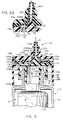
- Figure 1 is a persective view of an embodient of liquid nozzle assembly in accordance with the invention mounted on a liquid storage and dispensing container;
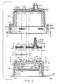
- Figure 2 is a sectional view taken along each of the lines indicated at 2-2 in Figures 1, 4 and 6;
- Figure 2A is an enlarged fragmentary view taken from Figure 2 and illustrating the deflection of the valve element to open the liquid dispensing conduit in the nozzle assembly;
- Figure 3 is an exploded, sectional view of the nozzle assembly in Figures 1 and 2;
- Figure 4 is a bottom plan view of the nozzle housing of the assembly as indicated by the line 4-4 in Figure 3;
- Figure 5 is a fragmentary, sectional view taken along the line 5-5 in Figure 4 and viewed in the indicated direction;
- Figure 6 is a top plan view of the diphragm element as indicated by the line 6-6 in Figure 3;
- Figure 7 is a top plan view of the filter element as indicated by the line 7-7 in Figure 3:
- Figure 8 is a top plan view of the adaptor element as indicated by the line 8-8 in Figure 3;
- Figure 9 is a vertical sectional view of a second embodiment of liquid nozzle assembly in accordance with the invention, mounted on a liquid storage and dispensing container;
- Figure 10 is a vertical sectional view of a third embodiment of liquid nozzle assembly in accordance with the invention, mounted on a liquid storage and dispensing container;
- Figure 11 is a top plan view of an integral combination diaphragm and air aspiration filter shown in Figure 10;
- Figure 12 is an enlarged fragmentary sectional view of a section of the diaphragm as indicated on the line 12-12 in Figure 11;
- Figure 13A is an enlarged, fragmentary sectional view of the nozzle assembly shown in Figure 10 and illustrating the flow path for air aspiration through the nozzle assembly; and
- Figure 13B is an enlarged, fragmentary sectional view similar to Figure 13A, which illustrates the liquid flow path through the nozzle assembly.
- Referring to Figures 1 and 2, an embodiment of nozzle assembly in accordance with the invention and designated generally by
reference character 10 is shown mounted on a moulded plastics bottle orliquid container 12 having a flexible orsqueezable wall 14 and containing liquid such as saline solution. As shown in Figure 2, thecontainer 12 opens at the top from aneck portion 16. A generallycylindrical adaptor 18 surrounds theneck portion 16. Theadaptor 18 includes an annularinternal flange 18a which projects downwardly into the opening at the top of theneck 16 and terminates in a radially flared annular projection 18aa which securely engages, and preferably forms a seal with, the interior surface of the neck. Theadaptor 18 has a medialcylindrical skirt 18b which has an inwardly extending annular lug 18c which is forced between a pair of adjacent radially outwardly extendingannular flanges adaptor 18 securely on thebottleneck 16 in a sealed condition. - A radially outwardly extending
annular flange 18d forms a shoulder at the bottom of a radially outermost skirt 18bb and theshoulder flange 18d forms a base on which a generally cylindrical nozzle housing orcap 20 is seated. Theflange 18d is a snap-fit and is clamped between anannular shoulder 20a of thenozzle housing 20 and an annular arrangement of six spacedarcuate cleat portions 20b projecting inwardly from a lowermostannular skirt portion 21 of thehousing 20 as shown in Figures 2-4. Also, theshoulder wall 20a is interrupted by an annular arrangement of six through-slots 23 which are respectively aligned with the sixcleats 20b;slots 23 provide tooling access for moulding the cleats. - Referring to Figures 2, 3 and 8, the
adaptor 18a includes a circular upper wall designated generally by 18e which is divided into separate portions providing for separate and distinct liquid dispensing conduit means and air aspiration conduit means. Theupper wall 18e also forms a base which seats ahydrophobic filter member 22 and a complex,elastomeric diaphragm 24 integrally moulded, for example from silicone rubber, as shown in Figures 2, 2A, 3 and 6. As best shown in Figures 3 and 8, theupper wall 18e of theadpater 18 has arecess 18f which peripherally conforms to and postions thediaphragm 24 as shown in Figure 6. As indicated in Figure 3 and shown in Figure 2, the filter member 22 (Figure 7) is seated and clamped within a left-hand portion of therecess 18f by a left-hand portion of the diaphragm 24 (i.e., left-hand as viewed in Figures 2, 6 and 8). As best shown in Figures 2 and 8, a medialarcuate bridging surface 18g within therecess 18f divides twodeeper recesses filter member 22; anarcuate slot 26 is formed through thewall 18e radially outside themedial skirt 18b, and extends into therecess 18h to form a portion of an intake conduit for air aspiration together with abore 28 from therecess 18i through thewall 18e, as more fully described hereinafter. - Referring to Figure 6 the
diaphragm 24 includes two thickened,peripheral beads small diaphragm web 24c. As shown in Figure 2, theseparate beads recess 18f by an inner surface of the upperciruclar cap wall 20c. Thecap wall 20c also has amoulded embossment 20d shown in Figure 4 which provides peripherally conformed surrounding engagement with the clamped diaphragm beads. A second, radillyinner embossment 20e is configured to fit within and position theoval bead 24b. As shown in Figures 2 and 6 thediaphragm 24 further includes a frustoconicaltubular nozzle portion 24d which integrally extends upwardly from a larger elastomeric, tubular column or valve portion 24dd. The interior surface of the columnar valve base portion 24dd fits loosely around anipple formation 18j projecting upwardly from theadaptor wall 18e to provide a conical, annular clearance space A therebetween as shown in Figures 2 and 2A. The clearance space A leads to the cental bore of thetubular portion 24d which provides at its upper end a discharge orifice for the liquid dispensing conduit as indicated by the arrow B and as more fully described hereinafter. Thetubular nozzle 24d is supported by a surroundingannular boss 20f whose lower surface seals against the annular upper surface 24ddd of the tubular base 24dd as shown in Figures 2 and 2A and more fully discussed hereinafter with the valve operation. - Referring again to Figure 8, two
bores 30 through theadaptor wall 18e adjacent thenipple 18j provide passageways for liquid flow in the liquid dispensing conduit as indicated by the arrow C in Figure 2 and leading to the clearance passageway A and then to discharge as indicated by the arrow B when a snap-fitting cover 18k is removed from thenozzle housing 20. Thecover 18k has a cup-like configuration and is connected by an integrally moulded connecting web orlanyard 18p which is flexible and joined to a portion of theannular adaptor shoulder 18d and passes through a notch 20dd formed in theskirt 21 of thenozzle housing 20 as best shown in Figure 1. - The tubular column or valve portion 24dd extends downwardly and terminates in a
tapered sealing ring 25 which normally seals, under compression by theboss 20f, against theadaptor wall 18e at its surface surrounding thenipple 18j to prevent leakage of the stored liquid (saline solution) even under hydrostatic pressure when the container is inverted in handling, and to prevent any backflow of non-sterile air or liquid from the clearance space A into thebottle neck 16. Backflow liquid is additionally prevented by the projection of the conicallyshaped nipple 18j into thetubular nozzle portion 24d in order to minimize the volume of liquid remaining in thetubular portion 24d when the dispensing flow has stopped. The small amount of remaining liquid in thetubular portion 24d, which can be exposed to contamination by air, will be flushed out before the next dispensing. - Referring to Figure 2A, when the
flexible wall 14 is squeezed to dispense the saline solution from the invertedcontainer 12 andnozzle assembly 10, the liquid flows through both the passageway bores 30 and exerts the necssary threshold hydraulic pressure against thediaphragm portion 24e which is resiliently deflected to compress further the tubular valve portion 24dd against theboss 20f; the additional compression of the valve portion 24dd thereby displaces and unseats sealingring 25 fromwall 18e to enable the liquid flow therebetween into the adjacent portion of the annular clearance space A (which is enlarged by the diaphragm deflection). The liquid flow through the clearance space A leads to discharge of the liquid through thetubular nozzle 24d as indicated by the arrow B. Thesealing ring 25 performs as a one-way valve allowing only outflow of dispensed liquid when theflexible wall 14 is squeezed, so that once the additional compression of the valve portion 24dd is relaxed when the manual squeeze is released, the residual compression of the valve portion 24dd will cause thesealing ring 25 to reseat and seal firmly against thewall 18e to close the one-way valve and prevent any backflow of liquid or air, for example, should the dispenser become exposed to non-sterile fluid such as by dropping into contaminated liquid. The valve portion column 24dd thus acts as an integral and elastomeric biasing spring on the sealingring 25. - The liquid flowing from the
bores 30 is constrained to enter the conical clearance space A by the circumscribing seal provided by the clampedoval diaphragm bead 24b. The seal provided by thediaphragm bead 24b is positioned and reinforced by aseating groove 18m and the two slightly projectingshoulders 18n which are formed within the adaptor recess 18f as shown in Figure 2 and best shown in Figure 8. Thecap wall 20c has a narrow vent groove 20i shown in Figures 2 and 4 which is located on the dry or non-liquid side above thediaphragm 24 to enable air displacement with the deflection of the diaphragm. - Referring to Figures 2 and 4, in order to aspirate air for reinflation of the squeezed
flexible wall 14 and to replace the liquid dispensed, ambient air is drawn under or around thehousing skirt 21 upwardly through the nozzle assembly and downwardly into thebottleneck 16. The detailed air flow path leads from theskirt 21 through theslot 26 and into therecess 18h as indicated by the series of upwardly pointing arrows D in Figure 2; from therecess 18h, the air passes through the left-hand portion of the hydrophobic and airpermeable filter membrane 22 as viewed in Figure 2. The upwardly flowing air from thefilter membrane 22 then flows through the two side-by-side apertures 24f (both of which are shown in Figure 6). From each of the apertures 24f the air passes into a respective one ofparallel groove channels 20g which are moulded into the lower surface of thehousing wall 20c as best shown in Figures 4 and 5. Thegroove channels 20g direct the horizontal flow of air above a medialtransverse bridge portion 24g of thediaphragm bead 24a. Thebead 24a andbridge 24g fit into acomplementary groove 20h in thehousing 20, shown in Figure 4. The air from bothgroove channels 20g flows through thediaphragm aperture 24h and then flows downwardly through thefilter membrane 22 again, whereupon the now twice-filtered air passes into therecess 18i and into thebore 28 leading to thebottleneck 16 for reinflation of theflexible wall 14. - The aspirating air is constrained to flow twice through the
filter membrane 22, as indicated by the arrows in Figure 2, by the clampeddiaphragm bead 24a which circumscribed both theair aspiration slot 26 and thebore 28. Thefilter membrane 22 itself is hydrophobic to prevent passage of liquid (saline solution) from thebore 28 when the liquid is dispensed through thebores 30. The filter membrane is also impermeable to bacteria so that the aspirating air is filtered twice to prevent entrained bacteria from contaminating the stored saline solution. The saline solution is therefore maintained in sterile condition within thecontainer 12 during repeated dispensing of the solution and air aspiration. Suitable air permeable hydrophobic filter material can be fabricated, for example, from supported acrylic copolymer treated with a siloxane composition such as the filter membrane material commercially available from Gelman Sciences in a particularly suitable composition designated Versapor-450 having a pore size of approximately 0.45 micron which is impenetrable to bacteria. - Referring to Figure 9, a second embodiment of nozzle assembly in accordance with the invention and designated generally by 110 is shown mounted on a moulded plastics bottle or
liquid container 112 having a flexible orsqueezable wall 114. Thecontainer 112 opens at the top from theneck portion 116. A generallycylindrical adaptor 118 of nozzle assembly surrounds theneck portion 116. Theadaptor 118 has an annular internal flange 118a which projects downwardly into the opening of theneck 116 and has a radially flared annular projection 118aa which seals securely against the interior surface of the neck. In this embodiment the sterile liquid L, such as saline solution, is contained within a flexibleinner bag 119 whose mouth 119a is sealed to the adaptor flange 118a so that thenozzle assembly 110 andbag 119 provide an integrally sealed container system with anelastomeric diaphragm 124 sealing out outside air and contamination fom the interior of thebag 119 and a sterile liquid L. Theelastomeric diaphragm 124 has a thickened, annularperipheral bead 124a which is clamped between an annular recess 118f in the upper surface of theadaptor 118 and a similarly mating recess in the inner surface of the overlying housing orcap 120. - The
cap 120 includes a downwardly extendingcylindrical skirt 120a which has an annular inwardly projecting lug 120b wedged below the outer periphery of theadaptor 118 which secures the clamping of the diaphragm. Theadaptor 118 has a radially outercylindrical skirt 118b which also has a radially inwardly extending annular lug 118bb which is forced between a pair of adjacentannular coupling flanges 116a, 116b which enable an interference fit with the lug 118bb therebetween to mount theadaptor 118 and thenozzle assembly 110 securely on thebottle neck 116 in sealed position. - The
diaphragm 124 includes atubular nozzle portion 124d which extends integrally upwardly from a larger elastomeric, tubular column or valve portion 124dd. The interior surface of the columnar valve portion 124dd fits loosely around a nipple formation 118j projecting upwardly from the adaptor wall 118e to provide a conical clearance space A therebetween. The clearance space A leads to the central bore of thetubular portion 124d which provides an orifice at its upper end for liquid discharge as indicated by arrow B. Thetubular nozzle 124d is supported by anannular boss 120f whose lower surface seals against the annular upper surface 124ddd of the tubular valve portion 124dd. A snap-fitting cover (not shown) can be provided to fit removably over thetubular nozzle 124d andboss 120f, similar to thecap 18k provided in the first embodiment of nozzle assembly. - The tubular column or valve portion 124dd extends downwardly and terminates in a
tapered sealing ring 125 which normally seals, under compression by theboss 120f, against the adaptor wall 118e at its surface surrounding the nipple 118j to prevent leakage of the stored liquid even under hydrostatic pressure when thecontainer 112 is inverted during handling, and to prevent any backflow of non-sterile air or liquid from the clearance space A into thebottle neck 116. Backflow of liquid is additionally prevented by the projecion of the conically shaped nipple 118j into thetubular nozzle portion 124d in order to minimise the volume of liquid remaining in thetubular portion 124d, when the dispensing flow is stopped. The small amount of remaining liquid in thetubular portion 124d which can be exposed to contamination by air, will be flushed out before the next dispensing. - When the
flexible container wall 114 is squeezed to dispense the saline solution L from theinverted container 112, the air pressure within the clearance space C between thebag 119 and thewall 114 is squeezed against thebag 119 which then collapses and displaces the liquid A through the adaptor flange 118a and then through the adaptor passageway bore 130. The liquid flowing from thebore 130 is constrained by thediaphragm 124 and exerts the necessary threshold hydraulic pressure against the annular diaphragm portion 124e which is resiliently deflected to further compress the tubular valve portion 124dd against theboss 120f. The additional compression of the valve portion 124dd thereby displaces and unseats the sealingring 125 from the wall 118e to enable the liquid flow therebetween into the adjacent portion of the annular clearance A which is enlarged by the diaphragm deflection as shown in the entirely corresponding partial structure illustrated in Figure 2A of the first embodiment of nozzle assembly. Thecap wall 120 has a narrow vent groove 120i which is located on the dry or non-liquid side above the outer portion of thediaphragm bead 124a to enable air displacement with the deflection of thediaphragm 124. - The liquid flow through the clearance space A leads to discharge of the liquid through the
tubular nozzle 124d as indicated by the arrow B. The sealingring 125 performs as a one-way valve allowing only outflow of dispensed liquid when theflexible wall 114 andbag 119 are squeezed, so that once the additional compression of the valve portion 124dd is relaxed when the manual squeeze is released, the residual compression of the valve portion 124dd will cause thesealing ring 125 to reseat and seal firmly against the wall 118e to close the one-way valve and prevent any backflow of liquid or air. Such backflow might otherwise occur, for example, should the dispenser become exposed to non-sterile fluid such as by dropping into contaminated liquid. The columnar valve portion 124dd thus acts as an integral and elastomeric biasing spring on thesealing ring 125. - In order to maintain the pressure in the expanding volume of the clearance space C as the liquid in the
bag 119 is progressively emptied with successive dispensings and increasing collapse of thebag 119, an air aspiration conduit is provided through the nozzle assembly 100 leading to the air clearance C. Accordingly, when the manual squeezing of thecontainer wall 114 is released, air enters the nozzle assembly 100 through anentrance passageway 126 through thecap 120 which downwardly directs the air to avalve seat 126a opening from the lower surface of thecap 120. Thediaphragm 124 has alatral extension portion 124f which seats on thevalve seat 126a to form a one-way valve which is normally closed, particularly when thecontainer wall 114 is squeezed and the air pressure in the clearance C is communicated against the interior surface of thediaphragm extension portion 124f. However, during air aspiration, thediaphragm extension 124f unseats from thevalve seat 126a to open the one-way flow of air around thediaphragm extension 124f so that the air flows through an axially alignedpassageway 127 through theadaptor 118 leading to a radially alignedpassageway 128 in theadaptor 118. The inner end of theradial passageway 128 opens into an axial bore 129 formed through theadaptor 118 adjacent to the outer surface of the cylindrical flange 118a. In order to prevent thediaphragm extension 124f from deflecting excessively against and otherwise closing theadaptor passageway 127, a pair ofsmall beads 127a or similar small projections are provided preferably adjacent the peripheral opening of thepassageway 127 in order to engage thediaphragm extension 124f when it is deflected during air aspiration and thus maintaining clearance for air entry into thepassageway 127. - From the bore 129 the aspirating air flows downwardly and is distributed annularly in the clearance space between the flange 118a and the
bottleneck 116 and then passes throughslots 131 formed through the annular lug 118aa leading to the air clearance C as indicated by the air flow path arrows D. The aspirating air never comes in contact with the sterile liquid L contained within the sealedbag 119, and therefore the entirely separate liquid dispensing flow path and air aspiration flow path enable elimination of any filtering of the aspirating air which need not be sterile. - Referring to Figure 10, a third embodiment of nozzle assembly in accordance with the invention and designated generally by 210 is shown mounted on a moulded plastics bottle container 212 for sterile liquid L with a
squeezable wall 214. The container 212 opens at the top from aneck portion 216. An adaptor portion 218 of the nozzle assembly generally closes the mouth of theneck 216 and has acylindrical wall 218a which projects downwardly into the opening of theneck 216 with a radially flared annular lug projection 218aa which seals securely against the interior surface of the neck. The upper surface of the adaptor 218 supports a partitionedelastomeric diaphragm 224 which includes integrally both anair filtering portion 224a and a valve element portion 224dd as more fully described hereinafter. Theelastomeric diaphragm 224 also includes a thickened annularperipheral bead 224b which is clamped between the upper surface of the adaptor 218 and the lower surface of an overlying housing orcap member 220. The circumferential periphery of the upper wall of the adaptor 218 is seated on an innerannular shelf 220a which projects radially inwardly from a downwardly extendingcylindrical skirt portion 220b of thecap 220. Theskirt 220b also has a radially inwardly projecting annular lug 220C which is forced between a pair of adjacent annular coupling flanges 216a and 216b which enable an interference fit of the lug 220C therebetween to secure the clamping of thediaphragm 224 and adaptor 218 on thebottleneck 216. - Referring particularly to Figures 11 and 12, the
air filter portion 224a of the integratedelastomeric diaphragm 224 can be an annulus of the filter material which is inserted during moulding of thediaphragm 224 from elastomeric material, for example, silicone rubber. The filter material is embedded and supported at its inner periphery by the diaphragm valve portion 224dd and at the outer periphery by thebead 224b so that the annular medial portion is exposed to form theair filter portion 224a; for added structural integrity, the filter material may be embedded withinradial ribs 224c of the elastomeric material. The filter membrane material of theportion 224a is hydrophobic to prevent passage of the sterile liquid L (saline solution) and is also impermeable to bacteria but is permeable to air so that the aspirating air is filtered to prevent entrained bacteria from contaminating the sterile liquid during aspiration as more fully described hereinafter. Suitable air permeable hydrophobic filter material for the diaphragmair filter portion 224a can be fabricated, for example, from supported acrylic copolymer treated with a siloxane composition such as the filter membrane material commercially available from Gelman Sciences in a particularly suitable composition designated Versapor-450 having a pore size of approximately 0.45 micron which is impenetrable by bacteria. - The
diaphragm 224 also includes atubular nozzle portion 224d which extends integrally upwardly from a larger elastomeric tubular column or valve portion 224dd. The interior surface of the columnar valve portion 224dd fits loosely aound a nipple formation 218j which projects upwardly from the upper wall of the adaptor 218 to provide a conical clearance space A therebetween as best shown in Figure 13B. The clearance space A leads to the central bore of thetubular portion 224d which has a liquid discharge orifice at its upper end indicated by arrow B. - The
tubular nozzle portion 224d is supported by an annular boss 220f whose lower surface seals against the annular upper surface 224ddd of the tubular valve portion 224dd. A snap-fitting cover 220g connected to cap 220 is provided to fit removably over thetubular nozzle 224d and boss 220f. - The tubular column or valve portion 224dd extends downwardly and terminates in a
tapered sealing ring 225 which normally seals, under compression by the boss 220f against the upper wall surface of the adaptor 218 closely surrounding the nipple 218j to prevent leakage of the stored liquid L even under hydrostatic pressure when the container 212 is inverted during handling, and to prevent any backflow of non-sterile air or liquid from the clearance space A into thebottle neck 216. Backflow of liquid is additionally prevented by the projection of the conically shaped nipple 218j into thetubular nozzle portion 224d in order to minimize the volume of liquid remaining in thetubular portion 224 when the dispensing flow is stopped The small amount of liquid remaining in thetubular portion 224d, which can be exposed to contamination by air, will be flushed out before the next dispensing. - Referring to Figures 10 and 13B, when the
flexible container wall 214 is squeezed to dispense the liquid L from the inverted container 212 thenozzle assembly 210, the liquid flows through the passageway bore 228 and exerts the necessary threshold hydraulic pressure against the liquid-impermeable filter portion 224a of thedisphragm 224 which is resiliently deflected to compress further the tubular valve portion 224dd against the boss 220f; the additional compression of the valve portion 224dd thereby displaces and unseats theannular sealing ring 225 from the surface of the adaptor 218 to enable the liquid flow therebetween into the adjacent portion of the annular clearance space A (which is enlarged by the diaphragm deflection). Thecap 220 has anarrow vent grove 220i as shown in Figure 10 which is located on the dry or non-liquid side above thediaphragm 224 to enable air displacement with the deflection of thediaphragm 224. - The liquid flow through the clearance space A leads to discharge of the liquid through the
tubular nozzle 224d as indicated by the arrow B. The elastomeric valve portion 224dd and sealingring 225 performs as a one-way valve allowing only outflow of dispensed liquid when theflexible container wall 214 is squeezed. Once the additional compression of the valve portion 224dd is relaxed when the manual squeeze is released, the residual compression of the valve portion 224dd will cause thesealing ring 225 to reseat and seal firmly against the wall of the adaptor 218 to close the one-way valve and prevent any backflow of liquid or air. Such backflow might otherwise occur, for example, should the dispenser become exposed to non-sterile fluids such as by dropping into contaminated liquid. The valve portion column 224dd thus acts as an integral and elastomeric biasing spring on theseaing ring 225. - Referring to Figure 13A, in order to asperate air for reinflation of the squeeze
flexible container wall 214 and to replace the liquid dispensed, ambient air is drawn into anentrance passageway 230 and is directed downwardly and filtered through thefilter portion 224a above the passageway bore 228 through which the air flows through the adaptor skirt 218 andcontainer neck 216. Thefilter portion 224a of thediaphragm 224 thus serves a dual function as both the aspiration air filter as well as the hydraulically deflectable portion of the diaphragm valving in the liquid dispensing conduit. Accordingly, the integration of the hydraulically deflectable air filter within the diaphragm structure enables a particularly uncomplicated flow path of the air aspiration conduit and a simplified nozzle assembly without jeopardizing contamination of the sterile liquid during storage and successive dispensing.
Claims (13)
- A liquid dispensing nozzle assembly (10; 110; 210) for mounting on a liquid container and dispenser (12; 112; 212) has a flexible wall (14; 114; 214) and liquid storage cavity for manually squeezed dispensing of liquid (L) from the cavity through the nozzle assembly (10; 110; 210) and for maintaining the liquid (L), such as contact lens saline solution, in sterile condition during storage and repeated dispensing of the liquid (L) from the container cavity, said nozzle assembly (10; 110; 210) comprising a liquid discharge port or orifice (B); liquid conduit means (30, A, 24; 228, A) for communication from the container cavity to said liquid discharge port (B) to enable dispensing of said liquid (L) through said port (B) during said manually squeezed liquid dispensing; and characterised in that said nozzle assembly (10) further comprises diaphragm means (24; 124) integrally including a deflectable valve element (25; 125) of a valve for biased sealing against a valve seat (18e; 118) in said nozzle assembly, forming a one-way valve therewith allowing only one-way flow of liquid (L) therebetween when said valve element (25; 125) is resiliently unseated from said valve seat (18e; 118) to open said valve, and a tubular portion (24d; 124d) intergrally formed with said valve element (25; 125) such that said resilient unseating of said valve element (25; 125) to open said valve permits said liquid flow past said valve element (25; 125) into said tubular portion (24d; 124d) for discharge therefrom, and said tubular portion (24d; 124d) includes an outwardly flared annular column portion (24dd; 124dd) formed at an end of said tubular portion (24d; 124d), wherein said column portion (24dd; 124dd) includes first and second generally axially opposing annular surfaces (25, 25X; 125, 125X) for compressed sealing against respective surfaces (18e, 24ddd; 118, 124ddd) of said nozzle assembly (10; 110), and wherein said first annular column surfaces (25; 125) defines said deflectable valve element.
- The nozzle assembly according to Claim 1, further characterised in that said diaphragm means (24; 124) further includes an elastomeric diaphragm portion (24e; 124e) peripherally secured to said column portion (24dd; 124dd) for exertion of hydraulic pressure of liquid (L) against said diaphragm portion (24e; 124e) in order to produce resilient deflection of said diaphragm portion (24e; 124e) and said resilient unseating of said valve element (25; 125) with said diaphragm deflection.
- The nozzle assembly according to Claim 2, further characterised in that said diaphragm portion (24e; 124e) includes an annular configuration peripherally joined to a generally cylindrical side surface of said column portion (24dd; 124dd).
- The nozzle assembly according to Claim 1 or Claim 2, further characterised by an air aspiration conduit means (26, 28, 18h, 24f; 126, 128) for aspirating air into said container (12) to replace the liquid (L) dispensed therefrom.
- The nozzle assembly according to Claim 4 further characterised in that said diaphragm means (24; 124) further integrally includes an aspiration portion (24h) within said air aspiration conduit means (26, 28, 18h, 24f).
- The nozzle assembly according to Claim 5, further characterised in that said aspiration portion (24h) comprises an air filter means (22) for preventing entrainment of bacteria with aspirating air flow through said air aspiration conduit means (26, 28, 18h, 24).
- The nozzle assembly according to Claim 6, wherein said air filter means (22) is impermeable to flow of said liquid (L) therethrough.
- The nozzle assembly according to Claim 6 or 7, wherein said air filter means (22) is deflectable under liquid flow pressure thereagainst during dispensing of said liquid (L) through said liquid conduit means (30, A, 24).
- The nozzle assembly according to any one of Claims 6 to 8, characterised in that said column portion (24dd) and said air filter means (22) are arranged adjacently within said diaphragm means (24) such that deflection of said air filter means (22) induces deflection and opening of said one-way valve (25) to enable passage of said liquid (L) therethrough during said liquid dispensing.
- The nozzle assembly according to any one of Claims 6 to 9, characterised in that said air filter means (22) is integrated by insertion during moulding of said diaphragm means (24).
- A valve structure for controlling liquid flow from a liquid dispensing nozzle assembly as defined in any one of Claims 1 to 10, in which a resiliently deflectable valve element (25; 125) provides biased seal against a valve seat (18j; 118) to form a one-way valve allowing only one-way flow of a liquid (L) from the liquid storage container (12) therebetween when the valve element (25; 125) is resiliently unseated from the valve seat (18j; 118) to open the valve, characterised in that: said valve element comprises a compressible column (24dd; 124ddd) having opposing axial end surfaces (25, 25X; 125, 125X) which are normally compressed against respective valve surfaces (18e, 20X; 118, 120X) on said nozzle structure including said valve seat (18e) for preventing said liquid flow through said valve, said column (24dd; 124dd) being further compressible to resiliently unseat one of said column end surfaces (25; 125) from said valve seat (18e; 118) to allow said one-way liquid flow while said opposing column end surface (25X; 125X) remains stationary and compressed against said respective valve surface (20X; 120X).
- A valve structure according to claim 11, further characterised by an elastomeric diaphragm member (24e; 124e) peripherally secured to said column (24dd; 124dd) for exertion of hydraulic pressure of liquid (L) against said diaphragm member (24e; 124e) in order to produce resilient deflection of said diaphragm member (24e; 124e) and said further compression of said column (24dd; 124dd) and said resilient unseating of said column end surface (25; 125) with said diaphragm deflection.
- A valve structure according to claim 12, further characterised in that said diaphragm member (24e; 124e) includes an annular configuration peripherally joined to a generally cylindrical side surface of said column (24dd; 124ddd) between said end surfaces thereof (25, 25X; 125, 125X).
Applications Claiming Priority (4)
| Application Number | Priority Date | Filing Date | Title |
|---|---|---|---|
| US25536588A | 1988-10-07 | 1988-10-07 | |
| US255365 | 1988-10-07 | ||
| US07/406,053 US5025957A (en) | 1988-10-07 | 1989-09-11 | Liquid dispenser nozzle assembly |
| US406053 | 1989-09-11 |
Related Parent Applications (1)
| Application Number | Title | Priority Date | Filing Date |
|---|---|---|---|
| EP89310141.0 Division | 1989-10-04 |
Publications (1)
| Publication Number | Publication Date |
|---|---|
| EP0575014A1 true EP0575014A1 (en) | 1993-12-22 |
Family
ID=26944643
Family Applications (3)
| Application Number | Title | Priority Date | Filing Date |
|---|---|---|---|
| EP19930201800 Withdrawn EP0575014A1 (en) | 1988-10-07 | 1989-10-04 | Liquid dispenser nozzle |
| EP19890310141 Expired - Lifetime EP0363172B1 (en) | 1988-10-07 | 1989-10-04 | Liquid dispenser nozzle assembly |
| EP19940200427 Expired - Lifetime EP0602019B1 (en) | 1988-10-07 | 1989-10-04 | Liquid dispenser nozzle |
Family Applications After (2)
| Application Number | Title | Priority Date | Filing Date |
|---|---|---|---|
| EP19890310141 Expired - Lifetime EP0363172B1 (en) | 1988-10-07 | 1989-10-04 | Liquid dispenser nozzle assembly |
| EP19940200427 Expired - Lifetime EP0602019B1 (en) | 1988-10-07 | 1989-10-04 | Liquid dispenser nozzle |
Country Status (7)
| Country | Link |
|---|---|
| US (1) | US5025957A (en) |
| EP (3) | EP0575014A1 (en) |
| JP (1) | JPH0694015B2 (en) |
| AU (1) | AU620292B2 (en) |
| CA (1) | CA1340719C (en) |
| DE (2) | DE68925260T2 (en) |
| ES (2) | ES2081305T3 (en) |
Cited By (2)
| Publication number | Priority date | Publication date | Assignee | Title |
|---|---|---|---|---|
| GB2333770A (en) * | 1998-01-30 | 1999-08-04 | Cannon Rubber Ltd | Closure assembly with a self-closing diaphragm valve |
| CN103974882A (en) * | 2011-10-13 | 2014-08-06 | 高级技术材料公司 | Liner-based shipping and dispensing containers for the substantially sterile storage, shipment, and dispense of materials |
Families Citing this family (76)
| Publication number | Priority date | Publication date | Assignee | Title |
|---|---|---|---|---|
| US6116281A (en) * | 1976-04-12 | 2000-09-12 | Mastromatteo; Michael | Control devices |
| US5320254A (en) * | 1988-10-07 | 1994-06-14 | Ryder International Corp. | Liquid dispenser nozzle assembly |
| US5431310A (en) * | 1988-10-07 | 1995-07-11 | Ryder International Corporation | Liquid dispenser nozzle assembly |
| US5183184A (en) * | 1988-10-07 | 1993-02-02 | Ryder International Corporation | Liquid dispenser nozzle assembly |
| US5074440A (en) * | 1990-07-16 | 1991-12-24 | Alcon Laboratories, Inc. | Container for dispensing preservative-free preparations |
| DE4027539A1 (en) * | 1990-08-31 | 1992-03-05 | Kautex Werke Gmbh | Squeeze bottle with inner bag |
| CA2025105A1 (en) * | 1990-09-11 | 1992-03-12 | Garth T. Webb | Device for storing and dispensing sterile liquids |
| US5507417A (en) * | 1990-09-11 | 1996-04-16 | Webb Garth T | Device for storing and dispensing sterile liquids |
| US5154325A (en) * | 1991-01-09 | 1992-10-13 | Ryder International Corporation | Solution delivery nozzle and system with antimicrobial features |
| US5238153A (en) * | 1991-02-19 | 1993-08-24 | Pilkington Visioncare Inc. | Dispenser for dispersing sterile solutions |
| US5373972A (en) * | 1991-11-15 | 1994-12-20 | Jsp Partners, L.P. | Preservative-free sterile fluid dispensing system |
| US5310094A (en) * | 1991-11-15 | 1994-05-10 | Jsp Partners, L.P. | Preservative free sterile fluid dispensing system |
| WO1993010852A1 (en) * | 1991-12-02 | 1993-06-10 | Self-Instill & Co., Inc. | Apparatus for applying medicament to an eye |
| US5460834A (en) * | 1991-12-13 | 1995-10-24 | Alcon Laboratories, Inc. | Combinations of polymers for use in physiological tear compositions |
| EP0546728A3 (en) * | 1991-12-13 | 1993-09-08 | Alcon Laboratories Inc | Physiological tear compositions and methods for their preparation |
| AU661353B2 (en) * | 1991-12-24 | 1995-07-20 | Ryder International Corporation | Dispemser container with integrally head formed segment |
| US5267986A (en) | 1992-04-06 | 1993-12-07 | Self-Instill & Co., Inc. | Cartridge for applying medicament to an eye from a dispenser |
| EP0735852B1 (en) * | 1993-12-20 | 1999-09-22 | Biopolymerix, Inc. | Liquid dispenser for sterile solutions |
| US5849311A (en) * | 1996-10-28 | 1998-12-15 | Biopolymerix, Inc. | Contact-killing non-leaching antimicrobial materials |
| US5817325A (en) * | 1996-10-28 | 1998-10-06 | Biopolymerix, Inc. | Contact-killing antimicrobial devices |
| US5490938A (en) * | 1993-12-20 | 1996-02-13 | Biopolymerix, Inc. | Liquid dispenser for sterile solutions |
| JP3693411B2 (en) * | 1995-08-21 | 2005-09-07 | 花王株式会社 | container |
| DE19610457A1 (en) * | 1996-03-16 | 1997-09-18 | Pfeiffer Erich Gmbh & Co Kg | Discharge device for media |
| US5752629A (en) * | 1996-04-12 | 1998-05-19 | The Procter & Gamble Company | Passive venting for pump dispensing device |
| US5692651A (en) * | 1996-06-06 | 1997-12-02 | Owens-Illinois Closure Inc. | Self-sealing dispensing closure |
| DE19627228A1 (en) * | 1996-07-05 | 1998-01-08 | Pfeiffer Erich Gmbh & Co Kg | Discharge device for media |
| FR2761665B1 (en) * | 1997-04-02 | 1999-06-25 | Sofab | DEVICE FOR DISPENSING AND PACKAGING STERILE LIQUID PRODUCTS |
| US5950878A (en) * | 1997-08-04 | 1999-09-14 | Steris Corporation | Dispensing tube valve assembly |
| FR2771296B1 (en) * | 1997-11-25 | 2000-03-10 | Sofab | NASAL TIP WITH END CLOSURE |
| US6006952A (en) * | 1998-02-06 | 1999-12-28 | Lucas; Monty J. | Sports bottle |
| GB2344857B (en) * | 1998-12-15 | 2001-03-14 | Bespak Plc | Improvements in or relating to dispensing apparatus |
| FR2798368B1 (en) * | 1999-09-09 | 2001-11-23 | Valois Sa | IMPROVED FLUID PRODUCT DISPENSING PUMP, AND FLUID PRODUCT DISPENSING DEVICE COMPRISING SUCH A PUMP |
| JP4580524B2 (en) * | 2000-09-12 | 2010-11-17 | 株式会社日本点眼薬研究所 | Discharge container with filter |
| FR2821766B1 (en) * | 2001-03-07 | 2003-10-24 | Airlessystems | POCKET FLUID COSMETIC PRODUCT DISPENSER |
| DE10200519A1 (en) | 2002-01-09 | 2003-07-10 | Neomed Holding Sa Luxemburg Lu | Valve |
| DE10217655B4 (en) * | 2002-04-19 | 2004-05-27 | Gaplast Gmbh | One-way valve for dispensing a flowable material |
| ES2543009T3 (en) * | 2002-08-13 | 2015-08-13 | Medical Instill Technologies, Inc. | Container and valve assembly for storing and distributing substances and related method |
| CA2520921A1 (en) * | 2003-03-31 | 2004-10-21 | Nick J. Manesis | Multi-dose liquid dispensing assembly |
| FR2862052B1 (en) * | 2003-11-10 | 2006-02-17 | Rexam Pharma | MICROFILTRANT MENBRANES LIQUID CONDITIONING AND DISPENSING ASSEMBLY |
| US20100108712A1 (en) * | 2005-09-30 | 2010-05-06 | Manesis Nick J | Multi-dose liquid dispensing assembly |
| DE602008000505D1 (en) * | 2007-10-18 | 2010-02-25 | Bausch & Lomb | Closure arrangement with tilting lid opening mechanism |
| EP2077132A1 (en) | 2008-01-02 | 2009-07-08 | Boehringer Ingelheim Pharma GmbH & Co. KG | Dispensing device, storage device and method for dispensing a formulation |
| FR2929249B1 (en) | 2008-03-27 | 2012-02-17 | Rexam Pharma La Verpilliere | DEVICE FOR DISPENSING LIQUID CONTAINED IN A RESERVOIR |
| US9433960B2 (en) * | 2008-09-01 | 2016-09-06 | Rieke Corporation | Liquid dosing devices |
| FR2937019B1 (en) | 2008-10-15 | 2012-06-08 | Rexam Pharma La Verpilliere | LIQUID DISPENSING DEVICE WITH SEALING BODY HAVING AN ELASTOMERIC PART |
| US10011906B2 (en) | 2009-03-31 | 2018-07-03 | Beohringer Ingelheim International Gmbh | Method for coating a surface of a component |
| WO2010131042A1 (en) * | 2009-05-14 | 2010-11-18 | Leafgreen Limited | A precompression valve and fluid device comprising such a valve |
| EP2432531B1 (en) | 2009-05-18 | 2019-03-06 | Boehringer Ingelheim International GmbH | Adapter, inhalation device and nebulizer |
| FR2950037B1 (en) * | 2009-09-11 | 2011-12-16 | Rexam Pharma La Verpilliere | DEVICE FOR DISTRIBUTING LIQUID |
| FR2950036B1 (en) * | 2009-09-11 | 2011-12-16 | Rexam Pharma La Verpilliere | DEVICE FOR DISTRIBUTING LIQUID |
| DE102009048476B3 (en) * | 2009-10-07 | 2010-09-16 | Gaplast Gmbh | One-way valve for releasing liquid from container, has outer cap which is mounted at container neck, and outlet channel is provided for fluid, where valve body is made of elastic material, and is arranged between container and outer cap |
| FR2952040B1 (en) * | 2009-10-29 | 2011-12-30 | Rexam Pharma La Verpilliere | DEVICE FOR DISPENSING LIQUID IN THE FORM OF DROPS |
| US10016568B2 (en) * | 2009-11-25 | 2018-07-10 | Boehringer Ingelheim International Gmbh | Nebulizer |
| WO2011064164A1 (en) | 2009-11-25 | 2011-06-03 | Boehringer Ingelheim International Gmbh | Nebulizer |
| WO2011064163A1 (en) | 2009-11-25 | 2011-06-03 | Boehringer Ingelheim International Gmbh | Nebulizer |
| US9943654B2 (en) | 2010-06-24 | 2018-04-17 | Boehringer Ingelheim International Gmbh | Nebulizer |
| WO2012130757A1 (en) | 2011-04-01 | 2012-10-04 | Boehringer Ingelheim International Gmbh | Medical device comprising a container |
| EP2710339B1 (en) * | 2011-05-18 | 2020-10-28 | Nigel Kelly | Fluid dispenser |
| US9827384B2 (en) | 2011-05-23 | 2017-11-28 | Boehringer Ingelheim International Gmbh | Nebulizer |
| BR112014017870A8 (en) * | 2012-01-20 | 2017-07-11 | Py Dr Inst Llc | DEVICE WITH COMFORTABLE CLOSURE, ONE-WAY VALVE, VARIABLE VOLUME STORAGE CHAMBER AND BRIEF ANTI-JET FEATURE AND RELATED METHOD |
| WO2013152894A1 (en) | 2012-04-13 | 2013-10-17 | Boehringer Ingelheim International Gmbh | Atomiser with coding means |
| WO2015018901A1 (en) * | 2013-08-09 | 2015-02-12 | Boehringer Ingelheim International Gmbh | Nebulizer |
| PL2835146T3 (en) | 2013-08-09 | 2021-04-06 | Boehringer Ingelheim International Gmbh | Nebulizer |
| US9744313B2 (en) | 2013-08-09 | 2017-08-29 | Boehringer Ingelheim International Gmbh | Nebulizer |
| FR3019475B1 (en) * | 2014-04-08 | 2021-10-15 | Albea Le Treport | DISTRIBUTION MODULE OF A PRODUCT INTENDED TO BE MOUNTED ON A DUCT SUPPLIED UNDER PRESSURE OF THE SAID PRODUCT |
| JP6559157B2 (en) | 2014-05-07 | 2019-08-14 | ベーリンガー インゲルハイム インターナショナル ゲゼルシャフト ミット ベシュレンクテル ハフツング | Nebulizer |
| SG10201709354PA (en) | 2014-05-07 | 2018-01-30 | Boehringer Ingelheim Int | Nebulizer, Indicator Device And Container |
| AU2015257878B2 (en) | 2014-05-07 | 2019-08-08 | Boehringer Ingelheim International Gmbh | Container, nebulizer and use |
| CN107106325B (en) | 2015-01-12 | 2021-05-25 | 科达莱昂治疗公司 | Droplet delivery apparatus and method |
| USD841471S1 (en) | 2017-02-24 | 2019-02-26 | S. C. Johnson & Son, Inc. | Bottle |
| USD845135S1 (en) | 2017-02-24 | 2019-04-09 | S. C. Johnson & Son, Inc. | Bottle neck with cap |
| US11679028B2 (en) * | 2019-03-06 | 2023-06-20 | Novartis Ag | Multi-dose ocular fluid delivery system |
| US20210137732A1 (en) * | 2019-03-06 | 2021-05-13 | Kedalion Therapeutics, Inc. | Vented Multi-dose Ocular Fluid Delivery System |
| WO2021212033A1 (en) | 2020-04-17 | 2021-10-21 | Kedallon Therapeutics, Inc. | Hydrodynamically actuated preservative free dispensing system |
| US11938057B2 (en) | 2020-04-17 | 2024-03-26 | Bausch + Lomb Ireland Limited | Hydrodynamically actuated preservative free dispensing system |
| WO2023215705A2 (en) * | 2022-05-02 | 2023-11-09 | Novartis Ag | Vented multi-dose ocular fluid delivery system |
Citations (5)
| Publication number | Priority date | Publication date | Assignee | Title |
|---|---|---|---|---|
| US2628004A (en) * | 1951-03-15 | 1953-02-10 | Theodore F Schlicksupp | Self-closing collapsible tube |
| US3321114A (en) * | 1966-03-04 | 1967-05-23 | Rexall Drug Chemical | Pop-up diaphragm closure |
| FR2266640A1 (en) * | 1974-04-08 | 1975-10-31 | Nilson Billy | |
| GB2106877A (en) * | 1981-08-17 | 1983-04-20 | Eugene Meierhoefer | Sterile solution delivery and venting device |
| US4917271A (en) * | 1988-10-07 | 1990-04-17 | Ryder International Corporation | Liquid dispensing nozzle assembly with filter |
Family Cites Families (13)
| Publication number | Priority date | Publication date | Assignee | Title |
|---|---|---|---|---|
| US4002168A (en) * | 1975-04-24 | 1977-01-11 | Tor Petterson | Method of, and dispenser for introducing an opthalmic product into the occular cavity |
| FR2347107A1 (en) * | 1976-04-06 | 1977-11-04 | Ciba Geigy Ag | Pumping action aerosol spray - has mushroom shaped resilient valve in discharge block with discharge channels between them |
| FR2368306A2 (en) * | 1976-10-20 | 1978-05-19 | Oreal | VAPORIZER BOTTLE WITH AIR INTAKE VALVE |
| US4057177A (en) * | 1977-01-18 | 1977-11-08 | Laauwe Robert H | Valved squeeze bottle for viscous products |
| US4102476A (en) * | 1977-02-22 | 1978-07-25 | Ciba-Geigy Corporation | Squeeze bottle dispenser with air check valve on cover |
| US4186882A (en) * | 1977-12-08 | 1980-02-05 | Harry Szczepanski | Atomizing liquid dispenser |
| US4420101A (en) * | 1981-11-18 | 1983-12-13 | Diamond International Corp. | Squeeze bottle with self-venting dispensing closure |
| US4513891A (en) * | 1982-04-15 | 1985-04-30 | Sterling Drug Inc. | Spray dispensing container and valve therefor |
| US4478356A (en) * | 1982-06-24 | 1984-10-23 | Essex Chemical Corporation | Flexible-bag self-closing metering dispensing valve |
| US4474314A (en) * | 1982-06-29 | 1984-10-02 | Essex Chemical Corporation | Squeeze bottle self-closing viscous liquid dispensing valve having manually operated positive shut-off |
| US4739906A (en) * | 1986-07-14 | 1988-04-26 | Blairex Laboratories, Inc. | Storage bottle for contact lens cleaning solution having a self closing valve assembly |
| JPH0446845Y2 (en) * | 1986-08-08 | 1992-11-05 | ||
| US4930667A (en) * | 1989-01-23 | 1990-06-05 | Steiner Company, Inc. | Breathing device for soap dispenser |
-
1989
- 1989-09-11 US US07/406,053 patent/US5025957A/en not_active Expired - Lifetime
- 1989-09-29 CA CA 614622 patent/CA1340719C/en not_active Expired - Fee Related
- 1989-10-04 ES ES89310141T patent/ES2081305T3/en not_active Expired - Lifetime
- 1989-10-04 EP EP19930201800 patent/EP0575014A1/en not_active Withdrawn
- 1989-10-04 EP EP19890310141 patent/EP0363172B1/en not_active Expired - Lifetime
- 1989-10-04 DE DE1989625260 patent/DE68925260T2/en not_active Expired - Fee Related
- 1989-10-04 EP EP19940200427 patent/EP0602019B1/en not_active Expired - Lifetime
- 1989-10-04 DE DE1989628940 patent/DE68928940T2/en not_active Expired - Fee Related
- 1989-10-04 ES ES94200427T patent/ES2128502T3/en not_active Expired - Lifetime
- 1989-10-06 AU AU42604/89A patent/AU620292B2/en not_active Ceased
- 1989-10-06 JP JP26190289A patent/JPH0694015B2/en not_active Expired - Lifetime
Patent Citations (5)
| Publication number | Priority date | Publication date | Assignee | Title |
|---|---|---|---|---|
| US2628004A (en) * | 1951-03-15 | 1953-02-10 | Theodore F Schlicksupp | Self-closing collapsible tube |
| US3321114A (en) * | 1966-03-04 | 1967-05-23 | Rexall Drug Chemical | Pop-up diaphragm closure |
| FR2266640A1 (en) * | 1974-04-08 | 1975-10-31 | Nilson Billy | |
| GB2106877A (en) * | 1981-08-17 | 1983-04-20 | Eugene Meierhoefer | Sterile solution delivery and venting device |
| US4917271A (en) * | 1988-10-07 | 1990-04-17 | Ryder International Corporation | Liquid dispensing nozzle assembly with filter |
Cited By (6)
| Publication number | Priority date | Publication date | Assignee | Title |
|---|---|---|---|---|
| GB2333770A (en) * | 1998-01-30 | 1999-08-04 | Cannon Rubber Ltd | Closure assembly with a self-closing diaphragm valve |
| GB2333770B (en) * | 1998-01-30 | 2000-06-14 | Cannon Rubber Ltd | Closure assembly for drinking vessel |
| US6305570B1 (en) | 1998-01-30 | 2001-10-23 | Cannon Rubber Limited, A British Company | Closure assembly for a drinking vessel |
| CN103974882A (en) * | 2011-10-13 | 2014-08-06 | 高级技术材料公司 | Liner-based shipping and dispensing containers for the substantially sterile storage, shipment, and dispense of materials |
| EP2766281A4 (en) * | 2011-10-13 | 2015-05-27 | Advanced Tech Materials | Liner-based shipping and dispensing containers for the substantially sterile storage, shipment, and dispense of materials |
| CN103974882B (en) * | 2011-10-13 | 2016-05-04 | 高级技术材料公司 | For the roughly transport based on liner and the dispense container of aseptic storage, transport and distribution of material |
Also Published As
| Publication number | Publication date |
|---|---|
| JPH0694015B2 (en) | 1994-11-24 |
| DE68925260D1 (en) | 1996-02-08 |
| EP0602019B1 (en) | 1999-03-03 |
| EP0363172B1 (en) | 1995-12-27 |
| CA1340719C (en) | 1999-08-24 |
| JPH02180659A (en) | 1990-07-13 |
| EP0602019A3 (en) | 1994-08-10 |
| DE68928940D1 (en) | 1999-04-08 |
| EP0602019A2 (en) | 1994-06-15 |
| AU620292B2 (en) | 1992-02-13 |
| ES2081305T3 (en) | 1996-03-01 |
| DE68925260T2 (en) | 1996-08-01 |
| ES2128502T3 (en) | 1999-05-16 |
| EP0363172A2 (en) | 1990-04-11 |
| EP0363172A3 (en) | 1990-12-27 |
| US5025957A (en) | 1991-06-25 |
| AU4260489A (en) | 1990-04-12 |
| DE68928940T2 (en) | 1999-07-01 |
Similar Documents
| Publication | Publication Date | Title |
|---|---|---|
| EP0602019B1 (en) | Liquid dispenser nozzle | |
| US5183184A (en) | Liquid dispenser nozzle assembly | |
| US5320254A (en) | Liquid dispenser nozzle assembly | |
| US5154325A (en) | Solution delivery nozzle and system with antimicrobial features | |
| US5431310A (en) | Liquid dispenser nozzle assembly | |
| EP0500249B1 (en) | Dispenser | |
| US4917271A (en) | Liquid dispensing nozzle assembly with filter | |
| US5255826A (en) | Liquid dispenser nozzle assembly | |
| EP1841662B1 (en) | Leak resistant drinking cup | |
| EP0253495B1 (en) | Storage bottle for contact lens cleaning solution | |
| US5240149A (en) | Closure cap | |
| US5725132A (en) | Dispenser with snap-fit container connection | |
| EP0207715A1 (en) | Vented discharge assembly for liquid soap dispenser | |
| CA2369601A1 (en) | A valved dispensing system with priming liquid loss prevention | |
| WO1991013812A1 (en) | Squeezable dispenser apparatus | |
| JP2002544444A (en) | Dispensing system with valve to protect valve from hydraulic hammer | |
| JP2008526636A (en) | Flow control element and distribution structure incorporating the same |
Legal Events
| Date | Code | Title | Description |
|---|---|---|---|
| PUAI | Public reference made under article 153(3) epc to a published international application that has entered the european phase |
Free format text: ORIGINAL CODE: 0009012 |
|
| AC | Divisional application: reference to earlier application |
Ref document number: 363172 Country of ref document: EP |
|
| AK | Designated contracting states |
Kind code of ref document: A1 Designated state(s): BE CH DE ES FR GB IT LI SE |
|
| STAA | Information on the status of an ep patent application or granted ep patent |
Free format text: STATUS: THE APPLICATION IS DEEMED TO BE WITHDRAWN |
|
| 18D | Application deemed to be withdrawn |
Effective date: 19940623 |