EP0576178A2 - Method of maintaining relationships between elements - Google Patents
Method of maintaining relationships between elements Download PDFInfo
- Publication number
- EP0576178A2 EP0576178A2 EP93304530A EP93304530A EP0576178A2 EP 0576178 A2 EP0576178 A2 EP 0576178A2 EP 93304530 A EP93304530 A EP 93304530A EP 93304530 A EP93304530 A EP 93304530A EP 0576178 A2 EP0576178 A2 EP 0576178A2
- Authority
- EP
- European Patent Office
- Prior art keywords
- creating
- graphical elements
- substep
- criteria includes
- alignment
- Prior art date
- Legal status (The legal status is an assumption and is not a legal conclusion. Google has not performed a legal analysis and makes no representation as to the accuracy of the status listed.)
- Granted
Links
Images


Classifications
-
- G—PHYSICS
- G06—COMPUTING; CALCULATING OR COUNTING
- G06T—IMAGE DATA PROCESSING OR GENERATION, IN GENERAL
- G06T11/00—2D [Two Dimensional] image generation
- G06T11/60—Editing figures and text; Combining figures or text
-
- Y—GENERAL TAGGING OF NEW TECHNOLOGICAL DEVELOPMENTS; GENERAL TAGGING OF CROSS-SECTIONAL TECHNOLOGIES SPANNING OVER SEVERAL SECTIONS OF THE IPC; TECHNICAL SUBJECTS COVERED BY FORMER USPC CROSS-REFERENCE ART COLLECTIONS [XRACs] AND DIGESTS
- Y10—TECHNICAL SUBJECTS COVERED BY FORMER USPC
- Y10S—TECHNICAL SUBJECTS COVERED BY FORMER USPC CROSS-REFERENCE ART COLLECTIONS [XRACs] AND DIGESTS
- Y10S715/00—Data processing: presentation processing of document, operator interface processing, and screen saver display processing
- Y10S715/961—Operator interface with visual structure or function dictated by intended use
Abstract
Description
- This invention generally relates to computer drawing programs and, more specifically, to a system and method for specifying graphical alignment and distribution criteria between graphical elements to be displayed and/or printed.
- A number of currently available desktop publishing and other computer programs allow a user to draw and manipulate graphical elements within a document. The ability to draw and manipulate graphical elements has become increasingly important because the use of organizational charts, data tables, bar charts and other graphical aids continues to increase as information purveyors attempt to communicate extensive and often detailed facts, figures and other concepts. Examples of currently available programs having graphical elements, drawing and manipulating capabilities include SuperPaint® from Silicon Beach Software, MacDraw™ from Claris Corporation, Canvas™ from the Deneba Corporation, and PageMake® from Aldus Corporation.
- A primary goal of users of programs having drawing and manipulating capabilities is to input, manipulate and present (on-screen or through an output device) graphical elements as efficiently as possible. Currently available programs generally include alignment features that allow graphical elements to be precisely aligned and spaced relative to one another. However, once the alignment command is executed, the user is free to move the graphical elements out of alignment. This presents a significant disadvantage during editing, because a user is required to continually apply alignment commands to ensure that graphical elements remain aligned and spaced as desired during editing. Thus, it would be advantageous to have a way of establishing a persistent relationship between graphical elements that keeps selected graphical elements aligned and spaced despite further editing or modification of graphical or other elements before a document is printed.
- The present invention is a method of specifying spatial relationships of elements in a graphics environment. The method includes the steps of (a) creating a distribution frame; (b) specifying a set of elements to be linked by the distribution frame; and (c) selecting alignment and distribution criteria that determine spatial relationships between the elements in the set and the distribution frame. In this manner the spatial relationships specified between each element is maintained throughout modification and editing of the elements.
- In accordance with other aspects of the invention, the method of selecting alignment and distribution criteria further includes selecting spatial relationships for the set of elements along a vertical axis and selecting spatial relationships for the set of elements along a horizontal axis.
- In accordance with further aspects of the invention, the method further includes selecting resizing options wherein the distribution frame is sized to fit the set of elements. Other resizing options that may be selected include sizing the elements within the set to fit the distribution frame. The resizing options may be implemented both vertically and horizontally. Further spacing criteria may be designated between the elements. Another feature of the invention is that the order of elements in the distribution frame may be locked such that they cannot be rearranged within the frame.
- In accordance with still further aspects of the invention, a method for solving constraints between graphical elements includes (a) creating a link between pairs of elements that are to be coupled by a constraint; (b) creating a dirty list of links whose constraints are not currently satisfied; (c) assigning a priority to each link in the dirty list that indicates a link whose constraint is to be solved first; and (d) solving the constraint associated with the link having the highest priority by changing the attributes of one of the graphical elements attached to the link.
- The foregoing features and advantages of the invention will become better understood by reference to the following detailed description, when taken in conjunction with the accompanying drawings, wherein:
- FIGURE 1 is a block diagram of a graphical applications program formed in accordance with the invention;
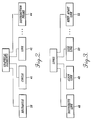
- FIGURE 2 is a hierarchical diagram depicting exemplary graphical elements;
- FIGURE 3 is a hierarchical diagram depicting exemplary constraints, referred to as links throughout this disclosure;
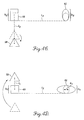
- FIGURE 4A is a pictorial diagram illustrating examples of the constraints that may be imposed on a set of graphical elements;
- FIGURES 4B-4D are pictorial diagrams of the graphical elements depicted in FIGURE 4A showing what occurs as a result of the imposed constraints;
- FIGURE 5 is a pictorial representation of a link pull-down menu illustrating exemplary constraint features that may be implemented in accordance with the invention;
- FIGURE 6 is a pictorial representation of a Link Browser feature having the constraint relationships set forth in FIGURE 4A;
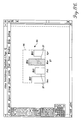
- FIGURE 7 is a pictorial representation of an Align/Distribute Frame dialog tool that may be used to create constraint relationships between graphical objects in accordance with the invention;
- FIGURES 8A-8C illustrate a series of bar charts that may be created and edited using a distribution frame in accordance with the invention;
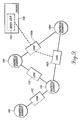
- FIGURE 9 is a constraint graph illustrating the addition of links to a dirty list after a graphical element has been edited;
- FIGURE 10 is a flow chart of a routine by which constraints are solved in accordance with the invention;
- FIGURE 11 is a flow chart of a routine for determining a resolve direction for any particular link;
- FIGURE 12 is a flow diagram of a routine for determining which of two graphical elements coupled to a link should be modified to meet the link constraint;
- FIGURE 13 is a flow diagram of a routine for adding graphical elements to the dirty list;
- FIGURE 14 is a flow diagram of a routine for resolving links that are coupled to a distribution frame;
- FIGURE 15 is a hierarchical diagram illustrating the data flow used to arrange graphical elements that are linked to a distribution frame; and
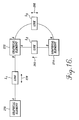
- FIGURE 16 is a block diagram of a set of graphical elements for use in explaining the operation of the constraint engine.
- A
graphical applications program 20 for specifying alignment and distribution criteria between graphical elements is shown generally in FIGURE 1. Thegraphical applications program 20 runs on a central processing unit (CPU) 22 controlled by anoperating system 24. Amemory 26 is connected to the CPU and generally comprises, for example, random access memory (RAM), read only memory (ROM), and magnetic storage media such as a hard drive, floppy disk, or magnetic tape. TheCPU 22 may be housed within a personal computer, minicomputer, or a mainframe (with one or more users), as the benefits and functionality of thegraphical applications program 20 may be implemented on a number of types of computers. In order to avoid unduly complicating this description, reference in the specification and drawings is generally made to personal computers and their operating systems. In this regard, a graphical applications program formed in accordance with this invention may, for example, run on Macintosh™, International Business Machine (IBM™) and IBM™ compatible personal computers. When used with IBM™ and IBM™ compatible personal computers, theoperating system 24 may utilize a windowing environment such as Microsoft Windows™. - The
graphical applications program 20 includes auser interface 28 that interacts with theoperating system 24 through anapplication shell 30. Coupled between theuser interface 28 andoperating system 24 are adocument engine 32, agraphics engine 34 and a constraint engine 36. Software program "engines" are generally defined as the portions of a program that determine how the program manages and manipulates data. Thedocument engine 32 manages a display list that contains a list of all of the graphical elements in a document. In addition, thedocument engine 34 saves and continually updates an element database that includes a set of "values" for each graphical element. The values of a graphical element determines attributes such as its shape, size, color, etc. Throughout the specification and in the claims, the term "graphical element" is used to generally refer to display objects and other objects, for example, nonprinting objects, which may be manipulated by the graphical applications program. Thegraphics engine 34 utilizes the values stored within the element database of the document engine to render or display the graphical elements on a cathode-ray tube or other output device. Because thedocument engine 32 andgraphics engine 34 can be implemented using technology that is generally known to those skilled in the art, the details of these engines are not described here. - FIGURE 2 illustrates a subset of some of the graphical elements that may be created using the
graphical applications program 20. Included are arectangle 38, acircle 40, aline 42 and adistribution frame 44. The rectangle, circle and line are all printable display objects. Thedistribution frame 44 is a nonprintable graphical element that comprises an area surrounded by a boundary which is preferably rectangular in shape. A distribution frame is considered to be a nonprinting graphical element because it will only appear when the user is editing a document but will not appear when the document is sent to an output device. Graphical elements positioned within the distribution frame are governed by alignment and distribution criteria set up for the frame. Thedistribution frame 44 and its attributes are discussed more fully below. - With reference again to FIGURE 1, the constraint engine 36 utilizes "links" to specify spatial relationships, i.e., constraints, between graphical elements. Spatial relationships between graphical elements may take on a variety of forms, and are specified by the user through the user interface. Links are generally not seen by the user and act as message carriers among graphical elements. Links can, however, be displayed and printed to allow the user to fully understand and control links that have been established between graphical elements. The links provide persistence between graphical elements, in that the constraint relationship imposed on two graphical elements by a link must be maintained throughout editing of the elements.
- With reference to FIGURE 3, a subset of four exemplary links are illustrated from the various links available in the graphical applications program. From left to right, the subset includes a distribute
link 46, analign link 48, asize link 50 and a keep-apartlink 52. The distributelink 46 is used to link graphical elements to a distribution frame. Thealign link 48 specifies how two graphical elements are to be aligned relative to one another. For example, the align link can be used to align two elements vertically by their centers. Thesize link 50 may be used to establish a size relationship such that if the size of one graphical element changes, the linked graphical element follows suit. The keep-apartlink 52 is a constraint requiring that a specified distance be maintained between two graphical elements, but outside of this distance the elements can be freely moved relative to one another. - FIGURES 4A-4D illustrate an exemplary, three-element spatial arrangement within a document showing some of the constraint features of the
graphical applications program 20. At the outset, it should be realized that the minimum number of links needed to couple N elements together is generally N - 1, although a greater number of links may always be utilized, thereby adding additional constraint relationships between pairs of graphical elements. - With reference to FIGURE 4A, a set of three graphical elements--a
triangle 58, arectangle 60, and an oval 62--are coupled together through the spatial relationships specified with threelinks triangle 58 to therectangle 60 by a constraint that requires that their centers remain vertically aligned. Thus, during editing of the document, any horizontal movement of thetriangle 58 will be tracked by therectangle 60, and vice versa. However, vertical movement of either graphical element will not affect the other because the centers remain aligned along the vertical axis.Links rectangle 60 to the oval 62. The constraint provided bylink 56b is that the bottom portions of the frames bounding the rectangle and oval stay aligned with one another. The constraint imposed bylink 56c is that the height of the oval 62 remain the same as that of therectangle 60. - FIGURES 4B-4D depict three illustrative spatial configurations of the elements 54 which meet the constraints set up by the links in FIGURE 4A. With reference to FIGURE 4B, it is shown that all of the constraints of the links 56 have been met in that (a) the centers of the
triangle 58 andrectangle 60 are aligned as shown by line l₁, (b) the bottom of the frame bounding each of the rectangle and oval 62 are aligned as indicated by the line l₂, and (c) the height h₁ of the oval is the same as that of the rectangle. - With reference to FIGURE 4C, two changes by the user are assumed. First, the height of the
rectangle 60 has been increased from h₁ to h₂. As a result of the constraint imposed bylink 56c, the height of the oval 62 "tracks" the increase, and is thus also h₂. Second, the user has moved thetriangle 58 away from the rectangle, as is indicated by the line l₃. Because this movement has no effect on the vertical constraint, this movement has no effect on the other graphic elements. - In FIGURE 4D, two of the
graphical elements triangle 58 has been moved from belowrectangle 60 to above the rectangle. Second, the shape of the oval 62 has been altered by extending what used to be the minor axis of the oval (axis a₁) horizontally such that the minor axis has become the major axis. The height h₁ of the oval remains constant due to the prohibition created bylink 56c, assuminglink 56c is a unidirectional link (discussed below). - Throughout the changes specified in FIGURES 4B-4D, the alignment of the graphical elements is maintained by the links 56 during the editing process and without the need to continuously apply realignment commands (as in prior art drawing programs). That is, while each of the changes shown are available in typical prior art drawing programs, the process required to make the changes is much more complicated. For example, instead of just extending the height of
rectangle 60 upwardly as was done in FIGURE 4C, and having the length ofoval 62 change in a corresponding manner, first one or the other of the elements would have to be set to the desired height, second the nonset element would have to be set to the same height, and third a realignment command would have to be executed to ensure that the bottoms of the two elements were still aligned. Similarly, moving pairs of elements closer together or farther apart would also likely include more than one step, for example, the steps of first (a) changing the distance and then (b) realigning the graphical elements. As will be readily appreciated by those skilled in the art, the number of steps and realignment commands required to perform editing functions can become increasingly burdensome as additional graphical elements are added to a document. - There are a number of other constraints provided by the invention that may be utilized to aid a user in desktop publishing and other graphic-related tasks that were not depicted in FIGURE 3. It is desirable that the more beneficial constraints be incorporated as menu items, thereby providing ease of use and efficiency. In an actual embodiment of the invention, a number of constraint relationships in accordance with the invention have been implemented into a links pull-
down menu 66 which is illustrated in FIGURE 5. - As an aid in understanding the invention, selected menu items are discussed briefly. The align command in
frame 68 is a feature of the graphical applications program that provides alignment options based upon the spatial relationships of two graphical elements that have been aligned by a user. An example of an alignment suggestion is that a first graphical element placed within a second graphical element should be centered in the second graphical element. The auto align onoption 70 directs the graphical applications program to "snap" things into a perceived, user-desired alignment during drawing and editing. For example, if a user moves the edge of one graphical element to near vertical alignment with the edge of another graphical element, the graphical applications program will automatically align the edges vertically as long as they are within a programmed tolerance. The keep alignedcommand 71 allows a user to "lock" objects that have been aligned through the automatic alignment feature to create a link between the graphical elements, thereby forming a persistent constraint relationship that will remain throughout editing. - The clear links command 72 provides a means for removing established links. The
match command 73 is a method of setting up links between two or more graphical elements by matching, for example, element width, height, size, or text. The show links command 74 allows a user to see and subsequently edit links that have been created between a set of graphical elements. FIGURE 6 (described below) illustrates what a user would actually see after executing this command on the set of graphical elements illustrated in FIGURES 4A-4D. - In FIGURE 6, the
triangle 58,rectangle 60, andoval 62 of FIGURES 4A-4D are represented byicons link 56b depicts two squares that are aligned along their bottom edges. The icon forlink 56c represents to the user that a "numerical" relationship exists between two graphical elements, such that the size of one element affects or controls the size of the other. In this manner, the graphical applications program provides a concise way (the use of icons) to communicate the links that have been established between graphical elements. Further, when a mouse is used, changing the attributes of a link is simply a matter of selecting (i.e., double clicking) the link to bring up a dialog box (not shown) and inputting new constraint criteria. Alternatively, suitable keyboard commands can be used. - Each link in the graphical applications program is either a unidirectional link or a bidirectional link. A unidirectional link establishes a constraint between two graphical elements such that the editing of a value or position of a first "master" element connected to the link controls the value or position, respectively, of the second "slave" element attached to the link. Thus, any change to the master element that affects the linked property (constraint) will change the slave element. Any attempt to change the slave element in a way that would affect the linked property is prohibited. An example of a unidirectional link is the
link 56c shown in FIGURE 4A.Link 56c requires that the height of a first element (rectangle 60) dictate the height of a second element (oval 62). Thus, during editing, as the height ofrectangle 60 is varied by a user, the height of the oval 62 will track the variance accordingly. However, any attempt to change the height of the oval 62 will be blocked by the constraint. - A bidirectional link is a link in which the spatial relationship of two elements is interdependent upon one another, i.e., if either element in the relationship changes, the other element is modified to reflect that change. The interdependence of the elements is based upon the specific constraints set up by the link. In FIGURE 4A, both
links 56a and 56b are examples of bidirectional links since they are independent of either one of the graphical elements to which they relate. Considering link 56a, in order to satisfy the constraint that the centers of the elements be aligned, any movement oftriangle 58 in a horizontal direction will also moverectangle 60 in that same direction and vice versa. In contrast, movement oftriangle 58 in a vertical direction does not affect the position ofrectangle 60 because vertical movement oftriangle 58 will not affect the alignment of the centers of the elements. In other words, no constraint exists on vertical movement, only on horizontal movement. - The above discussion was directed toward establishing links between pairs of graphical elements. While large groups of graphical elements may be interconnected at an element-link-element level, making multiple changes to a group of elements that are linked at this level may become burdensome if each link in the group must be individually edited. To avoid this, the
graphical applications program 20 includes a user interface tool that allows the spatial relationships of numerous graphical elements to be manipulated by changing the characteristics of a single, nonprinting graphical element. This graphical element is the distribution frame, which was discussed briefly in relation to FIGURE 2. - A distribution frame defines a rectangularly-shaped area that may be used to link graphical elements within the frame such that alignment and distribution of the graphical elements are controlled by the distribution frame. This avoids the need for a user to be concerned with graphical elements on an element-link-element level. The size of the distribution frame is selected by the user, and may be edited at any time. The frame may be created and the graphical elements subsequently added to it, or the frame may be created to enclose existing graphical elements. When a distribution frame is created around a set of graphical elements, the elements are located in the frame as close to their current location as possible that will satisfy the alignment and distribution relationship specified for the frame.
- FIGURE 7 depicts an Align/Distribute Frame (ADF)
dialog box 84 from an actual embodiment of the graphical applications program that is used to set spatial criteria for graphical elements enclosed within a distribution frame. TheADF dialog box 84 illustrates exemplary "alignment" and "distribution" relationships that are available in the graphical applications program. Alignment (Align) refers to a graphical relationship between a set of elements that specifies how the elements are to be arranged or ordered. Distribution (Distribute) refers to a graphical relationship between a set of elements that specifies that the elements should be evenly spaced apart. - The
ADF dialog box 84 includes eight horizontal criteria for specifying spatial relationships between graphical elements in the distribution frame. The criteria are illustrated by icons, including a horizontalnull icon 85, anupper row 86 of horizontal alignment icons and alower row 87 of horizontal distribution icons. There are also eight vertical criteria, including a verticalnull icon 88, a column 89 of vertical alignment icons and acolumn 90 of vertical distribution icons. Apreview box 91 within theADF dialog box 84 indicates the effect of alignment and distribution selections. TABLE 1 presents an explanation of the icons in theADF dialog box 84.

- The
ADF dialog box 84 also includes vertical resizing 92 and horizontal resizing 93 options. Each resizingoption ADF dialog box 84 also includes alock order option 94 that, when activated, prohibits the reordering of graphical elements. - FIGURES 8A-8C illustrate a bar chart created using a
distribution frame 96 in accordance with the invention. The distribution frame encloses sixrectangular elements 97, each representing a different month for the months ranging from January to June. In FIGURE 8A, the resize frame to fit objects option (horizontal) has been selected with a predetermined (for example, one-quarter inch) spacing between graphical elements. - As with any of the spatial relationship criteria, the resizing options are persistent in that they remain and automatically adjust the graphical elements or distribution frame during document editing. FIGURE 8B illustrates this concept. Specifically, in FIGURE 8B, the months of May and June have been deleted. In response, the graphical applications program has automatically resized the
distribution frame 96 to enclose only the remaining graphical elements. In FIGURE 8C, it is assumed that the user starts with thedistribution frame 96 of FIGURE 8A, only in this instance the resize objects to fit frame option (horizontal) has been selected. Thereafter, the months of May and June are once again deleted. In response, the graphical applications program automatically resizes therectangular elements 97 to fill (horizontally) the distribution frame. It should be noted that the predetermined spacing between the graphical elements remains the same. - The distribution frame includes a number of inherent features that make it extremely advantageous in a graphics environment. One feature of the distribution frame is that it is very easy for a user to modify the alignment/distribution relationship between graphical elements. For example, in one embodiment all that is required is to double click on the distribution frame (using a mouse), bringing up the ADF dialog box shown in FIGURE 7 and presenting options for redefining spatial relationships. Also, when a distribution frame is moved or resized, all the elements within the frame are moved or resized such that the elements maintain their relationship to the distribution frame. Another feature of the distribution frame is that a user can quickly change the order in which graphical elements are distributed by simply clicking on an object in the frame and dragging it to a new position. All of the elements are rearranged to make room for the new position of the dragged element. This feature can be defeated by choosing the lock order option.
- With reference again to FIGURE 1, the constraint engine 36 provides a means for solving spatial relationships between graphical elements by establishing and manipulating various links and/or distribution frames within a document. The constraint engine used in the
graphical applications program 20 is preferably implemented using an object oriented programming language. Object oriented programming languages have the ability to efficiently define classes of objects and use these objects to improve the efficiency with which applications are developed, run, and maintained. In one actual embodiment, the constraint engine comprises a number of C++ classes, although other programming languages can also be used to implement the constraint engine. - There are three main classes of objects that comprise the constraint engine. These are listed at the top of TABLE 2 and include: (1) a Solver class, (2) a Link class, and (3) a Graphical Element class. Each class includes class attributes and methods which are used to interact with the remaining classes in the constraint engine. In TABLE 2, the attributes and methods for each class are listed below the corresponding class.

- As an aid in understanding the foregoing discussion, the following definitions are provided with respect to the terms of TABLE 2.
- Dirty List
- A list of all of the links whose constraints might not be satisfied. A dirty list is created whenever a graphical element is added, deleted, moved or otherwise edited. See FIGURE 9.
- Priority Lists
- A set of four lists (Lists 1-4) that indicate to the Solver those links in the dirty list that should be satisfied first. Links in
List 1 have the highest priority and should be solved first. Links in List 4 are to be solved only when there are no remaining links to be solved in Lists 1-3. - Unidirectional Link
- A link in which the constraint imposed by the links should always be resolved so that a specific graphical element is changed. For example, an A→B link would always change node B to satisfy the constraint.
- Bidirectional Link
- A link where either node may be changed to satisfy the constraint imposed by that link.
- Source Node
- A graphical element that was changed by the user's editing operation as opposed to one that was changed by link resolution within the graphical applications program.
- Current Distance
- A variable used in the Solve method to help determine which links should be solved first.
- Solve
- A method that (a) determines which links need to be resolved, (b) determines the resolve direction and (c) calls the Resolve_Links method.
- Flags
- Every link has a flag on each end labeled source A and source B which are used to determine link direction. The source A (B) flag is set if the graphical element at A (B) caused the link to be added to the dirty list.
- Link Direction
- Specifies which graphical element connected to a link can be changed to satisfy a constraint.
- Resolve Direction
- Specifies which graphical element should be changed to specify the constraint of a link. The direction is set by the Solve method.
- Resolve_Link
- A method for modifying one of the graphical elements attached to a link on the dirty list so that the constraint associated with the link is satisfied.
- Link Set_Dirty
- A method for adding a link to the dirty list. This method is called when the attributes of a link are edited.
- Element Distance
- The distance in graphical elements that an element is in relation to a source node.
- Set_Value
- The Set_Value has two functions. First, it is a method for modifying the value of an attribute of a graphical element. Second, it calls the Element Set_Dirty method which will add any links coupled to the edited graphical element to the dirty list.
- Get_Value
- A method for finding the value of an attribute of a graphical element. The Get and Set methods are the only access the Resolve_Link method has to the internals of a graphical element. The separation allows an application program to hide the internal implementation of a graphical element from the constraint engine.
- Element Set_Dirty
- A method for indicating that a graphical element has been edited such that the constraints imposed by the links coupled to that graphical element may no longer be valid.
- The graphical applications program includes a global routine that is continually checking for and able to identify modifications made to graphical elements within a document. Generally, the flow of the global routine is the following: (a) an edit is performed on a graphical element wherein Element Set_Dirty is called, thereby adding the links coupled to the edited graphical element to the dirty list; (b) the Solve method is called; and (c) the screen is updated to reflect the changes implemented by Solve and the methods called by Solve.
- The data structure used by the constraint engine is illustrated in FIGURE 9. Four
graphical elements 100 are shown coupled together bylinks 102. It is assumed that the right-most graphical element 100a is in some respect edited by the user, for example, by moving or resizing the graphical element. As a result of the editing, the links 102a and 102b are added to adirty list 104 by the Element Set_Dirty method. After the addition of the links to the dirty list, a call is made by the global routine to the Solve method of theSolver class 106. The Solve method subroutine of the graphical applications program is depicted in a flow diagram (FIGURE 10) and described next. - At
block 110, a test is made to determine if the dirty and priority lists are empty. If the lists are empty, a pass through the Solve method subroutine is unnecessary. As a result, the variable current distance is set equal to zero atblock 112, and the subroutine is done. If the dirty and priority lists are not empty, the subroutine proceeds to block 114 where the current distance is incremented. At block 116 a test is made to determine if the dirty list is empty. If not, a loop formed byblocks List 1. Bidirectional links are assigned to the remaining three lists based on element distances of the two graphical elements coupled to the link. Element distances are measured in relation to a source node, which is a graphical element that was edited by a user. Passes are made through the loop comprisingtest block 116 and blocks 118-122, until all of the links on the dirty list have been placed on one of the four priority lists. As a result, the dirty list is empty. - Upon completion of the requisite number of passes through the loop, in
block 126, the variable current list is set equal to the priority list that contains at least one link and has the highest priority. Atblock 128, a test is made to determine if the current priority list is empty. If not, a pass is made through a Resolve_Link subroutine atblock 130. The Resolve_Link subroutine is illustrated in FIGURE 12 and described below. After the pass through the Resolve_Link subroutine, atblock 132, a test is made to determine whether the Solve method program is taking too long to solve the constraint.Block 132 is included because some constraints may be unsolvable or may simply take too much time to solve, with the solution being perhaps a few pixels off. If the time allotted is not up, the program loops back to block 128. If the allotted time has run, the links remaining in the priority lists are moved back onto the dirty list atblock 134. Then atblock 136 the current distance is set equal to zero. Thereafter, the program exits the Solve method subroutine. - FIGURE 11 illustrates in more detail the assign resolve direction part (block 120) of the Solve method subroutine. At
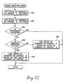
block 140, a test is made to determine if the link is a unidirectional link. If the link is a unidirectional link, the resolve direction is set to the direction of the link atblock 142 and the program shifts to block 122 (FIGURE 10). If not, a determination is made (block 144) as to whether source A of the link is set and source B is not set. If source A is set and source B is not set, the resolve direction is set to A→B atblock 146, and the program shifts to block 122. Otherwise, a test is made to determine (block 148) whether source B is set and source A is not set. If source B is set and source A is not, the resolve direction is set to B→A atblock 150 and the program shifts to block 122. Otherwise, atblock 152, a test is made to determine whether one graphical element has a lower element distance than the other. If the determination is yes, the resolve direction is set atblock 154 so that it points from the graphical element with a lower element distance to the graphical element with a higher element distance (i.e., such that the graphical element furthest from the source node will be changed). Then, the program shifts to block 122. If both graphical elements have the same distance, a random resolve direction is selected atblock 156 and the program shifts to block 122. - FIGURE 12 is a flow diagram illustrating the Resolve_Link part of the Solve method subroutine shown in FIGURE 10. Resolve_Link changes either the value of the graphical object at source A of a link or at source B of a link so that the constraint specified by the link will be satisfied. The Solve method subroutine provides a resolve direction for each link as a parameter to Resolve_Link indicating which of the two graphical elements should be changed to satisfy the constraint imposed by the link. At
block 180, a Get_Value procedure retrieves the value of the graphical element at source A of the link. Atblock 182, Get_Value retrieves the value of the graphical element at source B of the link. Atblock 184, a test is made to determine if the constraint imposed by the link is satisfied by comparing the value of the graphical element at source A to the value of the graphical element at source B. If the constraint is satisfied, Resolve_Link is done and the program shifts to block 132 (FIGURE 10). If the constraint is not satisfied, the Resolve_Link proceeds to block 186. - At
block 186, a test is made to determine if the resolve direction is A→B. If the resolve direction is not A→B (i.e., the direction is B→A), atblock 188 the value of the graphical element at source A is set based on the value of the graphical element at source B in light of the constraint and the program ends. If the resolve direction is A→B, atblock 190 the value of the graphical element at source B is set based on the value of the graphical element at source A. After the resolve direction has been set, the program shifts to block 132 of the Solve method subroutine (FIGURE 10). - FIGURE 13 is a flow diagram illustrating a subroutine suitable for carrying out the Set_Dirty method of the graphical applications program. At
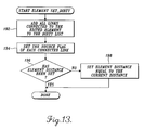
block 192, each link that is coupled to the edited graphical element is added to the dirty list. Atblock 194, a source flag (i.e., A or B) associated with each connected link is set. At block 196 a test is made to determine if the element distance has been set. If the element distance has been set, the subroutine ends. This indicates that the graphical element connected to the link has already been assigned an element distance from the source node. If the element distance has not been set, the element distance is set equal to the current distance (block 198) and the subroutine ends. - FIGURE 14 illustrates a subroutine for resolving links that are attached to a distribution frame. This method is called whenever a distribution frame is created or modified. The method may be called from a global routine or from the Solve method subroutine, although this call is not shown in FIGURE 10. At
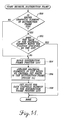
block 200, a test is made to determine if an edited graphical element, for example, a newly added element or one that has been modified, is in the distribution frame element position list (frame position list). If the edited graphical element is not in the frame position list, the program jumps ahead to block 204. If the graphical element is in the frame position list, a test is made to determine (block 202) whether the value of the graphical element matches the position specified by the list. If the value and the position match, the subroutine ends. If there is not a match, the program proceeds to block 204. - At
block 204, a new frame position list is built by including each graphical element that is attached to the distribution frame. Next, atblock 206, the graphical elements are arranged based on criteria set forth in the distribution frame. Then, atblock 208, the values for each graphical element in the position list are set. Thus, each graphical element is placed in the appropriate location and has the size specified by the position list. Then, the subroutine ends. - FIGURE 14 is explained further in FIGURE 15. The concepts underlining arrangement of graphical elements within the distribution frame stem from the vertical and horizontal alignment and distribution criteria generally set forth in FIGURE 7 and described in TABLE 1. A general rule of arrangement is that the graphical element positions are chosen such that the movement of elements from their original locations is minimized.
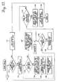
- FIGURE 15 is a hierarchical block diagram addressing the arrangement of graphical elements on the horizontal axis. As will be appreciated, vertical element arrangement is similar. Extending downwardly from an arrange
block 210 are the distribution and alignment options atblocks block 216, and (b) distribution via graphical element edges, as indicated byblock 218. Distribution by size refers to evenly spacing the graphical elements regardless of individual element sizes The edges of graphical elements atblock 218 may be aligned according to three attributes, the left edges of the elements (block 220), the centers of the elements (block 222), and the right edges of the elements (block 226). - In addition to size and edge distribution arrangements, resizing options may also be selected to affect the graphical element arrangement. These are indicated at
block 228, and include a no resizing option atblock 230, a resize frame to fit elements option atblock 232, and resize elements to fit frame option atblock 234. If the user chooses to resize the frame to fit the elements enclosed in the frame, the width of the distribution frame will equal the sum of the element widths plus the desired space between each graphical element, as indicated atblock 236. If the resize elements to fit the frame option is chosen, the width of each element will be set equal to (the width of the frame divided by the number of elements) minus the space between each element. This is indicated atblock 238. The left, center and right branches of the edges ofblock 218 include the same resizing options described in blocks 228-238. - The
align block 214 also includes left, center and right alignment options atblocks blocks 246. These also include no resizing atblock 248, resize frame to fit elements atblock 250, and resize elements to fit frame atblock 252. If the frame is resized to fit the elements, the frame width is set equal to the width of the widest element, as indicated atblock 254. If the elements are being resized to fit the frame, the width of all of the objects is set equal to the width of the frame as indicated atblock 256. Thus, FIGURE 15 indicates in general terms the flow that may be used to arrange graphical elements based on criteria set forth in the ADF dialog tool. - FIGURE 16 is a block diagram of a set of three
graphical elements Graphical element 270 is linked tographical element 272 by a link L1 having a source A atelement 270 and a source B atelement 272. The link L1 is assumed to be bidirectional, as is indicated byreference numeral 278. A unidirectional link L2 couples thegraphical element 272 with thegraphical element 274. The direction of the link is toward thegraphical element 272, as is indicated byarrow 282. A third link L3 also couples thegraphical elements graphical element 272 and source B coupled tographical element 274. - This example references the flow diagrams illustrated in FIGURES 10-13. As was stated above, the graphical applications program includes a global routine that is continually checking for and able to identify modifications made to graphical elements in a document. In that regard, in FIGURE 16 it is assumed that the
graphical element 270 has been edited. The global routine performs the following steps: (1) perceives that the user has modified a graphical element and thus makes a call to element Set_Dirty (FIGURE 13), (2) makes a call to the Solve method subroutine within the constraint engine, and (3) updates the screen, thereby displaying the modifications made to the document. Throughout this example, a snapshot will be taken immediately afterblock 126 of the Solve method (FIGURE 10) to: (a) indicate the resolve direction of any links that are in one of the four priority lists, (b) indicate which priority list they are in, and (c) indicate the value of the variable current distance. These snapshots are illustrated in TABLE 3.TABLE 3 Snapshots of Solve Method Resolve Direction Priority List Current Distance Snapshot 1 A→B (Link L1) 2 (Link L1) 1 Snapshot 2 B→A (Link L2) 1 (Link L2) 2 A→B (Link L3) 2 (Link L3) Snapshot 3 B→A (Link L1) 4 (Link L1) 3 A→B (Link L3) 2 (Link L3) Snapshot 4 B→A (Link L1) 4 (Link L1) 4 A→B (Link L2) 1 (Link L2) Snapshot 5 B→A (Link L1) 4 (Link L1) 5 - Upon calling Element Set_Dirty, link L1 is added to the dirty list and the source A of link L1 is set in
blocks block 114, link L1 is added to Priority List 2 and the resolve direction for link L1 is set to A→B atblock 120. This yields the data found insnapshot 1 of TABLE 3. - At
block 128, Resolve_Link is called and thegraphical element 270 is compared to thegraphical element 272 to see if the constraint of link L1 is satisfied. Assuming that the constraint of link L1 is not satisfied, Set_Value is called atblock 190 wherein thegraphical element 272 will be set based upon the value ofgraphical element 270. Thereafter, the Set_Value method calls Element Set_Dirty where, atblock 192, link L2 and link L3 are added to the dirty list and the source flags that are coupled to graphical element 272 (A in both cases) are set. Control is then returned to Solve, which loops back to block 110. Atblock 114, the current distance is incremented to two. In the loop 116-122, link L2 is assigned toList 1 and set with a resolve direction B→A. Also in this loop, link L3 is added to List 2, and its resolve direction is set to A→B. Atblock 126, the current list is set equal toList 1. The snapshot 2 at TABLE 3 indicates the current status of the links present in the priority lists. - At
block 130, the Resolve_Link routine is called, where the constraints betweengraphical elements block 184. Assuming the constraint is not satisfied, the value of theelement 274 will be set equal to the value of theelement 272 atblock 188. The Set_Value method will again call Element Set_Dirty, which will add link L1 to the dirty list, becausegraphical element 272 was modified. Control returns to the Solve method where the current distance is incremented to three and link L1 is added to List 4. Further, at block 120 a resolve direction of B→A is set for link L1. Atblock 126, the current list is set equal to List 2 as it is the highest priority list that is not empty. The current state of the example is evidenced at snapshot 3 in TABLE 3. - At this point, the current list (List 2) is not empty, and Resolve_Link is called at
block 130. Atblock 184 of Resolve_Link, it is determined whether the constraint of link L3 is satisfied by comparing the value ofgraphical element 272 tographical element 274. Assuming that the constraint is not satisfied, the value ofgraphical element 274 is changed based on the value ofelement 272. Thereafter, element Set_Dirty is called and link L2 is added to the dirty list. Control is then returned to block 128 of the Solve method, which branches to block 110. The current distance is incremented to four atblock 114 and link L2 is added toList 1 in blocks 116-122. The current list is then set equal toList 1 atblock 126. The current status of the variables of interest is at snapshot 4 of TABLE 3. Resolve_Link is called atblock 130. - In the Resolve_Link routine, it is assumed for this example that the constraint is satisfied and control is returned to the Solve method. While there are no links in the dirty list at this point, link L1 is still in List 4, and thus the program continues to block 114 where the current distance is incremented to 5. Flow continues to block 126, where the current list is set equal to List 4. At this point, the snapshot5 indicates the current status of the resolve direction, priority lists, and current distance. The program continues to block 130, where Resolve_Link is called. At
block 184, the value ofgraphical element 272 is compared to the value ofgraphical element 270. At this point, it is assumed that the constraint of link L1 is satisfied, and control returns to the Solve method. The Solve method loops back to block 110, wherein the dirty and priority lists are empty. Thus, the program continues to block 112 where the current distance is set equal to zero and the program terminates. - The constraint engine is a very efficient means for solving constraints. Constraint solvers used in other arts typically have a planning stage that preplans the ordering of constraints by looking at the constraints specified by different values. It is thus the preplanning stage that develops an evaluation order for the constraints. In contrast, the constraint engine of the invention essentially "plans" as it solves constraints, through the use of the priority lists, element distance values and link directions.
- The constraint engine is also advantageous in that it provides incremental and partial solutions to constraint problems. Incremental solutions can be provided in that the way the Dirty_List is implemented, the Solve method can be stopped at any time for a partial solution to a constraint problem. There is no overhead in setup or cleanup time for starting or stopping the Solve method. Partial solutions are provided in that if the Solve method takes too long to find a solution or there is no solution, a partial solution is presented to the user. Further advantages of the constraint engine are that graphical element internals are hidden from the constraints. This is because the only access to the internals of graphical elements is through the Get_Value and Set_Value methods. Finally, the constraint internals are hidden in that the only access by the Solve method to the constraints is through the Resolve_Link method. This makes the implementation of constraints very flexible.
- While a preferred embodiment of the invention has been illustrated and described, it will be appreciated that various changes can be made therein without departing from the spirit and scope of the invention.
Claims (76)
- A method of specifying the spatial relationships between graphical elements comprising the steps of:(a) creating a distribution frame;(b) placing a set of graphical elements within the distribution frame; and(c) creating alignment and distribution criteria that determine spatial relationships between the graphical elements placed within the distribution frame.
- The method of Claim 1 wherein the step of creating alignment and distribution criteria includes the substep of creating spatial relationships for selected ones of the graphical elements along at least one vertical axis.
- The method of Claim 1 wherein the step of creating alignment and distribution criteria includes the substep of creating spatial relationships for selected ones of the graphical elements along at least one horizontal axis.
- The method of Claim 1 wherein the step of creating alignment and distribution criteria includes the substep of creating spatial relationships for selected ones of the graphical elements along at least one horizontal axis.
- The method of Claim 1 wherein the step of creating alignment and distribution criteria includes the substep of sizing the distribution frame to fit the set of graphical elements.
- The method of Claim 5 wherein the step of creating alignment and distribution criteria includes the substep of creating spatial relationships for selected ones of the graphical elements along at least one vertical axis.
- The method of Claim 6 wherein the step of creating alignment and distribution criteria includes the substep of creating spatial relationships for selected ones of the graphical elements along at least one horizontal axis.
- The method of Claim 5 wherein the step of creating alignment and distribution criteria includes the substep of creating spatial relationships for selected ones of the graphical elements along at least one horizontal axis.
- The method of Claim 1 wherein the step of creating alignment and distribution criteria includes the substeps of sizing the set of graphical elements to fit the distribution frame.
- The method of Claim 9 wherein the step of creating alignment and distribution criteria includes the substep of creating spatial relationships for selected ones of the graphical elements along at least one vertical axis.
- The method of Claim 10 wherein the step of creating alignment and distribution criteria includes the substep of creating spatial relationships for selected ones of the graphical elements along at least one horizontal axis.
- The method of Claim 9 wherein the step of creating alignment and distribution criteria includes the substep of creating spatial relationships for selected ones of the graphical elements along at least one horizontal axis.
- The method of Claim 1 wherein the step of creating alignment and distribution criteria includes the substep of locking the order of the graphical elements that form the set of graphical elements such that the graphical elements cannot be rearranged within the distribution frame.
- The method of Claim 13 wherein the step of creating alignment and distribution criteria includes the substep of creating spatial relationships for selected ones of the graphical elements along at least one vertical axis.
- The method of Claim 14 wherein the step of creating alignment and distribution criteria includes the substep of creating spatial relationships for selected ones of the graphical elements along at least one horizontal axis.
- The method of Claim 13 wherein the step of creating alignment and distribution criteria includes the substep of creating spatial relationships for selected ones of the graphical elements along at least one horizontal axis.
- The method of Claim 13 wherein the step of creating alignment and distribution criteria includes the substep of sizing the distribution frame to fit the set of graphical elements.
- The method of Claim 17 wherein the step of creating alignment and distribution criteria includes the substep of creating spatial relationships for selected ones of the graphical elements along at least one vertical axis.
- The method of Claim 18 wherein the step of creating alignment and distribution criteria includes the substep of creating spatial relationships for selected ones of the graphical elements along at least one horizontal axis.
- The method of Claim 17 wherein the step of creating alignment and distribution criteria includes the substep of creating spatial relationships for selected ones of the graphical elements along at least one horizontal axis.
- The method of Claim 13 wherein the step of creating alignment and distribution criteria includes the substeps of sizing the set of graphical elements to fit the distribution frame.
- The method of Claim 21 wherein the step of creating alignment and distribution criteria includes the substep of creating spatial relationships for selected ones of the graphical elements along at least one vertical axis.
- The method of Claim 22 wherein the step of creating alignment and distribution criteria includes the substep of creating spatial relationships for selected ones of the graphical elements along at least one horizontal axis.
- The method of Claim 21 wherein the step of creating alignment and distribution criteria includes the substep of creating spatial relationships for selected ones of the graphical elements along at least one horizontal axis.
- A method of specifying the spatial relationships between graphical elements comprising the steps of:(a) creating a set of graphical elements;(b) surrounding said set of graphical elements with a distribution frame; and(c) creating alignment and distribution criteria that determine spatial relationships between the graphical elements surrounded by said distribution frame.
- The method of Claim 25 wherein the step of creating alignment and distribution criteria includes the substep of creating spatial relationships for selected ones of the graphical elements along at least one vertical axis.
- The method of Claim 26 wherein the step of creating alignment and distribution criteria includes the substep of creating spatial relationships for selected ones of the graphical elements along at least one horizontal axis.
- The method of Claim 25 wherein the step of creating alignment and distribution criteria includes the substep of creating spatial relationships for selected ones of the graphical elements along at least one horizontal axis.
- The method of Claim 25 wherein the step of creating alignment and distribution criteria includes the substep of sizing the distribution frame to fit the set of graphical elements.
- The method of Claim 29 wherein the step of creating alignment and distribution criteria includes the substep of creating spatial relationships for selected ones of the graphical elements along at least one vertical axis.
- The method of Claim 30 wherein the step of creating alignment and distribution criteria includes the substep of creating spatial relationships for selected ones of the graphical elements along at least one horizontal axis.
- The method of Claim 29 wherein the step of creating alignment and distribution criteria includes the substep of creating spatial relationships for selected ones of the graphical elements along at least one horizontal axis.
- The method of Claim 25 wherein the step of creating alignment and distribution criteria includes the substeps of sizing the set of graphical elements to fit the distribution frame.
- The method of Claim 33 wherein the step of creating alignment and distribution criteria includes the substep of creating spatial relationships for selected ones of the graphical elements along at least one vertical axis.
- The method of Claim 34 wherein the step of creating alignment and distribution criteria includes the substep of creating spatial relationships for selected ones of the graphical elements along at least one horizontal axis.
- The method of Claim 33 wherein the step of creating alignment and distribution criteria includes the substep of creating spatial relationships for selected ones of the graphical elements along at least one horizontal axis.
- The method of Claim 25 wherein the step of creating alignment and distribution criteria includes the substep of locking the order of the graphical elements that form the set of graphical elements such that the graphical elements cannot be rearranged within the distribution frame.
- The method of Claim 37 wherein the step of creating alignment and distribution criteria includes the substep of creating spatial relationships for selected ones of the graphical elements along at least one vertical axis.
- The method of Claim 38 wherein the step of creating alignment and distribution criteria includes the substep of creating spatial relationships for selected ones of the graphical elements along at least one horizontal axis.
- The method of Claim 37 wherein the step of creating alignment and distribution criteria includes the substep of creating spatial relationships for selected ones of the graphical elements along at least one horizontal axis.
- The method of Claim 37 wherein the step of creating alignment and distribution criteria includes the substep of sizing the distribution frame to fit the set of graphical elements.
- The method of Claim 41 wherein the step of creating alignment and distribution criteria includes the substep of creating spatial relationships for selected ones of the graphical elements along at least one vertical axis.
- The method of Claim 42 wherein the step of creating alignment and distribution criteria includes the substep of creating spatial relationships for selected ones of the graphical elements along at least one horizontal axis.
- The method of Claim 37 wherein the step of creating alignment and distribution criteria includes the substep of creating spatial relationships for selected ones of the graphical elements along at least one horizontal axis.
- The method of Claim 37 wherein the step of creating alignment and distribution criteria includes the substeps of sizing the set of graphical elements to fit the distribution frame.
- The method of Claim 45 wherein the step of creating alignment and distribution criteria includes the substep of creating spatial relationships for selected ones of the graphical elements along at least one vertical axis.
- The method of Claim 46 wherein the step of creating alignment and distribution criteria includes the substep of creating spatial relationships for selected ones of the graphical elements along at least one horizontal axis.
- The method of Claim 45 wherein the step of creating alignment and distribution criteria includes the substep of creating spatial relationships for selected ones of the graphical elements along at least one horizontal axis.
- A method of specifying the spatial relationships between graphical elements comprising the steps of:(a) creating a set of graphical elements;(b) creating alignment and distribution criteria that determine spatial relationships between said graphical elements; and(c) surrounding said set of graphical elements with a distribution frame.
- The method of Claim 49 wherein the step of creating alignment and distribution criteria includes the substep of creating spatial relationships for selected ones of the graphical elements along at least one vertical axis.
- The method of Claim 50 wherein the step of creating alignment and distribution criteria includes the substep of creating spatial relationships for selected ones of the graphical elements along at least one horizontal axis.
- The method of Claim 49 wherein the step of creating alignment and distribution criteria includes the substep of creating spatial relationships for selected ones of the graphical elements along at least one horizontal axis.
- The method of Claim 49 wherein the step of creating alignment and distribution criteria includes the substep of sizing the distribution frame to fit the set of graphical elements.
- The method of Claim 53 wherein the step of creating alignment and distribution criteria includes the substep of creating spatial relationships for selected ones of the graphical elements along at least one vertical axis.
- The method of Claim 54 wherein the step of creating alignment and distribution criteria includes the substep of creating spatial relationships for selected ones of the graphical elements along at least one horizontal axis.
- The method of Claim 53 wherein the step of creating alignment and distribution criteria includes the substep of creating spatial relationships for selected ones of the graphical elements along at least one horizontal axis.
- The method of Claim 49 wherein the step of creating alignment and distribution criteria includes the substeps of sizing the set of graphical elements to fit the distribution frame.
- The method of Claim 57 wherein the step of creating alignment and distribution criteria includes the substep of creating spatial relationships for selected ones of the graphical elements along at least one vertical axis.
- The method of Claim 58 wherein the step of creating alignment and distribution criteria includes the substep of creating spatial relationships for selected ones of the graphical elements along at least one horizontal axis.
- The method of Claim 57 wherein the step of creating alignment and distribution criteria includes the substep of creating spatial relationships for selected ones of the graphical elements along at least one horizontal axis.
- The method of Claim 49 wherein the step of creating alignment and distribution criteria includes the substep of locking the order of the graphical elements that form the set of graphical elements such that the graphical elements cannot be rearranged within the distribution frame.
- The method of Claim 61 wherein the step of creating alignment and distribution criteria includes the substep of creating spatial relationships for selected ones of the graphical elements along at least one vertical axis.
- The method of Claim 62 wherein the step of creating alignment and distribution criteria includes the substep of creating spatial relationships for selected ones of the graphical elements along at least one horizontal axis.
- The method of Claim 61 wherein the step of creating alignment and distribution criteria includes the substep of creating spatial relationships for selected ones of the graphical elements along at least one horizontal axis.
- The method of Claim 61 wherein the step of creating alignment and distribution criteria includes the substep of sizing the distribution frame to fit the set of graphical elements.
- The method of Claim 65 wherein the step of creating alignment and distribution criteria includes the substep of creating spatial relationships for selected ones of the graphical elements along at least one vertical axis.
- The method of Claim 66 wherein the step of creating alignment and distribution criteria includes the substep of creating spatial relationships for selected ones of the graphical elements along at least one horizontal axis.
- The method of Claim 65 wherein the step of creating alignment and distribution criteria includes the substep of creating spatial relationships for selected ones of the graphical elements along at least one horizontal axis.
- The method of Claim 61 wherein the step of creating alignment and distribution criteria includes the substeps of sizing the set of graphical elements to fit the distribution frame.
- The method of Claim 69 wherein the step of creating alignment and distribution criteria includes the substep of creating spatial relationships for selected ones of the graphical elements along at least one vertical axis.
- The method of Claim 70 wherein the step of creating alignment and distribution criteria includes the substep of creating spatial relationships for selected ones of the graphical elements along at least one horizontal axis.
- The method of Claim 69 wherein the step of creating alignment and distribution criteria includes the substep of creating spatial relationships for selected ones of the graphical elements along at least one horizontal axis.
- A method of solving constraints between pairs of linked graphical elements after the graphical elements have been edited comprising the steps of:(a) creating a dirty list of links whose constraints are not currently satisfied; and(b) repetitively resolving the constraints associated with the links on the dirty list by changing the attributes of one of the graphical elements of the pair of linked graphical elements associated with the link whose constraint is being resolved.
- A method of maintaining constraints between graphical elements that have been edited comprising the steps of:(a) creating a link between each pair of graphical elements that are to be coupled by a constraint;(b) determining if the constraint associated with each pair of linked graphical elements is satisfied;(c) creating a dirty list of links whose constraints are not currently satisfied; and(d) resolving the constraints associated with the links on the dirty list by changing the attributes of one of the graphical elements attached to the link in accordance with the constraint.
- A method of solving the constraints between pairs of linked graphical elements after the graphical elements have been edited comprising the steps of:(a) creating a dirty list of links whose constraints are not currently satisfied;(b) prioritizing the dirty list based on a predetermined criteria;(c) resolving the constraint associated with the link on the prioritized dirty list having the highest priority by changing the attributes of one of the graphical elements attached to the link; and(d) repeating step (c) until the constraints associated with all of the links on the prioritized dirty list have been resolved.
- The method claimed in Claim 75 wherein the step of prioritizing the dirty list comprises the substeps of creating a set of more than one priority list and assigning each link on the dirty list to one of the priority lists.
Applications Claiming Priority (2)
| Application Number | Priority Date | Filing Date | Title |
|---|---|---|---|
| US07/904,059 US5437008A (en) | 1992-06-23 | 1992-06-23 | Method of establishing constraints and links in a distribution frame between graphical elements and resolving the constaints |
| US904059 | 1997-07-31 |
Publications (3)
| Publication Number | Publication Date |
|---|---|
| EP0576178A2 true EP0576178A2 (en) | 1993-12-29 |
| EP0576178A3 EP0576178A3 (en) | 1995-01-25 |
| EP0576178B1 EP0576178B1 (en) | 2003-03-05 |
Family
ID=25418476
Family Applications (1)
| Application Number | Title | Priority Date | Filing Date |
|---|---|---|---|
| EP93304530A Expired - Lifetime EP0576178B1 (en) | 1992-06-23 | 1993-06-10 | Method of maintaining relationships between elements |
Country Status (6)
| Country | Link |
|---|---|
| US (3) | US5437008A (en) |
| EP (1) | EP0576178B1 (en) |
| JP (2) | JPH0696180A (en) |
| AU (1) | AU4013193A (en) |
| CA (1) | CA2098163A1 (en) |
| DE (1) | DE69332731T2 (en) |
Cited By (10)
| Publication number | Priority date | Publication date | Assignee | Title |
|---|---|---|---|---|
| EP0631251A2 (en) * | 1993-06-21 | 1994-12-28 | Canon Kabushiki Kaisha | Graphics correcting method and system employing same |
| EP0647921A2 (en) * | 1993-10-08 | 1995-04-12 | Xerox Corporation | Structured image(si)format for describing complex color raster images |
| EP0690415A3 (en) * | 1994-06-30 | 1996-12-04 | Xerox Corp | Editing scanned document images using simple interpretations |
| NL1000701C2 (en) * | 1995-06-30 | 1996-12-31 | Oce Nederland Bv | Device and method for extracting articles from a document. |
| EP0848351A2 (en) * | 1996-12-13 | 1998-06-17 | Adobe Systems, Inc. | Method and apparatus for automatically modifying document layout |
| WO2000063844A1 (en) * | 1999-04-20 | 2000-10-26 | Koninklijke Philips Electronics N.V. | A method and apparatus for interactively constructing relational geometric objects |
| WO2009036031A1 (en) * | 2007-09-11 | 2009-03-19 | Vistaprint Technologies Limited | Caricature tool |
| WO2021097141A1 (en) * | 2019-11-13 | 2021-05-20 | Figma, Inc. | System and method for implementing design system to provide preview of constraint conflicts |
| US11106339B2 (en) * | 2017-09-19 | 2021-08-31 | Adobe Inc. | Designing and resizing graphical user interfaces |
| US11733973B2 (en) | 2020-09-16 | 2023-08-22 | Figma, Inc. | Interactive graphic design system to enable creation and use of variant component sets for interactive objects |
Families Citing this family (96)
| Publication number | Priority date | Publication date | Assignee | Title |
|---|---|---|---|---|
| US5519606A (en) * | 1992-01-21 | 1996-05-21 | Starfish Software, Inc. | System and methods for appointment reconciliation |
| US5437008A (en) * | 1992-06-23 | 1995-07-25 | Adobe Systems Incorporated | Method of establishing constraints and links in a distribution frame between graphical elements and resolving the constaints |
| US5951300A (en) * | 1997-03-10 | 1999-09-14 | Health Hero Network | Online system and method for providing composite entertainment and health information |
| ES2090834T3 (en) * | 1993-02-08 | 1996-10-16 | Patrick Megard | SYSTEM OF CONCEPTION AND MANUFACTURING ASSISTED BY COMPUTER. |
| US5990888A (en) * | 1994-03-22 | 1999-11-23 | International Business Machines Corporation | Method and system for manipulating graphical objects |
| US5546520A (en) * | 1994-09-30 | 1996-08-13 | International Business Machines Corporation | Method, system, and memory for reshaping the frame edges of a window around information displayed in the window |
| US5682468A (en) | 1995-01-23 | 1997-10-28 | Intergraph Corporation | OLE for design and modeling |
| US5671378A (en) * | 1995-03-31 | 1997-09-23 | International Business Machines Corporation | Method and system for sizing of graphical user interface objects for localization |
| US5692184A (en) * | 1995-05-09 | 1997-11-25 | Intergraph Corporation | Object relationship management system |
| US5771342A (en) * | 1995-06-05 | 1998-06-23 | Saltire Software | Method and apparatus for dynamically displaying consistently dimensioned two-dimensional drawings |
| JP3109421B2 (en) * | 1995-09-08 | 2000-11-13 | 富士ゼロックス株式会社 | Chart processing equipment |
| US6081277A (en) * | 1995-09-28 | 2000-06-27 | Sony Corporation | Apparatus and method for controlling image display |
| TW331612B (en) * | 1996-03-05 | 1998-05-11 | Soft Future Design Kk | Data processing apparatus and register address translation method. |
| US5751283A (en) * | 1996-07-17 | 1998-05-12 | Microsoft Corporation | Resizing a window and an object on a display screen |
| US6061067A (en) * | 1996-08-02 | 2000-05-09 | Autodesk, Inc. | Applying modifiers to objects based on the types of the objects |
| US6215502B1 (en) * | 1996-10-28 | 2001-04-10 | Cks Partners | Method and apparatus for automatically reconfiguring graphical objects relative to new graphical layouts |
| US6157380A (en) * | 1996-11-05 | 2000-12-05 | International Business Machines Corporation | Generic mechanism to create opendoc parts from workplace shell objects |
| US6304272B1 (en) * | 1996-12-10 | 2001-10-16 | Micrografx, Inc. | Graphics system and method having objects conformed to a template |
| US5999186A (en) * | 1997-05-23 | 1999-12-07 | 3-Design L.L.C. | Reference based parametric dimensioning method and system |
| US6236407B1 (en) * | 1997-07-10 | 2001-05-22 | Bruce Leban | Method for creating graphical images |
| US6035305A (en) * | 1997-08-29 | 2000-03-07 | The Boeing Company | Computer-based method of structuring product configuration information and configuring a product |
| US6774899B1 (en) * | 1997-09-18 | 2004-08-10 | Mitsubishi Electric Research Laboratories, Inc. | Drawing graphs using user selectable visual oragnization features and/or other user controlled constraints |
| JPH11154240A (en) | 1997-11-20 | 1999-06-08 | Nintendo Co Ltd | Image producing device to produce image by using fetched image |
| US6435969B1 (en) | 1998-11-03 | 2002-08-20 | Nintendo Co., Ltd. | Portable game machine having image capture, manipulation and incorporation |
| US6295056B1 (en) * | 1998-12-03 | 2001-09-25 | International Business Machines | Modulating the dimensions of environmentally related and proportionally sized displayed objects to conform selected object dimensions to limitations of a defined display space |
| JP3556501B2 (en) * | 1999-01-14 | 2004-08-18 | 株式会社山武 | Drawing creation equipment |
| US6469715B1 (en) | 1999-03-19 | 2002-10-22 | Corel Inc. | System and method for controlling the operation of a graphical object using a project |
| US6480203B1 (en) | 1999-03-19 | 2002-11-12 | Corel Inc. | System and method for processing an event of a graphical object |
| US6549199B1 (en) | 1999-03-19 | 2003-04-15 | Corel Inc. | System and method for adjusting a graphical object |
| US6469716B1 (en) | 1999-03-19 | 2002-10-22 | Corel Inc. | System and method for processing data for a graphical object |
| US7233326B1 (en) * | 1999-04-29 | 2007-06-19 | Autodesk, Inc. | Three dimensional modeling and animation system using master objects and modifiers |
| US6369829B1 (en) * | 1999-09-02 | 2002-04-09 | Autodesk, Inc. | Constructive systems for objects in a computer-implemented graphics system |
| US6380951B1 (en) | 1999-10-01 | 2002-04-30 | Global Graphics Software Limited | Prepress workflow method and program |
| US6483524B1 (en) | 1999-10-01 | 2002-11-19 | Global Graphics Software Limited | Prepress workflow method using raster image processor |
| US6624908B1 (en) | 1999-10-01 | 2003-09-23 | Global Graphics Software Limited | Method for arranging a prepress workflow |
| US6931591B1 (en) * | 1999-10-15 | 2005-08-16 | Saepio Technologies, Inc. | Publishing layout wizard |
| US8132097B2 (en) * | 1999-10-15 | 2012-03-06 | Saepio Technologies, Inc. | Computer-implemented system for creating a publication and method thereof |
| US6826727B1 (en) | 1999-11-24 | 2004-11-30 | Bitstream Inc. | Apparatus, methods, programming for automatically laying out documents |
| US7266762B1 (en) | 2000-03-10 | 2007-09-04 | International Business Machines Corporation | Method and system for distributed autonomous maintenance of bidirectional hyperlink metadata on the web and similar hypermedia repository |
| US7771482B1 (en) * | 2000-05-09 | 2010-08-10 | Ben-Zion Karmon | Method for tissue expansion and regeneration using bioresorbable inflatable devices |
| US7076412B1 (en) * | 2000-05-12 | 2006-07-11 | Autodesk, Inc. | Method and apparatus for storing and selectively retrieving dimensions of geometry pieces of a mechanical design |
| US6894686B2 (en) | 2000-05-16 | 2005-05-17 | Nintendo Co., Ltd. | System and method for automatically editing captured images for inclusion into 3D video game play |
| JP2002042126A (en) | 2000-05-19 | 2002-02-08 | Sony Computer Entertainment Inc | Storage medium storing display control program, entertainment device, and display control program |
| US6686935B1 (en) * | 2000-05-24 | 2004-02-03 | International Business Machines Corporation | Method and apparatus for object kerning |
| US7093196B1 (en) * | 2000-06-10 | 2006-08-15 | Oracle International Corporation | Method and apparatus for aligning items relatively within an electronic document |
| US6993708B1 (en) * | 2000-07-27 | 2006-01-31 | Robert B Gillig | System for automated generation and assembly of specifications documents in CADD environments |
| US6919890B2 (en) * | 2000-09-28 | 2005-07-19 | Curl Corporation | Grid and table layout using elastics |
| US20020111969A1 (en) * | 2000-09-28 | 2002-08-15 | Halstead Robert H. | System and method for processing graphical objects for layout using an elastic difference operation |
| US7181699B2 (en) * | 2001-06-13 | 2007-02-20 | Microsoft Corporation | Dynamic resizing of dialogs |
| US6950993B2 (en) * | 2001-08-02 | 2005-09-27 | Microsoft Corporation | System and method for automatic and dynamic layout of resizable dialog type windows |
| US7068271B2 (en) * | 2001-09-05 | 2006-06-27 | Autodesk, Inc. | Assembly patterns by feature association |
| US6907573B2 (en) | 2001-09-28 | 2005-06-14 | Autodesk, Inc. | Intelligent constraint definitions for assembly part mating |
| US6928618B2 (en) * | 2001-10-23 | 2005-08-09 | Autodesk, Inc. | Intelligent drag of assembly components |
| US20030163786A1 (en) * | 2002-02-25 | 2003-08-28 | Harold Shields | Image presentation system |
| US7339597B1 (en) | 2002-06-21 | 2008-03-04 | Adobe Systems Incorporated | Creating and manipulating related vector objects in an image |
| US7027071B2 (en) * | 2002-07-02 | 2006-04-11 | Hewlett-Packard Development Company, L.P. | Selecting elements from an electronic document |
| US20080143725A1 (en) | 2004-02-09 | 2008-06-19 | Smart Technologies Inc. | Connected and overlapped shapes enhancements |
| US20040221265A1 (en) * | 2003-02-07 | 2004-11-04 | Smart Technologies Inc. | Connected and overlapped shapes enhancements |
| US20040207607A1 (en) * | 2003-04-15 | 2004-10-21 | Will Specks | Operating element having an integrated display element, and a method for command output using an operating element |
| US7360157B1 (en) | 2003-09-19 | 2008-04-15 | Microsoft Corporation | Aligning content in an electronic document |
| DE10352341A1 (en) * | 2003-11-06 | 2005-11-03 | Mediacare Gmbh & Co. Kg | Method for changing the dimensions of an electronically stored image |
| JP4110105B2 (en) * | 2004-01-30 | 2008-07-02 | キヤノン株式会社 | Document processing apparatus, document processing method, and document processing program |
| JP4250540B2 (en) * | 2004-01-30 | 2009-04-08 | キヤノン株式会社 | Layout adjustment method and apparatus, and layout adjustment program |
| JP4165888B2 (en) * | 2004-01-30 | 2008-10-15 | キヤノン株式会社 | Layout control method, layout control apparatus, and layout control program |
| JP4241410B2 (en) * | 2004-01-30 | 2009-03-18 | キヤノン株式会社 | Layout adjustment method and apparatus, and layout adjustment program |
| US8661332B2 (en) | 2004-04-30 | 2014-02-25 | Microsoft Corporation | Method and apparatus for document processing |
| US7383500B2 (en) | 2004-04-30 | 2008-06-03 | Microsoft Corporation | Methods and systems for building packages that contain pre-paginated documents |
| US7359902B2 (en) * | 2004-04-30 | 2008-04-15 | Microsoft Corporation | Method and apparatus for maintaining relationships between parts in a package |
| US7519899B2 (en) * | 2004-05-03 | 2009-04-14 | Microsoft Corporation | Planar mapping of graphical elements |
| US7580948B2 (en) | 2004-05-03 | 2009-08-25 | Microsoft Corporation | Spooling strategies using structured job information |
| US20050246384A1 (en) * | 2004-05-03 | 2005-11-03 | Microsoft Corporation | Systems and methods for passing data between filters |
| US8363232B2 (en) | 2004-05-03 | 2013-01-29 | Microsoft Corporation | Strategies for simultaneous peripheral operations on-line using hierarchically structured job information |
| US7755786B2 (en) | 2004-05-03 | 2010-07-13 | Microsoft Corporation | Systems and methods for support of various processing capabilities |
| US7607141B2 (en) * | 2004-05-03 | 2009-10-20 | Microsoft Corporation | Systems and methods for support of various processing capabilities |
| US8243317B2 (en) | 2004-05-03 | 2012-08-14 | Microsoft Corporation | Hierarchical arrangement for spooling job data |
| US7634775B2 (en) | 2004-05-03 | 2009-12-15 | Microsoft Corporation | Sharing of downloaded resources |
| JP4095592B2 (en) * | 2004-08-06 | 2008-06-04 | キヤノン株式会社 | Information processing apparatus, information processing method, and program |
| JP4047308B2 (en) * | 2004-08-06 | 2008-02-13 | キヤノン株式会社 | Layout processing method, information processing apparatus, and computer program |
| US7889361B2 (en) * | 2004-10-15 | 2011-02-15 | Electronics For Imaging, Inc. | Methods and apparatus for adaptive imposition templates |
| US7584111B2 (en) * | 2004-11-19 | 2009-09-01 | Microsoft Corporation | Time polynomial Arrow-Debreu market equilibrium |
| JP4393444B2 (en) * | 2005-11-02 | 2010-01-06 | キヤノン株式会社 | Information processing method and apparatus |
| US20070157160A1 (en) * | 2005-12-30 | 2007-07-05 | Udo Arend | Auto-zoomable snippets in multiple snippet windows |
| US8694953B2 (en) * | 2006-08-14 | 2014-04-08 | Payman Khodabandehloo | Tool and methodology for enterprise software applications |
| JP2008129729A (en) * | 2006-11-17 | 2008-06-05 | Olympus Corp | Information processor and control program |
| US8015581B2 (en) | 2007-01-05 | 2011-09-06 | Verizon Patent And Licensing Inc. | Resource data configuration for media content access systems and methods |
| US8345043B2 (en) * | 2007-04-13 | 2013-01-01 | Autodesk, Inc. | Solving networks of geometric constraints |
| US7853887B2 (en) | 2007-06-26 | 2010-12-14 | Adobe Systems Incorporated | Detection and preview of graphical elements within a graphic |
| US9324168B2 (en) * | 2008-01-31 | 2016-04-26 | Microsoft Technology Licensing, Llc | Constraint-based correction of shape positions in a diagram |
| KR101232623B1 (en) * | 2010-12-07 | 2013-02-13 | 삼성메디슨 주식회사 | Method for Realizing Editing Function of User Menu |
| JP5673264B2 (en) * | 2011-03-18 | 2015-02-18 | 富士通株式会社 | Graphic drawing program and graphic drawing device |
| US10467714B2 (en) | 2013-03-15 | 2019-11-05 | Stevenson Systems, Inc. | Interactive building stacking plan user interface |
| US20150160838A1 (en) * | 2013-12-06 | 2015-06-11 | Takeshi SHIRABE | Method and apparatus for automatic graphic editing with map-dependent constraints |
| US9854258B2 (en) * | 2014-01-06 | 2017-12-26 | Disney Enterprises, Inc. | Video quality through compression-aware graphics layout |
| CA2964355A1 (en) * | 2014-10-22 | 2016-04-28 | Stevenson Systems, Inc. | Interactive building stacking plan user interface |
| USD829697S1 (en) * | 2014-12-30 | 2018-10-02 | Sony Corporation | Wireless communication device |
| US11966572B2 (en) | 2021-11-16 | 2024-04-23 | Figma, Inc. | Commenting feature for graphic design systems |
Family Cites Families (5)
| Publication number | Priority date | Publication date | Assignee | Title |
|---|---|---|---|---|
| US4974174A (en) * | 1987-08-24 | 1990-11-27 | Wang Laboratories, Inc. | Alignment method for positioning textual and graphic objects |
| US5123087A (en) * | 1990-04-27 | 1992-06-16 | Ashlar, Inc. | Geometric inference engine |
| US5371845A (en) * | 1990-04-27 | 1994-12-06 | Ashlar, Inc. | Technique for providing improved user feedback in an interactive drawing system |
| US5333254A (en) * | 1991-10-02 | 1994-07-26 | Xerox Corporation | Methods of centering nodes in a hierarchical display |
| US5437008A (en) * | 1992-06-23 | 1995-07-25 | Adobe Systems Incorporated | Method of establishing constraints and links in a distribution frame between graphical elements and resolving the constaints |
-
1992
- 1992-06-23 US US07/904,059 patent/US5437008A/en not_active Expired - Lifetime
-
1993
- 1993-06-08 AU AU40131/93A patent/AU4013193A/en not_active Abandoned
- 1993-06-10 CA CA002098163A patent/CA2098163A1/en not_active Abandoned
- 1993-06-10 DE DE69332731T patent/DE69332731T2/en not_active Expired - Lifetime
- 1993-06-10 EP EP93304530A patent/EP0576178B1/en not_active Expired - Lifetime
- 1993-06-23 JP JP5151798A patent/JPH0696180A/en active Pending
-
1995
- 1995-05-11 US US08/438,977 patent/US5577189A/en not_active Expired - Lifetime
-
1996
- 1996-08-20 US US08/700,038 patent/US5745122A/en not_active Expired - Lifetime
-
2002
- 2002-04-22 JP JP2002119372A patent/JP3634323B2/en not_active Expired - Lifetime
Non-Patent Citations (3)
| Title |
|---|
| COMPUTERS & GRAPHICS, vol.15, no.1, 1991, UK pages 57 - 66, XP179596 COSAR ET AL. 'a text, image and graphics editor' * |
| SIGPC NOTES. ACM CONFERENCE ON PERSONAL AND SMALL COMPUTERS., vol.6, no.2, 7 December 1983, USA pages 45 - 53 JOLOBOFF 'an interactive graphics editor for document preparation' * |
| SYTEMS AND COMPUTERS IN JAPAN, vol.22, no.14, 1991, USA pages 14 - 25, XP266847 MATSUURA ET AL. 'a drawing editor key 3 with capabilities of definning figure parts and preserving connection/inclusion relationships' * |
Cited By (25)
| Publication number | Priority date | Publication date | Assignee | Title |
|---|---|---|---|---|
| EP0631251A3 (en) * | 1993-06-21 | 1995-08-30 | Canon Kk | Graphics correcting method and system employing same. |
| US5506948A (en) * | 1993-06-21 | 1996-04-09 | Canon Kabushiki Kaisha | Topology maintaining geometric data correcting method and system employing same |
| EP0631251A2 (en) * | 1993-06-21 | 1994-12-28 | Canon Kabushiki Kaisha | Graphics correcting method and system employing same |
| EP0989519A1 (en) * | 1993-10-08 | 2000-03-29 | Xerox Corporation | Structured image (SI) format for describing complex colour raster images |
| EP0647921A2 (en) * | 1993-10-08 | 1995-04-12 | Xerox Corporation | Structured image(si)format for describing complex color raster images |
| EP0647921A3 (en) * | 1993-10-08 | 1996-01-31 | Xerox Corp | Structured image(si)format for describing complex color raster images. |
| US6326983B1 (en) | 1993-10-08 | 2001-12-04 | Xerox Corporation | Structured image (SI) format for describing complex color raster images |
| EP0989522A3 (en) * | 1993-10-08 | 2000-07-19 | Xerox Corporation | Structured image (SI) format for describing complex colour raster images |
| EP0989522A2 (en) * | 1993-10-08 | 2000-03-29 | Xerox Corporation | Structured image (SI) format for describing complex colour raster images |
| EP0690415A3 (en) * | 1994-06-30 | 1996-12-04 | Xerox Corp | Editing scanned document images using simple interpretations |
| US5734761A (en) * | 1994-06-30 | 1998-03-31 | Xerox Corporation | Editing scanned document images using simple interpretations |
| NL1000701C2 (en) * | 1995-06-30 | 1996-12-31 | Oce Nederland Bv | Device and method for extracting articles from a document. |
| EP0753833A1 (en) * | 1995-06-30 | 1997-01-15 | Océ-Nederland B.V. | Apparatus and method for extracting articles from a document |
| EP0848351A2 (en) * | 1996-12-13 | 1998-06-17 | Adobe Systems, Inc. | Method and apparatus for automatically modifying document layout |
| US6144974A (en) * | 1996-12-13 | 2000-11-07 | Adobe Systems Incorporated | Automated layout of content in a page framework |
| EP0848351A3 (en) * | 1996-12-13 | 1999-10-27 | Adobe Systems, Inc. | Method and apparatus for automatically modifying document layout |
| WO2000063844A1 (en) * | 1999-04-20 | 2000-10-26 | Koninklijke Philips Electronics N.V. | A method and apparatus for interactively constructing relational geometric objects |
| WO2009036031A1 (en) * | 2007-09-11 | 2009-03-19 | Vistaprint Technologies Limited | Caricature tool |
| US20210349615A1 (en) * | 2017-09-19 | 2021-11-11 | Adobe Inc. | Resizing graphical user interfaces |
| US11106339B2 (en) * | 2017-09-19 | 2021-08-31 | Adobe Inc. | Designing and resizing graphical user interfaces |
| WO2021097141A1 (en) * | 2019-11-13 | 2021-05-20 | Figma, Inc. | System and method for implementing design system to provide preview of constraint conflicts |
| US11269501B2 (en) | 2019-11-13 | 2022-03-08 | Figma, Inc. | System and method for implementing design system to provide preview of constraint conflicts |
| US11681423B2 (en) | 2019-11-13 | 2023-06-20 | Figma, Inc. | System and method for implementing design system to provide preview of constraint conflicts |
| EP4058988A4 (en) * | 2019-11-13 | 2023-12-06 | Figma, Inc. | System and method for implementing design system to provide preview of constraint conflicts |
| US11733973B2 (en) | 2020-09-16 | 2023-08-22 | Figma, Inc. | Interactive graphic design system to enable creation and use of variant component sets for interactive objects |
Also Published As
| Publication number | Publication date |
|---|---|
| US5577189A (en) | 1996-11-19 |
| JP3634323B2 (en) | 2005-03-30 |
| EP0576178A3 (en) | 1995-01-25 |
| DE69332731T2 (en) | 2003-12-18 |
| JPH0696180A (en) | 1994-04-08 |
| US5437008A (en) | 1995-07-25 |
| AU4013193A (en) | 1994-01-06 |
| EP0576178B1 (en) | 2003-03-05 |
| US5745122A (en) | 1998-04-28 |
| DE69332731D1 (en) | 2003-04-10 |
| CA2098163A1 (en) | 1993-12-24 |
| JP2002373346A (en) | 2002-12-26 |
Similar Documents
| Publication | Publication Date | Title |
|---|---|---|
| EP0576178B1 (en) | Method of maintaining relationships between elements | |
| US5689665A (en) | Apparatus and method for displaying windows | |
| US5712995A (en) | Non-overlapping tiling apparatus and method for multiple window displays | |
| US7181699B2 (en) | Dynamic resizing of dialogs | |
| US6243721B1 (en) | Method and apparatus for providing automatic layout capabilities for computer forms | |
| EP0620521A2 (en) | Method for dynamically building dialog boxes | |
| US5408597A (en) | Method and apparatus for schematic routing | |
| US6215502B1 (en) | Method and apparatus for automatically reconfiguring graphical objects relative to new graphical layouts | |
| EP0622728A1 (en) | Region layout in a view on a graphical display screen | |
| US10410318B2 (en) | Inferring diagram structure through implicit shape relationships | |
| KR100213953B1 (en) | Method for displaying object oriented class information and content information | |
| US7071934B1 (en) | Method and apparatus for visually-oriented navigation of compared object versions | |
| US20060066610A1 (en) | Method, device, and computer program product for displaying 3D grid in designing configuration model | |
| US20040113942A1 (en) | Systems, methods, and computer program products to modify the graphical display of data entities and relational database structures | |
| JPH07152418A (en) | Method for creation and/or change of nc program | |
| US11789687B2 (en) | Depicting display regions on a desktop | |
| JPH11134085A (en) | Method and apparatus for monitoring and controlling real-time information in a building automation system | |
| US6256042B1 (en) | Graphic display method and apparatus | |
| JP3138430B2 (en) | User interface screen creation support device | |
| EP0425414A2 (en) | Method and apparatus for processing a complex hierarchy of data objects | |
| CN116225414A (en) | Software visual rapid development system based on zero code | |
| JP2996647B2 (en) | Figure group editing method | |
| CN114610283A (en) | Method and device for editing spline curve based on HTML (hypertext markup language) | |
| CA2122979A1 (en) | Method of displaying a form from a description of a layout of the form | |
| JPH03250215A (en) | Hierarchical menu editing screen display method and hierarchical menu editing device |
Legal Events
| Date | Code | Title | Description |
|---|---|---|---|
| PUAI | Public reference made under article 153(3) epc to a published international application that has entered the european phase |
Free format text: ORIGINAL CODE: 0009012 |
|
| AK | Designated contracting states |
Kind code of ref document: A2 Designated state(s): CH DE ES FR GB IT LI SE |
|
| PUAL | Search report despatched |
Free format text: ORIGINAL CODE: 0009013 |
|
| AK | Designated contracting states |
Kind code of ref document: A3 Designated state(s): CH DE ES FR GB IT LI SE |
|
| 17P | Request for examination filed |
Effective date: 19950714 |
|
| RAP1 | Party data changed (applicant data changed or rights of an application transferred) |
Owner name: ADOBE SYSTEMS INC. |
|
| 17Q | First examination report despatched |
Effective date: 19980618 |
|
| RIC1 | Information provided on ipc code assigned before grant |
Free format text: 7G 06T 11/00 A |
|
| GRAG | Despatch of communication of intention to grant |
Free format text: ORIGINAL CODE: EPIDOS AGRA |
|
| GRAG | Despatch of communication of intention to grant |
Free format text: ORIGINAL CODE: EPIDOS AGRA |
|
| GRAG | Despatch of communication of intention to grant |
Free format text: ORIGINAL CODE: EPIDOS AGRA |
|
| GRAH | Despatch of communication of intention to grant a patent |
Free format text: ORIGINAL CODE: EPIDOS IGRA |
|
| RAP1 | Party data changed (applicant data changed or rights of an application transferred) |
Owner name: ADOBE SYSTEMS, INC. |
|
| GRAH | Despatch of communication of intention to grant a patent |
Free format text: ORIGINAL CODE: EPIDOS IGRA |
|
| GRAA | (expected) grant |
Free format text: ORIGINAL CODE: 0009210 |
|
| AK | Designated contracting states |
Designated state(s): CH DE ES FR GB IT LI SE |
|
| PG25 | Lapsed in a contracting state [announced via postgrant information from national office to epo] |
Ref country code: LI Free format text: LAPSE BECAUSE OF FAILURE TO SUBMIT A TRANSLATION OF THE DESCRIPTION OR TO PAY THE FEE WITHIN THE PRESCRIBED TIME-LIMIT Effective date: 20030305 Ref country code: IT Free format text: LAPSE BECAUSE OF FAILURE TO SUBMIT A TRANSLATION OF THE DESCRIPTION OR TO PAY THE FEE WITHIN THE PRE;WARNING: LAPSES OF ITALIAN PATENTS WITH EFFECTIVE DATE BEFORE 2007 MAY HAVE OCCURRED AT ANY TIME BEFORE 2007. THE CORRECT EFFECTIVE DATE MAY BE DIFFERENT FROM THE ONE RECORDED.SCRIBED TIME-LIMIT Effective date: 20030305 Ref country code: FR Free format text: LAPSE BECAUSE OF NON-PAYMENT OF DUE FEES Effective date: 20030305 Ref country code: CH Free format text: LAPSE BECAUSE OF FAILURE TO SUBMIT A TRANSLATION OF THE DESCRIPTION OR TO PAY THE FEE WITHIN THE PRESCRIBED TIME-LIMIT Effective date: 20030305 |
|
| REG | Reference to a national code |
Ref country code: GB Ref legal event code: FG4D |
|
| REG | Reference to a national code |
Ref country code: CH Ref legal event code: EP |
|
| REF | Corresponds to: |
Ref document number: 69332731 Country of ref document: DE Date of ref document: 20030410 Kind code of ref document: P |
|
| PG25 | Lapsed in a contracting state [announced via postgrant information from national office to epo] |
Ref country code: SE Free format text: LAPSE BECAUSE OF FAILURE TO SUBMIT A TRANSLATION OF THE DESCRIPTION OR TO PAY THE FEE WITHIN THE PRESCRIBED TIME-LIMIT Effective date: 20030605 |
|
| REG | Reference to a national code |
Ref country code: CH Ref legal event code: PL |
|
| PG25 | Lapsed in a contracting state [announced via postgrant information from national office to epo] |
Ref country code: ES Free format text: LAPSE BECAUSE OF FAILURE TO SUBMIT A TRANSLATION OF THE DESCRIPTION OR TO PAY THE FEE WITHIN THE PRESCRIBED TIME-LIMIT Effective date: 20030930 |
|
| PLBE | No opposition filed within time limit |
Free format text: ORIGINAL CODE: 0009261 |
|
| STAA | Information on the status of an ep patent application or granted ep patent |
Free format text: STATUS: NO OPPOSITION FILED WITHIN TIME LIMIT |
|
| EN | Fr: translation not filed | ||
| 26N | No opposition filed |
Effective date: 20031208 |
|
| PGFP | Annual fee paid to national office [announced via postgrant information from national office to epo] |
Ref country code: DE Payment date: 20120607 Year of fee payment: 20 |
|
| PGFP | Annual fee paid to national office [announced via postgrant information from national office to epo] |
Ref country code: GB Payment date: 20120606 Year of fee payment: 20 |
|
| REG | Reference to a national code |
Ref country code: DE Ref legal event code: R071 Ref document number: 69332731 Country of ref document: DE |
|
| REG | Reference to a national code |
Ref country code: GB Ref legal event code: PE20 Expiry date: 20130609 |
|
| PG25 | Lapsed in a contracting state [announced via postgrant information from national office to epo] |
Ref country code: DE Free format text: LAPSE BECAUSE OF EXPIRATION OF PROTECTION Effective date: 20130611 Ref country code: GB Free format text: LAPSE BECAUSE OF EXPIRATION OF PROTECTION Effective date: 20130609 |