EP0576509B1 - Medical appliance for generating a therapeutical parameter - Google Patents
Medical appliance for generating a therapeutical parameter Download PDFInfo
- Publication number
- EP0576509B1 EP0576509B1 EP92906803A EP92906803A EP0576509B1 EP 0576509 B1 EP0576509 B1 EP 0576509B1 EP 92906803 A EP92906803 A EP 92906803A EP 92906803 A EP92906803 A EP 92906803A EP 0576509 B1 EP0576509 B1 EP 0576509B1
- Authority
- EP
- European Patent Office
- Prior art keywords
- parameter
- cardiac pacemaker
- patient
- strain
- value
- Prior art date
- Legal status (The legal status is an assumption and is not a legal conclusion. Google has not performed a legal analysis and makes no representation as to the accuracy of the status listed.)
- Expired - Lifetime
Links
Images
Classifications
-
- A—HUMAN NECESSITIES
- A61—MEDICAL OR VETERINARY SCIENCE; HYGIENE
- A61N—ELECTROTHERAPY; MAGNETOTHERAPY; RADIATION THERAPY; ULTRASOUND THERAPY
- A61N1/00—Electrotherapy; Circuits therefor
- A61N1/18—Applying electric currents by contact electrodes
- A61N1/32—Applying electric currents by contact electrodes alternating or intermittent currents
- A61N1/36—Applying electric currents by contact electrodes alternating or intermittent currents for stimulation
- A61N1/362—Heart stimulators
- A61N1/365—Heart stimulators controlled by a physiological parameter, e.g. heart potential
- A61N1/36514—Heart stimulators controlled by a physiological parameter, e.g. heart potential controlled by a physiological quantity other than heart potential, e.g. blood pressure
Abstract
Description
Die Erfindung betrifft ein medizinisches Gerät der im Oberbegriff des Anspruchs 1 angegebenen Art.The invention relates to a medical device of the type specified in the preamble of
Bei derartigen Geräten, welche eine Behandlungsgröße für einen Patienten aus einer im Körper des Patienten aufgenommenen Größe (Parameter) erzeugen, besteht vielfach das Problem, daß dieser Parameter, mit dessen Hilfe die Behandlung des Patienten vorgenommen wird, von einem weiteren Parameter abhängt, über den im Zusammenhang mit der vorgesehenen Behandlung keine soweit gesicherten Erkenntnisse vorliegen, daß er im Rahmen der Behandlung als weitere Variable eingesetzt werden kann oder der aus anderen Gründen außer Betracht bleiben muß. Da der weitere Parameter somit jeweils einen relativ zufälligen Wert einnimmt, kann ein Behandlungserfolg nicht mit der notwendigen Zuverlässigkeit sichergestellt werden.In devices of this type, which a treatment size for a patient from a recorded in the patient's body Generate size (parameter), there is often the problem that this parameter, with the help of which the treatment of the patient is carried out, depends on a further parameter, about which there is no known evidence in connection with the intended treatment that it is within the scope of the Treatment can be used as a further variable or which must be disregarded for other reasons. Since the further parameter thus takes on a relatively random value, treatment success cannot be ensured with the necessary reliability.
Gattungsgemäße Geräte sind beispielsweise in EP-A-0 222 681 und EP-A-0 228 985 beschrieben.Generic devices are described for example in EP-A-0 222 681 and EP-A-0 228 985.
EP-A-0 222 681 beschreibt einen Herzschrittmacher, bei dem Mittel zur Erfassung und Zusammenführung mehrerer, von der körperlichen Belastung abhängiger, Meßgrößen im Körper eines Patienten zur Gewinnung einer Behandlungsgröße (der Stimulationsrate) vorgesehen sind. Im Hinblick darauf, wie bei Vorliegen einer Abhängigkeit eines im Körper aufgenommenen Parameters von einem weiteren Parameter eine hinsichtlich der Empfindlichkeit und Reproduzierbarkeit optimierte Nutzung des ersteren als Steuergröße ermöglicht werden kann, trifft das Dokument keinen Aussage.EP-A-0 222 681 describes a cardiac pacemaker in which means are provided for recording and combining a plurality of measurement variables, which are dependent on the physical load, in the body of a patient in order to obtain a treatment variable (the stimulation rate). The document makes no statement with regard to how, in the event of a dependency of a parameter recorded in the body on a further parameter, an optimized use of the former as a control variable in terms of sensitivity and reproducibility can be made possible.
EP-A-0 228 985 beschreibt einen Schrittmacher mit Mitteln zur Zuordnung einer Behandlungsgröße zu einem im Körper aufgenommenen Parameter und zu einer multiplikativen Verknüpfung dieser beiden Größen zur Gewinnung einer zusätzlichen - synthetischen - Bezugsgröße für die Steuerung der Behandlungsgröße. Das Dokument enthält keine Hinweise auf die Handhabung eines zusätzlichen Parameters, der den im Körper aufgenommenen Parameter beeinflußt.EP-A-0 228 985 describes a pacemaker with means for assigning a treatment variable to a parameter recorded in the body and for multiplicatively linking these two variables in order to obtain an additional — synthetic — reference variable for controlling the treatment variable. The document contains no information on the handling of an additional parameter that influences the parameter recorded in the body.
Aus GB-A-2 070 282 ist ein Herzschrittmacher bekannt, der die Impedanz im Herzen mittels zweier Elektroden mißt und daraus ein Signal als Steuergröße für die Herzrate ableitet. Dazu wird das Analogsignal der elektrischen Impedanz bezüglich seiner Spitzen ausgewertet. Der ermittelte Spitzen-Spitzen-Wert wird mit dem zuvor ermittelten Spitzen-Spitzen-Wert verglichen und die Herzrate dem Vergleichsergebnis entsprechend verändert.From GB-A-2 070 282 a pacemaker is known which measures the impedance in the heart by means of two electrodes and derives therefrom a signal as a control variable for the heart rate. For this purpose, the analog signal of the electrical impedance is evaluated with regard to its peaks. The determined peak-to-peak value is compared with the previously determined peak-to-peak value and the heart rate is changed in accordance with the comparison result.
So konnte bei Herzschrittmachern bisher noch keine sichere Regel angegeben werden, um die Stimulationsrate in Abhängigkeit von zu bestimmten Zeitpunkten innerhalb des Herzzyklus im Rahmen der Pre-ejection-period im Herzen aufgenommenen Leitfähigkeitswerten mit maximaler Effektivität zu beeinflussen.So far, no reliable rule could be specified for pacemakers to influence the stimulation rate with maximum effectiveness depending on the conductivity values recorded in the heart at certain points in time during the pre-ejection period.
Die erhaltenen Werte streuten stark von Patient zu Patient, so die Übertragung von bei einem Patienten gefundener Einstellungen auf einen anderen Patienten zunehmend mit Schwierigkeiten verbunden war.The values obtained varied widely from patient to patient, so that it was increasingly difficult to transfer settings found in one patient to another patient.
Ausgewertet wurde dabei meist die Steigung des Leitwerts, ermittelt durch im rechten Ventrikel verlegte Elektroden, welche bevorzugterweise gleichzeitig Elektroden des Stimulationssystems bilden können.The slope of the conductance was usually evaluated, determined by electrodes placed in the right ventricle, which preferably can simultaneously form electrodes of the stimulation system.
Der Erfindung liegt die Aufgabe zugrunde, bei einem medizinischen Gerät der eingangs genannten Gattung die Möglichkeit zu schaffen, die Erfassungsbedingungen für den eine Behandlungsgröße steuernden, im Körper des Patienten aufzunehmenden Parameter so zu beeinflussen, daß die Empfindlichkeit der Steuerung oder Regelung ein Maximum wird und sich insbesondere die bei verschiedenen Patienten anzuwendenden Regelungsalgorithmen auf andere Patienten übertragen lassen.The invention has for its object the possibility in a medical device of the type mentioned to create to influence the detection conditions for the parameter controlling a treatment variable and to be recorded in the patient's body in such a way that the sensitivity of the control or regulation becomes a maximum and in particular the control algorithms to be used in different patients can be transferred to other patients.
Diese Aufgabe wird mit den kennzeichnenden Merkmalen des Anspruchs 1 gelöst.This object is achieved with the characterizing features of
Der Erfindung liegt die Erkenntnis zugrunde, daß vielfach ein oder mehrere weitere(r) Parameter vorhanden ist sind, welche(r) die Erfassung des auszuwertenden Parameters unerkannt beeinflußt/beeinflussen. Wenn es nun gelingt, diese(n) Parameter bei der Messung so einzustellen, daß die Änderung des auszuwertenden Parameters im vorgesehenen Behandlungsbereich des Patienten ein Maximum wird, so kann in vielen Fällen die zur Veränderung der für die Behandlung des Patienten zu beeinflussenden Größe zur Verfügung stehende Information wesentlich verbessert bzw. erst erschlossen werden.The invention is based on the finding that there are often one or more further parameters which influence / influence the detection of the parameter to be evaluated without being recognized. If it is now possible to set these parameters in the measurement such that the change in the parameter to be evaluated becomes a maximum in the intended treatment area of the patient, then in many cases the size to be influenced for the treatment of the patient can be available standing information is significantly improved or only opened up.
Es wird also jeweils ein weiterer Parameter mittels geeigneter Maßnahmen so verändert, daß die Beeinflussung körperlicher Vorgänge des Patienten in Abhängigkeit von einer ersten vom Körper abgeleiteten Größe maximiert ist, so daß ein maximales Ansprechen auf die Behandlung gewährleistet ist. Diese Maximierung der Beeinflussbarkeit des Patienten wird in einem "Lernzyklus" des Geräts festgestellt und das ermittelte Ergebnis dann für die weitere Behandlung angewendet.A further parameter is therefore changed in each case by means of suitable measures in such a way that the influencing of the patient's physical processes is maximized as a function of a first variable derived from the body, so that a maximum response to the treatment is ensured. This maximization of the ability of the patient to be influenced is determined in a “learning cycle” of the device and the determined result is then used for further treatment.
Bei dem gattungsgemäßen medizinischen Gerät zur Erzeugung einer Behandlungsgröße für einen Patienten in Abhängigkeit von mindestens einem innerhalb des Körpers aufgenommenen ersten Parameter wird also zunächst unterstellt, daß der erste Parameter von einem weiteren (zweiten) Parameter abhängig ist. Hierbei kann es sich beispielsweise um ein (auch zeitweise) Maskierung des für die Veränderung der Behandlungsgröße wesentlichen, im Körper des Patienten aufzunehmenden Signals (erster Parameter) handeln.In the generic medical device for generating a treatment variable for a patient as a function of at least one first parameter recorded within the body, it is therefore initially assumed that the first parameter is dependent on a further (second) parameter. This can be, for example, a mask (also temporarily) of the signal (first parameter) to be recorded in the patient's body that is essential for changing the treatment size.
Wenn sich der erste Parameter mit äußeren Maßnahmen gezielt verändern läßt, so wird der bei der Behandlung des Patienten wesentliche Veränderungsbereich des ersten Parameters durchlaufen. Wenn sich also beispielsweise alle Bedingungen des täglichen Lebens des Patienten, unter denen eine Behandlung - insbesondere mit tragbaren oder implantierbaren medizinischen Geräten - erfolgen soll, simulieren oder einstellen lassen, so kann die entsprechende Veränderung des ersten Parameters verfolgt werden.If the first parameter can be changed in a targeted manner using external measures, the area of change of the first parameter which is essential in the treatment of the patient is run through. If, for example, all conditions of the patient's daily life under which treatment is to take place - in particular with portable or implantable medical devices - can be simulated or set, the corresponding change in the first parameter can be tracked.
Mit den Maßnahmen der Erfindung erfolgt nun die Erzeugung der Behandlungsgröße unter Variation des zweiten kontrollierbaren Parameters derart, daß die Differenz der Werte des ersten Parameters an den Grenzen des Variationsbereichs des ersten Parameters ein Maximum bildet.With the measures of the invention, the treatment variable is now produced by varying the second controllable parameter in such a way that the difference between the values of the first parameter forms a maximum at the limits of the variation range of the first parameter.
Ein vorzugsweise zu verändernder weiterer Parameter bei der Signalaufnahme im Körper des Patienten stellt das Zeitfenster dar, zu dem die Signalaufnahme im Rahmen eines insbesondere zyklischen Ablaufs, wie dem Herzrhythmus oder einem anderen biorhythmischen Zyklus, erfolgt. Ein anderer veränderbarer Parameter ist gegebenenfalls der Ort der Signalableitung - beispielsweise bei der Möglich keit der Umschaltung zwischen mehreren räumlich verteilten Sensoren, wie Elektroden bei einer Leitwertermittlung.A further parameter to be changed, preferably when changing the signal in the patient's body, is the time window at which the signal is recorded as part of a particularly cyclical sequence, such as the heart rhythm or another biorhythmic cycle. Another The changeable parameter may be the location of the signal derivation - for example when switching between several spatially distributed sensors, such as electrodes when determining the conductance.
Diese Einstellung des zweiten kontrollierbaren Parameters wird nun in einem Speicher festgehalten und bei der weiteren Beeinflussung der Behandlungsgröße des Patienten in Abhängigkeit von dem ersten Parameter zugrundegelegt, so daß die Steuerung der Behandlungsgröße innerhalb des Variationsbereichs des ersten Parameters unter Beibehaltung des so gewonnenen zweiten Parameters erfolgt.This setting of the second controllable parameter is now stored in a memory and is used as a basis for further influencing the treatment size of the patient as a function of the first parameter, so that the treatment size is controlled within the variation range of the first parameter while maintaining the second parameter thus obtained.
Bei einer anderen vorteilhaften Weiterbildung der Erfindung werden für verschiedene Variationsbereiche des ersten Parameters unterschiedliche, jeweils einem derartigen Variationsbereich zuzuordnende Werte des zweiten Parameters ermittelt und in dem Speicher festgehalten. Jetzt kann - auch wenn der Einfluß des zweiten Parameters auf die Abhängigkeit der den Patienten beeinflussenden Größe vom ersten Parameter über den Veränderungsbereich des ersten Parameters nicht unverändert bleibt, durch entsprechende Umschaltung der Auswahl des zweiten Parameters jeweils abschnittsweise die Steuerung bzw. Regelung der den Patienten beeinflussenden Größe optimiert werden. Die Umschaltung der Beeinflussung des zweiten Parameters kann dabei über zusätzliche Mittel erfolgen, von einem dritten Parameter verändert werden, welcher sich in seiner Tendenz wie der erste Parameter verändert und ebenfalls im Körper des Patienten oder in seiner Umgebung ableitbar ist.In another advantageous development of the invention, different values of the second parameter, each of which is to be assigned to such a variation range, are determined for different variation ranges of the first parameter and recorded in the memory. Now, even if the influence of the second parameter on the dependency of the variable influencing the patient on the first parameter does not remain unchanged over the range of change of the first parameter, the control or regulation of those influencing the patient can be changed section by section by appropriately switching the selection of the second parameter Size can be optimized. The switching of the influencing of the second parameter can take place via additional means, changed by a third parameter, which changes in its tendency like the first parameter and can also be derived in the patient's body or in its environment.
Bei einer anderen bevorzugten Ausführungsform kann die Umschaltung der Auswahl des zweiten Parmeters auch aufgrund des ersten Parameters selbst erfolgen, wenn dafür Sorge getragen ist, daß durch eine Schalthysterese oder andere geeignete Maßnahmen für die notwendige Stabilität der Steuerung gesorgt ist und Regelschwingungen nicht auftreten können.In another preferred embodiment, the selection of the second parameter can also be switched based on the first parameter itself, if care is taken to ensure that the necessary stability of the control is ensured by switching hysteresis or other suitable measures and that control vibrations cannot occur.
Andere vorteilhafte Weiterbildungen der Erfindung sind in den Unteransprüchen gekennzeichnet bzw. werden nachstehend zusammen mit der Beschreibung der bevorzugten Ausführung der Erfindung anhand der Figuren näher dargestellt. Es zeigen:
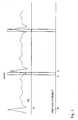
Figur 1 einen Herzzyklus-Signal mit einem Zeitfenster, in dem die Signal-Aufnahme erfolgt,Figur 2 ein Ausführungsbeispiel einer Schaltung zur bedarfsabhängigen Veränderung der Stimulationsrate bei einem künstlichen Herzschrittmacher sowieFigur 3 eine weitere Ausführung der erfindungsgemäßen Schaltung.
- 1 shows a cardiac cycle signal with a time window in which the signal is recorded,
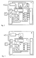
- FIG. 2 shows an exemplary embodiment of a circuit for changing the stimulation rate as required in an artificial pacemaker and
- Figure 3 shows another embodiment of the circuit according to the invention.
Die Erfindung wird in vorteilhafter Weise angewendet auf implantierbare Herzschrittmacher, welche mit einer Schaltung zur bedarfsabhängigen Veränderung der Stimulationsrate versehen sind. Die mittels der Stimulationselektrode E1 gemessene elektrische Leitfähigkeit κ im Herzen wird in Figur 1 als Herzzyklus mit Zeitfenster gezeigt.The invention is advantageously applied to implantable pacemakers which are provided with a circuit for changing the stimulation rate as required. The electrical conductivity κ measured in the heart by means of the stimulation electrode E 1 is shown in FIG. 1 as a cardiac cycle with a time window.
Es bildet insbesondere die Veränderung der elektrischen Leitfähigkeit im Herzen, als erster Parameter, ein Maß für die körperliche Belastung, welche eine entsprechende Pumpleistung (Minutenvolumen) des Herzens erfordert. Diese Größe ist unabhängig davon, ob es sich um einen geschlossenen Regelkreis oder eine Steuerung handelt, eine Eingangsgröße für die Schaltung zur bedarfsabhängigen Veränderung der Stimulationsrate 10. Die Stimulationsrate des Schrittmachers (bei Bedarfsschrittmachern die Grundrate) wird von einer Steuer- und/oder Regeleinrichtung 3 in Abhängigkeit von der für die körperliche Belastung repräsentativen Größe verändert.In particular, the change in electrical conductivity in the heart, as the first parameter, is a measure of the physical stress, which requires a corresponding pumping power (minute volume) of the heart. Regardless of whether it is a closed control loop or a controller, this variable is an input variable for the circuit for changing the
Diese repräsentative Größe ist die Steigung S der elektrischen Leitfähigkeit κ vorzugsweise im rechten Ventrikel, d.h. die Differenz der elektrischen Leitfähigkeit Δκ am Anfang und Ende eines bestimmten vorgebbaren Zeitintervalls Δtij.This representative variable is the slope S of the electrical conductivity κ, preferably in the right ventricle, ie the difference in the electrical conductivity Δκ at the beginning and end of a specific predeterminable time interval Δt ij .
Dafür wird ein Zeitfenster ![]()
![]()
Die Veränderung (Steigung) des Kurzzeitintegrals der elektrischen Leitfähigkeit innerhalb eines bestimmten Zeitfensters im Herzzyklus bildet somit mindestens mittelbar eine Eingangsgröße für die Schaltung zur bedarfsabhängigen Veränderung der Stimulationsrate 10.The change (slope) of the short-term integral of the electrical conductivity within a certain time window in the cardiac cycle thus forms at least indirectly an input variable for the circuit for changing the
Gemäß einer vorteilhaften Weiterbildung der Erfindung wird nun dasjenige Zeitintervall (Zeitfenster) ermittelt und zur späteren Differenzbildung (Steigungsermittlung) der gemessenen Leitfähigkeitswerte herangezogen, bei dem der Unterschied für zwei verschiedene Belastungszustände des Patienten ein Maximum bildet. Eine andere Variante besteht darin, daß zwischen verschiedenen räumlich unterschiedlich plazierten Elektroden umgeschaltet wird, bis ein Signal gefunden wird, welches bei dem betreffenden Parameter, in Abhängigkeit von dem die Beeinflussung einer Größe im Körper des Patienten erfolgen soll, die größte Signifikanz hat.According to an advantageous development of the invention, that time interval (time window) is now determined and used for later difference formation (slope determination) of the measured conductivity values, in which the difference forms a maximum for two different load conditions of the patient. Another variant consists in switching between different spatially different electrodes until a signal is found which has the greatest significance for the parameter in question, depending on which size is to be influenced in the patient's body.
Für das Ausführungsbeispiel des implantierbaren Herzschrittmachers ist in Figur 2 eine Schaltung zur bedarfsabhängigen Veränderung der Stimulationsrate 10 dargestellt. Die im Herzen mittels der Stimulationselektrode E1 gemessene elektrische Leitfähigkeit κ wird in einer ersten Eingangsschaltung 1 und zweiten Eingangsschaltung 2 verarbeitet und bildet eine Eingangsgröße für eine Steuer- und/oder Regeleinrichtung 3 in der Schaltung zur bedarfsabhängigen Veränderung der Stimulationsrate 10.For the exemplary embodiment of the implantable cardiac pacemaker, a circuit for changing the
Das über geeignete Aufnahmepunkte an der Stimulationselektrode E1 im rechten Ventrikel ermittelte und von der ersten zur zweiten Eingangsschaltung 2 übermittelte verstärkte Leitfähigkeitssignal wird in der zweiten Eingangsschaltung 2 in dem Zeitintervall integriert, um kurzzeitige, das Meßsignal verfälschende Schwankungen auszuschalten.The amplified conductivity signal ascertained via suitable pick-up points on the stimulation electrode E1 in the right ventricle and transmitted from the first to the
Die Eingangsschaltung 2 ist über einen Analog/Digital-Umsetzer 7 und die Eingangsschaltung 1 mit der Steuer- und/oder Regeleinrichtung 3, insbesondere mit ihrem Ein-/Ausgabe-Kanal 15, verbunden. Diese enthält neben dem Ein-/Ausgabe-Kanal 15 eine Logik bzw. vorzugsweise einen Prozessor 11, außerdem für den Speicheranschluß geeignete Auswahlschaltungen 4, 5, 9 und eine Datenein-/ausgabe-Schaltung 15 für die Steigungsgrenzwerte, eine die Steuerung des Variationsbereiches vornehmende Ratenauswahlschaltung 8 und einen Taktgeber 16.The
Die Steuer- und/oder Regelschaltung 3 ist einerseits mit ihren zwei Schaltungen 4 und 9 zur Auswahl der Zeitintervalle mit der zweiten Eingangsschaltung 2 sowie mit einer Speicherbereichsauswahlschaltung 5 und mit einem Speicher 6 verbunden. In weiterer Ausgestaltung ist am Speicher 6 zur Speicherung von Grenzwerten für den ersten Parameter auch die Daten-Ein/Ausgabe-Schaltung 15 angeschlossen. Andererseits ist die Steuer- und/oder Regelschaltung 3 mit ihrem Ein-/Ausgabe-Kanal 15 mit einer Stimulationssignalausgangsschaltung 17 verbunden.The control and / or regulating
Die Schaltung zur bedarfsabhängigen Veränderung der Stimulationsrate 10 weist ferner eine mit der Steuer- und/oder Regelschaltung 3 gekoppelte Kommunikationseinheit 18 auf. Letztere dient neben der Programmierung des implantierten Herzschrittmachers der Übermittlung von Daten an externe Programmier- und Überwachungseinheiten.The circuit for changing the
Gesteuert vom Prozessor 11, wird über die am Speicher 6 ebenfalls angeschlossene Speicherbereichsauswahlschaltung 5 ein Speicherbereich angewählt. Nun wird dasjenige Zeitintervall (Zeitfenster) ausgegeben, bei dem der Unterschied für zwei verschiedene Belastungszustände des Patienten ein Maximum bildet. Gesteuert über den Prozessor 11, erfolgt dabei über die Auswahlschaltung 5 die Auswahl der Daten im Speicher 6.Controlled by the
Dazu ist es zuvor erforderlich, eine Meßreihe bei verschiedenen körperlichen Belastungen aufzunehmen, bei denen das jeweilige Zeitfenster variiert wird. Hierzu weist die Steuer- und/oder Regeleinrichtung 3 eine Schaltung 9 zur Auswahl des Zeitfensterabstandes Δti vom Bezugspunkt to auf. Die Auswahlschaltungen 4, 5 und 9 enthalten entweder unabhängige, von der Steuer- und Regeleinrichtung 3 ansteuerbare Vor-/Rückwärtszähler oder sind in vorteilhafter Weise softwaremäßig in dem Prozessor 11 realisiert, der insbesondere die Meßwerte auswertet und die Bereiche mit maximaler Steigung Δκmax automatisch für eine feste Einstellung (Speicherung im Speicher 6) findet.To do this, it is necessary to record a series of measurements with different physical loads during which the respective time window is varied. For this purpose, the control and / or regulating
Zunächst wird bei der niedrigsten Belastungsstufe Bo nacheinander in einzelnen Herzzyklen jeweils für unterschiedliche Zeitfenster der zugehörige erste Parameter Δκoij ermittelt, wobei die Länge der Zeitintervalle Δti und Δtj variiert wird. Bei der Belastungsstufe B1 wird ein erstes Zeitfenster mit zugehörigem ersten Parameter Δκ1ij im Speicher 6 abgespeichert. Tritt bei dieser Belastungsstufe ein Zeitfenster mit den Zeitintervallen Δtm und Δtl sowie ein zugehöriger erster Parameter auf, auf den die Ungleichung ![]()
![]()
Einer Belastungsstufe Bo ist damit genau ein Zeitfenster Zij mit den Zeitintervallen Δti + Δtj zugeordnet. So wird insbesondere unter Verwendung eines mit der Speicherbereichsauswahlschaltung 5 gekoppelten Prozessors 11 für mindestens eine weitere Belastungsstufe B1 im Belastungsbereich dasjenige Zeitfenster in seiner relativen Lage zu einem festen Bezugspunkt im Herzyklus (Grenzen der Preejection-period) festgehalten, bei dem der Unterschied der Steigung des Integrals der Leitwerte ein Maximum bildet.Exactly one time window Z ij with the time intervals Δt i + Δt j is assigned to a load level B o . Thus, in particular using a
Dabei kommt es auf die absoluten Werte der Steigungen an, welche im durchlaufenen Bereich durchaus auch das Vorzeichen wechseln können. Auch ist vorteilhaft, daß nur Bereiche der in Figur 1 gezeigten Kurve mit monotoner Steigung berücksichtigt werden.It depends on the absolute values of the gradients, which can also change the sign in the area covered. It is also advantageous that only regions of the curve shown in FIG. 1 with a monotonous slope are taken into account.
Eine bevorzugte Ausführung der Erfindung wird anhand der Figur 3 näher dargestellt. Sie zeigt eine Ausführung der Schaltung zur bedarfsabhängigen Veränderung der Stimulationsrate 10, in der die Ermittlung des Bezugszeitpunktes to und die Bildung des Kurzzeitintegrals vom Prozessor 11 selbst vorgenommen wird. Der Prozessor 11 ist über eine Schaltung 19 mit dem Speicher 6 verbunden. Die mittels der Stimulationselektrode E1 gemessene elektrische Leitfähigkeit κ im Herzen wird, über eine Eingangsschaltung 1 verstärkt, dem Analog-Digital- Umsetzer 7 zugeführt, der mit dem Ein-/Ausgabe-Kanal 14 verbunden ist. Ein Integrator 2 und die zugehörigen Verbindungen können entfallen, da die Integration softwaremäßig vorgenommen wird. Die ermittelte Steigung S der elektrischen Leitfähigkeit κ vorzugsweise im rechten Ventrikel, d.h. die Differenz der elektrischen Leitfähigkeit Δκij am Anfang und Ende eines bestimmten vorgebbaren Zeitintervalls Δtij, dient der Ratenauswahlschaltung 8 zur Veränderung der Stimulationsrate des Herzschrittmachers.A preferred embodiment of the invention is shown in more detail with reference to FIG. 3. It shows an embodiment of the circuit for changing the
Innerhalb des Zeitfensters ![]()
![]()
Bei den die Bezugswerte bildenden unterschiedlichen Belastungszuständen handelt es sich einerseits bevorzugt um einen ersten Zustand kleiner körperlicher Belastung Bo (Ruhezustand) und andererseits um einen zweiten Zustand im Bereich relativ großer körperlicher Belastung B1 (Arbeitszustand). Die mathematische Auswertung der Differenzen der Integrale erfolgt vorzugsweise nach der Simpsonschen Regel, so daß sich der Rechenaufwand eines in der Schrittmacherschaltung vorhandenen Prozessors sehr stark verringert.The different stress states forming the reference values are, on the one hand, preferably a first state of small physical stress B o (rest state) and, on the other hand, a second state in the region of relatively high physical stress B 1 (working state). The mathematical evaluation of the differences of the integrals is preferably carried out according to Simpson's rule, so that the computing effort of a processor present in the pacemaker circuit is reduced considerably.
Auch kann der gesamte bei Belastungswechsel zu durchlaufende Bereich in eine Anzahl aufeinander folgender Belastungszonenbereiche unterteilt werden, denen Belastungsstufen zuordenbar sind. Zur n-ten Belastungsstufe Bn wird dann genau ein Zeitfenster Zij mit den Zeitintervallen Δti und Δtj ermittelt und dafür gesorgt, daß umschaltbare Zwischenbereiche für unterschiedliche Belastungszonenbereiche vorhanden sind.The entire area to be covered when the load changes can also be divided into a number of successive load zone areas can be divided, to which load levels can be assigned. For the nth load level B n , exactly one time window Z ij with the time intervals Δt i and Δt j is then determined and it is ensured that switchable intermediate areas are available for different load zone areas.
Die Umschaltung der Beeinflussung des ersten durch den zweiten Parameter erfolgt hierbei beispielsweise mittels eines zusätzlich vorgesehenen Aktivitätssensors 12, der die Intensität der Bewegungen oder sonstigen körperlichen Tätigkeit erfaßt. Der Aktivitätssensor 12 ist mit dem Prozessor 11 über eine dritte Eingangsschaltung 13 der Steuer-und/oder Regeleinrichtung 3 verbunden. Der Prozessor 11 steuert über die Datenein-/ausgabe-Schaltung 15 für die jeweilige Belastungsstufe die Einspeicherung und den Abruf entweder eines Wertes Δκmax bei fest vorgegebener unterer Leitwertsgrenze κi oder der Grenzwerte κi und κj in den bzw. aus dem Speicher 6. Entsprechend den Grenzwerten gibt die Ratenauswahlschaltung 8 die Simulationsrate vor. Unter Verwendung des Prozessors 11 kann auch die Ratenauswahlschaltung 8 softwaremäßig realisiert werden.The switching of the influencing of the first by the second parameter takes place here, for example, by means of an additionally provided
Ein derartiger Aktivitätssensor 12 kann dabei auch zur Selbsteichung oder Kontrolle in der Weise dienen, daß bestimmt wird, welchen ermittelten Leitfähigkeitsänderungen bestimmte Stimulationsraten zuzuordnen sind.Such an
Bei einer anderen bevorzugten Ausführungsform, ohne die dritte Eingangsschaltung, erfolgt die Umschaltung der Beeinflussung des ersten durch den zweiten Parameter durch das Ausgangssignal der Schaltung zur bedarfsabhängigen Veränderung der Stimulationsrate 10 selbst. Gegebenenfalls wird mit Hysterese dann umgeschaltet, wenn der Prozessor eine Steigung (Δκmax im Zeitfenster) ermittelt, der bereits eine andere Belastungsstufe Bn+1 zuordenbar ist. Voraussetzung ist dafür, daß das System selbstadaptierend ist, d.h. während der Stimulation versucht wird, ob sich Bereiche größerer Steigungsänderung finden lassen.In another preferred embodiment, without the third input circuit, the influencing of the first by the second parameter is switched over the output signal of the circuit for changing the
Die Schaltungstechnik eines ratengesteuerten Schrittmachers kann als bekannt unterstellt werden, wobei es bei dieser Weiterbildung der vorliegenden Erfindung darauf ankommt, die Signalaufnahme des die Stimulationsrate bestimmenden Parameters zu verbessern. Dabei ist die Anwendung der Erfindung nicht davon abhängig, ob es sich dabei um eine open-loop oder closed-loop-Steuerung handelt.The circuit technology of a rate-controlled pacemaker can be assumed to be known, with this development of the present invention it is important to improve the signal recording of the parameter determining the stimulation rate. The application of the invention is not dependent on whether it is an open-loop or closed-loop control.
Claims (17)
- Medical equipment for producing a treatment value for a patient dependent on at least one variable parameter which is determined inside the body and forms a first input value, the change in the first parameter being dependent on a second parameter which may possibly also form an input value,
characterised by
means for changing the treatment value with variation of the second parameter, in such a way that the difference in the values of the first parameter is at a maximum at the limits of the variation range of the first parameter, which arises with the change in the treatment value within an envisaged variation range of the patient's treatment value,
a memory in which the value of the second parameter, for which the difference in the values of the first parameter is at a maximum, is retained and
control means for changing the treatment value dependent on the first parameter while maintaining the previously stored second parameter. - The equipment of claim 1, characterised in that switch-over means are provided to allocate different variation ranges of the first parameter each to different second parameters.
- The equipment of claim 2, characterised in that additional switching means are provided to switch over between different variation ranges of the first parameter, dependent on a third parameter obtained inside the patient's body.
- The equipment of any of the preceding claims, characterised in that the second parameter is a time window of signal reception in a cyclic process, or is the position of electrodes which are spatially differently located in the body.
- The equipment of any of the preceding claims, in the form of a cardiac pacemaker comprising a circuit for changing the stimulation rate as required, wherein the time change in electrical conductivity in the heart, as the first parameter, forms a measure of the physical strain and of the necessary pumping action of the heart and thus forms an input value for the circuit for changing the stimulation rate as required,
characterised in that
the difference in electrical conductivity at the beginning and end of the period of time within the cardiac cycle which constitutes a second parameter and which is varied within a series of measurements, or the rise in electrical conductivity in the period of time forms the first parameter, and that that concrete period of time within the cardiac cycle is stored as the value of the second parameter, in which the difference between the first parameter values measured with the patient in two different states of strain is at a maximum. - The cardiac pacemaker of claim 5, characterised in that the different states of strain are a resting state i.e. a range of low physical strain, and a working state, i.e. a range of relatively high physical strain.
- The cardiac pacemaker of claim 6, characterised in that the absolute differential values of the first parameter between the beginning and end of the period of time are used for computation.
- The cardiac pacemaker of claim 6 or 7, characterised in that the integrals of the path in time of the electrical conductivities are evaluated.
- The cardiac pacemaker of claim 8, characterised in that the integrals are evaluated by Simpson's rule.
- The cardiac pacemaker of any of claims 6 to 9, characterised in that gradients with a different preceding sign are also taken into account.
- The cardiac pacemaker of any of the preceding claims, characterised in that only ranges with a monotonic gradient are taken into account.
- The cardiac pacemaker of any of claims 6 to 11, characterised in that means are provided for switching over between different states of strain.
- The cardiac pacemaker of any of claims 3 to 11 and claim 12, characterised in that the switch-over between the variation ranges of the first parameter takes place under the control of an additional activity sensor.
- The cardiac pacemaker of claim 13, characterised in that the activity sensor also supplies a calibrating signal.
- The cardiac pacemaker of any of claims 6 to 14, characterised in that the switch-over between ranges of different strain takes place under the control of the activity sensor.
- The cardiac pacemaker of any of claims 6 to 15, characterised in that the switch-over between ranges of different strain takes place, possibly with hysteresis, by means of the output signal from the circuit for changing the actual stimulation rate dependent on the strain.
- The cardiac pacemaker of any of claims 6 to 16, characterised by construction for self-adapting operation, in such a way that conductivity variation ranges with little change in the gradient are automatically replaced as the control value by ranges with a greater change in the gradient, during operation.
Applications Claiming Priority (3)
| Application Number | Priority Date | Filing Date | Title |
|---|---|---|---|
| DE4109202 | 1991-03-18 | ||
| DE4109202 | 1991-03-18 | ||
| PCT/DE1992/000238 WO1992016256A1 (en) | 1991-03-18 | 1992-03-18 | Medical appliance for generating a therapeutical parameter |
Publications (3)
| Publication Number | Publication Date |
|---|---|
| EP0576509A1 EP0576509A1 (en) | 1994-01-05 |
| EP0576509B1 true EP0576509B1 (en) | 1996-07-03 |
| EP0576509B2 EP0576509B2 (en) | 2007-11-14 |
Family
ID=6427829
Family Applications (1)
| Application Number | Title | Priority Date | Filing Date |
|---|---|---|---|
| EP92906803A Expired - Lifetime EP0576509B2 (en) | 1991-03-18 | 1992-03-18 | Medical appliance for generating a therapeutical parameter |
Country Status (4)
| Country | Link |
|---|---|
| US (1) | US5431690A (en) |
| EP (1) | EP0576509B2 (en) |
| DE (1) | DE59206710D1 (en) |
| WO (1) | WO1992016256A1 (en) |
Families Citing this family (18)
| Publication number | Priority date | Publication date | Assignee | Title |
|---|---|---|---|---|
| US5307263A (en) | 1992-11-17 | 1994-04-26 | Raya Systems, Inc. | Modular microprocessor-based health monitoring system |
| US9215979B2 (en) | 1992-11-17 | 2015-12-22 | Robert Bosch Healthcare Systems, Inc. | Multi-user remote health monitoring system |
| US20010011224A1 (en) | 1995-06-07 | 2001-08-02 | Stephen James Brown | Modular microprocessor-based health monitoring system |
| US8027809B2 (en) | 1992-11-17 | 2011-09-27 | Health Hero Network, Inc. | Home power management system |
| US6968375B1 (en) | 1997-03-28 | 2005-11-22 | Health Hero Network, Inc. | Networked system for interactive communication and remote monitoring of individuals |
| WO2001037174A1 (en) | 1992-11-17 | 2001-05-25 | Health Hero Network, Inc. | Method and system for improving adherence with a diet program or other medical regimen |
| US8078431B2 (en) | 1992-11-17 | 2011-12-13 | Health Hero Network, Inc. | Home power management system |
| US8095340B2 (en) | 1992-11-17 | 2012-01-10 | Health Hero Network, Inc. | Home power management system |
| US7624028B1 (en) | 1992-11-17 | 2009-11-24 | Health Hero Network, Inc. | Remote health monitoring and maintenance system |
| US5956501A (en) * | 1997-01-10 | 1999-09-21 | Health Hero Network, Inc. | Disease simulation system and method |
| US5951300A (en) | 1997-03-10 | 1999-09-14 | Health Hero Network | Online system and method for providing composite entertainment and health information |
| US6330426B2 (en) | 1994-05-23 | 2001-12-11 | Stephen J. Brown | System and method for remote education using a memory card |
| US5832448A (en) | 1996-10-16 | 1998-11-03 | Health Hero Network | Multiple patient monitoring system for proactive health management |
| US8078407B1 (en) | 1997-03-28 | 2011-12-13 | Health Hero Network, Inc. | System and method for identifying disease-influencing genes |
| US6032119A (en) | 1997-01-16 | 2000-02-29 | Health Hero Network, Inc. | Personalized display of health information |
| DE19804843A1 (en) * | 1998-01-29 | 1999-08-05 | Biotronik Mess & Therapieg | Self-calibrating rate-adaptive pacemaker |
| US8521546B2 (en) | 1998-09-25 | 2013-08-27 | Health Hero Network | Dynamic modeling and scoring risk assessment |
| US7399276B1 (en) | 2003-05-08 | 2008-07-15 | Health Hero Network, Inc. | Remote health monitoring system |
Citations (3)
| Publication number | Priority date | Publication date | Assignee | Title |
|---|---|---|---|---|
| EP0215731A2 (en) * | 1985-09-17 | 1987-03-25 | BIOTRONIK Mess- und Therapiegeräte GmbH & Co Ingenieurbüro Berlin | Heart stimulator |
| EP0225839A1 (en) * | 1985-09-17 | 1987-06-16 | BIOTRONIK Mess- und Therapiegeräte GmbH & Co Ingenieurbüro Berlin | Heart pacemaker |
| US4992907A (en) * | 1989-05-12 | 1991-02-12 | Hewlett-Packard Company | Electrostatic discharge protection system |
Family Cites Families (7)
| Publication number | Priority date | Publication date | Assignee | Title |
|---|---|---|---|---|
| US4280502A (en) * | 1979-08-08 | 1981-07-28 | Intermedics, Inc. | Tachycardia arrester |
| US4303075A (en) * | 1980-02-11 | 1981-12-01 | Mieczyslaw Mirowski | Method and apparatus for maximizing stroke volume through atrioventricular pacing using implanted cardioverter/pacer |
| EP0222681B1 (en) * | 1985-09-17 | 1995-03-08 | BIOTRONIK Mess- und Therapiegeräte GmbH & Co Ingenieurbüro Berlin | Heart pacemaker |
| DE3533597A1 (en) * | 1985-09-18 | 1987-04-16 | Biotronik Mess & Therapieg | HEART PACEMAKER |
| US4766901A (en) * | 1985-12-18 | 1988-08-30 | Telectronics N.V. | Rate responsive pacing system using the integrated evoked potential |
| DE3631155A1 (en) * | 1986-09-12 | 1988-03-24 | Alt Eckhard | FREQUENCY VARIABLE HEART PACEMAKER WITH STRESS-ADEQUATE FREQUENCY BEHAVIOR |
| US4905696A (en) * | 1987-10-07 | 1990-03-06 | Siemens Aktiengesellschaft | Method and apparatus for P-synchronously stimulating the heart of a patient |
-
1992
- 1992-03-18 DE DE59206710T patent/DE59206710D1/en not_active Expired - Lifetime
- 1992-03-18 EP EP92906803A patent/EP0576509B2/en not_active Expired - Lifetime
- 1992-03-18 US US08/119,142 patent/US5431690A/en not_active Expired - Lifetime
- 1992-03-18 WO PCT/DE1992/000238 patent/WO1992016256A1/en active IP Right Grant
Patent Citations (3)
| Publication number | Priority date | Publication date | Assignee | Title |
|---|---|---|---|---|
| EP0215731A2 (en) * | 1985-09-17 | 1987-03-25 | BIOTRONIK Mess- und Therapiegeräte GmbH & Co Ingenieurbüro Berlin | Heart stimulator |
| EP0225839A1 (en) * | 1985-09-17 | 1987-06-16 | BIOTRONIK Mess- und Therapiegeräte GmbH & Co Ingenieurbüro Berlin | Heart pacemaker |
| US4992907A (en) * | 1989-05-12 | 1991-02-12 | Hewlett-Packard Company | Electrostatic discharge protection system |
Non-Patent Citations (1)
| Title |
|---|
| Max Schaldach: "Automatic Adjustment of Pacing Parameters Based on Intracardiac Impedance Measurements" from Pacing and Clinical Electrophysiology (PACE) Vol. 13, December 1990, Part II, pages 1702-1710 * |
Also Published As
| Publication number | Publication date |
|---|---|
| DE59206710D1 (en) | 1996-08-08 |
| US5431690A (en) | 1995-07-11 |
| EP0576509B2 (en) | 2007-11-14 |
| EP0576509A1 (en) | 1994-01-05 |
| WO1992016256A1 (en) | 1992-10-01 |
Similar Documents
| Publication | Publication Date | Title |
|---|---|---|
| EP0576509B1 (en) | Medical appliance for generating a therapeutical parameter | |
| DE69733531T2 (en) | Medical device | |
| DE68919425T3 (en) | Pacemaker with improved automatic output control. | |
| DE69233272T2 (en) | METHOD AND DEVICE FOR REGULATING ENERGY IN STIMULATING IN A HEART PACEMAKER | |
| EP0793976B1 (en) | Rate adaptive pacemaker | |
| EP1518495B1 (en) | Method and device for continuous monitoring of analyte concentration | |
| EP0215729B1 (en) | Heart stimulator | |
| DE69836558T2 (en) | METHOD AND DEVICE FOR DETERMINING A CONCENTRATION | |
| EP0793980B1 (en) | Signal storage device in an implantable medical apparatus | |
| DE2803366C2 (en) | ||
| DE69726356T2 (en) | Apparatus for deriving a component of an evoked response from a sampled cardiac signal by suppressing electrode polarization components | |
| EP0170997A1 (en) | Device for the physiological frequence control of a heart pacemaker using an excitation electrode | |
| EP0783902B1 (en) | Extracorporal control device for an implantable medical device | |
| EP0464252B1 (en) | Device for tissue stimulation | |
| EP0228985A1 (en) | Heart pacemaker | |
| DE3243094A1 (en) | IMPLANTABLE IRRITATING DEVICE | |
| EP0813891A2 (en) | Signal detector | |
| EP0108360A1 (en) | Heart pacemaker for arresting a tachycardia | |
| DE60013874T2 (en) | AUTOMATIC RATE ADAPTIVE HEART STIMULATION WITH AUTOMATIC LIFESTYLE ADAPTATION | |
| DE10211766B4 (en) | Device for treating patients by means of brain stimulation and the use of the device in medicine | |
| DE19900690C1 (en) | Heart pacemaker reduces and increases stimulation interval so that mean interval does not change and determines electrical restitution of heart for this mean interval by measuring action potential duration | |
| EP1262143B1 (en) | Method and apparatus for storing heart signal data | |
| DE69632673T2 (en) | Pacemaker with evoked response detection | |
| DE60320406T2 (en) | DEVICE FOR MONITORING AND STIMULATING THE HEART; A SUCH DEVICE CONTAINING SYSTEM | |
| DE10006154A1 (en) | Process for calculating the heart rate variability for use in an EKG monitor and EKG monitor with a corresponding calculation program |
Legal Events
| Date | Code | Title | Description |
|---|---|---|---|
| PUAI | Public reference made under article 153(3) epc to a published international application that has entered the european phase |
Free format text: ORIGINAL CODE: 0009012 |
|
| 17P | Request for examination filed |
Effective date: 19930929 |
|
| AK | Designated contracting states |
Kind code of ref document: A1 Designated state(s): DE FR NL |
|
| 17Q | First examination report despatched |
Effective date: 19950324 |
|
| GRAH | Despatch of communication of intention to grant a patent |
Free format text: ORIGINAL CODE: EPIDOS IGRA |
|
| GRAA | (expected) grant |
Free format text: ORIGINAL CODE: 0009210 |
|
| AK | Designated contracting states |
Kind code of ref document: B1 Designated state(s): DE FR NL |
|
| PG25 | Lapsed in a contracting state [announced via postgrant information from national office to epo] |
Ref country code: NL Free format text: LAPSE BECAUSE OF FAILURE TO SUBMIT A TRANSLATION OF THE DESCRIPTION OR TO PAY THE FEE WITHIN THE PRESCRIBED TIME-LIMIT Effective date: 19960703 |
|
| REF | Corresponds to: |
Ref document number: 59206710 Country of ref document: DE Date of ref document: 19960808 |
|
| GRAH | Despatch of communication of intention to grant a patent |
Free format text: ORIGINAL CODE: EPIDOS IGRA |
|
| ET | Fr: translation filed | ||
| ET | Fr: translation filed | ||
| NLV1 | Nl: lapsed or annulled due to failure to fulfill the requirements of art. 29p and 29m of the patents act | ||
| PLAV | Examination of admissibility of opposition |
Free format text: ORIGINAL CODE: EPIDOS OPEX |
|
| PLBQ | Unpublished change to opponent data |
Free format text: ORIGINAL CODE: EPIDOS OPPO |
|
| PLBI | Opposition filed |
Free format text: ORIGINAL CODE: 0009260 |
|
| 26 | Opposition filed |
Opponent name: PACESETTER AB Effective date: 19970403 |
|
| PLAV | Examination of admissibility of opposition |
Free format text: ORIGINAL CODE: EPIDOS OPEX |
|
| PLBF | Reply of patent proprietor to notice(s) of opposition |
Free format text: ORIGINAL CODE: EPIDOS OBSO |
|
| PLBF | Reply of patent proprietor to notice(s) of opposition |
Free format text: ORIGINAL CODE: EPIDOS OBSO |
|
| RDAH | Patent revoked |
Free format text: ORIGINAL CODE: EPIDOS REVO |
|
| APAC | Appeal dossier modified |
Free format text: ORIGINAL CODE: EPIDOS NOAPO |
|
| APAE | Appeal reference modified |
Free format text: ORIGINAL CODE: EPIDOS REFNO |
|
| APAE | Appeal reference modified |
Free format text: ORIGINAL CODE: EPIDOS REFNO |
|
| APAC | Appeal dossier modified |
Free format text: ORIGINAL CODE: EPIDOS NOAPO |
|
| PLAB | Opposition data, opponent's data or that of the opponent's representative modified |
Free format text: ORIGINAL CODE: 0009299OPPO |
|
| R26 | Opposition filed (corrected) |
Opponent name: ST. JUDE MEDICAL AB Effective date: 19970403 |
|
| APBU | Appeal procedure closed |
Free format text: ORIGINAL CODE: EPIDOSNNOA9O |
|
| RAP2 | Party data changed (patent owner data changed or rights of a patent transferred) |
Owner name: BIOTRONIK GMBH & CO. KG |
|
| PLAY | Examination report in opposition despatched + time limit |
Free format text: ORIGINAL CODE: EPIDOSNORE2 |
|
| PLAY | Examination report in opposition despatched + time limit |
Free format text: ORIGINAL CODE: EPIDOSNORE2 |
|
| PLBC | Reply to examination report in opposition received |
Free format text: ORIGINAL CODE: EPIDOSNORE3 |
|
| APAH | Appeal reference modified |
Free format text: ORIGINAL CODE: EPIDOSCREFNO |
|
| PLAB | Opposition data, opponent's data or that of the opponent's representative modified |
Free format text: ORIGINAL CODE: 0009299OPPO |
|
| R26 | Opposition filed (corrected) |
Opponent name: ST. JUDE MEDICAL AB Effective date: 19970403 |
|
| PUAH | Patent maintained in amended form |
Free format text: ORIGINAL CODE: 0009272 |
|
| STAA | Information on the status of an ep patent application or granted ep patent |
Free format text: STATUS: PATENT MAINTAINED AS AMENDED |
|
| 27A | Patent maintained in amended form |
Effective date: 20071114 |
|
| AK | Designated contracting states |
Kind code of ref document: B2 Designated state(s): DE FR NL |
|
| ET3 | Fr: translation filed ** decision concerning opposition | ||
| PGFP | Annual fee paid to national office [announced via postgrant information from national office to epo] |
Ref country code: FR Payment date: 20110401 Year of fee payment: 20 |
|
| PGFP | Annual fee paid to national office [announced via postgrant information from national office to epo] |
Ref country code: DE Payment date: 20110228 Year of fee payment: 20 |
|
| REG | Reference to a national code |
Ref country code: DE Ref legal event code: R082 Ref document number: 59206710 Country of ref document: DE |
|
| REG | Reference to a national code |
Ref country code: DE Ref legal event code: R081 Ref document number: 59206710 Country of ref document: DE Owner name: BIOTRONIK SE & CO. KG, DE Free format text: FORMER OWNER: BIOTRONIK MESS- UND THERAPIEGERAETE GMBH & CO. INGENIEURBUERO BERLIN, 12359 BERLIN, DE Effective date: 20111219 |
|
| REG | Reference to a national code |
Ref country code: DE Ref legal event code: R071 Ref document number: 59206710 Country of ref document: DE |
|
| REG | Reference to a national code |
Ref country code: DE Ref legal event code: R071 Ref document number: 59206710 Country of ref document: DE |
|
| PG25 | Lapsed in a contracting state [announced via postgrant information from national office to epo] |
Ref country code: DE Free format text: LAPSE BECAUSE OF EXPIRATION OF PROTECTION Effective date: 20120319 |