EP0576882A2 - Modem with digital isolation - Google Patents
Modem with digital isolation Download PDFInfo
- Publication number
- EP0576882A2 EP0576882A2 EP93109223A EP93109223A EP0576882A2 EP 0576882 A2 EP0576882 A2 EP 0576882A2 EP 93109223 A EP93109223 A EP 93109223A EP 93109223 A EP93109223 A EP 93109223A EP 0576882 A2 EP0576882 A2 EP 0576882A2
- Authority
- EP
- European Patent Office
- Prior art keywords
- digital
- analog
- modem
- isolation
- signals
- Prior art date
- Legal status (The legal status is an assumption and is not a legal conclusion. Google has not performed a legal analysis and makes no representation as to the accuracy of the status listed.)
- Granted
Links
Images

Classifications
-
- H—ELECTRICITY
- H04—ELECTRIC COMMUNICATION TECHNIQUE
- H04M—TELEPHONIC COMMUNICATION
- H04M11/00—Telephonic communication systems specially adapted for combination with other electrical systems
- H04M11/06—Simultaneous speech and data transmission, e.g. telegraphic transmission over the same conductors
Definitions
- the invention relates to modems and, more particularly, eliminates the relatively large isolation transformer from the modem while changing isolation from the analog signal region to the digital signal region to avoid analog distortion, and obviate the isolation transformer.
- DAA Data Access Arrangement
- Modem size is decreasing. Modems are becoming an integral part of all LapTop/PalmTop computers. Because these computers are small, size and weight are at a premium. With the growing data rates, minimum distortion is a must. Distortion is one of the limiting factor for high speed modems.
- the DAA interface circuitry has remained relatively unchanged. In fact, on some of the lap top designs, the DAA occupies almost as much room as the remainder of the modem circuitry.
- the transformer One of the largest components in the DAA is the transformer. Functionally the transformer satisfies two design requirements.
- the new high performance modems like v32, require distortion levels of -70dBm or lower. To achieve these levels require special magnetic material and large physical size.
- the invention eliminates the large isolation transformer and provides isolation at the digital interface after conversion from an analog incoming signal and before the conversion to an outgoing analog signal. At this point it is possible to provide the isolation with much less concern with analog distortion.
- the novel isolation is preferably magnetic, in the form of two tiny pulse transformers. Other digital isolation methods, such as optical are also novel and applicable.
- the Rockwell modem architecture provides an ideal structure to incorporate the isolation circuitry. This is between the Digital Signal Processor (DSP or CSPX) and the Integrated Analog (IA) device. Functionally, the signals at this interface are digital, and the data rates are moderate. Currently the interface between the CSPX and the IA consists of about 15 discrete lines, which include data, timing and control.
- DSP Digital Signal Processor
- IA Integrated Analog
- serial data streams are combined into two serial data streams, one input, and one output.
- the data is encoded in a time division multiplex, self clocking scheme. All serial encoding and decoding is incorporated within the CSPX and IA devices.
- the modem For the above water/ground telephone systems, the modem must pass a metallic voltage surge test which is a pulse of 800 volts applied between the TIP and RING of the modem. While the modem is at the ON-HOOK state, there is no problem because the seizure relay is off (open), and thus, prevents the surge from getting into the electronic circuits. This 800v surge is also applied while the modem is in the OFF-HOOK state, at which time the line switch is closed and the 800v can cause an irreversible damage to our electronic circuits.
- a synergistic result is obtained if the above invention is combined with a detector circuit which senses the appearance of the high level, fast rising surge in the DAA.
- This circuit disengages the electronics from the line before the surge can reach damaging magnitudes.
- the active rejection circuit serves as a surge protection unit - replaces the metal oxide varistor (MOV) and the isolation transformer, and provides line seizure switch replacement for the traditional relay. Component count is reduced by removing the transformer, MOV and the relay.
- the Rockwell modem includes Data Access Arrangement (DAA)9, Integrated Analog (IA) device 11 (FIG. 1) and the Digital Signal Processor 13 (DSP).
- DAA 9 is connected to IA 11 by wires 10
- IA 11 and DSP 13 are connected by 15 individual wires 15, with the micro processor 14 being connected to DSP 13 by several wires 16.
- All Data Access Arrangement (DAA) devices 9 and 17 (FIG. 2) require a high voltage isolation between the telephone lines 19,21 and a modem.
- transformer 21 in the DAA section 9) provides this isolation.
- FIGs. 3, 7, and 8 detail the cross-referenced invention which uses a FET to open a lead from the telephone line system upon detecting a surge in the DAA section and provides a synergistic combination with the present invention, which is best seen in FIGs. 2, 5 and 5A.
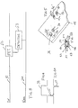
- the isolation transformer 21 has been eliminated and, instead, tiny pulsed transformers 25,27 are used between the IA device 11' and the DSP 13'.
- the received integrated analog signal is digitized, and then multiplexed in box 29 and demultiplexed in box 31, whereas the transmitted signal is multiplexed in Box 31A and demultiplexed in box 29A, thus avoiding the 15 wire interconnection and all analog distortion.
- the parallel signals on these leads (15) are combined into two serial data streams, one input and one output.
- the data is encoded in a time division multiplex, self clocking arrangement. All serial encoding and decoding is incorporated into the Integrated Analog and Digital Signal Processing devices 11' and 13', so that the isolation circuitry may consist only of two pulse transformers 25, 27 or two opto couplers (not shown).
- pulsed signals save power. It is only necessary to pass short spikes 35,37 (FIG. 4A), representing up and down transitions of original wave 39, rather than to pass the full wave 39 (FIG. 4). Common mode rejection, as well as, high voltage isolation are attained by the pulse transformers.
- FIGs. 5 and 7 show the construction of the pulse transformers 25 and 27 on conventional glass pc board 41 of, e.g. 062" thick.
- Center holes 36,38 in the board receive the legs 42,43 and 44,45 of U-bars 40,46 to form the "gaps" where they abut.
- the coils 37,39 surrounding the respective legs comprise only a few turns of metal, laid down on the board 41, and etched away to leave the coils, which may have diameters of about 1/8 inch.
- the U-bars are about 1/2 inch in length.
- the other pulse transformer 27 is spaced away from transformer 25 as far as practical, and the components are the same, bearing the primes of the same numbers.
- the best magnetic materials are employed for the magnetic path, such as ferrite, and the small dimensions easily fit space minimums.
- the frequency of operation is in the megacycle range, and the power losses are extremely low because the pulse technique requires much less power than handling the entire wave.
- the pulse technique also handles common mode distortion problems.
- Two opto couplers are also effective on two serial data streams, i.e. one input and one output, but the pulse transformer isolation uses less power.
- FIGs. 3 and 7 show surge rejection circuits for use in DAA device 17 of FIG. 2.
- TIP line 51 includes FET 52 (or a fast acting transistor) to open this line.
- DETECTOR 53 between TIP lead 51 and RING lead 54 senses the surge and very quickly opens FET 52.
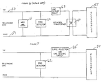
- FIG. 6 shows PRIOR ART type surge protection for modems, e.g. 57 coupled to telephone lines 58,59.
- the conventional isolation transformer 60 is shown connected between the telephone lines 58,59 and the modem 57.
- MOV 61 metal oxide varistor
- RING DETECTOR 62 is provided to indicate to modem 57 that a ring has appeared and the DSP 13, via IA11 operates LINE SEIZURE RELAY 63.
- FIG. 7 shows a preferred surge protection circuit of this invention in the absence of isolation transformer 60.
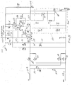
- the details of this SURGE REJECTION and LINE SEIZURE SWITCH 65 are set forth In FIG. 8.
- the ON and OFF Hook lead is shown at 101, supplying +5 volts in OFF HOOK, and the DC.
- power lead 103 receives +5 volts above ground 105 when the MODEM is on.
- FET 107 (BUZ 78) serves to open and close TIP lead in the signalling circuit for unexpected surges.
- Capacitor 110 in parallel lead 111 including series resistor 112 across TIP lead 109 and RING lead 113, is a .33 ⁇ f, 250 volt capacitor and resistor 112 is 10,000 ohms.
- the pair comprise a dummy load for the RING signal.
- a full wave bridge rectifier comprises the four 1N4006 diodes 115, 117, 119 and 121 to insure positive voltage on the drain 123 of FET 107, source 125 being grounded at 105 over lead 127.
- the circuit of FIG. 8 must provide protection under a variety of circumstances:
- ground 105 is connected to +5 volt lead 103, so a high potential spike or surge across TIP-RING causes the negative side of the pulse to pass via any or several paths in the electronic inductor box 150 up to ground 105 and to lead 103.
- the pulse is across the 5:1 voltage divider, R4 162, R6 161.
- FET 107 when FET 107 is going from ON to OFF, there is still some energy passed through it, and voltage builds up across Q14, 144. After the clock, transistor Q12 142 turns on hard by Q bar, Q going up and Q14 144 is then turned on hard, absorbing the energy.
- the surge protective circuit can work in any circuit or modem to protect, e.g., consumer products from non-common mode surges.
- the combination of the transformerless DAA with digital pulse transformers and the surge protection circuit precludes both uncommon mode and common mode problems.
- the digital isolation invention is applicable to most all modems.
- the invention may be summarized as providing a modem without a conventional isolation transformer, wherein an Integrated Analog device is connected to the Data Access Arrangement and a Microprocessor is connected to a Digital Signal Processor.
- the invention may be summarized as follows:
Abstract
Description
- This application is related to simultaneously filed US. application entitled ACTIVE SURGE REJECTION CIRCUIT by the same inventors, assigned to a common assignee.
- The invention relates to modems and, more particularly, eliminates the relatively large isolation transformer from the modem while changing isolation from the analog signal region to the digital signal region to avoid analog distortion, and obviate the isolation transformer.
- One problem of the prior art is the fact that the Data Access Arrangement (DAA), which interfaces between the telephone lines and the modem, is too large and heavy for the new "credit card" minimal size modem cards.
- Just as data speeds are growing, modem size is decreasing. Modems are becoming an integral part of all LapTop/PalmTop computers. Because these computers are small, size and weight are at a premium. With the growing data rates, minimum distortion is a must. Distortion is one of the limiting factor for high speed modems.
- Many modems available on the market today utilize an isolation transformer in the DAA section. While the transformer protects the electronic circuits, it also introduces distortion, consumes real estate and is the heaviest part of the modem section. In the case of portable computers, minimum weight is a priority requirement.
- By eliminating the transformer and the distortion that comes with it, an increase in the data rate capabilities of the modem is realized. Size, weight and cost are also reduced significantly.
- Although significant strides in improving performance and reducing the size of modems has been made, the DAA interface circuitry has remained relatively unchanged. In fact, on some of the lap top designs, the DAA occupies almost as much room as the remainder of the modem circuitry.
- So far, designers have been able to stay within the packaging constraints by squeezing the parts closer together. However, designers are quickly reaching limits as they are now experiencing problems in meeting the UL and Part 68 high voltage breakdown test. In addition, the physical size of the DAA components prevents the installation of a modem in the new pocket computers.
- One of the largest components in the DAA is the transformer. Functionally the transformer satisfies two design requirements.
- First, it provides the necessary high voltage isolation between the telephone network and the user. In the United States, this is specified by FCC part 68 which requires 1500 volts. In other countries this isolation may be up to 3750 volts.
- Second, it provides the balance interface circuit necessary to meet Part 68, as well as providing good common mode rejection of the noise signals normally on the telco lines.
- To support both of these requirements and still maintain a very low distortion level results in a relatively large transformer. For example, the new high performance modems, like v32, require distortion levels of -70dBm or lower. To achieve these levels require special magnetic material and large physical size.
- Based on these problems, it is clear that there needs to be an alternate to the analog isolation transformer.
- Experience indicates that when one attempts to add isolation circuitry in the analog circuit path, there will always be the problem of adding distortion.
- The invention eliminates the large isolation transformer and provides isolation at the digital interface after conversion from an analog incoming signal and before the conversion to an outgoing analog signal. At this point it is possible to provide the isolation with much less concern with analog distortion. The novel isolation is preferably magnetic, in the form of two tiny pulse transformers. Other digital isolation methods, such as optical are also novel and applicable.
- The Rockwell modem architecture provides an ideal structure to incorporate the isolation circuitry. This is between the Digital Signal Processor (DSP or CSPX) and the Integrated Analog (IA) device. Functionally, the signals at this interface are digital, and the data rates are moderate. Currently the interface between the CSPX and the IA consists of about 15 discrete lines, which include data, timing and control.
- These parallel signals are combined into two serial data streams, one input, and one output. The data is encoded in a time division multiplex, self clocking scheme. All serial encoding and decoding is incorporated within the CSPX and IA devices.
- For the above water/ground telephone systems, the modem must pass a metallic voltage surge test which is a pulse of 800 volts applied between the TIP and RING of the modem. While the modem is at the ON-HOOK state, there is no problem because the seizure relay is off (open), and thus, prevents the surge from getting into the electronic circuits. This 800v surge is also applied while the modem is in the OFF-HOOK state, at which time the line switch is closed and the 800v can cause an irreversible damage to our electronic circuits.
- A synergistic result is obtained if the above invention is combined with a detector circuit which senses the appearance of the high level, fast rising surge in the DAA. This circuit disengages the electronics from the line before the surge can reach damaging magnitudes. The active rejection circuit serves as a surge protection unit - replaces the metal oxide varistor (MOV) and the isolation transformer, and provides line seizure switch replacement for the traditional relay. Component count is reduced by removing the transformer, MOV and the relay.
-
- FIG. 1 is a block diagram of a prior art modem;
- FIG. 2 is a block diagram of the present invention;
- FIG. 3 shows the surge detector and a line FET;
- FIG. 4 shows a typical square wave;
- FIG. 4A shows the wave differentiated to save power;
- FIG. 5 shows coils for a pulse transformer;
- FIG. 5A is a view in cross section of a pulse transformer:
- FIG. 6 shows a prior art surge protection circuit when the isolation transformer is present;
- FIG. 7 shows the surge protection circuit in the absence of an isolation transformer; and,
- FIG. 8 is a circuit diagram of a transformer-less DAA circuit with surge protection.
- Currently, the Rockwell modem includes Data Access Arrangement (DAA)9, Integrated Analog (IA) device 11 (FIG. 1) and the Digital Signal Processor 13 (DSP).
DAA 9 is connected to IA 11 by wires 10, and IA 11 andDSP 13 are connected by 15individual wires 15, with themicro processor 14 being connected toDSP 13 by several wires 16. All Data Access Arrangement (DAA)devices 9 and 17 (FIG. 2) require a high voltage isolation between thetelephone lines - FIGs. 3, 7, and 8 detail the cross-referenced invention which uses a FET to open a lead from the telephone line system upon detecting a surge in the DAA section and provides a synergistic combination with the present invention, which is best seen in FIGs. 2, 5 and 5A.
- In FIG. 2, the
isolation transformer 21 has been eliminated and, instead, tinypulsed transformers box 31, whereas the transmitted signal is multiplexed inBox 31A and demultiplexed inbox 29A, thus avoiding the 15 wire interconnection and all analog distortion. - Thus, it may be seen that the parallel signals on these leads (15) are combined into two serial data streams, one input and one output. The data is encoded in a time division multiplex, self clocking arrangement. All serial encoding and decoding is incorporated into the Integrated Analog and Digital Signal Processing devices 11' and 13', so that the isolation circuitry may consist only of two
pulse transformers - Also, pulsed signals save power. It is only necessary to pass short spikes 35,37 (FIG. 4A), representing up and down transitions of
original wave 39, rather than to pass the full wave 39 (FIG. 4). Common mode rejection, as well as, high voltage isolation are attained by the pulse transformers. - FIGs. 5 and 7 show the construction of the
pulse transformers glass pc board 41 of, e.g. 062" thick. Center holes 36,38 in the board, receive thelegs coils board 41, and etched away to leave the coils, which may have diameters of about 1/8 inch. The U-bars are about 1/2 inch in length. Theother pulse transformer 27 is spaced away fromtransformer 25 as far as practical, and the components are the same, bearing the primes of the same numbers. The best magnetic materials are employed for the magnetic path, such as ferrite, and the small dimensions easily fit space minimums. - The frequency of operation is in the megacycle range, and the power losses are extremely low because the pulse technique requires much less power than handling the entire wave. The pulse technique also handles common mode distortion problems.
- In lieu of the preferred pulse transformers at the digital interface, other types of isolation may be used. Two opto couplers are also effective on two serial data streams, i.e. one input and one output, but the pulse transformer isolation uses less power.
- For non-common mode, e.g. lightning caused surges, i.e., in above ground telephone systems, the block diagrams of FIGs. 3 and 7 show surge rejection circuits for use in
DAA device 17 of FIG. 2. In FIG. 3,TIP line 51 includes FET 52 (or a fast acting transistor) to open this line. DETECTOR 53 betweenTIP lead 51 andRING lead 54, senses the surge and very quickly opensFET 52. - FIG. 6 shows PRIOR ART type surge protection for modems, e.g. 57 coupled to telephone lines 58,59. The conventional isolation transformer 60 is shown connected between the telephone lines 58,59 and the
modem 57. MOV 61 (metal oxide varistor) is shown connected across the lines to act as a surge absorber.RING DETECTOR 62 is provided to indicate tomodem 57 that a ring has appeared and theDSP 13, via IA11 operates LINE SEIZURE RELAY 63. - FIG. 7 shows a preferred surge protection circuit of this invention in the absence of isolation transformer 60. The details of this SURGE REJECTION and LINE SEIZURE SWITCH 65 are set forth In FIG. 8.
- In FIG. 8, the ON and OFF Hook lead is shown at 101, supplying +5 volts in OFF HOOK, and the DC.
power lead 103 receives +5 volts above ground 105 when the MODEM is on. FET 107 (BUZ 78) serves to open and close TIP lead in the signalling circuit for unexpected surges. - Capacitor 110 in parallel lead 111, including
series resistor 112 acrossTIP lead 109 and RING lead 113, is a .33 µf, 250 volt capacitor andresistor 112 is 10,000 ohms. The pair comprise a dummy load for the RING signal. - Next, a full wave bridge rectifier comprises the four
1N4006 diodes drain 123 ofFET 107,source 125 being grounded at 105 over lead 127. - The circuit of FIG. 8 must provide protection under a variety of circumstances:
- 1) The modem's power is OFF at 103.
At this time the FET 107 (Q4) is already in the OFF state. While in the OFF state, the FET will block high voltage from going through. When the fast rising surge arrives, it attempts to charge theFET gate 129 through the internal capacitance of theFET 107. Normally, this will cause the FET to turn ON. However, diode (1N1148) D12 keeps theFET 107 OFF by clamping thegate 129 to ground 105 via the 5v power supply, thus, preventing any charge build-up on thegate 129. - 2) The modem's power is ON at 103 and it's ON-Hook at 101. This case is similar to the previous one in the sense that the
FET 107 is still OFF and no DC current is running through it. The FET is OFF because the ON-Hook signal coming throughlead 101 keeps thegate 129 at ground level 105. At this time, the JK flip-flop 133 (U2) (74HC112) is powered fromlead 103 and can assist in keeping theFET 107 OFF.
When the surge arrives it will pass through C4, shown at 135 (100pf) and becomes a clock to the JK flip-flop 133. Resistor R6, shown at 161, has 47,000 ohms and resistor R4, shown at 162 has 10,000 ohms. This 5:1 ratio determines the extent of the surge voltage necessary to clock JK flip-flop 133 over lead 137, and it can be made adjustable, if desired. As a result the Q output of the JK 133 will go up and turn Q2 140 (2H1222) ON overleads gate 129 of Q4 140 clamped to ground level, which results in keeping theFET 107 at the OFF state. - 3) The modem's power is ON at 103 and it's OFF-Hook at 101. This time around, the
FET 107 is conducting line current because its gate receives 5v from thelead 101. The surge will, again, go throughC4 135 and clock the JK 133. The Q output of JK will go up and cause Q2 140 to turn ON. Q2 140 will turn theFET 107 OFF as soon as possible before the voltage builds up. - 4) The modem's power is ON at 103 and it's OFF-Hook at 101 but no current flows through TIP and RING.
This time the circuit performs the same way as in the last case. This situation is not likely to happen during normal use of the modem, but FCC labs do test the modem powered ON with no TIP and RING current. - It should be noted that, for AC purposes, ground 105 is connected to +5
volt lead 103, so a high potential spike or surge across TIP-RING causes the negative side of the pulse to pass via any or several paths in theelectronic inductor box 150 up to ground 105 and to lead 103. Thus, the pulse is across the 5:1 voltage divider, R4 162, R6 161. - Also, when
FET 107 is going from ON to OFF, there is still some energy passed through it, and voltage builds up across Q14, 144. After the clock,transistor Q12 142 turns on hard by Q bar, Q going up and Q14 144 is then turned on hard, absorbing the energy. - The surge protective circuit can work in any circuit or modem to protect, e.g., consumer products from non-common mode surges. Thus, the combination of the transformerless DAA with digital pulse transformers and the surge protection circuit precludes both uncommon mode and common mode problems. The digital isolation invention is applicable to most all modems.
- The invention may be summarized as providing
a modem without a conventional isolation transformer, wherein
an Integrated Analog device is connected to the Data Access Arrangement and a Microprocessor is connected to a Digital Signal Processor. - Preferred embodiments of the invention are disclosed in the claims and also the dependent claims, which should be read as depending not only on the specified claims, but on any other claim and combination thereof. The same is true for the following summary of the invention:
-
- 1. A modem without a conventional isolation transformer, comprising in combination:
a transformerless Data Access Arrangement in communication with the telephone line system;
an Integrated Analog device;
a Digital Signal Processor;
a Microprocessor;
the Integrated Analog device connected to the Data Access Arrangement and the Microprocessor connected to the Digital Signal Processor; and,
pulse transformer means connected between the integrated Analog device and the Digital Signal Processor. - 2. The modem of 1, wherein:
each of said Integrated Analog device and said Digital Signal Processor comprising multiplexers and demultiplexers to insure that only digital signals are applied to said pulse transformers, thereby eliminating analog distortion. - 3. The modem of 1 wherein:
said pulse transformers each comprise a printed circuit board portion having a pair of spaced apart holes and a few turns of etched metal encircling each hole;
a pair of U-shaped bars having legs on each end disposed across the spaced apart holes respectively on opposite sides of the board with their legs respectively abutting in the holes to provide a magnetic gap path for the coils. - 4. The method of eliminating the conventional transformer from a modem having a first section for coupling to a telephone line system, a second section for changing the received signals from analog to digital and the transmitted signals from digital to analog, a third section for processing digital signals and a fourth microprocessor section, comprising the steps of:
introducing pulse transformers between the second and third sections for digital received and transmitted signals;
multiplexing the received signals converted to digital form in the second section for application to at least one pulse transformer and demultiplexing said digital signals in the third section;
multiplexing the third section digital signals for transmission and applying them to at least one different pulse transformer and demultiplexing the digital signals for transmission in the second section, thereby eliminating the necessity for the conventional transformer from the first section. - 5. A modem without a conventional isolation transformer, comprising in combination:
a transformerless Data Access Arrangement in communication with the telephone line system;
an Integrated Analog device;
a Digital Signal Processor;
a Microprocessor;
the Integrated Analog device connected to the Data Access Arrangement and the Microprocessor connected to the Digital Signal Processor;
pulse transformer means connected between the Integrated Analog device and the Digital Signal Processor;
TIP and RING leads for communication between the telephone lines and the modem;
a FET connected to open and close one of said leads;
an ON/OFF HOOK circuit for supplying operating voltage to said FET when in the OFF HOOK mode; and,
a first circuit and a second circuit;
a flip-flop circuit for activating said first circuit in one condition and said second circuit in its other condition;
sensing means connected across said leads for activating said flip-flop circuit to said one condition upon sensing a surge voltage;
said first circuit preventing said FET from conducting current when said first circuits activated; and,
said second circuit resetting the flip-flop circuit after a predetermined time. - 6. The method of achieving isolation in the digital portion of a modem which obviates the conventional isolation transformer and minimizes analog distortion, comprising the steps of:
establishing a path for analog signals from the telephone line system to a digital interface;
changing the analog signals to digital signals of the interface and passing the digital signals to a modem microprocessor;
establishing a digital signal path from the microprocessor to the digital interface;
passing the last mentioned digital signals through the interface;
changing the last mentioned digital signals to analog signals and passing them to the telephone line system. - 7. The method of minimizing analog distortion in a modem connected to a telephone line system which comprises the steps of:
eliminating the conventional isolation transformer from the DAA section, and:
changing the signal isolation from analog signal isolation to digital signal isolation. - 8. The method of 7 wherein said signal isolation is accomplished by using one of magnetic and optical isolation.
- 9. The method of 8, wherein:
accomplishing said isolation between the Integrated Analog section and the Digital Signal Processor section. - 10. The method of 9, wherein:
converting the telephone line incoming analog signal to a first serial stream of digital data prior to isolation, and converting the outgoing digital signal into a second serial stream of digital data prior to isolation. - 11. The method of 10, wherein:
providing said isolation by using at least one pulse transformer for each stream of data. - 12. The method of surge protecting and achieving isolation in the digital portion of a modem which obviates the conventional isolation transformer and minimizes analog distortion, comprising the steps of:
establishing a path for analog signals from the telephone line system to a digital interface;
changing the analog signals to digital signals at the interface and passing the digital signals to a modem microprocessor;
establishing a digital signal path from the microprocessor to the digital interface;
passing the last mentioned digital signals through the interface;
changing the last mentioned digital signals to analog signals and passing them to the telephone line system;
disposing a FET in one of the incoming telephone lines for opening and closing said line;
sensing a surge voltage;
preventing said FET from conducting current when said surge voltage is sensed; and,
maintaining the preventing until the surge has passed whereby both common and uncommon problems are eliminated. - 13. The method of surge protecting and minimizing analog distortion in a modem connected to a telephone line system which comprises the steps of:
eliminating the conventional isolation transformer from the DAA section, and:
changing the signal isolation from analog signal isolation to digital signal isolation;
disposing a FET in one of the incoming telephone lines for opening and closing said line;
sensing a surge voltage;
preventing said FET from conducting current when said surge voltage is sensed; and,
maintaining the preventing until the surge has passed whereby both common and uncommon problems are eliminated. - 14. The method of 13, wherein said signal isolation is accomplished by using one of magnetic and optical isolation.
- 15. The method of 14, wherein:
accomplishing said isolation between the Integrated Analog section and the Digital Signal Processor section. - 16. The method of 15, wherein:
converting the telephone line incoming analog signal to a first serial stream of digital data prior to isolation, and converting the outgoing digital signal into a second serial stream of digital data prior to isolation. - 17. The method of 16, wherein:
providing said isolation by using at least one pulse transformer for each stream of data.
R10 145 (47K) and C6 147 (.01µf) hold the Q output of the JK flip-flop 133 at a high level which keeps the
Claims (10)
- A modem without a conventional isolation transformer, comprising in combination:
a transformerless Data Access Arrangement in communication with the telephone line system;
an Integrated Analog device;
a Digital Signal Processor;
a Microprocessor;
the Integrated Analog device connected to the Data Access Arrangement and the Microprocessor connected to the Digital Signal Processor; and,
pulse transformer means connected between the Integrated Analog device and the Digital Signal Processor. - The modem of Claim 1, wherein:
each of said Integrated Analog device and said Digital Signal Processor comprising multiplexers and demultiplexers to insure that only digital signals are applied to said pulse transformers, thereby eliminating analog distortion. - The modem of Claim 1 wherein:
said pulse transformers each comprise a printed circuit board portion having a pair of spaced apart holes and a few turns of etched metal encircling each hole;
a pair of U-shaped bars having legs on each end disposed across the spaced apart holes respectively on opposite sides of the board with their legs respectively abutting in the holes to provide a magnetic gap path for the coils. - The method of eliminating the conventional transformer from a modem having a first section for coupling to a telephone line system, a second section for changing the received signals from analog to digital and the transmitted signals from digital to analog, a third section for processing digital signals and a fourth microprocessor section, comprising the steps of:
introducing pulse transformers between the second and third sections for digital received and transmitted signals;
multiplexing the received signals converted to digital form in the second section for application to at least one pulse transformer and demultiplexing said digital signals in the third section;
multiplexing the third section digital signals for transmission and applying them to at least one different pulse transformer and demultiplexing the digital signals for transmission in the second section, thereby eliminating the necessity for the conventional transformer from the first section. - A modem without a conventional isolation transformer, comprising in combination:
a transformerless Data Access Arrangement in communication with the telephone line system;
an Integrated Analog device;
a Digital Signal Processor;
a Microprocessor;
the Integrated Analog device connected to the Data Access Arrangement and the Microprocessor connected to the Digital Signal Processor;
pulse transformer means connected between the Integrated Analog device and the Digital Signal Processor;
TIP and RING leads for communication between the telephone lines and the modem;
a FET connected to open and close one of said leads;
an ON/OFF HOOK circuit for supplying operating voltage to said FET when in the OFF HOOK mode; and,
a first circuit and a second circuit;
a flip-flop circuit for activating said first circuit in one condition and said second circuit in its other condition;
sensing means connected across said leads for activating said flip-flop circuit to said one condition upon sensing a surge voltage;
said first circuit preventing said FET from conducting current when said first circuits activated; and,
said second circuit resetting the flip-flop circuit after a predetermined time. - The method of achieving isolation in the digital portion of a modem which obviates the conventional isolation transformer and minimizes analog distortion, comprising the steps of:
establishing a path for analog signals from the telephone line system to a digital interface;
changing the analog signals to digital signals of the interface and passing the digital signals to a modem microprocessor;
establishing a digital signal path from the microprocessor to the digital interface;
passing the last mentioned digital signals through the interface;
changing the last mentioned digital signals to analog signals and passing them to the telephone line system. - The method of minimizing analog distortion in a modem connected to a telephone line system which comprises the steps of:
eliminating the conventional isolation transformer from the DAA section, and:
changing the signal isolation from analog signal isolation to digital signal isolation. - The method of Claim 7 wherein said signal isolation is accomplished by using one of magnetic and optical isolation, and
wherein:
accomplishing said isolation between the Integrated Analog section and the Digital Signal Processor section. - The method of surge protecting and achieving isolation in the digital portion of a modem which obviates the conventional isolation transformer and minimizes analog distortion, comprising the steps of:
establishing a path for analog signals from the telephone line system to a digital interface;
changing the analog signals to digital signals at the interface and passing the digital signals to a modem microprocessor;
establishing a digital signal path from the microprocessor to the digital interface;
passing the last mentioned digital signals through the interface;
changing the last mentioned digital signals to analog signals and passing them to the telephone line system;
disposing a FET in one of the incoming telephone lines for opening and closing said line;
sensing a surge voltage;
preventing said FET from conducting current when said surge voltage is sensed; and,
maintaining the preventing until the surge has passed whereby both common and uncommon problems are eliminated. - The method of surge protecting and minimizing analog distortion in a modem connected to a telephone line system which comprises the steps of:
eliminating the conventional isolation transformer from the DAA section, and:
changing the signal isolation from analog signal isolation to digital signal isolation;
disposing a FET in one of the incoming telephone lines for opening and closing said line;
sensing a surge voltage;
preventing said FET from conducting current when said surge voltage is sensed; and,
maintaining the preventing until the surge has passed whereby both common and uncommon problems are eliminated.
Applications Claiming Priority (2)
| Application Number | Priority Date | Filing Date | Title |
|---|---|---|---|
| US895968 | 1992-06-09 | ||
| US07/895,968 US5369666A (en) | 1992-06-09 | 1992-06-09 | Modem with digital isolation |
Publications (3)
| Publication Number | Publication Date |
|---|---|
| EP0576882A2 true EP0576882A2 (en) | 1994-01-05 |
| EP0576882A3 EP0576882A3 (en) | 1994-11-09 |
| EP0576882B1 EP0576882B1 (en) | 1997-04-16 |
Family
ID=25405379
Family Applications (1)
| Application Number | Title | Priority Date | Filing Date |
|---|---|---|---|
| EP93109223A Expired - Lifetime EP0576882B1 (en) | 1992-06-09 | 1993-06-08 | Modem with digital isolation |
Country Status (4)
| Country | Link |
|---|---|
| US (1) | US5369666A (en) |
| EP (1) | EP0576882B1 (en) |
| JP (1) | JPH0698038A (en) |
| DE (1) | DE69309788T2 (en) |
Cited By (9)
| Publication number | Priority date | Publication date | Assignee | Title |
|---|---|---|---|---|
| EP0877522A1 (en) * | 1997-05-07 | 1998-11-11 | STMicroelectronics S.A. | Isolating interface between a telephone line and a digital circuit |
| WO1999048272A1 (en) * | 1998-03-16 | 1999-09-23 | Midcom, Inc. | Digital isolation apparatus and method |
| WO2000019689A1 (en) * | 1998-09-30 | 2000-04-06 | Infineon Technologies Ag | Device for establishing a galvanically separate connection between a telephone line and a signal processing unit at the subscriber end of the telephone line |
| WO2000030333A1 (en) * | 1998-11-16 | 2000-05-25 | Conexant Systems, Inc. | Modem having a digital high voltage isolation barrier |
| WO2000067463A1 (en) * | 1999-04-30 | 2000-11-09 | Conexant Systems, Inc. | Method of transferring power across an isolation barrier |
| WO2000067462A2 (en) * | 1999-04-30 | 2000-11-09 | Conexant Systems, Inc. | Method of regulating power across an isolation barrier |
| EP1091520A3 (en) * | 1999-09-22 | 2001-09-12 | Ricoh Company, Ltd. | A communication terminal provided with a power management feature, facsimile apparatus and control method |
| US6359973B1 (en) | 1998-11-16 | 2002-03-19 | Conexant Systems, Inc. | Data access arrangement utilizing a serialized digital data path across an isolation barrier |
| EP1276305A1 (en) * | 2001-05-30 | 2003-01-15 | Texas Instruments Incorporated | Modem isolation systems and apparatus |
Families Citing this family (79)
| Publication number | Priority date | Publication date | Assignee | Title |
|---|---|---|---|---|
| US5737397A (en) * | 1992-11-06 | 1998-04-07 | Compaq Computer Corporation | Modem having separate modem engine and data access arrangement |
| US5473552A (en) * | 1994-06-15 | 1995-12-05 | Intel Corporation | Scheme for isolating a computer system from a data transmission network |
| US5974139A (en) * | 1997-03-07 | 1999-10-26 | Bellsouth Corporation | Line isolation device for asymmetrical digital subscriber line |
| US6522745B1 (en) | 1997-04-22 | 2003-02-18 | Silicon Laboratories Inc. | Digital access arrangement circuitry and method having a synthesized ringer impedance for connecting to phone lines |
| US6587560B1 (en) | 1997-04-22 | 2003-07-01 | Silicon Laboratories Inc. | Low voltage circuits powered by the phone line |
| US6442213B1 (en) | 1997-04-22 | 2002-08-27 | Silicon Laboratories Inc. | Digital isolation system with hybrid circuit in ADC calibration loop |
| US6442271B1 (en) | 1997-04-22 | 2002-08-27 | Silicon Laboratories, Inc. | Digital isolation system with low power mode |
| US6201865B1 (en) | 1997-04-22 | 2001-03-13 | Silicon Laboratories, Inc. | Digital access arrangement circuitry and method for connecting to phone lines having a DC holding circuit with switchable time constants |
| US6516024B1 (en) | 1997-04-22 | 2003-02-04 | Silicon Laboratories Inc. | Digital access arrangement circuitry and method for connecting to phone lines having a DC holding circuit with low distortion and current limiting |
| US6144326A (en) | 1997-04-22 | 2000-11-07 | Silicon Laboratories, Inc. | Digital isolation system with ADC offset calibration |
| US6408034B1 (en) | 1997-04-22 | 2002-06-18 | Silicon Laboratories, Inc. | Framed delta sigma data with unlikely delta sigma data patterns |
| US6430229B1 (en) | 1997-04-22 | 2002-08-06 | Silicon Laboratories Inc. | Capacitive isolation system with digital communication and power transfer |
| US6823066B1 (en) * | 1997-04-22 | 2004-11-23 | Silicon Laboratories Inc. | Digital access arrangement circuitry and method having current ramping control of the hookswitch |
| US6498825B1 (en) | 1997-04-22 | 2002-12-24 | Silicon Laboratories Inc. | Digital access arrangement circuitry and method for connecting to phone lines having a DC holding circuit with programmable current limiting |
| US6167134A (en) | 1997-04-22 | 2000-12-26 | Silicon Laboratories, Inc. | External resistor and method to minimize power dissipation in DC holding circuitry for a communication system |
| US6160885A (en) * | 1997-04-22 | 2000-12-12 | Silicon Laboratories, Inc. | Caller ID circuit powered through hookswitch devices |
| US6167132A (en) * | 1997-04-22 | 2000-12-26 | Silicon Laboratories, Inc. | Analog successive approximation (SAR) analog-to-digital converter (ADC) |
| US5870046A (en) | 1997-04-22 | 1999-02-09 | Silicon Laboratories Inc. | Analog isolation system with digital communication across a capacitive barrier |
| US6104794A (en) * | 1997-04-22 | 2000-08-15 | Silicon Laboratories, Inc. | Architecture for minimum loop current during ringing and caller ID |
| US6307891B1 (en) | 1997-04-22 | 2001-10-23 | Silicon Laboratories, Inc. | Method and apparatus for freezing a communication link during a disruptive event |
| US6137827A (en) | 1997-04-22 | 2000-10-24 | Silicon Laboratories, Inc. | Isolation system with digital communication across a capacitive barrier |
| US6298133B1 (en) | 1997-04-22 | 2001-10-02 | Silicon Laboratories, Inc. | Telephone line interface architecture using ringer inputs for caller ID data |
| US6385235B1 (en) | 1997-04-22 | 2002-05-07 | Silicon Laboratories, Inc. | Direct digital access arrangement circuitry and method for connecting to phone lines |
| US6456712B1 (en) | 1997-04-22 | 2002-09-24 | Silicon Laboratories Inc. | Separation of ring detection functions across isolation barrier for minimum power |
| US6289070B1 (en) | 1997-04-22 | 2001-09-11 | Silicon Laboratories, Inc. | Digital isolation system with ADC offset calibration including coarse offset |
| US6222922B1 (en) | 1997-04-22 | 2001-04-24 | Silicon Laboratories, Inc. | Loop current monitor circuitry and method for a communication system |
| US20030042571A1 (en) * | 1997-10-23 | 2003-03-06 | Baoxing Chen | Chip-scale coils and isolators based thereon |
| US6449362B1 (en) | 1997-11-17 | 2002-09-10 | Bellsouth Intellectual Property Corporation | Apparatus, systems and methods for isolating ADSL signals from POTS signals |
| US6351533B1 (en) | 1998-01-26 | 2002-02-26 | Xircom, Inc. | System and method for protecting devices connected to a telephone line |
| IL123087A0 (en) * | 1998-01-28 | 1998-09-24 | Omry Rotem | Lightning protection device for wired equipment |
| US6714590B1 (en) | 1999-07-23 | 2004-03-30 | Silicon Laboratories, Inc. | Integrated modem and line-isolation circuitry and associated method |
| US6724891B1 (en) | 1998-03-04 | 2004-04-20 | Silicon Laboratories Inc. | Integrated modem and line-isolation circuitry and associated method powering caller ID circuitry with power provided across an isolation barrier |
| SG74050A1 (en) | 1998-05-06 | 2000-07-18 | Compaq Computer Corp | Analog modem overcurrent protection against digital-line current |
| US6008681A (en) * | 1998-06-02 | 1999-12-28 | Conexant Systems, Inc. | Method and apparatus for deriving power from a clock signal coupled through a transformer |
| US6226331B1 (en) | 1998-11-12 | 2001-05-01 | C. P. Clare Corporation | Data access arrangement for a digital subscriber line |
| US6081586A (en) * | 1998-11-16 | 2000-06-27 | Conexant Systems, Inc. | Modem having a programmable universal data access arrangement |
| US6584196B1 (en) * | 1999-05-14 | 2003-06-24 | Conexant Systems, Inc. | Electronic inductor with transmit signal telephone line driver |
| US6731749B1 (en) | 1999-05-14 | 2004-05-04 | Conexant Systems, Inc. | Telephone line interface circuit with intelligent line current and voltage control |
| US6647114B1 (en) | 1999-05-14 | 2003-11-11 | Conexant Systems, Inc. | Telephone line interface circuit with virtual impedance |
| US6826225B1 (en) | 1999-07-23 | 2004-11-30 | Silicon Laboratories, Inc. | Integrated modem and line-isolation circuitry with selective raw data or modem data communication and associated method |
| US6662238B1 (en) | 1999-07-23 | 2003-12-09 | Silicon Laboratories Inc. | Integrated modem and line-isolation circuitry with command mode and data mode control and associated method |
| US6735246B1 (en) | 1999-07-23 | 2004-05-11 | Silicon Laboratories Inc. | Integrated modem and line-isolation circuitry with data flow control and associated method |
| US6304597B1 (en) | 1999-07-23 | 2001-10-16 | Silicon Laboratories, Inc. | Integrated modem and line-isolation circuitry with selective modem processing and associated method |
| US7020187B1 (en) | 1999-07-23 | 2006-03-28 | Silicon Laboratories Inc. | Integrated modem and line-isolation circuitry with HDLC framing and associated method |
| TW508938B (en) * | 2000-06-28 | 2002-11-01 | Agere Syst Guardian Corp | Inductive coupling for silicon data access arrangement |
| US6658051B1 (en) | 2000-10-31 | 2003-12-02 | Centillium Communications, Inc. | Electrical isolation techniques for DSL modem |
| US7139391B2 (en) * | 2001-10-30 | 2006-11-21 | Integration Associates, Inc. | DAA hook switch |
| US20040184598A1 (en) * | 2001-10-30 | 2004-09-23 | Integration Associates Inc. | Method and apparatus for isolation in a Caller ID or call monitor interface circuit |
| US7031458B2 (en) * | 2001-10-30 | 2006-04-18 | Integration Associates Inc. | Method and apparatus for isolation in a data access arrangement using analog encoded pulse signaling |
| US7277491B2 (en) * | 2002-05-14 | 2007-10-02 | Ess Technology, Inc. | Data access arrangement using a high frequency transformer for electrical isolation |
| DE10262239B4 (en) | 2002-09-18 | 2011-04-28 | Infineon Technologies Ag | Digital signal transmission method |
| JP2004112490A (en) | 2002-09-19 | 2004-04-08 | Ricoh Co Ltd | Communication device |
| JP4062104B2 (en) * | 2003-01-24 | 2008-03-19 | 株式会社リコー | Facsimile modem device |
| US7075329B2 (en) * | 2003-04-30 | 2006-07-11 | Analog Devices, Inc. | Signal isolators using micro-transformers |
| US7902627B2 (en) | 2004-06-03 | 2011-03-08 | Silicon Laboratories Inc. | Capacitive isolation circuitry with improved common mode detector |
| US7421028B2 (en) * | 2004-06-03 | 2008-09-02 | Silicon Laboratories Inc. | Transformer isolator for digital power supply |
| US7738568B2 (en) * | 2004-06-03 | 2010-06-15 | Silicon Laboratories Inc. | Multiplexed RF isolator |
| US7460604B2 (en) * | 2004-06-03 | 2008-12-02 | Silicon Laboratories Inc. | RF isolator for isolating voltage sensing and gate drivers |
| US7302247B2 (en) * | 2004-06-03 | 2007-11-27 | Silicon Laboratories Inc. | Spread spectrum isolator |
| US7447492B2 (en) * | 2004-06-03 | 2008-11-04 | Silicon Laboratories Inc. | On chip transformer isolator |
| US8198951B2 (en) | 2004-06-03 | 2012-06-12 | Silicon Laboratories Inc. | Capacitive isolation circuitry |
| US7821428B2 (en) * | 2004-06-03 | 2010-10-26 | Silicon Laboratories Inc. | MCU with integrated voltage isolator and integrated galvanically isolated asynchronous serial data link |
| US7376212B2 (en) * | 2004-06-03 | 2008-05-20 | Silicon Laboratories Inc. | RF isolator with differential input/output |
| US8441325B2 (en) | 2004-06-03 | 2013-05-14 | Silicon Laboratories Inc. | Isolator with complementary configurable memory |
| US7577223B2 (en) * | 2004-06-03 | 2009-08-18 | Silicon Laboratories Inc. | Multiplexed RF isolator circuit |
| US7737871B2 (en) | 2004-06-03 | 2010-06-15 | Silicon Laboratories Inc. | MCU with integrated voltage isolator to provide a galvanic isolation between input and output |
| US8169108B2 (en) * | 2004-06-03 | 2012-05-01 | Silicon Laboratories Inc. | Capacitive isolator |
| US7773733B2 (en) * | 2005-06-23 | 2010-08-10 | Agere Systems Inc. | Single-transformer digital isolation barrier |
| US7940921B2 (en) * | 2005-06-23 | 2011-05-10 | Agere Systems Inc. | Continuous power transfer scheme for two-wire serial link |
| US7719305B2 (en) * | 2006-07-06 | 2010-05-18 | Analog Devices, Inc. | Signal isolator using micro-transformers |
| JP2012049647A (en) | 2010-08-24 | 2012-03-08 | Canon Inc | Facsimile communication device, and control method and program of facsimile communication device |
| US8451032B2 (en) | 2010-12-22 | 2013-05-28 | Silicon Laboratories Inc. | Capacitive isolator with schmitt trigger |
| US9293997B2 (en) | 2013-03-14 | 2016-03-22 | Analog Devices Global | Isolated error amplifier for isolated power supplies |
| US10270630B2 (en) | 2014-09-15 | 2019-04-23 | Analog Devices, Inc. | Demodulation of on-off-key modulated signals in signal isolator systems |
| US10536309B2 (en) | 2014-09-15 | 2020-01-14 | Analog Devices, Inc. | Demodulation of on-off-key modulated signals in signal isolator systems |
| US9660848B2 (en) | 2014-09-15 | 2017-05-23 | Analog Devices Global | Methods and structures to generate on/off keyed carrier signals for signal isolators |
| US9998301B2 (en) | 2014-11-03 | 2018-06-12 | Analog Devices, Inc. | Signal isolator system with protection for common mode transients |
| US10290608B2 (en) | 2016-09-13 | 2019-05-14 | Allegro Microsystems, Llc | Signal isolator having bidirectional diagnostic signal exchange |
| US11115244B2 (en) | 2019-09-17 | 2021-09-07 | Allegro Microsystems, Llc | Signal isolator with three state data transmission |
Citations (7)
| Publication number | Priority date | Publication date | Assignee | Title |
|---|---|---|---|---|
| US4079211A (en) * | 1975-06-30 | 1978-03-14 | U.S. Philips Corporation | Protection device for a subscriber's telephone set |
| US4398066A (en) * | 1981-08-19 | 1983-08-09 | Siemens Corporation | Automatic power denial circuit for a subscriber line interface circuit |
| US4433212A (en) * | 1982-06-21 | 1984-02-21 | Applied Spectrum Technologies, Inc. | Telephone line interface circuit |
| US4465903A (en) * | 1983-04-21 | 1984-08-14 | Ixo, Inc. | Electronic telephone interface circuit |
| US4647721A (en) * | 1985-03-19 | 1987-03-03 | Dynatech Computer Power, Inc. | Telephone activated power controller |
| US4718084A (en) * | 1984-12-19 | 1988-01-05 | Siemens Aktiengesellschaft | Overload protection circuit for a telephone subscriber line feed circuit |
| US4979071A (en) * | 1987-09-16 | 1990-12-18 | Mitsubishi Mining And Cement Co. Ltd. | Protection circuit for a semiconductor circuit |
Family Cites Families (9)
| Publication number | Priority date | Publication date | Assignee | Title |
|---|---|---|---|---|
| AU522643B2 (en) * | 1977-07-15 | 1982-06-17 | Tokyo Shibaura Denki Kabushiki Kaisha | Filament heating apparatus |
| US4203006A (en) * | 1978-04-20 | 1980-05-13 | Prentice Corporation | Direct access coupler |
| US4417099A (en) * | 1980-11-03 | 1983-11-22 | Universal Data Systems, Inc. | Electro-optical isolator circuit for line powered modem |
| US4578533A (en) * | 1980-11-03 | 1986-03-25 | Universal Data Systems, Inc. | Switchable line powered modem |
| US4395590A (en) * | 1980-11-03 | 1983-07-26 | Universal Data Systems, Inc. | Line powered modem |
| US4620294A (en) * | 1983-09-09 | 1986-10-28 | Cts Corporation | Digital signal processor modem |
| JPS61219243A (en) * | 1985-03-26 | 1986-09-29 | Matsushita Electric Ind Co Ltd | Home bus system |
| US5086454A (en) * | 1989-11-17 | 1992-02-04 | Vocal Technologies, Ltd. | Direct connect modem deriving power from telephone line |
| US5224154A (en) * | 1991-09-06 | 1993-06-29 | Universal Data Systems, Inc. | Line powered DCA including dual programmed microcontrollers |
-
1992
- 1992-06-09 US US07/895,968 patent/US5369666A/en not_active Expired - Lifetime
-
1993
- 1993-06-02 JP JP5132043A patent/JPH0698038A/en active Pending
- 1993-06-08 EP EP93109223A patent/EP0576882B1/en not_active Expired - Lifetime
- 1993-06-08 DE DE69309788T patent/DE69309788T2/en not_active Expired - Fee Related
Patent Citations (7)
| Publication number | Priority date | Publication date | Assignee | Title |
|---|---|---|---|---|
| US4079211A (en) * | 1975-06-30 | 1978-03-14 | U.S. Philips Corporation | Protection device for a subscriber's telephone set |
| US4398066A (en) * | 1981-08-19 | 1983-08-09 | Siemens Corporation | Automatic power denial circuit for a subscriber line interface circuit |
| US4433212A (en) * | 1982-06-21 | 1984-02-21 | Applied Spectrum Technologies, Inc. | Telephone line interface circuit |
| US4465903A (en) * | 1983-04-21 | 1984-08-14 | Ixo, Inc. | Electronic telephone interface circuit |
| US4718084A (en) * | 1984-12-19 | 1988-01-05 | Siemens Aktiengesellschaft | Overload protection circuit for a telephone subscriber line feed circuit |
| US4647721A (en) * | 1985-03-19 | 1987-03-03 | Dynatech Computer Power, Inc. | Telephone activated power controller |
| US4979071A (en) * | 1987-09-16 | 1990-12-18 | Mitsubishi Mining And Cement Co. Ltd. | Protection circuit for a semiconductor circuit |
Cited By (17)
| Publication number | Priority date | Publication date | Assignee | Title |
|---|---|---|---|---|
| FR2763197A1 (en) * | 1997-05-07 | 1998-11-13 | Sgs Thomson Microelectronics | ISOLATION INTERFACE BETWEEN A TELEPHONE LINE AND A DIGITAL CIRCUIT |
| EP0877522A1 (en) * | 1997-05-07 | 1998-11-11 | STMicroelectronics S.A. | Isolating interface between a telephone line and a digital circuit |
| WO1999048272A1 (en) * | 1998-03-16 | 1999-09-23 | Midcom, Inc. | Digital isolation apparatus and method |
| US6169801B1 (en) * | 1998-03-16 | 2001-01-02 | Midcom, Inc. | Digital isolation apparatus and method |
| WO2000019689A1 (en) * | 1998-09-30 | 2000-04-06 | Infineon Technologies Ag | Device for establishing a galvanically separate connection between a telephone line and a signal processing unit at the subscriber end of the telephone line |
| DE19845123B4 (en) * | 1998-09-30 | 2006-04-13 | Infineon Technologies Ag | Device for the isolated connection of a telephone line with a signal processing device at the subscriber end of the telephone line |
| US6978013B1 (en) | 1998-09-30 | 2005-12-20 | Infineon Technologies Ag | Device for establishing a galvanically separate connection between a telephone line and a signal processing unit at the subscriber end of the telephone line |
| US6359973B1 (en) | 1998-11-16 | 2002-03-19 | Conexant Systems, Inc. | Data access arrangement utilizing a serialized digital data path across an isolation barrier |
| WO2000030333A1 (en) * | 1998-11-16 | 2000-05-25 | Conexant Systems, Inc. | Modem having a digital high voltage isolation barrier |
| US6647101B2 (en) | 1998-11-16 | 2003-11-11 | Conexant Systems, Inc. | Data access arrangement utilizing a serialized digital data path across an isolation barrier |
| WO2000067462A3 (en) * | 1999-04-30 | 2001-04-12 | Conexant Systems Inc | Method of regulating power across an isolation barrier |
| US6519339B1 (en) | 1999-04-30 | 2003-02-11 | Conexant Systems, Inc. | Method of regulating power transfer across an isolation barrier |
| WO2000067462A2 (en) * | 1999-04-30 | 2000-11-09 | Conexant Systems, Inc. | Method of regulating power across an isolation barrier |
| WO2000067463A1 (en) * | 1999-04-30 | 2000-11-09 | Conexant Systems, Inc. | Method of transferring power across an isolation barrier |
| EP1091520A3 (en) * | 1999-09-22 | 2001-09-12 | Ricoh Company, Ltd. | A communication terminal provided with a power management feature, facsimile apparatus and control method |
| US7007182B1 (en) | 1999-09-22 | 2006-02-28 | Ricoh Company, Ltd. | Communication terminal and facsimile apparatus connected to an analog communication network and provided with a power management feature |
| EP1276305A1 (en) * | 2001-05-30 | 2003-01-15 | Texas Instruments Incorporated | Modem isolation systems and apparatus |
Also Published As
| Publication number | Publication date |
|---|---|
| DE69309788T2 (en) | 1997-11-20 |
| DE69309788D1 (en) | 1997-05-22 |
| US5369666A (en) | 1994-11-29 |
| EP0576882A3 (en) | 1994-11-09 |
| EP0576882B1 (en) | 1997-04-16 |
| JPH0698038A (en) | 1994-04-08 |
Similar Documents
| Publication | Publication Date | Title |
|---|---|---|
| US5369666A (en) | Modem with digital isolation | |
| US5315651A (en) | Active surge rejection circuit | |
| US7433165B2 (en) | Auto-resetting span-power protection | |
| CA1205588A (en) | Telephone line interface circuit | |
| JP5623612B2 (en) | Single transformer digital isolation barrier | |
| JP5139279B2 (en) | Continuous power transfer method for 2-wire serial link | |
| WO1999053661A1 (en) | Signal coupler using low voltage filtering | |
| WO2000011857A1 (en) | Method and apparatus for spectral containment over telephone service lines | |
| US6628783B1 (en) | Filter arrangement applicable to ADSL splitters | |
| NO945099L (en) | Connection channel switching and circuitry | |
| EP0576883B1 (en) | Active surge rejection circuit | |
| US20020041676A1 (en) | POTS splitter | |
| US4145579A (en) | Key telephone unit protective coupler | |
| US6163447A (en) | Telephone equipment protection circuit | |
| CA1223992A (en) | Transient resistant key operated pulse generating calling device circuit | |
| US6731750B1 (en) | xDSL multiple-point interface device | |
| JPH0312514B2 (en) | ||
| GB2315634A (en) | Device for protecting a telecommunications apparatus | |
| US20010021193A1 (en) | Device for and method of filtering signals | |
| GB2467857A (en) | A rectifier formed on an integrated circuit die which is capable of withstanding an ESD impulse | |
| JPS6135117A (en) | Malfunction voltage protecting circuit | |
| JPH0638252A (en) | Lightning surge protection circuit | |
| EP1447961A1 (en) | Hook switch circuit and power circuit for electronic telephone line interface | |
| Schindler et al. | Optocoupler-based extension-line circuit for electronic PABX's | |
| JPH09162971A (en) | Lighting surge protection device |
Legal Events
| Date | Code | Title | Description |
|---|---|---|---|
| PUAI | Public reference made under article 153(3) epc to a published international application that has entered the european phase |
Free format text: ORIGINAL CODE: 0009012 |
|
| AK | Designated contracting states |
Kind code of ref document: A2 Designated state(s): DE FR GB |
|
| PUAL | Search report despatched |
Free format text: ORIGINAL CODE: 0009013 |
|
| AK | Designated contracting states |
Kind code of ref document: A3 Designated state(s): DE FR GB |
|
| 17P | Request for examination filed |
Effective date: 19950509 |
|
| 17Q | First examination report despatched |
Effective date: 19951129 |
|
| GRAG | Despatch of communication of intention to grant |
Free format text: ORIGINAL CODE: EPIDOS AGRA |
|
| GRAH | Despatch of communication of intention to grant a patent |
Free format text: ORIGINAL CODE: EPIDOS IGRA |
|
| GRAH | Despatch of communication of intention to grant a patent |
Free format text: ORIGINAL CODE: EPIDOS IGRA |
|
| GRAA | (expected) grant |
Free format text: ORIGINAL CODE: 0009210 |
|
| AK | Designated contracting states |
Kind code of ref document: B1 Designated state(s): DE FR GB |
|
| REF | Corresponds to: |
Ref document number: 69309788 Country of ref document: DE Date of ref document: 19970522 |
|
| ET | Fr: translation filed | ||
| PLBE | No opposition filed within time limit |
Free format text: ORIGINAL CODE: 0009261 |
|
| STAA | Information on the status of an ep patent application or granted ep patent |
Free format text: STATUS: NO OPPOSITION FILED WITHIN TIME LIMIT |
|
| 26N | No opposition filed | ||
| REG | Reference to a national code |
Ref country code: GB Ref legal event code: IF02 |
|
| PGFP | Annual fee paid to national office [announced via postgrant information from national office to epo] |
Ref country code: DE Payment date: 20080612 Year of fee payment: 16 |
|
| PGFP | Annual fee paid to national office [announced via postgrant information from national office to epo] |
Ref country code: FR Payment date: 20080617 Year of fee payment: 16 |
|
| REG | Reference to a national code |
Ref country code: FR Ref legal event code: ST Effective date: 20100226 |
|
| PG25 | Lapsed in a contracting state [announced via postgrant information from national office to epo] |
Ref country code: FR Free format text: LAPSE BECAUSE OF NON-PAYMENT OF DUE FEES Effective date: 20090630 |
|
| PG25 | Lapsed in a contracting state [announced via postgrant information from national office to epo] |
Ref country code: DE Free format text: LAPSE BECAUSE OF NON-PAYMENT OF DUE FEES Effective date: 20100101 |
|
| PGFP | Annual fee paid to national office [announced via postgrant information from national office to epo] |
Ref country code: GB Payment date: 20100602 Year of fee payment: 18 |
|
| GBPC | Gb: european patent ceased through non-payment of renewal fee |
Effective date: 20110608 |
|
| PG25 | Lapsed in a contracting state [announced via postgrant information from national office to epo] |
Ref country code: GB Free format text: LAPSE BECAUSE OF NON-PAYMENT OF DUE FEES Effective date: 20110608 |