EP0577307A1 - Rugged shaped sheet and process for manufacturing same - Google Patents
Rugged shaped sheet and process for manufacturing same Download PDFInfo
- Publication number
- EP0577307A1 EP0577307A1 EP93304830A EP93304830A EP0577307A1 EP 0577307 A1 EP0577307 A1 EP 0577307A1 EP 93304830 A EP93304830 A EP 93304830A EP 93304830 A EP93304830 A EP 93304830A EP 0577307 A1 EP0577307 A1 EP 0577307A1
- Authority
- EP
- European Patent Office
- Prior art keywords
- base
- perforated plate
- ground
- rugged
- pattern
- Prior art date
- Legal status (The legal status is an assumption and is not a legal conclusion. Google has not performed a legal analysis and makes no representation as to the accuracy of the status listed.)
- Granted
Links
Images


Classifications
-
- B—PERFORMING OPERATIONS; TRANSPORTING
- B29—WORKING OF PLASTICS; WORKING OF SUBSTANCES IN A PLASTIC STATE IN GENERAL
- B29D—PRODUCING PARTICULAR ARTICLES FROM PLASTICS OR FROM SUBSTANCES IN A PLASTIC STATE
- B29D35/00—Producing footwear
- B29D35/12—Producing parts thereof, e.g. soles, heels, uppers, by a moulding technique
- B29D35/14—Multilayered parts
- B29D35/142—Soles
-
- A—HUMAN NECESSITIES
- A43—FOOTWEAR
- A43B—CHARACTERISTIC FEATURES OF FOOTWEAR; PARTS OF FOOTWEAR
- A43B1/00—Footwear characterised by the material
- A43B1/0027—Footwear characterised by the material made at least partially from a material having special colours
- A43B1/0036—Footwear characterised by the material made at least partially from a material having special colours with fluorescent or phosphorescent parts
-
- A—HUMAN NECESSITIES
- A43—FOOTWEAR
- A43B—CHARACTERISTIC FEATURES OF FOOTWEAR; PARTS OF FOOTWEAR
- A43B1/00—Footwear characterised by the material
- A43B1/0054—Footwear characterised by the material provided with magnets, magnetic parts or magnetic substances
-
- A—HUMAN NECESSITIES
- A43—FOOTWEAR
- A43B—CHARACTERISTIC FEATURES OF FOOTWEAR; PARTS OF FOOTWEAR
- A43B1/00—Footwear characterised by the material
- A43B1/0072—Footwear characterised by the material made at least partially of transparent or translucent materials
-
- A—HUMAN NECESSITIES
- A43—FOOTWEAR
- A43B—CHARACTERISTIC FEATURES OF FOOTWEAR; PARTS OF FOOTWEAR
- A43B13/00—Soles; Sole-and-heel integral units
- A43B13/02—Soles; Sole-and-heel integral units characterised by the material
- A43B13/12—Soles with several layers of different materials
-
- A—HUMAN NECESSITIES
- A43—FOOTWEAR
- A43B—CHARACTERISTIC FEATURES OF FOOTWEAR; PARTS OF FOOTWEAR
- A43B13/00—Soles; Sole-and-heel integral units
- A43B13/14—Soles; Sole-and-heel integral units characterised by the constructive form
- A43B13/22—Soles made slip-preventing or wear-resisting, e.g. by impregnation or spreading a wear-resisting layer
- A43B13/223—Profiled soles
-
- B—PERFORMING OPERATIONS; TRANSPORTING
- B29—WORKING OF PLASTICS; WORKING OF SUBSTANCES IN A PLASTIC STATE IN GENERAL
- B29C—SHAPING OR JOINING OF PLASTICS; SHAPING OF MATERIAL IN A PLASTIC STATE, NOT OTHERWISE PROVIDED FOR; AFTER-TREATMENT OF THE SHAPED PRODUCTS, e.g. REPAIRING
- B29C33/00—Moulds or cores; Details thereof or accessories therefor
- B29C33/30—Mounting, exchanging or centering
- B29C33/301—Modular mould systems [MMS], i.e. moulds built up by stacking mould elements, e.g. plates, blocks, rods
-
- B—PERFORMING OPERATIONS; TRANSPORTING
- B29—WORKING OF PLASTICS; WORKING OF SUBSTANCES IN A PLASTIC STATE IN GENERAL
- B29C—SHAPING OR JOINING OF PLASTICS; SHAPING OF MATERIAL IN A PLASTIC STATE, NOT OTHERWISE PROVIDED FOR; AFTER-TREATMENT OF THE SHAPED PRODUCTS, e.g. REPAIRING
- B29C33/00—Moulds or cores; Details thereof or accessories therefor
- B29C33/30—Mounting, exchanging or centering
- B29C33/32—Mounting, exchanging or centering using magnetic means
-
- B—PERFORMING OPERATIONS; TRANSPORTING
- B29—WORKING OF PLASTICS; WORKING OF SUBSTANCES IN A PLASTIC STATE IN GENERAL
- B29C—SHAPING OR JOINING OF PLASTICS; SHAPING OF MATERIAL IN A PLASTIC STATE, NOT OTHERWISE PROVIDED FOR; AFTER-TREATMENT OF THE SHAPED PRODUCTS, e.g. REPAIRING
- B29C33/00—Moulds or cores; Details thereof or accessories therefor
- B29C33/42—Moulds or cores; Details thereof or accessories therefor characterised by the shape of the moulding surface, e.g. ribs or grooves
-
- B—PERFORMING OPERATIONS; TRANSPORTING
- B29—WORKING OF PLASTICS; WORKING OF SUBSTANCES IN A PLASTIC STATE IN GENERAL
- B29C—SHAPING OR JOINING OF PLASTICS; SHAPING OF MATERIAL IN A PLASTIC STATE, NOT OTHERWISE PROVIDED FOR; AFTER-TREATMENT OF THE SHAPED PRODUCTS, e.g. REPAIRING
- B29C39/00—Shaping by casting, i.e. introducing the moulding material into a mould or between confining surfaces without significant moulding pressure; Apparatus therefor
- B29C39/02—Shaping by casting, i.e. introducing the moulding material into a mould or between confining surfaces without significant moulding pressure; Apparatus therefor for making articles of definite length, i.e. discrete articles
- B29C39/12—Making multilayered or multicoloured articles
- B29C39/123—Making multilayered articles
-
- Y—GENERAL TAGGING OF NEW TECHNOLOGICAL DEVELOPMENTS; GENERAL TAGGING OF CROSS-SECTIONAL TECHNOLOGIES SPANNING OVER SEVERAL SECTIONS OF THE IPC; TECHNICAL SUBJECTS COVERED BY FORMER USPC CROSS-REFERENCE ART COLLECTIONS [XRACs] AND DIGESTS
- Y10—TECHNICAL SUBJECTS COVERED BY FORMER USPC
- Y10T—TECHNICAL SUBJECTS COVERED BY FORMER US CLASSIFICATION
- Y10T156/00—Adhesive bonding and miscellaneous chemical manufacture
- Y10T156/10—Methods of surface bonding and/or assembly therefor
- Y10T156/1052—Methods of surface bonding and/or assembly therefor with cutting, punching, tearing or severing
- Y10T156/1056—Perforating lamina
-
- Y—GENERAL TAGGING OF NEW TECHNOLOGICAL DEVELOPMENTS; GENERAL TAGGING OF CROSS-SECTIONAL TECHNOLOGIES SPANNING OVER SEVERAL SECTIONS OF THE IPC; TECHNICAL SUBJECTS COVERED BY FORMER USPC CROSS-REFERENCE ART COLLECTIONS [XRACs] AND DIGESTS
- Y10—TECHNICAL SUBJECTS COVERED BY FORMER USPC
- Y10T—TECHNICAL SUBJECTS COVERED BY FORMER US CLASSIFICATION
- Y10T428/00—Stock material or miscellaneous articles
- Y10T428/24—Structurally defined web or sheet [e.g., overall dimension, etc.]
- Y10T428/24479—Structurally defined web or sheet [e.g., overall dimension, etc.] including variation in thickness
- Y10T428/24612—Composite web or sheet
-
- Y—GENERAL TAGGING OF NEW TECHNOLOGICAL DEVELOPMENTS; GENERAL TAGGING OF CROSS-SECTIONAL TECHNOLOGIES SPANNING OVER SEVERAL SECTIONS OF THE IPC; TECHNICAL SUBJECTS COVERED BY FORMER USPC CROSS-REFERENCE ART COLLECTIONS [XRACs] AND DIGESTS
- Y10—TECHNICAL SUBJECTS COVERED BY FORMER USPC
- Y10T—TECHNICAL SUBJECTS COVERED BY FORMER US CLASSIFICATION
- Y10T428/00—Stock material or miscellaneous articles
- Y10T428/24—Structurally defined web or sheet [e.g., overall dimension, etc.]
- Y10T428/24802—Discontinuous or differential coating, impregnation or bond [e.g., artwork, printing, retouched photograph, etc.]
- Y10T428/24851—Intermediate layer is discontinuous or differential
-
- Y—GENERAL TAGGING OF NEW TECHNOLOGICAL DEVELOPMENTS; GENERAL TAGGING OF CROSS-SECTIONAL TECHNOLOGIES SPANNING OVER SEVERAL SECTIONS OF THE IPC; TECHNICAL SUBJECTS COVERED BY FORMER USPC CROSS-REFERENCE ART COLLECTIONS [XRACs] AND DIGESTS
- Y10—TECHNICAL SUBJECTS COVERED BY FORMER USPC
- Y10T—TECHNICAL SUBJECTS COVERED BY FORMER US CLASSIFICATION
- Y10T428/00—Stock material or miscellaneous articles
- Y10T428/24—Structurally defined web or sheet [e.g., overall dimension, etc.]
- Y10T428/24802—Discontinuous or differential coating, impregnation or bond [e.g., artwork, printing, retouched photograph, etc.]
- Y10T428/24893—Discontinuous or differential coating, impregnation or bond [e.g., artwork, printing, retouched photograph, etc.] including particulate material
- Y10T428/24901—Discontinuous or differential coating, impregnation or bond [e.g., artwork, printing, retouched photograph, etc.] including particulate material including coloring matter
Abstract
Description
- This invention relates a sheet formed into a rugged shape (hereinafter referred to as "rugged shaped sheet") and a process for manufacturing the same, and more particularly to a rugged shaped sheet improved in non-slip and aesthetic properties and a process for manufacturing the same.
- Conventionally, it has been attempted that sneakers or sports shoes used as jogging shoes, basket shoes, tennis shoes or the like are constructed into a multi-layer structure by forming an outer sole which is a lowermost layer of a shoe sole contacted with the ground or a floor of a solid rubber material or a high-density sponge material and laminating at least one sponge sheet of a light-weight material exhibiting satisfactory cushioning properties such as ethylene vinyl acetate (EVA) on the outer sole, to thereby accomplish a decrease in weight and an improvement in shock absorbing properties.
- The solid rubber or high-density sponge is relatively rigid and exhibits satisfactory ground catching properties and wear-resistant properties; however, it is increased in weight, to thereby fail to reduce the weight of the shoes.
- In view of such a problem, various kinds of techniques of forming a satisfactory shoe sole while improving a material for the shoe sole are proposed. For example, there is proposed a method wherein a polyurethane resin film like a nonwoven sheet and a liquid polyurethane compound for forming non-slip projections are put in a mold and then subject to thermal cure, resulting in being integrally bonded. The method proposed is disclosed in Japanese Patent Application Laid-Open Publication No. 310601/1989. Another method which is likewise proposed comprises the steps of arranging a perforated plate on a nonwoven fabric material to keep both intimately contacted with each other, pouring a polyurethane elastomer material containing a thickening agent into the perforated plate, carrying out a squeezing treatment with respect to the elastomer and heating the elastomer to cure it, resulting in forming an embossed sheet. The method is entitled a method for manufacturing en embossed sheet and disclosed in Japanese Patent Application Laid-Open Publication No. 185822/1992 by the assignee.
- Unfortunately, an improvement in the material for the shoe sole taught in the proposed methods is insufficient to provide the shoe sole with satisfactory non-slip properties. In order to permit the shoe sole to exhibit increased non-slip properties, it is further required to consider other factors in addition to the material for the shoe sole, such as, for example, a height of a rugged pattern formed on the sole of the sports shoes, an area of the rugged pattern contacted with the ground, a configuration of a surface of the rugged pattern contacted with the ground, arrangement of the pattern and the like. However, consideration of the factors causes a configuration of the rugged pattern to be complicated. Therefore, manufacturing of the shoe sole with the rugged pattern of such a complicated configuration by means of a mold as proposed in Japanese Patent Application Laid-Open Publication No. 310601/1988 causes a manufacturing cost of the mold to be extensively increased.
- Also, the above-described method proposed in Japanese Patent Application Laid-Open Publication No. 185922/1992 by the assignee wherein a rugged pattern is formed by the single perforated plate is conveniently applied when a configuration of the rugged pattern is relatively simple, however, it is not suitable for the rugged pattern of such a complicated configuration as described above.
- Further, a rugged pattern formed on a sole of sports shoes is generally made of the same material as the sole in a manner to be integral with the sole. It is often desired to locally vary properties of the rugged pattern in order to enhance the non-slip properties and aesthetic properties of the sole. However, the above-described formation of the rugged pattern integral with the sole fails to significantly vary the properties of the rugged pattern.
- The present invention has been made in view of the foregoing disadvantage of the prior art.
- It is an object of the present invention to provide a rugged shaped sheet which is capable of satisfactorily providing a shoe sole with both non-slip properties and aesthetic properties.
- It is another object of the present invention to provide a process for manufacturing a rugged shaped sheet which is capable of easily manufacturing a rugged shaped sheet which provides a shoe sole with non-slip properties and aesthetic properties while preventing the manufacturing cost from being increased.
- In accordance with one aspect of the present invention, a rugged shaped sheet is provided. The rugged shaped sheet includes a base sheet member and a rugged pattern of a predetermined shape adhered to the base sheet member. The rugged pattern comprises a combination of a plurality of pattern elements which are formed so as to be different in at least one of size, configuration and properties from each other.
- In a preferred embodiment, the rugged shaped sheet is used to constitute an outer sole which forms a lowermost layer of a shoe sole.
- In a preferred embodiment of the present invention, the rugged pattern has a ground surface generally formed into a concave shape, wherein the ground surface has a periphery formed at an acute angle with respect to a side surface of the rugged pattern.
- In a preferred embodiment of the present invention, the pattern elements of the rugged pattern have colors applied thereto in such a manner that the colors are different between each two of the pattern elements which are arranged so as to be adjacent to each other in at least a vertical direction.
- In a preferred embodiment of the present invention, the pattern elements of the rugged pattern are formed so as to be different in size or combination of size and configuration from each other, resulting in the rugged pattern being formed into a stepwise configuration.
- Thus, in the rugged shaped sheet of the present invention constructed as described above, the rugged pattern is constituted by the plural pattern elements which are formed so as to be different in at least one of size, configuration and properties from each other, resulting in being constructed into a multi-layer structure. Such construction permits the rugged pattern to be provided thereon with a strip-like color design when different colors are applied to the pattern elements, respectively, to thereby improve aesthetic properties of the rugged shaped sheet. Also, when the pattern elements of the rugged pattern are formed so as to be different in size or combination of size and configuration from each other, resulting in the rugged pattern being formed into a stepwise configuration, the rugged pattern may be formed into a more complicated configuration sufficient to further improve the aesthetic properties.
- In accordance with another aspect of the present invention, a process for manufacturing a rugged shaped sheet is provided. The process comprises the steps of arranging a base sheet member on a base, arranging, on the base sheet member, perforated plates formed with perforations of a predetermined shape in a pattern-like manner, pouring an elastomer liquid material into the perforations of each of the perforated plates, subjecting the elastomer liquid material to a squeegee treatment; and curing the elastomer liquid material. In the process, at least two such perforated plates including a base-side perforated plate and a ground-side perforated plate each formed with said perforations are provided; the base-side perforated plate is first arranged on the base sheet member; the elastomer liquid is poured in a predetermined amount into the perforation of the base-side perforated plate, subject to the squeegee treatment and then semicured, resulting in forming a base layer; the ground-side perforated plate is arranged on the base layer thus formed; the elastomer liquid material is poured in a predetermined amount into the perforations of the ground-side perforated plate, subject to the squeegee treatment and cured to a degree sufficient to permit the elastomer liquid material to be removed from the ground-side perforated plate, resulting in forming a ground layer; the perforated layers are removed from the cured elastomer liquid material in turn subsequent to formation of the ground layer, to thereby obtain a combination of the base sheet member and a rugged pattern of a predetermined configuration adhesively formed on the base sheet member; and the combination is fully cured to form the rugged shaped sheet.
- In a preferred embodiment of the present invention, the perforated plates further includes at least one intermediate perforated plate likewise formed with perforations, wherein the intermediate perforated plate is arranged on the base layer after formation of the base layer; the elastomer liquid material is poured into the perforations of the intermediate perforated plate, subject to a squeegee treatment and semicured, resulting in forming an intermediate layer; the elastomer liquid material is also poured into, if present, at least one additional intermediate perforated plate, subject to the squeegee treatment and then semicured, to thereby form at least one intermediate layer; and the ground-side perforated plate is arranged on the intermediate layer thus formed, to thereby form the ground layer.
- In accordance with this aspect of the present invention, a process for manufacturing a rugged shaped sheet is provided. The process comprises the steps of arranging, on a base, perforated plates formed with perforations of a predetermined shape in a pattern-like manner; pouring an elastomer liquid material into the perforations of each of the perforated plates, followed by a squeegee treatment; arranging a base sheet member on the perforated plates and holding the former on the latter while downwardly pressing, leading to curing of the elastomer liquid material. In the process, the perforated plates include at least a base-side perforated plate and a ground-side perforated plate; the ground-side perforated plate is first put on the air-permeable sheet and charged with the elastomer liquid material in a predetermined amount; the elastomer liquid material poured in the ground-side perforated plate is subject to the squeegee treatment and then semicured, leading to formation of a ground layer; and a base layer is laminated on the ground layer.
- In a preferred embodiment of the present invention, arrangement of the ground-side perforated plate on the base is carried out by arranging the air-permeable sheet on the base, arranging the ground-side perforated plate on the air-permeable sheet after, if necessary, application of a parting agent to the base, and then arranging the ground-side perforated plate on the base.
- In a preferred embodiment of the present invention, lamination of the base layer on the ground layer is carried out by arranging the base-side perforated plate on the ground layer at the time when the ground layer is formed and arranging the base sheet member on the base layer at the time when the elastomer liquid material is semicured to form the base layer.
- In a preferred embodiment of the present invention, lamination of the base layer on the ground layer further includes arrangement of an intermediate product formed by laminating an additional base layer on an additional base sheet member in a different step on the ground layer at the time when the ground layer is formed.
- In a preferred embodiment of the present invention, the perforated plates further include at least one intermediate perforated plate likewise formed with perforations, wherein the intermediate perforated plate is arranged on the ground layer after formation of the ground layer; the elastomer liquid material is poured into the perforations of the intermediate perforated plate, subject to a squeegee treatment and semicured, resulting in forming an intermediate layer; and the base-side perforated plate is arranged on the intermediate layer thus formed, to thereby form the ground layer.
- In a preferred embodiment of the present invention, the perforations of each of the perforated plates are formed by etching.
- Thus, in the process of the present invention, the rugged pattern is successively formed from the base side or ground side, so that the properties, size and/or configuration of the pattern elements may be varied.
- These and other features and many of the attendant advantages of the present invention will be readily appreciated as the same becomes better understood by reference to the following detailed description when considered in connection with the accompanying drawings in which like reference numerals designate like or corresponding parts throughout; wherein:
- Fig. 1 is an exploded perspective view showing an example of sports shoes to which an embodiment of a rugged shaped sheet according to the present invention is applied;
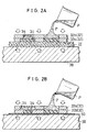
- Fig. 2A is a fragmentary vertical sectional view showing an intermediate step in an embodiment of a method for manufacturing a rugged shaped sheet according to the present invention;
- Fig. 2B is a fragmentary vertical sectional view showing an intermediate step in another embodiment of a method for manufacturing a rugged shaped sheet according to the present invention;
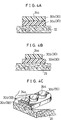
- Figs. 3A to 3C each are a fragmentary vertical sectional view showing an example of a rugged shaped sheet manufactured according to the method shown in Fig. 2A;
- Figs. 4A to 4C each are a fragmentary vertical sectional view showing an example of a rugged shaped sheet manufactured according to the method shown in Fig. 2B;
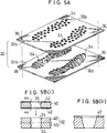
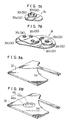
- Fig. 5A is a perspective view showing perforated plates used for manufacturing a rugged shaped sheet of a two-layer structure according to one embodiment of the present invention;
- Fig. 5B (i) is a schematic fragmentary vertical sectional view showing a perforated plate comprising a combination of plural thin plate elements;
- Fig. 5B (ii) is a schematic fragmentary vertical sectional view showing a perforated plate comprising a single thick plate element;
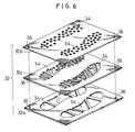
- Fig. 6 is a perspective view showing perforated plates used for manufacturing a rugged shaped sheet of a three-layer structure according to another embodiment of the present invention;
- Figs. 7A and 7B are perspective views showing a rugged pattern in which a difference in area between pattern elements is reduced and a rugged pattern in which the difference is increased, respectively;
- Figs. 8A and 8B each are a fragmentary enlarged perspective view showing a perforated plate having an attracting means provided thereon;
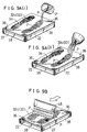
- Figs. 9A (i) and 9A (ii) each are a perspective view showing one example of formation of a base-side pattern element in a process of the present invention in which a base sheet member is previously arranged prior to formation of a rugged pattern;
- Fig. 9B is a perspective view showing a squeegee treatment carried out with respect to the base-side pattern element shown in each of Figs. 9A (i) and 9A (ii);
- Figs. 10A is a perspective view showing one example of formation of a ground-side pattern element in a process of the present invention in which a base sheet member is previously arranged prior to formation of a rugged pattern;
- Fig. 10B is a perspective view showing a squeegee treatment carried out with respect to the ground-side pattern element shown in Fig. 10A;
- Figs. 11A (i) and 11A (ii) each are a perspective view showing another example of formation of a ground-side pattern element in a process of the present invention in which a base sheet member is arranged after formation of a rugged pattern;
- Fig. 11B is a perspective view showing a squeegee treatment carried out with respect to the ground-side pattern element shown in each of Figs. 11A (i) and 11A (ii);
- Fig. 12A is a perspective view showing another example of formation of a base-side pattern element in a process of the present invention in which a base sheet member is arranged after formation of a rugged pattern;
- Fig. 12B is a perspective view showing a squeegee treatment carried out with respect to the base-side pattern element shown in Fig. 12A;
- Figs. 13A and 13B are perspective views showing joining of a rugged pattern to a base sheet member and removal of the rugged pattern from perforated plates, respectively;
- Figs. 14A (i) and 14A (ii) are perspective views showing formation of a base layer and formation of a ground layer which are carried out separately, respectively; and
- Fig. 14B is a perspective view showing joining between the base layer and the ground layer shown in Figs. 14A (i) and 14A (ii).
- Now, the present invention will be described hereinafter with reference to the accompanying drawings.
- The following description on a rugged shaped sheet and a method for manufacturing the same according to the present invention will be made by way of an example of a sole of sports shoes. Also, the description will be made in connection with a rugged shaped sheet, perforated plates used in manufacturing of the rugged shaped sheet, manufacturing of the perforated plates and manufacturing of the rugged shaped sheet in order.
- Referring first to Fig. 1, an example of sports shoes to which an embodiment of a rugged shaped sheet according to the present invention may be applied is illustrated. A rugged shaped sheet of the illustrated embodiment which is generally designated at
reference numeral 20 generally includes abase sheet member 22 and arugged pattern 24 of a predetermined shape arranged in a pattern-like manner on the thebase sheet member 22 while being kept adhered to thebase sheet member 22. Thebase sheet material 22 is cut into a shape in conformity to a sole ofsports shoes 28 and therugged pattern 24 is formed into a predetermined shape so as to provide the sports shoes 28 with non-slip properties. Therugged pattern 24 thus formed is then intimately joined or adhered to thebase sheet member 22, resulting in the rugged shapedsheet 20. - The
base sheet material 22 may be made of any suitable material conventionally used for a base material of an outer sole of sports shoes, such as, for example, a synthetic resin material, a rubber material, a nonwoven fabric material or the like. When a nonwoven fabric material is used for thebase sheet material 22, a thermoplastic fiber material or a thermosetting fiber material may be conveniently directed to this purpose. Foe example, the nonwoven fabric material may include an artificial leather like a back skin which is sold under "ECSAINE" (Registered Trademark) from Toray Kabushiki Kaisha, Japan. The artificial leather may be commercially available in various kinds of colors, therefore, the shoe sole 26 may be provided with a design of any desired color contrast while applying a black color or a color similar thereto to therugged pattern 24. - In addition, any other suitable material such as a conventional nonwoven fabric sheet material having satisfactory peeling or tearing strength, tensile strength and resistance to wear, a film sheet material of an increased thickness, or the like may be conveniently used for this purpose. Further, the material may have adhesive properties or be coated with a resin film. The conventional nonwoven fabric material which is conveniently used may include a nonwoven fabric material having elastic long fibers such as urethane or the like bonded thereto by autohesion. In this instance, application of a nonwoven fabric sheet having a thickness as large as about 1cm permits the sole 26 to be provided with satisfactory cushioning properties. Use of such a film sheet as described above for the
base sheet member 22 causes expression of material contrast between therugged pattern 24 and thebase sheet material 22 as a design to be rendered difficult as compared with the above-described artificial leather or nonwoven fabric material. However, it significantly increases color contrast between both. - Further, when resin cured by ultraviolet rays is used as an elastomer liquid material P (Figs. 2A and 2B) for forming the rugged pattern 3, it is also possible to print a pattern design corresponding to the
rugged pattern 24 on thebase sheet member 22. This permits colors of the pattern design printed on the base sheet material 10 to be visually observed by forming the rugged pattern of a transparent or semitransparent material, resulting in the shoe sole being provided with aesthetic properties different from the above. - Also, various kinds of color contrast may be selected between the
base sheet material 22 and the pattern design printed on the base sheet material. For example, black is employed for thebase sheet member 22, whereas a bright color such as yellow, an orange color or the like is employed for ink printed on thebase sheet member 22. Alternatively, employment of colors which are different in chroma, brightness, hue or any combination thereof for thebase sheet member 22 and the ink for the pattern design printed on thebase sheet member 22 may permit the color of the ink to be prominent relative to the color of thebase sheet member 22 in color contrast between both. For example, red and blue may be employed for thebase sheet member 22 and the ink for this purpose, respectively. - Now, the
rugged pattern 24 will be more detailedly described hereinafter. - The
rugged pattern 24 constitutes one of features of the present invention. Therugged pattern 24 is constructed into a multi-layer structure by laminatedly combining a plurality ofpattern elements 30 formed so as to be different in at least one of a size, a configuration and properties thereof. When it is required to distinguish suchplural pattern elements 30 from each other for the sake of description of the present invention, a pattern element directly tightly joined to thebase sheet member 22 and an uppermost pattern element will be indicated to be a base-side pattern element 30a and a ground-side pattern element 30b, respectively. - The number of layers of the
rugged pattern 24 formed by thepattern elements 30 is at least two. When the number of layers is selected to be two, therugged pattern 24 is constituted by the base-side pattern element 30a and ground-side pattern element 30b described above. Also, when therugged pattern 24 comprises threesuch pattern elements 30, theelements 30 are the above-described base-side pattern element 30a and ground-side pattern element 30b, as well as oneintermediate pattern element 30c interposedly located between thepattern elements rugged pattern 24 is four or more, two or more suchintermediate pattern elements 30c are arranged between the base-side pattern element 30a and the ground-side pattern element 30b. - Now, supposing that the number of layers of the
rugged pattern 24 is two, therugged pattern 24 will be described hereinafter with reference to Figs. 2A to 4C. Figs. 3A to 3C each show arugged pattern 24 manufactured according to a first procedure in Fig. 2A wherein abase sheet member 22 is previously arranged and then perforatedplates 32 are laminated on thebase sheet member 22 in turn. The first procedure causes a squeegee-treated surface to appear on the side of a surface of therugged pattern 24 which is contacted with the ground (hereinafter referred to as "ground surface"). The ground surface is designated atreference character 24a. Therefore, theground surface 24a is formed into a gentle concave shape, so that an outer periphery of theground surface 24a upwardly somewhat projects at an acute angle along a side surface of the pattern as shown in Figs. 3A to 3C. Such configuration of therugged pattern 24 permits it to exhibit increased ground catching properties and non-slip properties. Figs. 4A to 4C each show arugged pattern 24 manufactured according to a second procedure shown in Fig. 2B whereinperforated plates 32 are laminated on each other in turn and then abase sheet member 22 is set. The second procedure causes a squeegee-treated surface to appear at a joint area between pattern elements or at a joint area between the rugged pattern and thebase sheet member 22. Therefore, aground surface 24a is rendered flat as shown in Figs. 4 A to 4 C . Nevertheless, arrangement of a breathable or air-permeable sheet 40 as described hereinafter permits the ground surface to be prevented from being contacted with the air, resulting in unnecessary luster which deteriorates texture of the sole 26 being effectively eliminated. - The
rugged patterns 24 of Figs. 3A to 3C prepared in the manner shown in Fig. 2A each are constructed bypattern elements 30 different in at least one of size, configuration and/or properties from each other, respectively. Also, thepattern elements 30 constituting each of therugged patterns 24 of Figs. 4A to 4C manufactured as shown in Figs. 2B are formed so as to be likewise different in size, configuration and/or properties from each other, respectively. More particularly, in each of therugged patterns 24 shown in Figs. 3A and 4A, thepattern elements side pattern element 30a is rendered somewhat deep as compared with that of the ground-side pattern element 30b. - Arrangement of colors of the
pattern elements 30 is not limited to the above-described manner, so long as colors of thepattern elements 30 vertically laminated on each other are rendered different from each other. Therefore, when three or moresuch pattern elements 30 are provided, two kinds of colors different in hue, brightness and/or chroma may be alternately arranged to provide the pattern elements with a stripe-like design. Further, it is possible to render the pattern elements colorless or colored and transparent. Alternatively, a fluorescent color may be mixed with or substituted for the above-described colors of thepattern elements 30. - The properties of the
pattern elements 30 which may be rendered different between thepattern elements 30 may include hardness, elasticity, a shock absorbing capability, luster, satinizing and the like. - The
pattern elements 30 constituting each of therugged patterns 24 of Figs. 3B and 4B respectively manufactured as shown in Figs. 2A and 2B are formed into sizes which are gradually decreased in turn, so that therugged pattern 24 is formed in a stepwise manner. A manner in which a size of thepattern elements 30 is varied is not limited to the above so long as theperforated plates 32 can be removed from thepattern elements 30. - The
pattern elements 30 constituting each of therugged patterns 24 of Figs. 3C and 4C respectively manufactured as shown in Figs. 2A and 2B are formed so as to be different in configuration as well as size from each other. More particularly, in thepattern elements 30 shown in each of Figs. 3C and 4C, the base-side pattern element 30a is formed into an elliptic shape in plane and the ground-side pattern element 30b is formed into a circular shape in plane and laminatedly arranged on the base-side pattern element 30a. A combination of size and configuration of thepattern elements 30 is not limited to the above. For example, such properties of thepattern elements 40 as shown in Figs. 3A and 4A may be incorporated in the pattern elements shown in Figs. 3C and 4C, so that therugged pattern 24 may be widely varied in various ways. Materials for therugged pattern 24 will be detailedly described hereinafter. - Now, construction and preparation of the
perforated plates 32 used for manufacturing the rugged shapedsheet 20 of the present invention constructed as described above will be described hereinafter. - The
perforated plates 32 used in the present invention each are formed into a somewhat small thickness. This is for the reason that a plurality of theperforated plates 32 are laminatedly used for manufacturing the rugged shaped sheet; therefore, it is required to reduce a thickness of the perforated plates in view of a relationship between a height of therugged pattern 24 and the number ofperforated plates 32 and a variation in attraction force between theperforated plates 32 depending on the size and/or configuration of therugged patterns 24 and a procedure for forming therugged pattern 24. For example, supposing that two suchperforated plates 32 are used to form therugged pattern 24 of a two-layer structure comprising the base-side pattern element 30a and ground-side pattern element 30b, such a thickness of each of the perforated plates 25 as shown in Table 1 may be employed. In Table 1, the designation "Pre-arrangement of Base Sheet Member" indicates that thebase sheet member 22 is previously arranged and then theperforated plates 32 are laminated on thebase sheet member 22 in order. Likewise, the designation "Post-arrangement of Base Sheet Member" indicates that theperforated plates 32 are laminated on each other and then thebase sheet member 22 is arranged. The designations are used in the same meanings throughout the specification. Therefore, the pre-arrangement of thebase sheet member 22 corresponds to the procedure shown in Figs. 2A and the post-arrangement of thebase sheet member 22 corresponds to the procedure shown in Fig. 2B. - Also, in Table 1, the designation "Upper Plate" indicates the perforated plate which is positioned on an upper side in each of the procedures shown in Figs. 2A and 2B and the designation "Lower Plate" indicates the perforated plate positioned on the lower side. Therefore, in the pre-arrangement of the base sheet member shown in Fig. 2A, "Upper Plate" constitutes a ground-side
perforated plate 32b for forming the ground-side pattern element 30b and "Lower Plate" constitutes a base-side perforatedplate 32a for forming the base-side pattern element 30a; whereas, in the post-arrangement of the base sheet member shown in Fig. 2B, "Upper Plate" constitutes the base-side perforated plate and "Lower Plate" constitutes the ground-side perforated plate.Table 1 Perforated Plate Pre-arrangement of Base Sheet Member Post-arrangement of Base Sheet Member Upper Plate 2.0mm 1.6mm Lower Plate 1.3mm 1.4mm - Thus, the base-side and ground-side perforated
plate perforated plates 32, as shown in Fig. 5A, each are formed withperforations 34 of a predetermined shape in a predetermined pattern-like manner in conformity to a configuration of therugged pattern 24 to be formed and its layout. In general, it is required that a position of theperforations 34 is defined so as to be common to all theperforated plates 32. However, a size of the perforations of each perforated plate and a configuration thereof are determined depending on thecorresponding pattern element 30 to be formed. In the illustrated embodiment, a plurality ofperforated plates 32 are arranged while being kept tightly contacted with each other, so that it is advantageous to increase a contact area between theperforated plates 32 as large as possible. Therefore, in the illustrated embodiment, such arugged pattern 24 as shown in Fig. 7A which is constructed so as to reduce a difference in area betweenpattern elements 30 is desirable as compared with arugged pattern 24 as shown in Fig. 7B which is constructed so as to cause a difference in area betweenpattern elements 30 to be rendered relatively large. - Also, a plurality of the
perforated plates 32 are used in the illustrated embodiment, therefore, it is convenient to provide each of the perforated plates with at least oneguide hole 36. Also, it is preferable to employ any means for enhancing adhesion or tightness between theperforated plates 32. - Now, formation of adhesion between the perforated plates by means of magnetic force will be described hereinafter. Such formation of adhesion between the
perforated plates 32 using magnetic force is carried out by providing one of a base 38 or theperforated plates 32 with magnetic force. First, the former case that magnetic force is provided on the side of the base 38 will be described. This is particularly convenient for practicing of the illustrated embodiment. - The base 38 may comprise, for example, an electromagnetic chuck which is conventionally widely used as a workpiece holding means in a surface grinding machine. The
perforated plates 32 to be magnetically sucked by the base 38 each may comprise a relatively thin iron plate of such a thickness as described above. Alternatively, the base may comprise a permanent magnetic chuck, a permanent magnet or the like which exhibits a function similar to the electromagnetic chuck. - As techniques for forming the
perforated plate 32 with theperforations 34 may be used, for example, etching. In this instance, as shown in Fig. 5B (i), a plurality ofthin plate elements 40 which are blank materials for each of theperforated plates 32 are subject to etching, to thereby be-formed withperforations 34 in such a manner that a configuration of the perforations and a pattern thereof are common to theplate elements 40 for eachperforated plate 32. Theplate elements 40 thus formed with thecommon perforations 34 are laminated on each other as shown in Fig. 5B (i) to provide eachperforated plate 32. - More particularly, when the
perforate plate 32 of, for example, 1.6mm in thickness is to be formed, twothin plate elements 40 each having a thickness of 0.8mm are provided. Then, each of theplate elements 40 is covered on each of upper and lower surfaces thereof with aprotection film 42 formed with guide holes 44 and then both surfaces of theplate element 40 are subject to an etching treatment, to thereby be formed with theperforations 34. Then, adhesive such as epoxy adhesive or the like which is capable of forming a rigid adhesive layer is applied between theplate elements 40 to laminatedly join theplate elements 40 to each other, to thereby provide theperforated plate 32. - Such preparation of the
perforated plate 32 from a plurality of thethin plate elements 40 permits a draft of the perforated plate formed to be substantially decreased as compared with a single thick plate element of which one surface is subject to etching as shown in Fig. 5B (ii). An experiment made by the inventors indicated that subjecting of both sides or surfaces of theplate element 40 to etching reduces the draft by half as compared with subjecting of only one surface of theplate element 40 to etching. Also, the draft is reduced with a decrease in thickness of theplate element 40. Such reduction of the draft facilitates introduction of the elastomer liquid material P into theperforations 34 of theperforated plate 32 and removal of theperforated plates 32 from thepattern elements 30 thus formed. - Also, subjecting of both surfaces of the
plate element 40 to etching permits a period of time required for the etching to be reduced as compared with subjecting of only one surface of theplate element 40 to etching. In addition, use of thethin plate elements 40 eliminates a necessity of increasing accuracy with which the guide holes 44 are formed at theprotection film 42. Thus, a period of time and a cost required for preparing theprotection film 42 are significantly reduced. - Further, the above-described etching treatment reduces residual stress in the plate element as compared with a mechanical cutting treatment, to thereby minimize deformation of the
plate elements 40 and therefore therugged pattern 24 due to residual stress. This results in adhesion between the plate elements and/or between the perforated plates and the base 38 being improved, to thereby prevent leakage of the elastomer liquid material P. - Moreover, adhesion between the
thin plate elements 40 by means of the adhesive for providing theperforated plate 32 permits rigidity of the perforated plate 52 thus formed to be increased as compared with the case that the perforated plate is formed of a single thick plate. Alternatively, formation of theperforations 34 may be carried out according to a procedure of using a master mold which is disclosed in Japanese Patent Application Laid-Open Publication No. 307574/1992, Japanese Patent Application Laid-Open Publication No. 343146/1992 and the like by the assignee, a procedure of employing a photo-setting resin film and a sandblasting method. Also, a method of treating a metal or plastic sheet by wire cutting, laser, punching, pressing or the like may be applied for this purpose. - Further, the illustrated embodiment may be constructed in such a manner that the
perforated plates 32 laminated on each other are rendered different in magnetic characteristics, to thereby balance magnetic characteristics between the perforated plates. For example, this is carried out by arranging theperforated plates 32 so as to reduce magnetic characteristics of the perforated plate(s) on the side of thebase sheet member 22 in turn and maximize magnetic characteristics of the uppermostperforated plate 32. - Now, the latter case that magnetic force is provided on the side of the
perforated plates 32 will be described. In this instance, as thebase 38 may be used a plate-like or block-like magnetic member which is made of, for example, a metal material such as iron or the like. Theperforated plates 32 each may be constructed as shown in Fig. 8A or 8B. Fig. 8A shows theperforated plate 32 which is made of a permanent magnet. For this purpose, a plastic magnet may be conveniently used because of being readily shaped and suitable for mass-production. The plastic magnet is made of a mixture of a thermosetting or thermoplastic resin material and a magnetic power material such as ferrite or the like added to the resin material. Preferably, it is a rare earth type plastic magnet made by molding a mixture of a plastic material and a samarium-cobalt magnetic power material which is capable of effectively preventing its magnetic characteristics from being extensively deteriorated even when it is shaped in the form of a thin plate. - It would be considered that use of such a resin material for the
perforated plate 32 causes the resin material and elastomer liquid material to be adhered together due to affinity therebetween. Therefore, any means of ensuring satisfactory removal of theperforated plate 32 from thepattern element 30 may be required. The means includes a decrease in thickness of theperforated plate 32, use of a parting agent and the like. - Fig. 8B shows the
perforated plate 32 which is provided at a portion thereof free of theperforations 34 with a magnetic attracting means 46. The magnetic attracting means 46 comprises apermanent magnet 46a and anon-magnetic ring 46b made of a non-magnetic material such as brass or the like and arranged so as to surround thepermanent magnet 46a. Such arrangement of the magnetic attracting means 46 interrupts horizontal magnetic characteristics of thepermanent magnet 46a which affect theperforated plate 32, so that the characteristics may be used for tightly joining the perforated plate to the perforated plate vertically adjacent thereto. - Thus, the construction shown in Fig. 8B enhances the magnetic characteristics of the attracting means 46. The permanent magnet may comprise a plastic magnet, a sintered magnet made of alnico alloy or ferrite, or the like.
- Alternatively, adhesion between the
perforated plates 32 may be carried out by spraying water between the perforated plates and then freezing it to join the perforated plates together. Also, a procedure of applying droplets of water or temporary liquid adhesive between the perforated plates or any mechanical adhesion means may be employed for this purpose. Moreover, the illustrated embodiment may be so constructed that thebase sheet member 22 is interposedly arranged between the base-side perforatedplate 32a and the base 38 constituted by a permanent magnet, to thereby be magnetically held therebetween. Such construction requires to carry magnetic metal on at least a surface of theperforated plate 32. - Now, preparation of the rugged shaped sheet of the present invention will be described in connection with both the pre-arrangement of the base sheet member and the post-arrangement of the base sheet member with reference to Figs. 9A (i) to 10B and Figs. 11A (i) to 13B.
- First, setting of the base-side perforated
plate 32a will be described with reference to Figs. 2A and 9A. Thebase sheet member 22 is put on thebase 38 and then the base-side perforatedplate 32a for forming the base-side pattern element 30a is arranged on thebase sheet member 22 and tightly joined to thebase sheet member 22. - Then, the elastomer liquid material P for forming the
rugged pattern 24 is poured into theperforations 34 of theperforated plate 32a as shown in Fig. 9A (i). When a polyurethane elastomer is used as the elastomer liquid material P, two liquids constituting the material P are mixed together in a vessel to carry out deaeration prior to the pouring as shown in Fig. 9A (i). Also, the two liquids may be mixed in a cylinder by means of a static mixer widely used in an industrial scale and injected into the perforations through a nozzle. Alternatively, as shown in Fig. 9A (ii), the two liquids for the elastomer liquid material P may be sprayed toward theperforations 34 of theperforated plate 32 through nozzles while being mixed together. - The polyurethane elastomer may comprise a mixture of a prepolymer and polyisocyanate and is cured by heating. A polyurethane elastomer which is suitable for spraying through a nozzle includes a non-solvent fast-curing urethane resin material commercially available from Nippon Gosei kagaku Kogyo Kabushiki Kaisha, Japan. The resin material is preferably kept heated prior to the spraying. This results in the material being cured in a gel time as short as 20 seconds. Also, the elastomer liquid material P may be added thereto a solvent for adjusting viscosity of the material, its hardness or the like. The polyurethane elastomer may further include a mixture of a prepolymer commercially available under a tradename "Nipporan" from Nippon Polyurethane Kogyo Kabushiki kaisha, Japan and polyisocyanate commercially available under a tradename "Pandex" from Dai-Nippon Ink Kabushiki Kaisha.
- It may be required to prevent the elastomer liquid material P from flowing out of the
perforated plate 32. For this purpose, it is preferable to incorporate a thickening agent in the material. Such a thickening agent includes, for example, a thickening agent manufactured by Nippon Aerosil Kabushiki Kaisha and sold under "AEROSIL" (registered trademark). The agent comprises silica (SiO₂) of a high purity (99.8%) and in the form of ultrafine particles of 7 to 50µm. Also, it has a large surface area and high dispersion properties and is harmless. Addition of the thickening agent in a small amount permits rheological characteristics to be exhibited to a degree sufficient to be required for processing of a liquid material such as a polyester resin material, an epoxy resin material or the like. It is a matter of course that another filler material may be added to the elastomer liquid material P. - A photo-setting resin material may be used as the elastomer liquid material P as well. Now, the photo-setting resin will be described by way of an ultraviolet-setting resin material which is adapted to be cured for a short period of time by irradiation of ultraviolet rays.
- An ultraviolet-setting resin material used for the present invention is desirably transparent or semitransparent both before and after curing so that ultraviolet rays may reach a bottom of the
perforations 34 or the base-side pattern element 30a and a color of a pattern printed on thebase sheet member 22 may be observed through theother pattern elements rugged pattern 24 is used for the shoe sole 26 in the illustrated embodiment; therefore, it is preferable that the ultraviolet-setting resin material used permits therugged pattern 24 to exhibit satisfactory physical properties required for the shoe sole 26, such as, for example, elasticity, tensile strength, tearing strength, resistance to wear and the like. An increase in tearing strength may be carried out by adding a filler such as short fibers or the like to the ultraviolet-setting resin material in an amount which does not cause deterioration of curing of the resin. - After a predetermined amount of elastomer liquid material P is poured into the
perforations 34 of the perforated plate 32 (32a) as described above, asqueegee 48 is used to remove a portion of the elastomer liquid material P overflowing theperforations 34 as shown in Fig. 9B. Simultaneously, another portion of the liquid material P existing right under an upper surface of the perforations is removed while being dragged by a distal end of thesqueegee 48, in view of surface tension of the liquid material, a contact angle between the liquid material P and theperforations 34 of theperforated plate 32 or the distal end of thesqueegee 48, wetting of thesqueegee 48, or the like. - At the time when the elastomer liquid material P thus charged in the
perforations 34 of the perforated plate 32 (32a) is semicured to a degree sufficient to permit the perforated plate to be somewhat released or removed from the liquid material P and prevent peeling or separation between thepattern elements 30 to be joined together, the ground-sideperforated plate 32b is arranged on the base-side perforatedplate 32a. Then, pouring of the elastomer liquid material P and the squeegee treatment described above are carried out with respect to theperforated plate 32b and thereafter the elastomer liquid material is cured to a degree sufficient to prevent such separation as described above between thepattern elements 30. - The squeegee treatment permits an upper surface of the elastomer liquid material P to be formed into a concave shape. Formation of such a concave shape is accomplished without any specific squeegee and/or squeegeeing procedure. For example, this may be readily attained by politely carrying out a conventional squeegee treatment using the elastomer liquid material P and
squeegee 48 described above. Also, a degree of depression formed on the upper surface of the elastomer liquid material P depends on factors such as surface tension of the liquid material, a contact angle between the liquid material P and theperforations 34 of theperforated plate 32 or the distal end of thesqueegee 48, wetting of thesqueegee 48 or the like, rather than squeegeeing techniques employed. Therefore, determination of such factors affects the depression. A surface of the pattern element which has been subject to the squeegee treatment constitutes the above-describedground surface 24a of therugged pattern 24. - When the elastomer liquid material P poured into the
perforations 34 of theperforated plates 32 is semicured as described above, removal of the perforated plates is carried out from the ground-sideperforated plate 32b to the base-side perforatedplate 32a in order. Then, the elastomer liquid material P is completely cured, resulting in the rugged shapedsheet 20 as shown in Fig. 1 being formed wherein therugged pattern 24 of a multi-layer structure is arranged on thebase sheet member 22. - First, setting or arrangement of an air-
permeable sheet 50 on thebase 38 will be described with reference to Fig. 2A. The breathable or air-permeable sheet 50 is merely required to function to exhibit air permeability sufficient to permit air which entered theperforations 34 of theperforated plate 32 to be outwardly discharged from theperforations 34. Therefore, the air-permeable sheet 50 may be constructed so as to permit air to pass through a tissue of thesheet 50. Alternatively, it may be so constructed that air is kept remaining in recesses on a surface of thesheet 50 or cavities in the tissue of thesheet 50. - The air-
permeable sheet 50 may be formed of a continuous air-permeable material such as a nonwoven fabric material, a sponge material, a frosted film such as a polyethylene film formed thereon with unevenness for eliminating luster or the like, as well as a film subject to fine embossing or the like. Use of the continuous air-permeable material such as a nonwoven fabric material, a sponge material or the like for the air-permeable sheet 50 permits air entering theperforations 34 of theperforated plate 32 to be outwardly discharged through the air-permeable sheet 50 and/or enter the cavities within the tissue of the air-permeable sheet 50; whereas use of the frosted film or the film subject to fine embossing for thesheet 50 permits the air to enter in the recesses formed on the surface of the air-permeable sheet 50, to thereby promote outward discharge of the air. Also, when the air-permeable sheet 50 is tightly contacted with theperforated plate 32, a parting agent is used to facilitate releasing of the air-permeable sheet 50 from the elastomer liquid material P and theperforated plate 32. Alternatively, the air-permeable sheet 50 may be made of a material which exhibits release characteristics, to thereby eliminate use of the parting agent. - Alternatively, the
perforated plate 32 may be arranged directly on thebase 38 without interposing the air-permeable sheet 50 therebetween. In this instance, it is convenient that a parting agent is previously applied to the base 38 in order to facilitate release of the base 38 from the elastomer liquid material P. - Then, the ground-side
perforated plate 32b is arranged or set on an upper surface of the air-permeable sheet 50 or an upper surface of the base 38 to which the parting agent is applied. Thereafter, the elastomer liquid material P is poured into theperforations 34 of the ground-sideperforated plate 32b as in "1. Pre-arrangement of Base Sheet Member" described above. when a polyurethane elastomer is used as the elastomer liquid material P, two liquids constituting the elastomer liquid material P are mixed in a vessel to carry out defoaming prior to the pouring as shown in Fig. 11A (i). Also, the two liquids may be mixed in a cylinder by means of a static mixer widely used in an industrial scale and injected into the perforations through a nozzle. Alternatively, as shown in Fig. 11A (ii), the two liquids for the elastomer liquid material P may be sprayed toward theperforations 34 through nozzles while being mixed together. - After a predetermined amount of elastomer liquid material P is poured into the
perforations 32 of theperforated plate 32b as described above, asqueegee 48 is used to remove a portion of the elastomer liquid material P overflowing theperforations 34 as shown in Fig. 11B. - Then, at the time when the elastomer liquid material P thus charged in the
perforations 34 of the perforated plate 32 (32a) is semicured as in "1. Pre-arrangement of Base Sheet Member" described above, the ground-sideperforated plate 32b is arranged or set on the base-side perforatedplate 32a. Subsequently, poring of the elastomer liquid material P and a squeegee treatment are carried out in a manner like the above. - After the pouring and squeegee treatment of the elastomer liquid material P are carried out as described above, the
base sheet member 22 is set on an upper surface of the base-side perforatedplate 32a. Then, a weight W is put on thebase sheet member 22 to press themember 22, to thereby adhere thebase sheet member 22 to the base-side perforatedplate 32a and cure the elastomer liquid material P in theperforations 34 of the perforated plate to a degree sufficient to permit removal of the perforated plate. Then, the weight W is upwardly removed and thebase sheet member 22 is drawn up to fully cure the elastomer liquid material P as shown in Fig. 13B, resulting in such a rugged shapedsheet 20 as shown in Fig. 1 being prepared. Such a procedure minimizes or prevents deterioration of contrast between the ground-side pattern element 30a and the ground-side pattern element 30b due to squeeze-out of the base-side pattern element 30a. The above-described pressing of the base sheet member may be carried out using a press unit in place of the weight W, to thereby promote pressing of thebase sheet member 22 against therugged pattern 24. - The following procedure may be employed as an intermediate procedure between "1. Pre-arrangement of Base Sheet Member" and "2. Post-arrangement of Base Sheet member" described above.
- As shown in Figs. 14A (i) to 14B, two
bases 38 are prepared. On one of thebases 20 is set thebase sheet member 22 as in "1. Pre-arrangement of Base Sheet Member" described above, and then the base-side perforatedplate 32a is set on thebase sheet member 22. Subsequently, the elastomer liquid material P is poured into theperforations 34 of the base-side perforatedplate 32a and then a portion of the liquid material P overflowing theperforations 34 is removed by means of asqueegee 48, to thereby form a base layer as shown in Fig. 14A (i). - On the
other base 38 is set the air-permeable sheet 50 as "2. Post-arrangement of Base Sheet member" described above and then the ground-sideperforated plate 32b is arranged on the air-permeable sheet 50. Alternatiyely, when theperforated plate 32 is directly arranged on thebase 38 without using the air-permeable sheet 50, a parting agent is applied to thebase 38. Then, the ground-sideperforated plate 32b is arranged on thebase 38. Thereafter, the elastomer liquid material P is poured into theperforations 34 of the ground-sideperforated plate 32b and then a portion of the liquid material P overflowing theperforations 34 is removed by means of asqueegee 48, to thereby form a ground layer as shown in Fig. 14A (ii). - Subsequently, at the time when the elastomer liquid material P for each of the base layer and ground layer is semicured, the ground layer is arranged on the base layer and a pressure is downwardly applied to a combination of the base layer and ground layer to cure the elastomer liquid material P to a degree sufficient to permit removal of the perforated plates.
- Then, the ground-side
perforated plate 32b and base-side perforatedplate 32a are removed in turn, to thereby fully cure the elastomer, resulting in such a rugged shapedsheet 20 as shown in Fig. 20 being prepared. - The intermediate procedure described above permits the base layer and ground layer to be concurrently formed, to thereby contribute to an increase in productivity.
- Formation of an intermediate layer by means of the intermediate
perforated plate 32c may be carried out by arranging the intermediate between the base-side perforatedplate 32a and the ground-sideperforated plate 32b and the elastomer liquid material P is poured into theperforations 34 of the intermediateperforated plate 32c, followed by a squeegee treatment, to thereby form the intermediate layer. - Application of the
rugged shapes sheet 20 of the present invention is not limited to a sole of sports shoes. For example, it may be effectively applied to stripes for design or reinforcement provided on an upper part of sports shoes; a grip for a bicycle, a tennis racket and a badminton racket; a saddle for a bicycle; a non-slip member for a snow board and a surfboard; a glove for athletics or sports such as baseball, soccer and bicycle racing; a grip for various kinds of tools; a grip for a camera and a video camera; and the like. - As can be seen from the foregoing, the rugged shaped sheet of the present invention is so constructed that the rugged pattern is constituted by the plural pattern elements which are formed so as to be different in at least one of size, configuration and properties from each other, resulting in being constructed into a multi-layer structure. Such construction permits the rugged pattern to be provided thereon with a strip-or stripe-like color design when different colors are applied to the pattern elements, respectively, to thereby improve aesthetic properties of the rugged shaped sheet. Also, when the pattern elements of the rugged pattern are formed so as to be different in size or combination of size and configuration from each other, resulting in the rugged pattern being formed into a stepwise configuration, the rugged pattern may be formed into a more complicated configuration sufficient to further improve the aesthetic properties.
- Also, in the process of the present invention, the rugged pattern is successively formed from the base side or ground side, so that the properties, size and/or configuration of the pattern elements may be varied as required, resulting in the rugged shaped sheet of a complicated configuration required to provide non-slip properties being manufactured with ease and at a reduced cost.
- While a preferred embodiment of the invention has been described with a certain degree of particularity with reference to the drawings, obvious modifications and variations are possible in light of the above teachings. It is therefore to be understood that within the scope of the appended claims, the invention may be practiced otherwise than as specifically described.
Claims (13)
- A rugged shaped sheet (20) comprising:
a base sheet member (22); and
a rugged pattern (24) of a predetermined shape adhered to said base sheet member;
said rugged pattern comprising a combination of a plurality of pattern elements (30) which are formed so as to be different in at least one of size, configuration and properties from each other. - A rugged shaped sheet (20) as defined in Claim 1, characterized in that said rugged shaped sheet (20) constitutes an outer sole which forms a lowermost layer of a shoe sole.
- A rugged shaped sheet (20) as defined in Claim 1 or 2, characterized in that said rugged pattern (24) has a ground surface generally formed into a concave shape;
said ground surface having a periphery formed at an acute angle with respect to a side surface of said rugged pattern. - A rugged shaped sheet (20) as defined in any one of Claims 1 to 3, characterized in that said pattern elements (30) of said rugged pattern (24) have colors applied thereto in such a manner that said colors are different between each two of said pattern elements which are arranged so as to be adjacent to each other in at least a vertical direction.
- A rugged shaped sheet (20) as defined in any one of Claims 1 to 4, characterized in that said pattern elements (30) of said rugged pattern (24) are formed so as to be different in size or combination of size and configuration from each other, resulting in said rugged pattern being formed into a stepwise configuration.
- A process for manufacturing a rugged shaped sheet (20) comprising the steps of:
arranging a base sheet member (22) on a base (38);
arranging, on the base sheet member, perforated plates (32) formed with perforations (34) of a predetermined shape in a pattern-like manner;
pouring an elastomer liquid material (P) into the perforations of each of the perforated plates;
subjecting the elastomer liquid material to a squeegee treatment; and
curing the elastomer liquid material,
characterized in that:
at least two such perforated plates (32) including a base-side perforated plate (32a) and a ground-side perforated plate (32b) each formed with said perforations (34) are provided;
the base-side perforated plate (32a) is first arranged on the base sheet member (22);
the elastomer liquid (P) is poured in a predetermined amount into the perforation of the base-side perforated plate, subjected to the squeegee treatment and then semicured, resulting in forming a base layer;
the ground-side perforated plate (32b) is arranged on the base layer thus formed;
the elastomer liquid material (P) is poured in a predetermined amount into the perforations (34) of the ground-side perforated plate (32b), subjected to the squeegee treatment and cured to a degree sufficient to permit the elastomer liquid material to be removed from the ground-side perforated plate, resulting in forming a ground layer;
the perforated plates (32) are removed from the cured elastomer liquid material (P) in turn subsequent to formation of the ground layer, to thereby obtain a combination of the base sheet member (22) and a rugged pattern (24) of a predetermined configuration adhesively formed on the base sheet member; and
the combination is fully cured to form the rugged shaped sheet (20). - A process as defined in Claim 6, characterized in that said perforated plates (32) further includes at least one intermediate perforated plate (32c) likewise formed with perforations (34);
the intermediate perforated plate is arranged on the base layer after formation of the base layer;
the elastomer liquid material (P) is poured into the perforations of the intermediate perforated plate, subjected to a squeegee treatment and semicured, resulting in forming an intermediate layer;
the elastomer liquid material (P) is poured into, if present, at least one additional intermediate perforated plate (32c), subjected tothe squeegee treatment and then semicured, to thereby form at least one intermediate layer; and
the ground-side perforated plate (32b) is put on the intermediate layer thus formed, to thereby form the ground layer. - A process for manufacturing a rugged shaped sheet comprising the steps of:
arranging, on a base (38), perforated plates (32) formed with perforations (34) of a predetermined shape in a pattern-like manner;
pouring an elastomer liquid material (P) into the perforations of each of the perforated plates, followed by a squeegee treatment;
arranging a base sheet member (22) on the perforated plates and holding the former on the latter while downwardly pressing, leading to curing of the elastomer liquid material;
characterized in that:
the perforated plates (32) include at least a base-side perforated plate (32a) and a ground-side perforated plate (32b);
the ground-side perforated plate is first arranged on an air-permeable sheet (50) and charged with the elastomer liquid material in a predetermined amount;
the elastomer liquid material (P) poured in the ground-side perforated plate is subjected to the squeegee treatment and then semicured, leading to formation of a ground layer; and
a base layer is laminated on the ground layer. - A process as defined in Claim 8, characterized in that arrangement of the ground-side perforated plate (32b) on the base (38) is carried out by arranging the air-permeable sheet (50) on the base, arranging the ground-side perforated plate on the air-permeable sheet after, if necessary, application of a parting agent to the base, and then arranging the ground-side perforated plate on the base.
- A process as defined in Claim 8 or 9, characterized in that lamination of the base layer on the ground layer is carried out by arranging the base-side perforated plate (32a) on the ground layer at the time when the ground layer is formed and arranging the base sheet member (22) on the base layer at the time when the elastomer liquid material (P) is semicured to form the base layer.
- A process as defined in Claim 8 or 9, characterized in that lamination of the base layer on the ground layer further includes arrangement of an intermediate product formed by laminating an additional base layer on an additional base sheet member (22) in a different step on the ground layer at the time when the ground layer is formed.
- A process as defined in any one Claims 8 to 11, characterized in that the perforated plates (32) further include at least one intermediate perforated plate likewise formed with perforations;
the intermediate perforated plate (32c) is arranged on the ground layer after formation of the ground layer;
the elastomer liquid material (P) is poured into the perforations of the intermediate perforated plate, subjected to a squeegee treatment and semicured, resulting in forming an intermediate layer; and
the base-side perforated plate (32a) is arranged on the intermediate layer thus formed, to thereby form the ground layer. - A process as defined in any one of Claims 6 to 12, characterized in that the perforations (34) of each of the perforated plates (32) are formed by etching.
Applications Claiming Priority (15)
| Application Number | Priority Date | Filing Date | Title |
|---|---|---|---|
| JP18592392 | 1992-06-19 | ||
| JP18592392 | 1992-06-19 | ||
| JP185923/92 | 1992-06-19 | ||
| JP30757492 | 1992-10-21 | ||
| JP30757492A JP3218413B2 (en) | 1992-06-19 | 1992-10-21 | Manufacturing method of embossed sheet |
| JP307574/92 | 1992-10-21 | ||
| JP351902/92 | 1992-12-09 | ||
| JP35190292A JP3239192B2 (en) | 1992-12-09 | 1992-12-09 | Manufacturing method of special shape emboss |
| JP35190292 | 1992-12-09 | ||
| JP6284393 | 1993-02-26 | ||
| JP62843/93 | 1993-02-26 | ||
| JP6284393A JP3326506B2 (en) | 1993-02-26 | 1993-02-26 | Manufacturing method of uneven molded sheet |
| JP16611093A JP3243699B2 (en) | 1993-06-11 | 1993-06-11 | Manufacturing method of uneven molded sheet |
| JP166110/93 | 1993-06-11 | ||
| JP16611093 | 1993-06-11 |
Publications (2)
| Publication Number | Publication Date |
|---|---|
| EP0577307A1 true EP0577307A1 (en) | 1994-01-05 |
| EP0577307B1 EP0577307B1 (en) | 1999-09-29 |
Family
ID=27523736
Family Applications (1)
| Application Number | Title | Priority Date | Filing Date |
|---|---|---|---|
| EP93304830A Expired - Lifetime EP0577307B1 (en) | 1992-06-19 | 1993-06-21 | Rugged shaped sheet and process for manufacturing same |
Country Status (6)
| Country | Link |
|---|---|
| US (3) | US5389176A (en) |
| EP (1) | EP0577307B1 (en) |
| CN (1) | CN1066620C (en) |
| DE (1) | DE69326581T2 (en) |
| ES (1) | ES2139627T3 (en) |
| SG (1) | SG72668A1 (en) |
Cited By (3)
| Publication number | Priority date | Publication date | Assignee | Title |
|---|---|---|---|---|
| EP0850750A2 (en) * | 1996-10-12 | 1998-07-01 | Robert Bosch Gmbh | Process for producing a microstructured body, a casting frame and an integrated optical object |
| US7047668B2 (en) | 2003-07-24 | 2006-05-23 | Nike, Inc. | Article of footwear having an upper with a polymer layer |
| US20160101583A1 (en) * | 2014-10-09 | 2016-04-14 | Dah Lih Puh Co., Ltd. | Mold and method for making heterogeneous composite outer shoe sole |
Families Citing this family (37)
| Publication number | Priority date | Publication date | Assignee | Title |
|---|---|---|---|---|
| CN1066620C (en) * | 1992-06-19 | 2001-06-06 | 铃木总业株式会社 | Sheet with raised pattern and method of manufacturing the same |
| US5705970A (en) * | 1993-10-15 | 1998-01-06 | Kabushiki Kaisha Sankyo Seiki Seisakusho | Rare-earth containing iron-base resin bonded magnets |
| US6702559B1 (en) * | 1997-12-12 | 2004-03-09 | Jimmy W. Norman | Template for creating designs |
| JP2001213214A (en) * | 2000-02-03 | 2001-08-07 | Eidai Kako Kk | Floor mat for automobile |
| US7018692B2 (en) * | 2000-07-06 | 2006-03-28 | Higher Dimension Medical, Inc. | Penetration resistant fabric with multiple layer guard plate assemblies and method of making the same |
| US6557272B2 (en) * | 2001-07-13 | 2003-05-06 | Luigi Alessio Pavone | Helium movement magnetic mechanism adjustable socket sole |
| JP2003039582A (en) * | 2001-07-19 | 2003-02-13 | Three M Innovative Properties Co | Wet anti-slip sheet and wet anti-slip structure |
| JP4326190B2 (en) * | 2002-07-10 | 2009-09-02 | スリーエム イノベイティブ プロパティズ カンパニー | Flexible mold and manufacturing method thereof |
| US20060099871A1 (en) * | 2004-11-05 | 2006-05-11 | Kimberly-Clark Worldwide, Inc. | Reinforced elastic fiberous web |
| US20060213084A1 (en) * | 2005-03-23 | 2006-09-28 | Scales Cheryl D | Footwear insert and method of producing same |
| CN100471643C (en) * | 2006-09-30 | 2009-03-25 | 立兆股份有限公司 | Production process of forming plastic onto soft cloth |
| US20080081204A1 (en) * | 2006-10-02 | 2008-04-03 | Chien-Kang Ho | Elastic coated fabric and method for manufacturing the same |
| US20110056094A1 (en) * | 2008-03-14 | 2011-03-10 | Yanke Paul H | Magnetic boot attachment for a stirrup |
| US8371046B2 (en) * | 2008-03-14 | 2013-02-12 | Ontyte Llc | Stirrup |
| US20100031535A1 (en) * | 2008-08-05 | 2010-02-11 | Gregory Ross Leedy | Printed sole for a shoe and method of making |
| US8249887B2 (en) * | 2009-09-03 | 2012-08-21 | The Invention Science Fund I, Llc | Personalized plan development based on identification of one or more relevant reported aspects |
| US8772087B2 (en) | 2009-10-22 | 2014-07-08 | Infineon Technologies Ag | Method and apparatus for semiconductor device fabrication using a reconstituted wafer |
| JP6017312B2 (en) | 2009-12-22 | 2016-10-26 | フィッシャー アンド ペイケル ヘルスケア リミテッド | Medical circuit components |
| CN101884444A (en) * | 2010-07-06 | 2010-11-17 | 张健 | Method for manufacturing sole and sole manufactured by same |
| DE102010055818A1 (en) * | 2010-12-23 | 2012-06-28 | Puma Aktiengesellschaft Rudolf Dassler Sport | Shoe, in particular sports shoe, and method for producing a shoe |
| KR20130127655A (en) * | 2012-05-15 | 2013-11-25 | 엘지이노텍 주식회사 | Touch window and manufacturing method thereof |
| US10945488B2 (en) | 2013-08-09 | 2021-03-16 | Reebok International Limited | Article of footwear with extruded components |
| CN106572717B (en) * | 2014-07-11 | 2021-06-29 | 健乐士股份公司 | Method for providing a part of a waterproof and vapor-permeable shoe, part of a waterproof and vapor-permeable shoe provided with said method, and waterproof and vapor-permeable sole provided with said part of a shoe |
| US11019879B2 (en) | 2015-11-18 | 2021-06-01 | Reebok International Limited | Extruded components for articles of footwear and methods of making the same |
| CN108724599A (en) * | 2017-04-18 | 2018-11-02 | 张仲甫 | The massage manufacturing process of resistance to slide plate and its finished product of treadmill |
| CN113729353B (en) * | 2017-04-21 | 2024-03-05 | 耐克创新有限合伙公司 | Sole structure with proprioceptive element and method of manufacturing sole structure |
| US11136475B2 (en) | 2017-04-24 | 2021-10-05 | Nike, Inc. | Articles and components with UV radiation curable elastomeric materials and methods of making the same |
| CN110545976A (en) * | 2017-04-24 | 2019-12-06 | 耐克创新有限合伙公司 | Transparent tooling die and process for UV radiation curable rubber |
| CN110573329B (en) * | 2017-04-24 | 2021-10-22 | 耐克创新有限合伙公司 | Articles and parts having UV radiation curable elastomeric material and methods of making the same |
| EP3599921B1 (en) | 2017-04-24 | 2022-05-25 | NIKE Innovate C.V. | Article with uv radiation curable material adhered to textile and method of making the same |
| WO2018200362A1 (en) | 2017-04-24 | 2018-11-01 | Nike Innovate C.V. | Apparel and sporting equipment with an uv radiation curable material and method of manufacturing thereof |
| US11059249B2 (en) * | 2017-06-19 | 2021-07-13 | Under Armour, Inc. | Footwear and method of formation |
| US10485302B2 (en) | 2017-07-07 | 2019-11-26 | Reebok International Limited | Method of making an upper |
| US11472066B2 (en) * | 2018-06-18 | 2022-10-18 | Crayola Llc | Stackable/nesting stencil or mold system for modeling compound |
| US11278081B2 (en) | 2018-10-10 | 2022-03-22 | Reebok International Limited | Article of footwear with dispensed components |
| DE102018221393A1 (en) * | 2018-12-11 | 2020-06-18 | Rhenoflex Gmbh | Powder application device and method for producing stiffening elements from powdery material |
| WO2023205297A1 (en) * | 2022-04-20 | 2023-10-26 | Navail Emmanuel Benjamin Andre | Magnetic sole and shoe |
Citations (4)
| Publication number | Priority date | Publication date | Assignee | Title |
|---|---|---|---|---|
| BE357280A (en) * | ||||
| FR2323521A1 (en) * | 1975-09-11 | 1977-04-08 | Metzeler Kautschuk | METHOD AND DEVICE FOR MANUFACTURING LAMINATED BODIES, IN PARTICULAR MULTI-LAYER SHOE SOLES |
| US4364190A (en) * | 1980-08-14 | 1982-12-21 | Brs, Inc. | Outer sole for athletic shoe |
| JPH01310601A (en) * | 1988-06-08 | 1989-12-14 | Asics Corp | Production of shoe sole |
Family Cites Families (14)
| Publication number | Priority date | Publication date | Assignee | Title |
|---|---|---|---|---|
| US2264628A (en) * | 1939-08-03 | 1941-12-02 | Poster Products Inc | Advertising material |
| US4183978A (en) * | 1972-03-23 | 1980-01-15 | Kufner Textilwerke Kg | Raster-like coating of heat-sealable adhesives on substrates |
| DE2351405C3 (en) * | 1973-10-12 | 1979-05-17 | Kufner Textilwerke Kg, 8000 Muenchen | Process for the production of a one-sided heat-sealable fleece |
| JPS538569B2 (en) * | 1974-12-28 | 1978-03-30 | ||
| JPS604796B2 (en) * | 1976-12-29 | 1985-02-06 | 大日本印刷株式会社 | Transfer sheet for resist dyeing |
| US4324815A (en) * | 1978-01-24 | 1982-04-13 | Mitani Electronics Industry Corp. | Screen-printing mask and method |
| DE2813958A1 (en) * | 1978-03-31 | 1979-10-04 | Funck Herbert | SHOE SOLE |
| DE3338557A1 (en) * | 1983-10-24 | 1985-05-02 | Puma-Sportschuhfabriken Rudolf Dassler Kg, 8522 Herzogenaurach | SPORTSHOE WITH A SHOCK ABSORBING OUTSOLE AND METHOD FOR PRODUCING SUCH A SPORTSHOE |
| US4986496A (en) * | 1985-05-31 | 1991-01-22 | Minnesota Mining And Manufacturing | Drag reduction article |
| US4676010A (en) * | 1985-06-10 | 1987-06-30 | Quabaug Corporation | Vulcanized composite sole for footwear |
| US4897936A (en) * | 1988-02-16 | 1990-02-06 | Kaepa, Inc. | Shoe sole construction |
| US4991990A (en) * | 1990-01-05 | 1991-02-12 | Minnesota Mining And Manufacturing Company | Photograph album attachment assembly |
| JP2968555B2 (en) * | 1990-05-10 | 1999-10-25 | 理想科学工業株式会社 | Mold making method |
| CN1066620C (en) * | 1992-06-19 | 2001-06-06 | 铃木总业株式会社 | Sheet with raised pattern and method of manufacturing the same |
-
1993
- 1993-06-19 CN CN93109450A patent/CN1066620C/en not_active Expired - Lifetime
- 1993-06-21 EP EP93304830A patent/EP0577307B1/en not_active Expired - Lifetime
- 1993-06-21 DE DE69326581T patent/DE69326581T2/en not_active Expired - Lifetime
- 1993-06-21 SG SG1996008281A patent/SG72668A1/en unknown
- 1993-06-21 US US08/079,376 patent/US5389176A/en not_active Expired - Lifetime
- 1993-06-21 ES ES93304830T patent/ES2139627T3/en not_active Expired - Lifetime
-
1996
- 1996-01-04 US US08/582,897 patent/US5709763A/en not_active Expired - Fee Related
-
1997
- 1997-10-20 US US08/954,095 patent/US5853854A/en not_active Expired - Lifetime
Patent Citations (4)
| Publication number | Priority date | Publication date | Assignee | Title |
|---|---|---|---|---|
| BE357280A (en) * | ||||
| FR2323521A1 (en) * | 1975-09-11 | 1977-04-08 | Metzeler Kautschuk | METHOD AND DEVICE FOR MANUFACTURING LAMINATED BODIES, IN PARTICULAR MULTI-LAYER SHOE SOLES |
| US4364190A (en) * | 1980-08-14 | 1982-12-21 | Brs, Inc. | Outer sole for athletic shoe |
| JPH01310601A (en) * | 1988-06-08 | 1989-12-14 | Asics Corp | Production of shoe sole |
Non-Patent Citations (1)
| Title |
|---|
| PATENT ABSTRACTS OF JAPAN vol. 014, no. 106 (C - 694) 27 February 1990 (1990-02-27) * |
Cited By (5)
| Publication number | Priority date | Publication date | Assignee | Title |
|---|---|---|---|---|
| EP0850750A2 (en) * | 1996-10-12 | 1998-07-01 | Robert Bosch Gmbh | Process for producing a microstructured body, a casting frame and an integrated optical object |
| EP0850750A3 (en) * | 1996-10-12 | 1998-09-30 | Robert Bosch Gmbh | Process for producing a microstructured body, a casting frame and an integrated optical object |
| US7047668B2 (en) | 2003-07-24 | 2006-05-23 | Nike, Inc. | Article of footwear having an upper with a polymer layer |
| US20160101583A1 (en) * | 2014-10-09 | 2016-04-14 | Dah Lih Puh Co., Ltd. | Mold and method for making heterogeneous composite outer shoe sole |
| US9648923B2 (en) * | 2014-10-09 | 2017-05-16 | Dah Lih Puh Co., Ltd. | Mold and method for making heterogeneous composite outer shoe sole |
Also Published As
| Publication number | Publication date |
|---|---|
| US5853854A (en) | 1998-12-29 |
| CN1085756A (en) | 1994-04-27 |
| ES2139627T3 (en) | 2000-02-16 |
| DE69326581D1 (en) | 1999-11-04 |
| DE69326581T2 (en) | 2000-06-08 |
| EP0577307B1 (en) | 1999-09-29 |
| SG72668A1 (en) | 2000-05-23 |
| US5389176A (en) | 1995-02-14 |
| US5709763A (en) | 1998-01-20 |
| CN1066620C (en) | 2001-06-06 |
Similar Documents
| Publication | Publication Date | Title |
|---|---|---|
| EP0577307B1 (en) | Rugged shaped sheet and process for manufacturing same | |
| US5626339A (en) | Structural foam basketball backboard with inmold graphics | |
| US6605333B2 (en) | Floor mat having bottom surface of concave sections and nubs | |
| US5931752A (en) | Inflatable game ball with laid-in channel or logo | |
| EP0376263A2 (en) | Process and mold for producing a multilayer molded article | |
| US5586354A (en) | Method for forming patterns on shoe sole | |
| DE69731168T2 (en) | Foil-like pushbutton | |
| JP3401586B2 (en) | Concavo-convex molded sheet and method for producing the same | |
| EP0376264A2 (en) | Process and mold for producing a multilayer molded article | |
| JP3243699B2 (en) | Manufacturing method of uneven molded sheet | |
| US7115225B2 (en) | Pseudo insert molding for trim parts using polyurethane spray process | |
| JPH01265979A (en) | Surface panel of ball for sport and its manufacture | |
| US20020074692A1 (en) | Bathmat and the method for manufacturing the same | |
| KR100236855B1 (en) | Rugged shaped sheet and process for manufacturing same | |
| JP3491241B2 (en) | Manufacturing method of functional sheet | |
| US20040262819A1 (en) | Method for forming patterns on shoe sole | |
| JPH0564840A (en) | Embossed sheet, its manufacture and sole of shoe for which that is used | |
| JPH0870906A (en) | Sheet with uneven surface and manufacture of sheet | |
| US20040038003A1 (en) | Label having ground sunken letters and/or designs and its manufacturing method | |
| JP3326506B2 (en) | Manufacturing method of uneven molded sheet | |
| JPH06154008A (en) | Production of shoe sole and embossed sheet | |
| JP3177801B2 (en) | Manufacturing method of uneven molded sheet | |
| JPH0852760A (en) | Printed decorative laminate | |
| JPH08238702A (en) | Uneven molded-sheet and manufacture thereof | |
| JPH0631812A (en) | Preparation of cushioning material |
Legal Events
| Date | Code | Title | Description |
|---|---|---|---|
| PUAI | Public reference made under article 153(3) epc to a published international application that has entered the european phase |
Free format text: ORIGINAL CODE: 0009012 |
|
| AK | Designated contracting states |
Kind code of ref document: A1 Designated state(s): CH DE ES FR GB IT LI NL SE |
|
| 17P | Request for examination filed |
Effective date: 19940509 |
|
| 17Q | First examination report despatched |
Effective date: 19950830 |
|
| GRAG | Despatch of communication of intention to grant |
Free format text: ORIGINAL CODE: EPIDOS AGRA |
|
| GRAG | Despatch of communication of intention to grant |
Free format text: ORIGINAL CODE: EPIDOS AGRA |
|
| GRAH | Despatch of communication of intention to grant a patent |
Free format text: ORIGINAL CODE: EPIDOS IGRA |
|
| GRAH | Despatch of communication of intention to grant a patent |
Free format text: ORIGINAL CODE: EPIDOS IGRA |
|
| GRAA | (expected) grant |
Free format text: ORIGINAL CODE: 0009210 |
|
| AK | Designated contracting states |
Kind code of ref document: B1 Designated state(s): CH DE ES FR GB IT LI NL SE |
|
| PG25 | Lapsed in a contracting state [announced via postgrant information from national office to epo] |
Ref country code: SE Free format text: THE PATENT HAS BEEN ANNULLED BY A DECISION OF A NATIONAL AUTHORITY Effective date: 19990929 Ref country code: LI Free format text: LAPSE BECAUSE OF FAILURE TO SUBMIT A TRANSLATION OF THE DESCRIPTION OR TO PAY THE FEE WITHIN THE PRESCRIBED TIME-LIMIT Effective date: 19990929 Ref country code: CH Free format text: LAPSE BECAUSE OF FAILURE TO SUBMIT A TRANSLATION OF THE DESCRIPTION OR TO PAY THE FEE WITHIN THE PRESCRIBED TIME-LIMIT Effective date: 19990929 |
|
| ITF | It: translation for a ep patent filed |
Owner name: JACOBACCI & PERANI S.P.A. |
|
| REG | Reference to a national code |
Ref country code: CH Ref legal event code: EP |
|
| REF | Corresponds to: |
Ref document number: 69326581 Country of ref document: DE Date of ref document: 19991104 |
|
| ET | Fr: translation filed | ||
| REG | Reference to a national code |
Ref country code: ES Ref legal event code: FG2A Ref document number: 2139627 Country of ref document: ES Kind code of ref document: T3 |
|
| REG | Reference to a national code |
Ref country code: CH Ref legal event code: PL |
|
| PLBE | No opposition filed within time limit |
Free format text: ORIGINAL CODE: 0009261 |
|
| STAA | Information on the status of an ep patent application or granted ep patent |
Free format text: STATUS: NO OPPOSITION FILED WITHIN TIME LIMIT |
|
| 26N | No opposition filed | ||
| REG | Reference to a national code |
Ref country code: GB Ref legal event code: IF02 |
|
| PGFP | Annual fee paid to national office [announced via postgrant information from national office to epo] |
Ref country code: NL Payment date: 20120629 Year of fee payment: 20 |
|
| PGFP | Annual fee paid to national office [announced via postgrant information from national office to epo] |
Ref country code: GB Payment date: 20120629 Year of fee payment: 20 |
|
| PGFP | Annual fee paid to national office [announced via postgrant information from national office to epo] |
Ref country code: IT Payment date: 20120621 Year of fee payment: 20 |
|
| PGFP | Annual fee paid to national office [announced via postgrant information from national office to epo] |
Ref country code: DE Payment date: 20120830 Year of fee payment: 20 Ref country code: ES Payment date: 20120717 Year of fee payment: 20 Ref country code: FR Payment date: 20120720 Year of fee payment: 20 |
|
| REG | Reference to a national code |
Ref country code: DE Ref legal event code: R071 Ref document number: 69326581 Country of ref document: DE |
|
| REG | Reference to a national code |
Ref country code: NL Ref legal event code: V4 Effective date: 20130621 |
|
| REG | Reference to a national code |
Ref country code: GB Ref legal event code: PE20 Expiry date: 20130620 |
|
| PG25 | Lapsed in a contracting state [announced via postgrant information from national office to epo] |
Ref country code: DE Free format text: LAPSE BECAUSE OF EXPIRATION OF PROTECTION Effective date: 20130622 Ref country code: GB Free format text: LAPSE BECAUSE OF EXPIRATION OF PROTECTION Effective date: 20130620 |
|
| REG | Reference to a national code |
Ref country code: ES Ref legal event code: FD2A Effective date: 20140828 |
|
| PG25 | Lapsed in a contracting state [announced via postgrant information from national office to epo] |
Ref country code: ES Free format text: LAPSE BECAUSE OF EXPIRATION OF PROTECTION Effective date: 20130622 |