EP0577417A2 - Digital video signal decoding apparatus and presumed motion vector calculating method - Google Patents
Digital video signal decoding apparatus and presumed motion vector calculating method Download PDFInfo
- Publication number
- EP0577417A2 EP0577417A2 EP93305145A EP93305145A EP0577417A2 EP 0577417 A2 EP0577417 A2 EP 0577417A2 EP 93305145 A EP93305145 A EP 93305145A EP 93305145 A EP93305145 A EP 93305145A EP 0577417 A2 EP0577417 A2 EP 0577417A2
- Authority
- EP
- European Patent Office
- Prior art keywords
- motion vector
- motion
- presumed
- memory
- digital video
- Prior art date
- Legal status (The legal status is an assumption and is not a legal conclusion. Google has not performed a legal analysis and makes no representation as to the accuracy of the status listed.)
- Granted
Links
Images


Classifications
-
- H—ELECTRICITY
- H04—ELECTRIC COMMUNICATION TECHNIQUE
- H04N—PICTORIAL COMMUNICATION, e.g. TELEVISION
- H04N5/00—Details of television systems
- H04N5/14—Picture signal circuitry for video frequency region
- H04N5/144—Movement detection
- H04N5/145—Movement estimation
-
- H—ELECTRICITY
- H04—ELECTRIC COMMUNICATION TECHNIQUE
- H04N—PICTORIAL COMMUNICATION, e.g. TELEVISION
- H04N19/00—Methods or arrangements for coding, decoding, compressing or decompressing digital video signals
- H04N19/50—Methods or arrangements for coding, decoding, compressing or decompressing digital video signals using predictive coding
- H04N19/503—Methods or arrangements for coding, decoding, compressing or decompressing digital video signals using predictive coding involving temporal prediction
- H04N19/51—Motion estimation or motion compensation
-
- H—ELECTRICITY
- H04—ELECTRIC COMMUNICATION TECHNIQUE
- H04N—PICTORIAL COMMUNICATION, e.g. TELEVISION
- H04N19/00—Methods or arrangements for coding, decoding, compressing or decompressing digital video signals
- H04N19/85—Methods or arrangements for coding, decoding, compressing or decompressing digital video signals using pre-processing or post-processing specially adapted for video compression
- H04N19/89—Methods or arrangements for coding, decoding, compressing or decompressing digital video signals using pre-processing or post-processing specially adapted for video compression involving methods or arrangements for detection of transmission errors at the decoder
- H04N19/895—Methods or arrangements for coding, decoding, compressing or decompressing digital video signals using pre-processing or post-processing specially adapted for video compression involving methods or arrangements for detection of transmission errors at the decoder in combination with error concealment
Definitions
- the present invention relates to a decoding apparatus and a presumed motion vector calculating method for digital video signals which are utilized in television telephones, tele-conferences and so on.
- a digital video signal coding apparatus first performs motion compensation for each of pixel blocks (for example, 16x16 pixels) which constitute the previous frame in order to remove correlation in time, and calculates a difference value of each pixel block between the previous frame and the current frame. In this case, an amount of information relating to the difference value is extremely smaller than an amount of information relating to the current frame. Then, the difference values and motion vectors used for the motion compensation are coded, and binary codes are outputted.
- pixel blocks for example, 16x16 pixels
- a digital video signal decoding apparatus decodes the binary codes outputted from the coding apparatus to obtain a difference value of each pixel block between the motion-compensated previous frame and the current frame and a motion vector used for the motion compensation for that pixel block.
- the decoding apparatus is provided with a frame memory for storing the previous frame, and pixel blocks, which constitute the previous frame stored in the frame memory, are motion-compensated by using corresponding motion vectors, and the difference values are added to the motion compensated pixel blocks in the previous frame to thereby reproduce the current frame.
- the reproduced current frame is stored in the frame memory. In this manner, the decoding apparatus allows the current frame to be reproduced only by the use of the difference values of the respective pixel blocks between the previous frame and the current frame and the motion vectors.
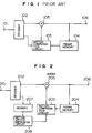
- a conventional digital video signal decoding apparatus is composed of an input terminal 101, a decoder 102, a motion compensation circuit 103, a frame memory 104, an adder 105, and an output terminal 106.
- the decoder 102 decodes a difference value of each pixel block between the previous frame and the current frame and a motion vector which was used for motion compensation of the pixel block in the previous frame. Then, the motion compensation circuit 103 uses the motion vectors inputted from the decoder 102 to motion-compensate the respective pixel blocks in the previous frame read out from the frame memory 104.
- the adder 105 adds the difference values of the respective pixel blocks between the previous frame and the current frame outputted from the decoder 102 to the values of the pixel blocks in the motion-compensated previous frame outputted from the motion compensation circuit 103 to reproduce the current frame.
- the reproduced current frame is delivered from the output terminal 106 and stored in the frame memory 104 for use in the decoding of a next frame.
- the conventional decoding apparatus described above can decode a video signal from a small amount of information including the difference values of the respective pixel blocks between the previous frame and the current frame and the motion vectors, and hence efficient video signal transmission can be accomplished.
- the present invention has been made to solve the above problem inherent to the prior art, and the object of the present invention is to provide a digital video signal decoding apparatus and a presumed motion vector calculating method which are effective for the case where a part a bit stream is lost and a corresponding pixel block cannot be decoded, and which are capable of preventing degradation of the picture quality at that pixel block portion.
- the digital video signal decoding apparatus of the present invention is provided with a memory for storing the values of motion vectors after they have been decoded so that, even if a part of a bit stream is lost and accordingly a corresponding pixel block cannot be decoded, this pixel block is replaced by a corresponding pixel block in the previous frame which has been motion-compensated by using a presumed motion vector calculated from the motion vectors stored in the memory, thereby making it possible to prevent degradation of the picture quality at that pixel block portion.
- the presumed motion vector calculating method counts the occurrence frequency of the values of N motion vectors stored in the memory in the x- and y-directions independently, and designates the motion vector of the largest frequency as a presumed motion vector.
- Another presumed motion vector calculating method adaptively changes the value of N when counting the occurrence frequency of the values of N motion vectors in the x- and y-directions independently in the above stated presumed motion vector calculating method.
- the present invention replaces a pixel block, which cannot be decoded, by a corresponding pixel block in the previous frame which has been motion-compensated by using a presumed motion vector, thereby preventing degradation of the picture quality.
- the presumed motion vector calculating method of the present invention employs the principle of making a decision by majority in selecting a presumed motion vector from N motion vector values, so that a most reliable presumed motion vector can be selected from the N motion vectors.
- a reliable motion vector can always be selected by adaptively changing the value of N so as to improve the picture quality.
- this motion vector calculating method can be used in a presumed motion vector calculating method applicable to the digital video signal decoding apparatus.
- a digital video signal decoding apparatus of the present embodiment is composed of an input terminal 201, a decoder 202, a memory 207, a motion vector presuming circuit 208, a motion compensation circuit 203, a frame memory 204, an adder 205, and an output terminal 206.
- the decoder 202 decodes a difference value of each pixel block between the previous frame and the current frame and a motion vector used for motion compensation of the pixel block of the previous frame, and stores the decoded motion vector in the memory 207. It should be noted, however, that, if the difference value and the motion vector cannot be decoded for some reason such as occurrence of a lost part of the bit stream, the decoder 202 does not output anything, so that no value is stored in the memory 207. It is assumed here that the memory 207 has a capacity of storing, for example, motion vectors per one-frame.
- the motion vector presuming circuit 208 reads a motion vector for each pixel block stored in the memory 207, and outputs a motion vector, if one for the corresponding pixel block exists, otherwise outputs a presumed motion vector.
- the motion compensation circuit 203 utilizes a motion vector inputted thereto from the motion vector presuming circuit 208 to motion-compensate each of the pixel blocks which constitute the previous frame read out from the frame memory 204.
- the adder 205 adds difference values of the respective pixel blocks between the previous frame and the current frame outputted from the decoder 202 to the corresponding pixel blocks in the motion-compensated previous frame outputted from the motion compensation circuit 203 to reproduce the current frame.
- the reproduced current frame is delivered from the output terminal 206 and simultaneously stored in the frame memory 204 for use in decoding a next frame.
- the digital video signal decoding apparatus of the present invention replaces a pixel block, which cannot be decoded, by a corresponding pixel block in the previous frame, which has been motion-compensated by using a presumed motion vector, to thereby prevent degradation of the picture quality.
- a presumed motion vector calculating method implemented in the motion vector presuming circuit 208 will be explained with reference to Figs. 3 and 4.
- a pixel block which cannot be decoded hereinafter referred to as "lost pixel block”
- loss pixel block a pixel block which cannot be decoded
- the motion vector presuming circuit 208 calculates a presumed motion vector, for example, through the following procedure:
- the occurrence frequencies may be weighted, as shown in Fig. 4, for example, when the presumed motion vector is calculated.
- the motion vector presuming circuit 208 employs a modified process (2) in the presumed motion vector calculating processes (1), (2) and (3) as described below.
- weighted occurrence frequencies are calculated for Vx(n) and Vy(n).
- the weighting coefficient is designated as w(n) which has a larger value at a position located closer to the lost pixel block, as shown in Fig. 4.
- This presumed motion vector calculating method employs a modified process (3) in the above described processes (1), (2) and (3) for calculating a presumed motion vector, as described below for example.
- a predetermined threshold value for example, two
- the vector values Vx(n) and Vy(n) which maximize the occurrence frequencies ax(Vx(n)) and ay(Vy(n)), respectively, are adopted as the presumed motion vector values.
- the presumed motion vector calculating processes (1), (2) and (3) are repeated for motion vector values of 14 decodable pixel blocks located around the lost pixel block, as shown in Fig. 5, for example.
- weighted occurrence frequencies may be calculated by using weighting coefficients shown in Fig. 6, as an example.
- the presumed motion vector calculating method of the present invention employs the principle of making a decision by majority for motion vector values of, for example, eight decodable pixel blocks around a lost pixel block to calculate a presumed motion vector for the lost pixel block, a most reliable one can be selected from the eight motion vectors, for example.
- 14 motion vectors may be used in place thereof for making the decision by majority, thereby making it possible to always select a reliable motion vector.
- degradation of the picture quality can be prevented by replacing a pixel block, which cannot be decoded, by a corresponding pixel block in the previous frame which has been motion-compensated by using a presumed motion vector.
- the presumed motion vector calculating method of the present invention since the principle of making a decision by majority is employed in selecting a presumed motion vector from N motion vector values, a most reliable one can be determined from the N motion vectors. Further, when the decision by majority is made for the N motion vectors, the value of N may be adaptively changed, thereby making it possible to always select a reliable motion vector.
Abstract
Description
- The present invention relates to a decoding apparatus and a presumed motion vector calculating method for digital video signals which are utilized in television telephones, tele-conferences and so on.
- In recent years, with the rapid development of television telephones and tele-conference apparatuses, a demand has arisen for a method of preventing degradation of the picture quality caused by a transmission error, particularly in a digital video signal decoding apparatus.
- Generally, a digital video signal coding apparatus first performs motion compensation for each of pixel blocks (for example, 16x16 pixels) which constitute the previous frame in order to remove correlation in time, and calculates a difference value of each pixel block between the previous frame and the current frame. In this case, an amount of information relating to the difference value is extremely smaller than an amount of information relating to the current frame. Then, the difference values and motion vectors used for the motion compensation are coded, and binary codes are outputted.
- On the other hand, a digital video signal decoding apparatus decodes the binary codes outputted from the coding apparatus to obtain a difference value of each pixel block between the motion-compensated previous frame and the current frame and a motion vector used for the motion compensation for that pixel block. The decoding apparatus is provided with a frame memory for storing the previous frame, and pixel blocks, which constitute the previous frame stored in the frame memory, are motion-compensated by using corresponding motion vectors, and the difference values are added to the motion compensated pixel blocks in the previous frame to thereby reproduce the current frame. The reproduced current frame is stored in the frame memory. In this manner, the decoding apparatus allows the current frame to be reproduced only by the use of the difference values of the respective pixel blocks between the previous frame and the current frame and the motion vectors.
- A conventional digital video signal decoding apparatus will be explained below with reference to Fig. 1.
- As shown in Fig. 1, a conventional digital video signal decoding apparatus is composed of an
input terminal 101, adecoder 102, amotion compensation circuit 103, aframe memory 104, anadder 105, and anoutput terminal 106. - Next, the relation between the respective constituent elements and the operation of the apparatus shown in Fig. 1 will be explained.
- When a binary code is first supplied from a coding apparatus to the
input terminal 101, thedecoder 102 decodes a difference value of each pixel block between the previous frame and the current frame and a motion vector which was used for motion compensation of the pixel block in the previous frame. Then, themotion compensation circuit 103 uses the motion vectors inputted from thedecoder 102 to motion-compensate the respective pixel blocks in the previous frame read out from theframe memory 104. Theadder 105 adds the difference values of the respective pixel blocks between the previous frame and the current frame outputted from thedecoder 102 to the values of the pixel blocks in the motion-compensated previous frame outputted from themotion compensation circuit 103 to reproduce the current frame. The reproduced current frame is delivered from theoutput terminal 106 and stored in theframe memory 104 for use in the decoding of a next frame. - Thus, the conventional decoding apparatus described above, as an example, can decode a video signal from a small amount of information including the difference values of the respective pixel blocks between the previous frame and the current frame and the motion vectors, and hence efficient video signal transmission can be accomplished.
- However, in the above-described conventional structure, if a part of a bit stream is lost on a transmission path for some reason, there may occur a pixel block in which the difference value between the previous frame and the current frame and the motion vector cannot be decoded, whereby pixels in such a pixel block in the previous frame which have not been subjected to motion compensation are displayed in a portion of the frame, causing a problem that the picture quality is greatly degraded, particularly in a moving portion.
- The present invention has been made to solve the above problem inherent to the prior art, and the object of the present invention is to provide a digital video signal decoding apparatus and a presumed motion vector calculating method which are effective for the case where a part a bit stream is lost and a corresponding pixel block cannot be decoded, and which are capable of preventing degradation of the picture quality at that pixel block portion.
- To achieve the above object, the digital video signal decoding apparatus of the present invention is provided with a memory for storing the values of motion vectors after they have been decoded so that, even if a part of a bit stream is lost and accordingly a corresponding pixel block cannot be decoded, this pixel block is replaced by a corresponding pixel block in the previous frame which has been motion-compensated by using a presumed motion vector calculated from the motion vectors stored in the memory, thereby making it possible to prevent degradation of the picture quality at that pixel block portion.
- Further, the presumed motion vector calculating method counts the occurrence frequency of the values of N motion vectors stored in the memory in the x- and y-directions independently, and designates the motion vector of the largest frequency as a presumed motion vector.
- Another presumed motion vector calculating method according to the present invention adaptively changes the value of N when counting the occurrence frequency of the values of N motion vectors in the x- and y-directions independently in the above stated presumed motion vector calculating method.
- With the configuration described above, the present invention replaces a pixel block, which cannot be decoded, by a corresponding pixel block in the previous frame which has been motion-compensated by using a presumed motion vector, thereby preventing degradation of the picture quality.
- The presumed motion vector calculating method of the present invention, on the other hand, employs the principle of making a decision by majority in selecting a presumed motion vector from N motion vector values, so that a most reliable presumed motion vector can be selected from the N motion vectors.
- Further, a reliable motion vector can always be selected by adaptively changing the value of N so as to improve the picture quality.
- In addition, this motion vector calculating method can be used in a presumed motion vector calculating method applicable to the digital video signal decoding apparatus.
-
- Fig. 1 is a block diagram showing a conventional digital video signal decoding apparatus;
- Fig. 2 is a block diagram showing a digital video signal decoding apparatus according to one embodiment of the present invention;
- Fig. 3 is a diagram showing an arrangement of pixel blocks used for explaining a presumed motion vector calculating method according to the present invention;
- Fig. 4 is a diagram showing pixel blocks used for explaining a different presumed motion vector calculating method according to the present invention;
- Fig. 5 is a diagram showing pixel blocks used for explaining another presumed motion vector calculating method according to the present invention; and
- Fig. 6 is a diagram showing pixel blocks used for explaining a further presumed motion vector calculating method according to the present invention.
- One embodiment of the present invention will hereinafter be described with reference to the accompanying drawings.
- As shown in Fig. 2, a digital video signal decoding apparatus of the present embodiment is composed of an
input terminal 201, adecoder 202, amemory 207, a motionvector presuming circuit 208, amotion compensation circuit 203, aframe memory 204, anadder 205, and anoutput terminal 206. - The operation of the decoding apparatus will next be explained.
- First, when a binary code sequence (hereinafter abbreviated as "bit stream") outputted from a coding apparatus is supplied from the
input terminal 201, thedecoder 202 decodes a difference value of each pixel block between the previous frame and the current frame and a motion vector used for motion compensation of the pixel block of the previous frame, and stores the decoded motion vector in thememory 207. It should be noted, however, that, if the difference value and the motion vector cannot be decoded for some reason such as occurrence of a lost part of the bit stream, thedecoder 202 does not output anything, so that no value is stored in thememory 207. It is assumed here that thememory 207 has a capacity of storing, for example, motion vectors per one-frame. - Next, the motion
vector presuming circuit 208 reads a motion vector for each pixel block stored in thememory 207, and outputs a motion vector, if one for the corresponding pixel block exists, otherwise outputs a presumed motion vector. - The
motion compensation circuit 203 utilizes a motion vector inputted thereto from the motionvector presuming circuit 208 to motion-compensate each of the pixel blocks which constitute the previous frame read out from theframe memory 204. Theadder 205 adds difference values of the respective pixel blocks between the previous frame and the current frame outputted from thedecoder 202 to the corresponding pixel blocks in the motion-compensated previous frame outputted from themotion compensation circuit 203 to reproduce the current frame. The reproduced current frame is delivered from theoutput terminal 206 and simultaneously stored in theframe memory 204 for use in decoding a next frame. - As described above, the digital video signal decoding apparatus of the present invention replaces a pixel block, which cannot be decoded, by a corresponding pixel block in the previous frame, which has been motion-compensated by using a presumed motion vector, to thereby prevent degradation of the picture quality.
- Next, a presumed motion vector calculating method implemented in the motion
vector presuming circuit 208 will be explained with reference to Figs. 3 and 4. In the digital video signal decoding apparatus of the present embodiment, a pixel block which cannot be decoded (hereinafter referred to as "lost pixel block") is replaced by a corresponding pixel block in the previous frame which has been motion-compensated by using a presumed motion vector. Therefore, as the presumed motion vector value is closer to an original motion vector value of the lost pixel block, degradation of the picture quality of the lost pixel block portion becomes less conspicuous. - The motion
vector presuming circuit 208 calculates a presumed motion vector, for example, through the following procedure: - (1) Motion vector values of eight decodable pixel blocks around a lost pixel block, as shown in Fig. 3, for example, are examined in the x- and y-directions independently, and these motion vector values are designated Vx(n) and Vy(n), respectively, where n designates an index corresponding to the position of each decodable pixel block shown in Fig. 3 and may take a value in a range expressed by 1 ≦ n ≦ 8 in this example.
- (2) For the range 1 ≦ n ≦ 8, the occurrence times are counted for Vx(n) and Vy(n). More specifically, the occurrence frequency ax(Vx(n)) of Vx(n) is calculated for all of n values as:


- (3) Each of the motion vector values Vx(n) and Vy(n), which has the largest occurrence frequency ax(Vx(n)) and ay(Vy(n)) is adopted as a presumed motion vector value.
- Also, from the fact that a motion vector of a pixel block located closer to a lost pixel block has a higher probability of presenting a value identical or close to the original motion vector value of the lost pixel block, the occurrence frequencies may be weighted, as shown in Fig. 4, for example, when the presumed motion vector is calculated. When this weighting is performed, the motion
vector presuming circuit 208 employs a modified process (2) in the presumed motion vector calculating processes (1), (2) and (3) as described below.
(2) For the range 1 ≦ n ≦ 8, weighted occurrence frequencies are calculated for Vx(n) and Vy(n). The weighting coefficient is designated as w(n) which has a larger value at a position located closer to the lost pixel block, as shown in Fig. 4. The weighted occurrence frequency ax(Vx(n)) for Vx(n) is calculated for all of the values of n, as indicated by
Likewise, the weighted occurrence frequency ay(Vy(n)) for Vy(n) is calculated as indicated by
- While only one example of the embodiment of the presumed motion vector calculating method has been explained, it is to be understood that this is a mere example, and other motion vectors of pixel blocks shown in Fig. 3 may be used for calculating the presumed motion vector. Also, the values other than those shown in Fig. 4 may be used for the weighting coefficients for the pixel blocks.
- Another presumed motion vector calculating method will be next explained with reference to Figs. 5 and 6. This presumed motion vector calculating method employs a modified process (3) in the above described processes (1), (2) and (3) for calculating a presumed motion vector, as described below for example.
(3) When both of the largest values of the occurrence frequencies ax(Vx(n)) and ay(Vy(n)) exceed a predetermined threshold value (for example, two), the vector values Vx(n) and Vy(n), which maximize the occurrence frequencies ax(Vx(n)) and ay(Vy(n)), respectively, are adopted as the presumed motion vector values. Conversely, if any one or both of the maximum values of the occurrence frequencies ax(Vx(n)) and ay(Vy(n)) has a value of two or less, the presumed motion vector calculating processes (1), (2) and (3) are repeated for motion vector values of 14 decodable pixel blocks located around the lost pixel block, as shown in Fig. 5, for example. - Further, in the process (2), weighted occurrence frequencies may be calculated by using weighting coefficients shown in Fig. 6, as an example.
- While the different embodiment of the presumed motion vector calculating method has been explained above, it is to be understood that this is a mere example, and any motion vectors of pixel blocks other than those shown in Fig. 5 may be used for calculating the presumed motion vectors. Also, the values other than those shown in Fig. 6 may be used for the weighting coefficients for the pixel blocks.
- As described above, since the presumed motion vector calculating method of the present invention employs the principle of making a decision by majority for motion vector values of, for example, eight decodable pixel blocks around a lost pixel block to calculate a presumed motion vector for the lost pixel block, a most reliable one can be selected from the eight motion vectors, for example.
- Further, assuming, for example, that eight motion vector values vary so greatly that the decision by majority for the eight motion vector values cannot be made, 14 motion vectors, for example, may be used in place thereof for making the decision by majority, thereby making it possible to always select a reliable motion vector.
- As is apparent from the foregoing embodiments, according to the digital video signal decoding apparatus of the present invention, degradation of the picture quality can be prevented by replacing a pixel block, which cannot be decoded, by a corresponding pixel block in the previous frame which has been motion-compensated by using a presumed motion vector.
- Also, in accordance with the presumed motion vector calculating method of the present invention, since the principle of making a decision by majority is employed in selecting a presumed motion vector from N motion vector values, a most reliable one can be determined from the N motion vectors. Further, when the decision by majority is made for the N motion vectors, the value of N may be adaptively changed, thereby making it possible to always select a reliable motion vector.
- According to the present invention, therefore, it is possible to realize excellent digital video signal decoding apparatus and presumed motion vector calculating method which cannot be achieved by the prior art.
Claims (3)
- A digital video signal decoding apparatus comprising:
a decoder (202) for decoding, from a binary code sequence of digital video signals inputted in the form of a bit stream, motion vectors [Vx(n), Vy(n)] for each of frame pixel blocks;
a memory (207) for storing values of the motion vectors [Vx(n), Vy(n)];
a motion vector presuming circuit (208) for calculating a presumed motion vector from the motion vectors [Vx(n), Vy(n)] stored in said memory (207); and
a motion compensation circuit (203) for motion-compensating each of the frame pixel blocks using the presumed motion vector or the motion vector [Vx(n), Vy(n)] read out directly from said memory (207). - A presumed motion vector calculating method comprising the steps of:
storing values of motion vectors [Vx(n), Vy(n)] in a memory (207);
counting occurrence frequency [ax(Vx(n)), ay(Vy(n))] of the values of N motion vectors stored in said memory (207) in the x- and y-directions independently of each other; and
adopting one of the motion vectors [Vx(n), Vy(n))] having the largest occurrence frequency [ax(Vx(n)), ay(Vy(n))] as a presumed motion vector. - A presumed motion vector calculating method according to claim 2, wherein the step of counting occurrence frequency [ax(Vx(n)), ay(Vy(n))] of the values of N motion vectors stored in said memory (207) in the x- and y-directions independently of each other includes adaptively changing the value of N.
Applications Claiming Priority (2)
| Application Number | Priority Date | Filing Date | Title |
|---|---|---|---|
| JP4176609A JPH0620050A (en) | 1992-07-03 | 1992-07-03 | Dynamic image signal decoding device and estimated motion vector calculation method |
| JP176609/92 | 1992-07-03 |
Publications (3)
| Publication Number | Publication Date |
|---|---|
| EP0577417A2 true EP0577417A2 (en) | 1994-01-05 |
| EP0577417A3 EP0577417A3 (en) | 1994-08-17 |
| EP0577417B1 EP0577417B1 (en) | 1998-08-19 |
Family
ID=16016564
Family Applications (1)
| Application Number | Title | Priority Date | Filing Date |
|---|---|---|---|
| EP93305145A Expired - Lifetime EP0577417B1 (en) | 1992-07-03 | 1993-06-30 | Digital video signal decoding apparatus and presumed motion vector calculating method |
Country Status (6)
| Country | Link |
|---|---|
| US (1) | US5552831A (en) |
| EP (1) | EP0577417B1 (en) |
| JP (1) | JPH0620050A (en) |
| AU (1) | AU650391B2 (en) |
| CA (1) | CA2099407C (en) |
| DE (1) | DE69320430T2 (en) |
Cited By (4)
| Publication number | Priority date | Publication date | Assignee | Title |
|---|---|---|---|---|
| EP0645933A2 (en) * | 1993-09-28 | 1995-03-29 | Canon Kabushiki Kaisha | Image reproducing apparatus |
| FR2725577A1 (en) * | 1994-10-10 | 1996-04-12 | Thomson Consumer Electronics | METHOD FOR ENCODING OR DECODING MOTION VECTORS AND DEVICE FOR ENCODING OR DECODING USING SAID METHOD |
| GB2277655B (en) * | 1993-04-30 | 1998-02-25 | Samsung Electronics Co Ltd | Digital signal processing system |
| GB2316570A (en) * | 1993-04-30 | 1998-02-25 | Samsung Electronics Co Ltd | Video signal error-correction-decoding using motion vector data |
Families Citing this family (22)
| Publication number | Priority date | Publication date | Assignee | Title |
|---|---|---|---|---|
| US5809173A (en) * | 1995-04-18 | 1998-09-15 | Advanced Micro Devices, Inc. | Method and apparatus for improved video decompression using previous frame DCT coefficients |
| US5724446A (en) * | 1995-04-18 | 1998-03-03 | Advanced Micro Devices, Inc. | Video decoder apparatus using non-reference frame as an additional prediction source and method therefor |
| US5774600A (en) * | 1995-04-18 | 1998-06-30 | Advanced Micro Devices, Inc. | Method of pixel averaging in a video processing apparatus |
| US5724369A (en) * | 1995-10-26 | 1998-03-03 | Motorola Inc. | Method and device for concealment and containment of errors in a macroblock-based video codec |
| JPH09128529A (en) * | 1995-10-30 | 1997-05-16 | Sony Corp | Removing method for noise in digital image based on projection |
| JP3994445B2 (en) * | 1995-12-05 | 2007-10-17 | ソニー株式会社 | Motion vector detection apparatus and motion vector detection method |
| TW357327B (en) * | 1996-08-02 | 1999-05-01 | Sony Corp | Methods, apparatus and program storage device for removing scratch or wire noise, and recording media therefor |
| US6005624A (en) * | 1996-12-20 | 1999-12-21 | Lsi Logic Corporation | System and method for performing motion compensation using a skewed tile storage format for improved efficiency |
| US6078616A (en) * | 1997-03-13 | 2000-06-20 | Sony Corporation | Methods and apparatus for error concealment utilizing temporal domain motion vector estimation |
| US6519287B1 (en) * | 1998-07-13 | 2003-02-11 | Motorola, Inc. | Method and apparatus for encoding and decoding video signals by using storage and retrieval of motion vectors |
| KR20010058887A (en) * | 1999-12-30 | 2001-07-06 | 구자홍 | Apparatus for 3-d recursive motion vector estimation using the gradient of video signal |
| US7221761B1 (en) | 2000-09-18 | 2007-05-22 | Sharp Laboratories Of America, Inc. | Error resilient digital video scrambling |
| US7403563B2 (en) * | 2002-06-07 | 2008-07-22 | Sanyo Electric Co., Ltd. | Image decoding method and apparatus, and television receiver utilizing the same |
| US7817717B2 (en) * | 2002-06-18 | 2010-10-19 | Qualcomm Incorporated | Motion estimation techniques for video encoding |
| US7020207B1 (en) | 2002-12-02 | 2006-03-28 | Hitachi, Ltd. | Video error concealment mechanism for block based video decompression |
| US7705884B2 (en) * | 2004-07-21 | 2010-04-27 | Zoran Corporation | Processing of video data to compensate for unintended camera motion between acquired image frames |
| US8139647B2 (en) | 2004-10-29 | 2012-03-20 | Sharp Kabushiki Kaisha | Moving image decoding apparatus and moving image decoding method |
| JP4509809B2 (en) * | 2005-01-21 | 2010-07-21 | パイオニア株式会社 | Digital image decoding apparatus and method |
| KR100705929B1 (en) * | 2005-09-28 | 2007-04-12 | 엘지전자 주식회사 | Compensation Apparatus for motion in the mobile terminal |
| KR20120068743A (en) | 2010-12-17 | 2012-06-27 | 한국전자통신연구원 | Method for inter prediction and apparatus thereof |
| GB2487200A (en) | 2011-01-12 | 2012-07-18 | Canon Kk | Video encoding and decoding with improved error resilience |
| GB2491589B (en) | 2011-06-06 | 2015-12-16 | Canon Kk | Method and device for encoding a sequence of images and method and device for decoding a sequence of image |
Citations (1)
| Publication number | Priority date | Publication date | Assignee | Title |
|---|---|---|---|---|
| EP0521529A2 (en) * | 1991-07-04 | 1993-01-07 | Fujitsu Limited | An image encoding and transmitting system |
Family Cites Families (10)
| Publication number | Priority date | Publication date | Assignee | Title |
|---|---|---|---|---|
| US4727422A (en) * | 1985-06-03 | 1988-02-23 | Picturetel Corporation | Method and apparatus for efficiently communicating image sequence having improved motion compensation |
| JPS63502074A (en) * | 1985-12-24 | 1988-08-11 | ブリティッシュ・ブロ−ドキャスティング・コ−ポレ−ション | Video signal decoding method and device |
| EP0294955B1 (en) * | 1987-06-09 | 1995-04-12 | Sony Corporation | Motion vector estimation in television images |
| EP0294956B1 (en) * | 1987-06-09 | 1994-07-20 | Sony Corporation | Motion vector reduction in television images |
| GB2231751B (en) * | 1989-04-27 | 1993-09-22 | Sony Corp | Motion dependent video signal processing |
| GB2231227B (en) * | 1989-04-27 | 1993-09-29 | Sony Corp | Motion dependent video signal processing |
| AU612543B2 (en) * | 1989-05-11 | 1991-07-11 | Panasonic Corporation | Moving image signal encoding apparatus and decoding apparatus |
| GB8914843D0 (en) * | 1989-06-28 | 1989-08-16 | British Aerospace | A method of processing video image data for use in the storage or transmission of moving digital images |
| JP3159309B2 (en) * | 1989-09-27 | 2001-04-23 | ソニー株式会社 | Video signal encoding method and video signal encoding device |
| US5198901A (en) * | 1991-09-23 | 1993-03-30 | Matsushita Electric Corporation Of America | Derivation and use of motion vectors in a differential pulse code modulation system |
-
1992
- 1992-07-03 JP JP4176609A patent/JPH0620050A/en active Pending
-
1993
- 1993-06-30 DE DE69320430T patent/DE69320430T2/en not_active Expired - Fee Related
- 1993-06-30 CA CA002099407A patent/CA2099407C/en not_active Expired - Fee Related
- 1993-06-30 EP EP93305145A patent/EP0577417B1/en not_active Expired - Lifetime
- 1993-07-02 AU AU41716/93A patent/AU650391B2/en not_active Ceased
-
1995
- 1995-06-06 US US08/467,719 patent/US5552831A/en not_active Expired - Lifetime
Patent Citations (1)
| Publication number | Priority date | Publication date | Assignee | Title |
|---|---|---|---|---|
| EP0521529A2 (en) * | 1991-07-04 | 1993-01-07 | Fujitsu Limited | An image encoding and transmitting system |
Non-Patent Citations (3)
| Title |
|---|
| ICASSP '88, INT. CONF. ON ACOUSTICS, SPEECH, AND SIGNAL PROCESSING, vol.II, 11 April 1988, IEEE, NEW YORK, US; pages 1312 - 1315 G.AARTSEN ET AL. 'Error resilience of a video codec for low bitrates' * |
| ICASSP '92, INT. CONF. ON ACOUSTICS, SPEECH AND SIGNAL PROCESSING, vol.3, 23 March 1992, IEEE, NEW YORK, US; pages III.545 - III.548 P.HASKELL ET AL. 'Resynchronization of motion compensated video affected by ATM cell loss' * |
| IEEE JOURNAL ON SELECTED AREAS IN COMMUNICATION, vol.7, no.5, June 1989, NEW YORK US pages 807 - 814 M.WADA 'Selective recovery of video packet loss using error concealment' * |
Cited By (10)
| Publication number | Priority date | Publication date | Assignee | Title |
|---|---|---|---|---|
| GB2277655B (en) * | 1993-04-30 | 1998-02-25 | Samsung Electronics Co Ltd | Digital signal processing system |
| GB2316570A (en) * | 1993-04-30 | 1998-02-25 | Samsung Electronics Co Ltd | Video signal error-correction-decoding using motion vector data |
| GB2316570B (en) * | 1993-04-30 | 1998-04-08 | Samsung Electronics Co Ltd | Digital signal processing system |
| EP0645933A2 (en) * | 1993-09-28 | 1995-03-29 | Canon Kabushiki Kaisha | Image reproducing apparatus |
| EP0645933A3 (en) * | 1993-09-28 | 1996-01-17 | Canon Kk | Image reproducing apparatus. |
| US6327391B1 (en) | 1993-09-28 | 2001-12-04 | Canon Kabushiki Kaisha | Protecting image quality from occurrence of uncorrectable errors |
| FR2725577A1 (en) * | 1994-10-10 | 1996-04-12 | Thomson Consumer Electronics | METHOD FOR ENCODING OR DECODING MOTION VECTORS AND DEVICE FOR ENCODING OR DECODING USING SAID METHOD |
| EP0707428A1 (en) * | 1994-10-10 | 1996-04-17 | Wang, Pierre | Motion vector differential coding method with median prediction |
| US5905535A (en) * | 1994-10-10 | 1999-05-18 | Thomson Multimedia S.A. | Differential coding of motion vectors using the median of candidate vectors |
| CN1112046C (en) * | 1994-10-10 | 2003-06-18 | 汤姆森多媒体公司 | Coding or the method for decoding motion vectors and the coding or the decoding device of its enforcement |
Also Published As
| Publication number | Publication date |
|---|---|
| DE69320430D1 (en) | 1998-09-24 |
| EP0577417A3 (en) | 1994-08-17 |
| CA2099407A1 (en) | 1994-01-04 |
| AU650391B2 (en) | 1994-06-16 |
| CA2099407C (en) | 1999-02-23 |
| US5552831A (en) | 1996-09-03 |
| JPH0620050A (en) | 1994-01-28 |
| AU4171693A (en) | 1994-01-06 |
| EP0577417B1 (en) | 1998-08-19 |
| DE69320430T2 (en) | 1999-02-18 |
Similar Documents
| Publication | Publication Date | Title |
|---|---|---|
| US5552831A (en) | Digital video signal decoding apparatus and presumed motion vector calculating method | |
| KR100317412B1 (en) | Video Signal Compressor Using Noise Reduction | |
| EP0484140B1 (en) | Compression method of interlace moving image signals | |
| US5351083A (en) | Picture encoding and/or decoding system | |
| EP0615384B1 (en) | Adaptive compression of digital video data | |
| US6285710B1 (en) | Noise estimation and reduction apparatus for video signal processing | |
| KR100261072B1 (en) | Digital signal processing system | |
| EP1044566B1 (en) | Improved video coding and decoding using adaptive coding of block parameters for coded/uncoded blocks | |
| US5438374A (en) | System and method for filtering video signals | |
| KR0125581B1 (en) | Error correction system of digital video signal | |
| US5781561A (en) | Encoding apparatus for hierarchically encoding image signal and decoding apparatus for decoding the image signal hierarchically encoded by the encoding apparatus | |
| US6025888A (en) | Method and apparatus for improved error recovery in video transmission over wireless channels | |
| US4571618A (en) | TV Signal median prediction coding system | |
| US6415055B1 (en) | Moving image encoding method and apparatus, and moving image decoding method and apparatus | |
| US5991445A (en) | Image processing apparatus | |
| US7302003B2 (en) | Method and device for image interpolation with motion compensation | |
| US5555029A (en) | Method and apparatus for post-processing decoded image data | |
| US5818535A (en) | Method and apparatus for adaptive hybrid motion video compression and decompression | |
| US6697425B1 (en) | Dynamic image encoding apparatus and method for encoding a dynamic image | |
| US6339615B1 (en) | Picture encoding device, picture encoding method, picture decoding device, picture decoding method, and recording medium | |
| US20020141649A1 (en) | Coding method, coding apparatus, decoding method and decoding apparatus using subsampling | |
| JPH04275790A (en) | Image processor | |
| US5841375A (en) | Information signal encoding apparatus, encoding method thereof, information signal decoding method, and information signal medium thereof | |
| US5574568A (en) | Video recording and reproducing apparatus | |
| RU2154917C2 (en) | Improved final processing method and device for image signal decoding system |
Legal Events
| Date | Code | Title | Description |
|---|---|---|---|
| PUAI | Public reference made under article 153(3) epc to a published international application that has entered the european phase |
Free format text: ORIGINAL CODE: 0009012 |
|
| AK | Designated contracting states |
Kind code of ref document: A2 Designated state(s): BE DE FR GB NL |
|
| 17P | Request for examination filed |
Effective date: 19940211 |
|
| PUAL | Search report despatched |
Free format text: ORIGINAL CODE: 0009013 |
|
| AK | Designated contracting states |
Kind code of ref document: A3 Designated state(s): BE DE FR GB NL |
|
| 17Q | First examination report despatched |
Effective date: 19961002 |
|
| GRAG | Despatch of communication of intention to grant |
Free format text: ORIGINAL CODE: EPIDOS AGRA |
|
| GRAG | Despatch of communication of intention to grant |
Free format text: ORIGINAL CODE: EPIDOS AGRA |
|
| GRAH | Despatch of communication of intention to grant a patent |
Free format text: ORIGINAL CODE: EPIDOS IGRA |
|
| GRAH | Despatch of communication of intention to grant a patent |
Free format text: ORIGINAL CODE: EPIDOS IGRA |
|
| GRAA | (expected) grant |
Free format text: ORIGINAL CODE: 0009210 |
|
| AK | Designated contracting states |
Kind code of ref document: B1 Designated state(s): BE DE FR GB NL |
|
| REF | Corresponds to: |
Ref document number: 69320430 Country of ref document: DE Date of ref document: 19980924 |
|
| ET | Fr: translation filed | ||
| PLBE | No opposition filed within time limit |
Free format text: ORIGINAL CODE: 0009261 |
|
| STAA | Information on the status of an ep patent application or granted ep patent |
Free format text: STATUS: NO OPPOSITION FILED WITHIN TIME LIMIT |
|
| 26N | No opposition filed | ||
| REG | Reference to a national code |
Ref country code: GB Ref legal event code: IF02 |
|
| PGFP | Annual fee paid to national office [announced via postgrant information from national office to epo] |
Ref country code: NL Payment date: 20070617 Year of fee payment: 15 |
|
| PGFP | Annual fee paid to national office [announced via postgrant information from national office to epo] |
Ref country code: DE Payment date: 20070628 Year of fee payment: 15 |
|
| PGFP | Annual fee paid to national office [announced via postgrant information from national office to epo] |
Ref country code: GB Payment date: 20070627 Year of fee payment: 15 |
|
| PGFP | Annual fee paid to national office [announced via postgrant information from national office to epo] |
Ref country code: BE Payment date: 20070817 Year of fee payment: 15 |
|
| PGFP | Annual fee paid to national office [announced via postgrant information from national office to epo] |
Ref country code: FR Payment date: 20070608 Year of fee payment: 15 |
|
| BERE | Be: lapsed |
Owner name: *MATSUSHITA ELECTRIC INDUSTRIAL CO. LTD Effective date: 20080630 |
|
| GBPC | Gb: european patent ceased through non-payment of renewal fee |
Effective date: 20080630 |
|
| NLV4 | Nl: lapsed or anulled due to non-payment of the annual fee |
Effective date: 20090101 |
|
| PG25 | Lapsed in a contracting state [announced via postgrant information from national office to epo] |
Ref country code: BE Free format text: LAPSE BECAUSE OF NON-PAYMENT OF DUE FEES Effective date: 20080630 |
|
| REG | Reference to a national code |
Ref country code: FR Ref legal event code: ST Effective date: 20090228 |
|
| PG25 | Lapsed in a contracting state [announced via postgrant information from national office to epo] |
Ref country code: DE Free format text: LAPSE BECAUSE OF NON-PAYMENT OF DUE FEES Effective date: 20090101 |
|
| PG25 | Lapsed in a contracting state [announced via postgrant information from national office to epo] |
Ref country code: NL Free format text: LAPSE BECAUSE OF NON-PAYMENT OF DUE FEES Effective date: 20090101 |
|
| PG25 | Lapsed in a contracting state [announced via postgrant information from national office to epo] |
Ref country code: GB Free format text: LAPSE BECAUSE OF NON-PAYMENT OF DUE FEES Effective date: 20080630 |
|
| PG25 | Lapsed in a contracting state [announced via postgrant information from national office to epo] |
Ref country code: FR Free format text: LAPSE BECAUSE OF NON-PAYMENT OF DUE FEES Effective date: 20080630 |