EP0579451A1 - Method of and apparatus for producing an animation having a series of road drawings to be watched from a driver's seat of a vehicle - Google Patents
Method of and apparatus for producing an animation having a series of road drawings to be watched from a driver's seat of a vehicle Download PDFInfo
- Publication number
- EP0579451A1 EP0579451A1 EP93305354A EP93305354A EP0579451A1 EP 0579451 A1 EP0579451 A1 EP 0579451A1 EP 93305354 A EP93305354 A EP 93305354A EP 93305354 A EP93305354 A EP 93305354A EP 0579451 A1 EP0579451 A1 EP 0579451A1
- Authority
- EP
- European Patent Office
- Prior art keywords
- road
- data
- animation
- vehicle
- travel route
- Prior art date
- Legal status (The legal status is an assumption and is not a legal conclusion. Google has not performed a legal analysis and makes no representation as to the accuracy of the status listed.)
- Granted
Links
Images


Classifications
-
- G—PHYSICS
- G01—MEASURING; TESTING
- G01C—MEASURING DISTANCES, LEVELS OR BEARINGS; SURVEYING; NAVIGATION; GYROSCOPIC INSTRUMENTS; PHOTOGRAMMETRY OR VIDEOGRAMMETRY
- G01C21/00—Navigation; Navigational instruments not provided for in groups G01C1/00 - G01C19/00
- G01C21/26—Navigation; Navigational instruments not provided for in groups G01C1/00 - G01C19/00 specially adapted for navigation in a road network
-
- G—PHYSICS
- G06—COMPUTING; CALCULATING OR COUNTING
- G06T—IMAGE DATA PROCESSING OR GENERATION, IN GENERAL
- G06T15/00—3D [Three Dimensional] image rendering
- G06T15/10—Geometric effects
-
- G—PHYSICS
- G08—SIGNALLING
- G08G—TRAFFIC CONTROL SYSTEMS
- G08G1/00—Traffic control systems for road vehicles
- G08G1/09—Arrangements for giving variable traffic instructions
- G08G1/0962—Arrangements for giving variable traffic instructions having an indicator mounted inside the vehicle, e.g. giving voice messages
- G08G1/0968—Systems involving transmission of navigation instructions to the vehicle
- G08G1/0969—Systems involving transmission of navigation instructions to the vehicle having a display in the form of a map
-
- G—PHYSICS
- G09—EDUCATION; CRYPTOGRAPHY; DISPLAY; ADVERTISING; SEALS
- G09B—EDUCATIONAL OR DEMONSTRATION APPLIANCES; APPLIANCES FOR TEACHING, OR COMMUNICATING WITH, THE BLIND, DEAF OR MUTE; MODELS; PLANETARIA; GLOBES; MAPS; DIAGRAMS
- G09B29/00—Maps; Plans; Charts; Diagrams, e.g. route diagram
- G09B29/10—Map spot or coordinate position indicators; Map reading aids
- G09B29/106—Map spot or coordinate position indicators; Map reading aids using electronic means
Definitions
- the present invention relates to a method of and an apparatus for producing an animation having a series of road drawings to be watched from a driver's seat.
- the road drawings are obtained on the basis of road map data through three-dimensional computer graphics.
- the present invention has been made to overcome the foregoing problems in the prior art, and a first object of the present invention is to provide a method of producing an animation having a series of road drawings showing roads which are in existence.
- the foregoing first object of the present invention can be achieved by providing a method of producing an animation having a series of road drawings to be watched from a driver's seat of a vehicle during a travel between two predetermined positions in a road map, the road drawings being formed on the basis of road data obtained through three-dimensional computer graphics, and the road data being indicative of roads shown in the animation, comprising the steps of: preparing travel route data providing means for providing travel route data indicative of a travel route between the predetermined positions, and road map data storing means for storing road map data including node data indicative of nodes formed by intersections, corners and ends of roads, link data indicative of links each connecting two of the nodes to define a road segment, and road width data indicative of the widths of the road segments, selecting from the road map data storing means the road map data covering the travel route based on the provided travel route data, and calculating the road data on the basis of the selected road map data to produce the animation in such a manner that the roads are three-dimensionally shown in the road drawings.
- the foregoing first object of the present invention can be achieved by providing a method of producing an animation having a series of road drawings to be watched from a driver's seat of a vehicle during a travel between two predetermined positions in a road map, the road drawings being formed on the basis of road data and background data obtained through three-dimensional computer graphics, and the road data and the background data being indicative of roads and backgrounds, respectively, shown in the animation, comprising the steps of: preparing travel route data providing means for providing travel route data indicative of a travel route between the predetermined positions, road map data storing means for storing road map data including node data indicative of nodes formed by intersections, corners and ends of roads, link data indicative of links each connecting two of the nodes to define a road segment and road width data indicative of the widths of the road segments, and random number generating means for generating random numbers, selecting from the road map data storing means the road map data covering the travel route based on the travel route data, calculating the road data on the basis of the selected road map data to produce the animation in such
- the foregoing second object of the present invention can be achieved by providing an apparatus for producing an animation having a series of road drawings to be watched from a driver's seat of a vehicle during a travel from the current position of the vehicle to a destination, the road drawings being formed on the basis of road data and background data obtained through three-dimensional computer graphics, and the road data and the background data being indicative of roads and backgrounds, respectively, shown in the animation, comprising: vehicle position detecting means for detecting the current position of the vehicle, optimum travel route data calculating means for calculating optimum travel route data indicative of an optimum travel route between the current position of the vehicle and the destination, road map data storing means for storing road map data to be referred to during the travel on the optimum travel route, road map data selecting means for selecting from the road map data storing means the road map data covering the optimum travel route, road data calculating means for calculating the road data on the basis of the selected road map data to produce the animation in such a manner that the roads are three-dimensionally shown in the road drawings, background data calculating
- the animation produced by the animation producing system has a series of road drawings to be watched from a driver's seat of a vehicle during a travel between two predetermined positions in a road map.
- the road drawings are formed on the basis of road data and background data obtained through three-dimensional computer graphics.
- the road data and the background data are indicative of roads and backgrounds, respectively, shown in the animation, and integrally forms road drawing data indicative of the road drawings.
- Fig. 1 is a block diagram showing the animation producing system which comprises a road map data base device 1, a navigation apparatus 2, a flexible disk 3, a calculator 4, road drawing forming equipment 5, a video tape recorder (hereinlater simply referred to as "VTR") 6, and an animation data base device 7.
- VTR video tape recorder
- the flexible disk 3 stores and provides travel route data indicative of a travel route between the aforementioned predetermined positions, i.e., to be traveled by the vehicle. Additionally, the travel route data includes travel speed data indicative of the travel speed of the vehicle in the animation. The advance speed of the animation is determined in such a manner as to be varied in response to the travel speed of the vehicle.
- the road map data base device 1 such as for example a CD-ROM (Compact Disc of Read Only Memory) stores road map data formed by the whole country map data base providing maps drawn to a scale of for example 1/2,500.
- the road map data are indicative of road maps formed by a plurality of nodes and a plurality of links.
- the road map data include node data indicative of nodes formed by intersections, corners and ends of roads, link data indicative of links each connecting two of the nodes to define a road segment and road width data indicative of the widths of the road segments.
- the positions of the nodes are represented by coordinates.
- Each of the links is to be represented as a vector defined by coordinates of two nodes connected by the link.
- the navigation apparatus 2 is adapted to generate leading indication data indicative of the travel route, the current position of the vehicle and the advance direction in which the vehicle is to advance at each of the intersections on the travel route. Based on the leading indication data, the travel route, the current position and the advance direction of the vehicle are displayed as the navigational guidance described hereinafter on a screen of a display unit not shown. In addition, the leading indication data are used for phonetically indicating the advance direction when the vehicle approaches toward each of the intersections.
- a conventional navigation apparatus comprises a position detecting equipment for detecting the current position of the vehicle, and a travel route calculating equipment for calculating travel route data indicative of the optimum travel route.
- the vehicle position detecting equipment comprises a direction sensor for detecting the travel direction of the vehicle and a speed sensor for detecting the travel speed of the vehicle.
- the current position of the vehicle is derived on the basis of the outputs of the direction sensor and the speed sensor.
- the conventional navigation apparatus reads out the road map data covering the current position of the vehicle from a map data base device so as to have a display unit displaying the current position of the vehicle and the road map covering the current position of the vehicle in such a manner that the current position of the vehicle is overlaid upon the road map.
- the foregoing leading indication data are calculated on the basis of the detected current position of the vehicle and the calculated optimum travel route.
- Such a conventional navigation apparatus is generally known and disclosed in, for example, Japanese patent laid-open publication No. 2-6713.
- the navigation apparatus 2 is designed to input from, for example, the calculator 4 the position data indicative of the provisional current position of the vehicle and the travel route data provided from the flexible disk 3 on the assumption that the vehicle is traveling the travel route based on the provided travel route data.
- the navigation apparatus 2 calculates the leading indication data on the basis of the position data indicative of the provisional current position the vehicle and the travel route data provided from the flexible disk 3.
- the calculator 4 is electrically connected to the road map data base device 1, the navigation apparatus 2, the flexible disk 3, the road drawing forming equipment 5 and the animation data base device 7, and functions as a random number generator.
- the road data and the background data are calculated by, for example, executing programs of a three-dimensional computer graphics software placed on the market.
- the road map data covering the travel route derived from the flexible disk 3 are selected and read out by the calculator 4 from the road map data base device 1. Based on the selected road map data, the road data are calculated by the calculator 4 in such a manner that the roads are three-dimensionally shown in the road drawings. Then, the background data are calculated by the calculator 4 on the basis of the random numbers in such a manner that the backgrounds are three-dimensionally shown in the road drawings.
- the road drawing data formed by the road data and the background data calculated by the calculator 4 are fed to the road drawing forming equipment 5 or the animation data base device 7.
- the road data are calculated on the basis of the foregoing selected road map data in such a manner that the road data are indicative of realistic road images each having appropriate width. If necessary, the road data are further calculated in such a manner that sidewalks are added to the realistic road image.
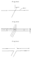
- Figs. 2 and 3 are plan views representing the roads for explaining the processes of forming the realistic road image.
- Fig. 2(a) shows the node N1 indicative of an intersection, and four links (including the link L1) extending from the node N1 and indicative of four road segments.
- the widths W of the road segments are determined on the basis of the aforementioned road width data, thereby making it possible to derive the profiles of the roads segments as shown in Fig. 2(b).
- the unnecessary lines and dots shown in Fig. 2(b) are eliminated in order to derive the realistic road image shown in Fig. 2(c).
- sidewalks having widths t are added to the realistic road image as shown in Fig. 3(a), and then pedestrian crossings and center lines are also added to the realistic road image as shown in Fig. 3(b).
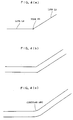
- the realistic road image derived on the basis of the links L2 and L3 and the node N2 is shown in Fig. 4(b).
- the road profile shown in Fig. 4(b) however is unnatural in comparison with the profile of the actual road, since the road profile shown in Fig. 4(b) is formed by merely straight lines.
- a smoothing process is carried out in order to smooth the corners of the roads.
- the profile of the corner of the road is defined by curved lines such as circular arcs as shown in Fig. 4(c).
- the realistic road image is formed in such a manner that the roads formed on the basis of the links L4 and L5 are connected to each other by means of a road segment having a taper profile portion as shown in Figs. 5(c).
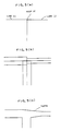
- the aforementioned smoothing process are carried out in order to smoothly connect the lines forming the road profiles, since the realistic road image shown in Fig. 6(a) is unnatural in comparison with the actual intersection.
- another smoothing process is carried out in order to cut the corner of each of the blocks enclosed by sidewalks, respectively.
- the road data are calculated in such a manner that each of the sidewalks has a width of 1.5 meters and is flush with the road or in such a manner that each of the sidewalks has a width of 3 meters and has sidewalk surface higher than the road surface by 20 centimeters.
- the background data includes architecture data indicative of architectures such as buildings and dwelling houses, traffic light data indicative of traffic lights, road sign data indicative of road signs, guardrail data indicative of guardrails and, tree and shrub data indicative of trees and shrubs.
- the width, the depth and the height of each of the buildings can be varied within predetermined ranges, respectively, each having a predetermined standard value and defined by a predetermined maximum value and a predetermined minimum value.
- the width, the depth and the height of each of the buildings are determined on the basis of the random numbers in such a manner as to be within the predetermined ranges, respectively.
- the positions of the buildings are determined in such a manner that each of the buildings is positioned along the road.
- the number of the buildings positioned along one road are determined in response to the length of the link forming the road.
- the architecture data include dwelling house data indicative of several kinds of the dwelling house.
- the dwelling houses are similarly positioned along the road, and the number of each of the dwelling houses are similarly determined in response to the length of the link forming the road.
- the width A of the building is determined by 1 meter on the basis of the random numbers in such a manner as to be within a range from 20 meters to the length of the link L6.
- the depth B of the building is determined by 1 meter on the basis of the random numbers in such a manner as to be within a range from 20 to 50 meters.
- the height of the building is determined by 1 mater on the basis of the random numbers in such a manner as to be within a range from 30 to 80 meters.
- the color used for painting the building is selected from predetermined eight colors on the basis of the random numbers.
- the design of building is selected from predetermined two designs on the basis of the random numbers.
- the distance M between the architecture and the road defined by the link L6, and the distance M between the architecture and the alternate long and short dash line passing the end of the link L6 are determined, for example, to be 10 meters.
- the distances M may exceed half of the width of the road defined by the link L6.
- the aforementioned determination of the distances M sometimes results in the fact that the image of the building is overlapped with the image of the another road. For this reason, it is necessary that the distance between the architecture and the alternate long and short dash line passing the end of the link L6 should be represented by ( M + N ) instead of M.
- a plurality of architectures are positioned in the road image having a plurality of corners within a narrow area, it is necessary that attention should be paid to the overlap of the architectures.
- the architectures are positioned along the cranked road defined by a plurality of links including the link L7 as shown in Fig. 8(a)
- the angles ⁇ 1 and ⁇ 2 shown in Fig. 8(b) between the link L7 and the adjoining links are calculated, and then the size of the architecture shown in Fig. 8(c) is determined on the basis of the random numbers in view of the calculated angles ⁇ 1 and ⁇ 2.
- Fig. 8(a) the angles ⁇ 1 and ⁇ 2 shown in Fig. 8(b) between the link L7 and the adjoining links are calculated, and then the size of the architecture shown in Fig. 8(c) is determined on the basis of the random numbers in view of the calculated angles ⁇ 1 and ⁇ 2.
- two architectures are positioned in the neighborhood of the end of the link L7 so as to be opposite to each other through the road defined the link L7 under the condition that the aforementioned distances M are equal to 0.
- the next architectures are similarly positioned in the neighborhood of the end of the next link as shown in Fig. 8(e). If, however, one of the next architectures and one of the previous architectures are overlapped with each other in part, the next architecture is eliminated from the road image as shown in Fig. 8(e).
- the traffic lights for the vehicles are positioned at the specified intersections and each periodically indicates red, amber and green.
- the traffic lights for the pedestrians are positioned at the pedestrian crossing in the neighborhood of the specified intersections and each periodically indicates red and green.
- the road signs are positioned at the specified intersections.
- the trees and shrubs, and the guardrails are positioned along the specified roads.
- the sky of the background are painted in sky blue.
- the color of the open space between the architectures in the background is predetermined.
- the height of the view point in the animation is similar to that (for example 1.2 meters) of the eyes of the driver on the driver's seat. If the width of the vehicle is 1.6 meters, the view point in the animation is positioned at the right side of the center of the vehicle in such a manner as to be remote from the center by 0.4 meters.
- the angles in the view point of the animation between two planes defining the horizontal visual field and between two planes defining the vertical visual field are 140 degrees and 100 degrees, respectively.
- the vehicle in the animation travels on the center of the left lane of the center line as shown in Fig. 9. As will be understood from the diagram shown in Fig. 10, the vehicle in the animation slows down during a travel of a predetermined distance a before a rapid variation of the advance direction of the vehicle. On the other hand, the vehicle in the animation speeds up during a travel of the predetermined distance a after the rapid variation of the advance direction of the vehicle.
- the road data and background data are calculated thorough the three-dimensional computer graphics, thereby making it possible to produce the animation having the series of the road drawings to be watched from the driver's seat.
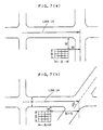
- a road map shown in Fig. 11 and formed by the nodes and the links is derived from the road map data base device 1. If the vehicle is to travel from a position A to a position B , the travel route data indicative of the travel route (referred to arrows in Fig. 11) between the positions A and B are fed to the calculator 4 in order to calculate the road data and the background data on the basis of the travel route data by the foregoing processes, thereby making it possible to produce the animation having the series of road drawings to be watched from the driver's seat.
- One of the road drawings is shown in Fig.
- the road drawing shown in Fig. 12 includes center lines, sidewalks and pedestrian crossings. The corners of the intersection are defined by curved lines in the road drawing. Additionally, the road drawing includes the traffic lights, the building and the tree positioned in the neighborhood of the intersection.
- the display unit opens first and second windows on its own screen showing the road drawing and displays the navigational guidance derived from the navigation apparatus 2 so as to show the travel road and the advance direction of the vehicle to the driver.
- the first window shows a road map area similar to the rectangular area R covering the position C as shown in Fig. 11 and indicates by a predetermined mark the current position of the vehicle on the road map.
- the second window opened in the first window indicates the advance direction in which the vehicle is to advance at the intersection.
- the color of each of the roads forming the travel route may be determined in such a manner as to be different from that of the other roads in the road map.
- the buildings, the traffic lights and the like are not shown in the navigational guidance.
- the navigational guidance is shown in the first and second windows in such a manner that the vehicle advances in the perpendicular direction in Fig. 12. However, the north in the road map may correspond to the upper part of the windows.
- the vehicle After the advance direction is indicated in the second window, the vehicle is to turn according to the indicated advance direction, for example, to the right as shown in Fig. 12. After, therefore, the vehicle turns according to the indication, the second window is unnecessary and thus closed.
- the mark indicative of the current position of the vehicle shown in the first window is moved to the next link synchronously with the movement of the vehicle.
- the vehicle in the animation shown on the screen of the display unit turns to the right at the intersection.
- the navigational guidance shown in the first window in Fig. 12 shows the rectangular area R shown in Fig. 11.
- the navigational guidance may indicate a large area, for example, the whole area in Fig. 11 instead of or in addition to the rectangular area R .
- the road data and the background data are automatically calculated by the calculator 4, thereby making it possible to produce and display the animation.
- the background data indicative of the backgrounds in the animation are calculated on the basis of random numbers, thereby making it possible to cause the backgrounds in the animation to be full of variety.
- the navigational guidance derived by the navigation apparatus 2 is displayed synchronously with the animation. If, therefore, the animation producing system comprising the navigation apparatus is not mounted on the vehicle, the accuracy of the navigational guidance generated by the navigation apparatus 2 can be appreciated by the animation.
- the animation producing system comprises the navigation apparatus.
- the navigation apparatus of the present embodiment forms the animation producing apparatus comprising a display unit designed to display the animation at real time during the actual travel of the vehicle, or display the animation during the confirmation of the travel route before the actual travel.
- the navigation apparatus forming the animation producing apparatus is mounted on a vehicle and designed to produce an animation having a series of road drawings to be watched from the driver's seat of the vehicle.
- the road drawings are formed on the basis of road data and background data obtained through three-dimensional computer graphics and are varied during a travel on an optimum travel route from the current position of the vehicle from a destination.
- the road data and the background data are indicative of roads and backgrounds, respectively, shown in the animation.
- Fig. 13 is a block diagram representing the navigation apparatus which comprises a distance sensor 11 for detecting the travel distance of the vehicle, a geomagnetic sensor 12 for detecting the travel direction of the vehicle, a shift sensor 13 for detecting the forward and backward movement of the vehicle, a locator 15 deriving signals from the sensors 11, 12 and 13, an oscillation gyro sensor 16 for detecting the turn angle of the vehicle and feeding its own output signal to the locator 15, controller 17 forming the center of the control of the navigation apparatus, a memory driver 18 for reading out data from a map indication data disk D1 and a road map data disk D2, a display unit 22 for displaying the animation and the navigational guidance, a touch switch unit 23 including a plurality of touch switches, a phonetically indicating generator 25 for phonetically indicating the navigational guidance to the driver, a beacon receiver 27 for receiving beacon information from beacon antennas, and a global positioning system (hereinlater simply referred to as "GPS”) receiver 29 for receiving electric waves from a plurality of GPS
- the map indication data disk D1 stores road map indication data indicative of road maps to be indicated in the display unit 22.
- the road map indication data are derived on the basis of a map data base providing maps drawn to a scale of 1/2,500 and include data indicative of roads, data indicative of place-names, data indicative of famous facilities, data indicative of railways, and data indicative of rivers.
- the road map data disk D2 stores road map data indicative of a road map (including highways and streets) divided into a plurality of mesh sections, and including node data indicative of nodes defined by coordinates and formed by intersections, corners and ends of roads, link data indicative of links each connecting two of the nodes to define a road segment, and road width data indicative of the widths of the road segments.
- the node data are further indicative of nodes formed by the ends of the roads in a border between two of the mesh sections.
- the road map data further include data indicative of link numbers for designating the links, data indicative of the start address and the end address of each of links, data indicative of the travel needed time from the start address to the end address, data indicative of the lengths of the links, data indicative of classification of the road, data for specifying the one-way traffic roads, data indicative of "no turning to the right and the left", and data for specifying toll highways.
- the highways of the road map form a closed road network in the whole country.
- the locator 15 is designed to calculate the current position of the vehicle. Specifically, the variation amount of the travel direction is calculated by the locator 15 on the basis of the travel direction detected by the geomagnetic sensor 12 and the turn angle detected by the oscillation gyro sensor 16. At the same time, the movement distance of the vehicle is calculated by the locator 15 on the basis of the travel distance detected by the distance sensor 15 and the forward and backward movement detected by the shift sensor 13. If initial position data indicative of the initial position of the vehicle is inputted to the locator 15 before the start of the vehicle, the locator 15 can calculate the current position of the vehicle remote from the initial position.
- the locator 15 Based on the current vehicle position data, the locator 15 also calculates traveled route data indicative of the route which the vehicle has traveled, and compares the route pattern defined by the traveled route data with the road patterns stored in the road map data disk D2 (by a so-called map matching method), thereby making it possible to determine a most probable road which the vehicle is traveling at present and recalculate the current vehicle position indicative of the current position of the vehicle on the determined road.
- the current vehicle position data recalculated through the map matching method are fed to the controller 17 functioning as the center of the control of the navigation apparatus.
- the controller 17 comprises a CPU (Central Processing Unit), a ROM (Read Only Memory) and a RAM (Random Access Memory), and is electrically connected to the locator 15, the memory driver 18, the graphic generator 24, the display unit 22, the touch switch unit 23 and the phonetically indicating generator 25.
- the controller 17 controls the memory driver 18 on the basis of the current vehicle position data calculated by the locator 15.
- the road map indication data prepared for indication and covering the current position of the vehicle are read out from the map indication data disk D1 and fed to the controller 17 by the memory driver 18 in response to the control signal outputted from the controller 17.
- the current vehicle position data calculated by the locator 15 and the road map indication data read out by the memory driver 18 are fed to the display unit 22 from the controller 17, so that the road map and the current vehicle position can be displayed on the screen of the display unit 22 in such a manner that the current position of the vehicle is shown on the road map by a predetermined mark.
- the memory driver 18 further reads out from the road map data disk D2 road map data used during the calculation of the optimum travel route between the current vehicle position and the destination, and feeds the road map data to the controller 17 to determine the coordinates defining the optimum travel route on the road map, thereby making it possible to have the display unit 22 display the optimum travel route.
- the controller 17 is electrically connected to the beacon receiver 27 designed to receive beacon information transmitted from beacon antennas placed on the road sides.
- the beacon information include position information and road information (indicative of the names of the intersections and the places to which the roads leads) and are fed to the controller 17 so as to be indicated on the screen of the display unit 22, thereby making it possible to inform the driver of the beacon information.
- the GPS receiver 29 electrically connected to the locator 15 is an optional equipment. If the navigation apparatus comprises the GPS receiver 29, signals transmitted from the GPS satellites are fed to the locator 15 through the GPS receiver 29, so that locator 15 can detect the accurate current travel direction of the vehicle and the accurate current position of the vehicle.
- Fig. 14 is a block diagram representing the controller 17 which comprises a map data controlling unit 31 for reading out the specified road map indication data and the road map data from the road map indication data disks D1 and the road map data disk D2, respectively, through the memory driver 18, an input processing unit 32 for converting the operations of the touch switches of touch switch unit 23 into signals, an optimum route calculation processing unit 33 for calculating the optimum travel route data on the basis of the destination data, the current vehicle position data derived from locator 15, and the link and node data, a main memory 34 for storing various data, a three-dimensional computer graphics processing unit 35 for three-dimensionally processing various image data, and a travel route indication controlling unit 36 for controlling the indication of the display unit 22.
- a map data controlling unit 31 for reading out the specified road map indication data and the road map data from the road map indication data disks D1 and the road map data disk D2, respectively, through the memory driver 18, an input processing unit 32 for converting the operations of the touch switches of touch switch unit 23 into signals, an optimum route calculation processing unit
- the road data and the background data covering the optimum travel route are calculated by the three-dimensional computer graphics processing unit 35 forming the center of the animation processing in order to derive the series of road drawings to be three-dimensionally watched from the driver's seat.
- the road data in this embodiment are similar to those calculated by the calculator 4 of the aforementioned embodiment shown in Fig. 1 and can be calculated according to processes similar to those of the aforementioned embodiment explained with reference to Figs. 2 to 6. The processes are simply described hereinafter.
- the map data controlling unit 31 is accessed by the input processing unit 32 for reading out the road map indication data from the map indication data disk D1. Then, the widths of the roads forming the optimum travel route and the widths of the other roads shown in the road drawings are determined.
- the smoothing processes are carried out in order to smooth the corners of the intersections on the optimum travel route.
- the center lines, sidewalks and pedestrian crossings are added to the road drawings.
- the background data are calculated according to processes similar to those of the aforementioned embodiment explained with reference to Figs 7 to 10.
- the background data including the architecture data and road sign data are automatically derived on the basis of the random numbers.
- the background data may be derived on the basis of the road map data stored in the road map data disk D2.
- the road map data includes background element data including architecture data indicative of architectures, traffic light data indicative of traffic lights, road sign data indicative of road signs, guardrail data indicative of guardrails, tree and shrub data indicative of trees and shrubs, and geographical feature data indicative of geographical features.
- the architectures data include, for example, data indicative of positions, shapes and colors of facilities such as famous buildings.
- the geographical features represents, for example, mountains, parks and bridges.
- the background data may be derived on the basis of both the calculation data based on the random numbers and the store data based on road map data stored in the road map data disk D2.
- the road drawing data are indicative of the series of the road drawings to be watched from the driver's seat during the travel, and are calculated on the basis of the road data, the background data and the actual travel speed of the vehicle calculated by the locator 15 by the three-dimensional computer graphics. Then, the road drawing data are fed to the graphic generator 24 in order to convert the road drawing data into data suitable for indication in the display unit 22, thereby making it possible to have the display unit 22 display the animation synchronous with the actual travel of the vehicle.
- the animation formed by the series of road drawings to be watched from the driver's seat during the travel between the current vehicle position and the destination are displayed on the screen of the display unit 22 at real time during the actual travel between the current vehicle position and the destination. Therefore, the animation displayed by the display unit 22 is useful not only for leading the driver to the destination but also for pleasing the eyes of the passengers.
- the optimum travel route and the current position of the vehicle are derived by the travel route calculation processing unit 33 and the locator 15, respectively.
- the optimum travel route and the current vehicle position may be indicated with the animation as shown in Fig. 12, thereby making it possible to easily lead the driver to the destination.
- the animation is displayed on the screen of the display unit 22, and the navigational guidance is indicated in the windows opened on the screen.
- the animation may be displayed in the windows opened on the screen of the display unit 22, and the navigational guidance may be displayed on the screen.
- the animation may be displayed on the screen of the display unit 22 while the vehicle travels from a first position approaching toward each of the intersections on the optimum travel route to a second position departing from the intersection under condition that the navigational guidance is indicated on the screen or in the window at all times, thereby making it possible to have the driver identify the marked architecture such as a gas station in the neighborhood of each of the intersections.
- the advance direction of the vehicle may be phonetically indicated by the phonetically indicating generator 25 before the vehicle reaches through each of the intersections, thereby making it possible to certainly lead the driver to the destination.
- the optimum travel route is calculated when the driver inputs the destination to the navigation apparatus through the touch switch unit 23, so that the animation can be produced and displayed before the start of the vehicle. If the animation is displayed at rapid advance speed before the start of the vehicle, the driver can simulate the travel on the optimum travel in a short time. In the case which the background data calculated on the basis of the background element data stored in the road map data disk D2, the driver can previously commit the background watched during the actual travel to memory.
Abstract
Description
- The present invention relates to a method of and an apparatus for producing an animation having a series of road drawings to be watched from a driver's seat. The road drawings are obtained on the basis of road map data through three-dimensional computer graphics.
- There have been so far proposed a method of and an apparatus for producing an animation having a series of road drawings to be watched from a driver's seat of a vehicle. If such an animation is displayed on the screen of a display unit placed in a playing room, the animation is useful for a driving simulation in the room. For example, the animation can be produced by executing a computer graphics software.
- When, however, the animation is produced by executing programs of such a computer graphics software, it is necessary that an animator should imaginatively derive road data (including data indicative of a pattern of a travel route, data indicative of the shapes of the roads forming the travel route, and data indicative of the widths of the roads) indicative of the road drawings forming the animation, thereby having the animator extremely expend his labor and time. In addition, the variety of the travel route pattern is so restricted that the animation loses its popularity soon.
- The present invention has been made to overcome the foregoing problems in the prior art, and a first object of the present invention is to provide a method of producing an animation having a series of road drawings showing roads which are in existence.
- It is a second object of the present invention to provide an apparatus capable of displaying the animation in such a manner that the animation is synchronous with the actual vehicle travel.
- The foregoing first object of the present invention can be achieved by providing a method of producing an animation having a series of road drawings to be watched from a driver's seat of a vehicle during a travel between two predetermined positions in a road map, the road drawings being formed on the basis of road data obtained through three-dimensional computer graphics, and the road data being indicative of roads shown in the animation, comprising the steps of: preparing travel route data providing means for providing travel route data indicative of a travel route between the predetermined positions, and road map data storing means for storing road map data including node data indicative of nodes formed by intersections, corners and ends of roads, link data indicative of links each connecting two of the nodes to define a road segment, and road width data indicative of the widths of the road segments, selecting from the road map data storing means the road map data covering the travel route based on the provided travel route data, and calculating the road data on the basis of the selected road map data to produce the animation in such a manner that the roads are three-dimensionally shown in the road drawings.
- In addition, the foregoing first object of the present invention can be achieved by providing a method of producing an animation having a series of road drawings to be watched from a driver's seat of a vehicle during a travel between two predetermined positions in a road map, the road drawings being formed on the basis of road data and background data obtained through three-dimensional computer graphics, and the road data and the background data being indicative of roads and backgrounds, respectively, shown in the animation, comprising the steps of: preparing travel route data providing means for providing travel route data indicative of a travel route between the predetermined positions, road map data storing means for storing road map data including node data indicative of nodes formed by intersections, corners and ends of roads, link data indicative of links each connecting two of the nodes to define a road segment and road width data indicative of the widths of the road segments, and random number generating means for generating random numbers, selecting from the road map data storing means the road map data covering the travel route based on the travel route data, calculating the road data on the basis of the selected road map data to produce the animation in such a manner that the roads are three-dimensionally shown in the road drawings, and calculating the background data on the basis of the generated random numbers to produce the animation in such a manner that the backgrounds are three-dimensionally shown in the road drawings.
- The foregoing second object of the present invention can be achieved by providing an apparatus for producing an animation having a series of road drawings to be watched from a driver's seat of a vehicle during a travel from the current position of the vehicle to a destination, the road drawings being formed on the basis of road data and background data obtained through three-dimensional computer graphics, and the road data and the background data being indicative of roads and backgrounds, respectively, shown in the animation, comprising: vehicle position detecting means for detecting the current position of the vehicle, optimum travel route data calculating means for calculating optimum travel route data indicative of an optimum travel route between the current position of the vehicle and the destination, road map data storing means for storing road map data to be referred to during the travel on the optimum travel route, road map data selecting means for selecting from the road map data storing means the road map data covering the optimum travel route, road data calculating means for calculating the road data on the basis of the selected road map data to produce the animation in such a manner that the roads are three-dimensionally shown in the road drawings, background data calculating means for calculating the background data to produce the animation in such a manner that the backgrounds are three-dimensionally shown in the road drawings, and animation displaying means for displaying the produced animation.
- The features and advantages of a method of and an apparatus for producing an animation having a series of road drawings to be watched from a driver's seat of a vehicle in accordance with the present invention will be more clearly understood from the following description take in conjunction with the accompanying drawings in which:
- Fig. 1 is a schematic block diagram of an animation producing system employing an animation producing method according to the present invention;
- Figs. 2(a) to 2(c) are explanatory illustrations showing processes of forming a realistic road image from nodes and links;
- Figs. 3(a) and 3(b) are explanatory illustrations showing processes of forming a realistic road image after the processes shown in Fig. 2(c);
- Figs. 4(a) to 4(c) are explanatory illustrations showing road profile smoothing processes in the case that two links extend from one node in different directions;
- Figs. 5(a) to 5(c) are explanatory illustrations showing intersection profile smoothing processes in the case that links representing different roads in width extend from one node;
- Figs. 6(a) and 6(b) are explanatory illustrations showing processes of smoothing an intersection profile and sidewalk profiles by curved lines and the like.
- Figs. 7(a) and 7(b) are explanatory illustrations showing processes of positioning an architecture on the basis of the random numbers;
- Figs. 8(a) to 8(e) are explanatory illustrations showing processes of eliminating an architecture overlapped with the previous architecture.
- Fig. 9 is an explanatory illustration showing the travel position while the vehicle passing through an intersection:
- Fig. 10 is a diagram showing the vehicle speed in the animation while the vehicle passes through intersections and corners;
- Fig. 11 is a diagram showing a road map defined by the links and nodes;
- Fig. 12 is a diagram showing a road drawings partially forming the animation;
- Fig. 13 is a block diagram showing a navigation apparatus comprising an animation producing apparatus according to the present invention; and
- Fig. 14 is a block diagram showing the controller shown in Fig. 13.
- An embodiment of an animation producing system adopting an animation producing method according to the present invention will be hereinlater described with reference to Figs. 1 to 12 of the drawings.
- The animation produced by the animation producing system has a series of road drawings to be watched from a driver's seat of a vehicle during a travel between two predetermined positions in a road map. The road drawings are formed on the basis of road data and background data obtained through three-dimensional computer graphics. The road data and the background data are indicative of roads and backgrounds, respectively, shown in the animation, and integrally forms road drawing data indicative of the road drawings.
- Fig. 1 is a block diagram showing the animation producing system which comprises a road map data base device 1, a
navigation apparatus 2, aflexible disk 3, a calculator 4, road drawing forming equipment 5, a video tape recorder (hereinlater simply referred to as "VTR") 6, and an animationdata base device 7. - The
flexible disk 3 stores and provides travel route data indicative of a travel route between the aforementioned predetermined positions, i.e., to be traveled by the vehicle. Additionally, the travel route data includes travel speed data indicative of the travel speed of the vehicle in the animation. The advance speed of the animation is determined in such a manner as to be varied in response to the travel speed of the vehicle. - The road map data base device 1 such as for example a CD-ROM (Compact Disc of Read Only Memory) stores road map data formed by the whole country map data base providing maps drawn to a scale of for example 1/2,500. The road map data are indicative of road maps formed by a plurality of nodes and a plurality of links. In other words, the road map data include node data indicative of nodes formed by intersections, corners and ends of roads, link data indicative of links each connecting two of the nodes to define a road segment and road width data indicative of the widths of the road segments. The positions of the nodes are represented by coordinates. Each of the links is to be represented as a vector defined by coordinates of two nodes connected by the link.
- The
navigation apparatus 2 is adapted to generate leading indication data indicative of the travel route, the current position of the vehicle and the advance direction in which the vehicle is to advance at each of the intersections on the travel route. Based on the leading indication data, the travel route, the current position and the advance direction of the vehicle are displayed as the navigational guidance described hereinafter on a screen of a display unit not shown. In addition, the leading indication data are used for phonetically indicating the advance direction when the vehicle approaches toward each of the intersections. - A conventional navigation apparatus comprises a position detecting equipment for detecting the current position of the vehicle, and a travel route calculating equipment for calculating travel route data indicative of the optimum travel route. The vehicle position detecting equipment comprises a direction sensor for detecting the travel direction of the vehicle and a speed sensor for detecting the travel speed of the vehicle. The current position of the vehicle is derived on the basis of the outputs of the direction sensor and the speed sensor. Additionally, the conventional navigation apparatus reads out the road map data covering the current position of the vehicle from a map data base device so as to have a display unit displaying the current position of the vehicle and the road map covering the current position of the vehicle in such a manner that the current position of the vehicle is overlaid upon the road map. In the conventional navigation apparatus, therefore, the foregoing leading indication data are calculated on the basis of the detected current position of the vehicle and the calculated optimum travel route. Such a conventional navigation apparatus is generally known and disclosed in, for example, Japanese patent laid-open publication No. 2-6713.
- In the present embodiment, however, the
navigation apparatus 2 is designed to input from, for example, the calculator 4 the position data indicative of the provisional current position of the vehicle and the travel route data provided from theflexible disk 3 on the assumption that the vehicle is traveling the travel route based on the provided travel route data. Thenavigation apparatus 2 calculates the leading indication data on the basis of the position data indicative of the provisional current position the vehicle and the travel route data provided from theflexible disk 3. - The calculator 4 is electrically connected to the road map data base device 1, the
navigation apparatus 2, theflexible disk 3, the road drawing forming equipment 5 and the animationdata base device 7, and functions as a random number generator. In the calculator 4, the road data and the background data are calculated by, for example, executing programs of a three-dimensional computer graphics software placed on the market. - The processes of producing the animation will be described hereinafter. First, the road map data covering the travel route derived from the
flexible disk 3 are selected and read out by the calculator 4 from the road map data base device 1. Based on the selected road map data, the road data are calculated by the calculator 4 in such a manner that the roads are three-dimensionally shown in the road drawings. Then, the background data are calculated by the calculator 4 on the basis of the random numbers in such a manner that the backgrounds are three-dimensionally shown in the road drawings. - The road drawing data formed by the road data and the background data calculated by the calculator 4 are fed to the road drawing forming equipment 5 or the animation
data base device 7. - When the road drawing data including the road data and the background data calculated by the calculator 4 are processed by the road drawing forming equipment 5, the series of road drawings are generated, thereby making it possible to produce the animation in the NTSC (National Television System Committee) formula. The produced animation is recorded in the
VTR 6. - The processes of calculating the aforementioned road data will be more specifically described hereinafter.
- The road data are calculated on the basis of the foregoing selected road map data in such a manner that the road data are indicative of realistic road images each having appropriate width. If necessary, the road data are further calculated in such a manner that sidewalks are added to the realistic road image.
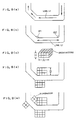
- Figs. 2 and 3 are plan views representing the roads for explaining the processes of forming the realistic road image. Fig. 2(a) shows the node N1 indicative of an intersection, and four links (including the link L1) extending from the node N1 and indicative of four road segments. The widths W of the road segments are determined on the basis of the aforementioned road width data, thereby making it possible to derive the profiles of the roads segments as shown in Fig. 2(b). The unnecessary lines and dots shown in Fig. 2(b) are eliminated in order to derive the realistic road image shown in Fig. 2(c). Additionally, sidewalks having widths t are added to the realistic road image as shown in Fig. 3(a), and then pedestrian crossings and center lines are also added to the realistic road image as shown in Fig. 3(b).
- If two links extend from one node in different directions, i.e., the links L2 and L3 extend from the node N2 as shown in Fig. 4(a), the realistic road image derived on the basis of the links L2 and L3 and the node N2 is shown in Fig. 4(b). The road profile shown in Fig. 4(b) however is unnatural in comparison with the profile of the actual road, since the road profile shown in Fig. 4(b) is formed by merely straight lines. In this case, a smoothing process is carried out in order to smooth the corners of the roads. As a result, the profile of the corner of the road is defined by curved lines such as circular arcs as shown in Fig. 4(c).
- If a plurality of links representing roads different in width extend from one node, i.e., the links L4 and L5 extend from the node N3 as shown in Figs. 5(a) and 5(b), the realistic road image is formed in such a manner that the roads formed on the basis of the links L4 and L5 are connected to each other by means of a road segment having a taper profile portion as shown in Figs. 5(c).
- In the processes of forming the realistic road image representing an intersection, the aforementioned smoothing process are carried out in order to smoothly connect the lines forming the road profiles, since the realistic road image shown in Fig. 6(a) is unnatural in comparison with the actual intersection. In addition, another smoothing process is carried out in order to cut the corner of each of the blocks enclosed by sidewalks, respectively. After the foregoing smoothing processes, the realistic road image shown in Fig. 6(b) are derived.
- When the sidewalks are added to the realistic road image, the road data are calculated in such a manner that each of the sidewalks has a width of 1.5 meters and is flush with the road or in such a manner that each of the sidewalks has a width of 3 meters and has sidewalk surface higher than the road surface by 20 centimeters.
- The processes of calculating the background data on the basis of the random numbers will be more specifically described hereinlater.
- The background data includes architecture data indicative of architectures such as buildings and dwelling houses, traffic light data indicative of traffic lights, road sign data indicative of road signs, guardrail data indicative of guardrails and, tree and shrub data indicative of trees and shrubs.
- If the background comprises the images of the buildings, the width, the depth and the height of each of the buildings can be varied within predetermined ranges, respectively, each having a predetermined standard value and defined by a predetermined maximum value and a predetermined minimum value. The width, the depth and the height of each of the buildings are determined on the basis of the random numbers in such a manner as to be within the predetermined ranges, respectively. On the other hand, the positions of the buildings are determined in such a manner that each of the buildings is positioned along the road. In addition, the number of the buildings positioned along one road are determined in response to the length of the link forming the road. The architecture data include dwelling house data indicative of several kinds of the dwelling house. The dwelling houses are similarly positioned along the road, and the number of each of the dwelling houses are similarly determined in response to the length of the link forming the road.
- If, for example, the length of the link is less than 120 meters, there is no architecture positioned along the road defined the link. If the length of the link exceeds 120 meters, at least one architecture is positioned along the roads. In Fig. 7(a), the width A of the building is determined by 1 meter on the basis of the random numbers in such a manner as to be within a range from 20 meters to the length of the link L6. The depth B of the building is determined by 1 meter on the basis of the random numbers in such a manner as to be within a range from 20 to 50 meters. The height of the building is determined by 1 mater on the basis of the random numbers in such a manner as to be within a range from 30 to 80 meters. The color used for painting the building is selected from predetermined eight colors on the basis of the random numbers. The design of building is selected from predetermined two designs on the basis of the random numbers.
- If the architecture is positioned along the road defined by the link L6 shown in Fig. 7(a) in the neighborhood of the intersection at which the road intersects with another road at a right angle, the distance M between the architecture and the road defined by the link L6, and the distance M between the architecture and the alternate long and short dash line passing the end of the link L6 are determined, for example, to be 10 meters. Preferably, the distances M may exceed half of the width of the road defined by the link L6.
- If, however, the architecture is positioned along the road defined by the link L6 shown in Fig. 7(b) in the neighborhood of the intersection at which the road intersects with another road at the acute angle ϑ, the aforementioned determination of the distances M sometimes results in the fact that the image of the building is overlapped with the image of the another road. For this reason, it is necessary that the distance between the architecture and the alternate long and short dash line passing the end of the link L6 should be represented by (M + N) instead of M. The distance N, for example, is determined by a formula represented as follows.

- When, additionally, a plurality of architectures are positioned in the road image having a plurality of corners within a narrow area, it is necessary that attention should be paid to the overlap of the architectures. If, for example, the architectures are positioned along the cranked road defined by a plurality of links including the link L7 as shown in Fig. 8(a), the angles α1 and α2 shown in Fig. 8(b) between the link L7 and the adjoining links are calculated, and then the size of the architecture shown in Fig. 8(c) is determined on the basis of the random numbers in view of the calculated angles α1 and α2. As shown in Fig. 8(d), two architectures are positioned in the neighborhood of the end of the link L7 so as to be opposite to each other through the road defined the link L7 under the condition that the aforementioned distances M are equal to 0. The next architectures are similarly positioned in the neighborhood of the end of the next link as shown in Fig. 8(e). If, however, one of the next architectures and one of the previous architectures are overlapped with each other in part, the next architecture is eliminated from the road image as shown in Fig. 8(e).
- The traffic lights for the vehicles are positioned at the specified intersections and each periodically indicates red, amber and green. The traffic lights for the pedestrians are positioned at the pedestrian crossing in the neighborhood of the specified intersections and each periodically indicates red and green.
- The road signs are positioned at the specified intersections. The trees and shrubs, and the guardrails are positioned along the specified roads. The sky of the background are painted in sky blue. The color of the open space between the architectures in the background is predetermined.
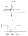
- The height of the view point in the animation is similar to that (for example 1.2 meters) of the eyes of the driver on the driver's seat. If the width of the vehicle is 1.6 meters, the view point in the animation is positioned at the right side of the center of the vehicle in such a manner as to be remote from the center by 0.4 meters. The angles in the view point of the animation between two planes defining the horizontal visual field and between two planes defining the vertical visual field are 140 degrees and 100 degrees, respectively. The vehicle in the animation travels on the center of the left lane of the center line as shown in Fig. 9. As will be understood from the diagram shown in Fig. 10, the vehicle in the animation slows down during a travel of a predetermined distance a before a rapid variation of the advance direction of the vehicle. On the other hand, the vehicle in the animation speeds up during a travel of the predetermined distance a after the rapid variation of the advance direction of the vehicle.
- According to the aforementioned processes, the road data and background data are calculated thorough the three-dimensional computer graphics, thereby making it possible to produce the animation having the series of the road drawings to be watched from the driver's seat.
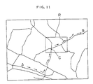
- Next, an example of the animation will be explained. If a certain area, for example, Edogawa-ku in Japan is selected, a road map shown in Fig. 11 and formed by the nodes and the links is derived from the road map data base device 1. If the vehicle is to travel from a position A to a position B, the travel route data indicative of the travel route (referred to arrows in Fig. 11) between the positions A and B are fed to the calculator 4 in order to calculate the road data and the background data on the basis of the travel route data by the foregoing processes, thereby making it possible to produce the animation having the series of road drawings to be watched from the driver's seat. One of the road drawings is shown in Fig. 12 and represents a street scene seen through the front window by the eyes of the driver on the driver's seat before the vehicle reaches the intersection defined by the position D in Fig. 11. The road drawing shown in Fig. 12 includes center lines, sidewalks and pedestrian crossings. The corners of the intersection are defined by curved lines in the road drawing. Additionally, the road drawing includes the traffic lights, the building and the tree positioned in the neighborhood of the intersection.
- The display unit opens first and second windows on its own screen showing the road drawing and displays the navigational guidance derived from the
navigation apparatus 2 so as to show the travel road and the advance direction of the vehicle to the driver. More specifically, the first window shows a road map area similar to the rectangular area R covering the position C as shown in Fig. 11 and indicates by a predetermined mark the current position of the vehicle on the road map. As shown in Fig. 12, the second window opened in the first window indicates the advance direction in which the vehicle is to advance at the intersection. The color of each of the roads forming the travel route may be determined in such a manner as to be different from that of the other roads in the road map. The buildings, the traffic lights and the like are not shown in the navigational guidance. The navigational guidance is shown in the first and second windows in such a manner that the vehicle advances in the perpendicular direction in Fig. 12. However, the north in the road map may correspond to the upper part of the windows. - After the advance direction is indicated in the second window, the vehicle is to turn according to the indicated advance direction, for example, to the right as shown in Fig. 12. After, therefore, the vehicle turns according to the indication, the second window is unnecessary and thus closed. On the other hand, the mark indicative of the current position of the vehicle shown in the first window is moved to the next link synchronously with the movement of the vehicle. At the same time, the vehicle in the animation shown on the screen of the display unit turns to the right at the intersection.
- In this embodiment, the navigational guidance shown in the first window in Fig. 12 shows the rectangular area R shown in Fig. 11. However, the navigational guidance may indicate a large area, for example, the whole area in Fig. 11 instead of or in addition to the rectangular area R.
- As will be understood from the aforementioned description, the road data and the background data are automatically calculated by the calculator 4, thereby making it possible to produce and display the animation. Particularly, the background data indicative of the backgrounds in the animation are calculated on the basis of random numbers, thereby making it possible to cause the backgrounds in the animation to be full of variety.
- In addition, the navigational guidance derived by the
navigation apparatus 2 is displayed synchronously with the animation. If, therefore, the animation producing system comprising the navigation apparatus is not mounted on the vehicle, the accuracy of the navigational guidance generated by thenavigation apparatus 2 can be appreciated by the animation. - An embodiment of an animation producing apparatus according to the present invention will be described hereinlater. In the aforementioned embodiment shown in Fig. 1, the animation producing system comprises the navigation apparatus. On the other hand, the navigation apparatus of the present embodiment forms the animation producing apparatus comprising a display unit designed to display the animation at real time during the actual travel of the vehicle, or display the animation during the confirmation of the travel route before the actual travel.
- The navigation apparatus forming the animation producing apparatus is mounted on a vehicle and designed to produce an animation having a series of road drawings to be watched from the driver's seat of the vehicle. The road drawings are formed on the basis of road data and background data obtained through three-dimensional computer graphics and are varied during a travel on an optimum travel route from the current position of the vehicle from a destination. The road data and the background data are indicative of roads and backgrounds, respectively, shown in the animation.
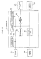
- Fig. 13 is a block diagram representing the navigation apparatus which comprises a
distance sensor 11 for detecting the travel distance of the vehicle, ageomagnetic sensor 12 for detecting the travel direction of the vehicle, ashift sensor 13 for detecting the forward and backward movement of the vehicle, alocator 15 deriving signals from thesensors oscillation gyro sensor 16 for detecting the turn angle of the vehicle and feeding its own output signal to thelocator 15,controller 17 forming the center of the control of the navigation apparatus, amemory driver 18 for reading out data from a map indication data disk D1 and a road map data disk D2, adisplay unit 22 for displaying the animation and the navigational guidance, atouch switch unit 23 including a plurality of touch switches, a phonetically indicatinggenerator 25 for phonetically indicating the navigational guidance to the driver, abeacon receiver 27 for receiving beacon information from beacon antennas, and a global positioning system (hereinlater simply referred to as "GPS")receiver 29 for receiving electric waves from a plurality of GPS satellites revolving around the earth. - The map indication data disk D1 stores road map indication data indicative of road maps to be indicated in the
display unit 22. The road map indication data are derived on the basis of a map data base providing maps drawn to a scale of 1/2,500 and include data indicative of roads, data indicative of place-names, data indicative of famous facilities, data indicative of railways, and data indicative of rivers. - The road map data disk D2 stores road map data indicative of a road map (including highways and streets) divided into a plurality of mesh sections, and including node data indicative of nodes defined by coordinates and formed by intersections, corners and ends of roads, link data indicative of links each connecting two of the nodes to define a road segment, and road width data indicative of the widths of the road segments. The node data are further indicative of nodes formed by the ends of the roads in a border between two of the mesh sections. The road map data further include data indicative of link numbers for designating the links, data indicative of the start address and the end address of each of links, data indicative of the travel needed time from the start address to the end address, data indicative of the lengths of the links, data indicative of classification of the road, data for specifying the one-way traffic roads, data indicative of "no turning to the right and the left", and data for specifying toll highways. In view of the characteristics of the map data base, the highways of the road map form a closed road network in the whole country.
- The
locator 15 is designed to calculate the current position of the vehicle. Specifically, the variation amount of the travel direction is calculated by thelocator 15 on the basis of the travel direction detected by thegeomagnetic sensor 12 and the turn angle detected by theoscillation gyro sensor 16. At the same time, the movement distance of the vehicle is calculated by thelocator 15 on the basis of the travel distance detected by thedistance sensor 15 and the forward and backward movement detected by theshift sensor 13. If initial position data indicative of the initial position of the vehicle is inputted to thelocator 15 before the start of the vehicle, thelocator 15 can calculate the current position of the vehicle remote from the initial position. - Based on the current vehicle position data, the
locator 15 also calculates traveled route data indicative of the route which the vehicle has traveled, and compares the route pattern defined by the traveled route data with the road patterns stored in the road map data disk D2 (by a so-called map matching method), thereby making it possible to determine a most probable road which the vehicle is traveling at present and recalculate the current vehicle position indicative of the current position of the vehicle on the determined road. - The current vehicle position data recalculated through the map matching method are fed to the
controller 17 functioning as the center of the control of the navigation apparatus. Thecontroller 17 comprises a CPU (Central Processing Unit), a ROM (Read Only Memory) and a RAM (Random Access Memory), and is electrically connected to thelocator 15, thememory driver 18, thegraphic generator 24, thedisplay unit 22, thetouch switch unit 23 and the phonetically indicatinggenerator 25. Thecontroller 17 controls thememory driver 18 on the basis of the current vehicle position data calculated by thelocator 15. The road map indication data prepared for indication and covering the current position of the vehicle are read out from the map indication data disk D1 and fed to thecontroller 17 by thememory driver 18 in response to the control signal outputted from thecontroller 17. The current vehicle position data calculated by thelocator 15 and the road map indication data read out by thememory driver 18 are fed to thedisplay unit 22 from thecontroller 17, so that the road map and the current vehicle position can be displayed on the screen of thedisplay unit 22 in such a manner that the current position of the vehicle is shown on the road map by a predetermined mark. - The
memory driver 18 further reads out from the road map data disk D2 road map data used during the calculation of the optimum travel route between the current vehicle position and the destination, and feeds the road map data to thecontroller 17 to determine the coordinates defining the optimum travel route on the road map, thereby making it possible to have thedisplay unit 22 display the optimum travel route. - The
controller 17 is electrically connected to thebeacon receiver 27 designed to receive beacon information transmitted from beacon antennas placed on the road sides. The beacon information include position information and road information (indicative of the names of the intersections and the places to which the roads leads) and are fed to thecontroller 17 so as to be indicated on the screen of thedisplay unit 22, thereby making it possible to inform the driver of the beacon information. TheGPS receiver 29 electrically connected to thelocator 15 is an optional equipment. If the navigation apparatus comprises theGPS receiver 29, signals transmitted from the GPS satellites are fed to thelocator 15 through theGPS receiver 29, so thatlocator 15 can detect the accurate current travel direction of the vehicle and the accurate current position of the vehicle. - Fig. 14 is a block diagram representing the
controller 17 which comprises a mapdata controlling unit 31 for reading out the specified road map indication data and the road map data from the road map indication data disks D1 and the road map data disk D2, respectively, through thememory driver 18, aninput processing unit 32 for converting the operations of the touch switches oftouch switch unit 23 into signals, an optimum routecalculation processing unit 33 for calculating the optimum travel route data on the basis of the destination data, the current vehicle position data derived fromlocator 15, and the link and node data, amain memory 34 for storing various data, a three-dimensional computergraphics processing unit 35 for three-dimensionally processing various image data, and a travel routeindication controlling unit 36 for controlling the indication of thedisplay unit 22. - After the optimum travel route are calculated by the optimum route
calculation processing unit 33, the road data and the background data covering the optimum travel route are calculated by the three-dimensional computergraphics processing unit 35 forming the center of the animation processing in order to derive the series of road drawings to be three-dimensionally watched from the driver's seat. - The road data in this embodiment are similar to those calculated by the calculator 4 of the aforementioned embodiment shown in Fig. 1 and can be calculated according to processes similar to those of the aforementioned embodiment explained with reference to Figs. 2 to 6. The processes are simply described hereinafter. The map
data controlling unit 31 is accessed by theinput processing unit 32 for reading out the road map indication data from the map indication data disk D1. Then, the widths of the roads forming the optimum travel route and the widths of the other roads shown in the road drawings are determined. The smoothing processes are carried out in order to smooth the corners of the intersections on the optimum travel route. The center lines, sidewalks and pedestrian crossings are added to the road drawings. - The background data are calculated according to processes similar to those of the aforementioned embodiment explained with reference to Figs 7 to 10. In the explanation with reference to Figs 7 and 8, the background data including the architecture data and road sign data are automatically derived on the basis of the random numbers. In the present embodiment, however, the background data may be derived on the basis of the road map data stored in the road map data disk D2. In this case, the road map data includes background element data including architecture data indicative of architectures, traffic light data indicative of traffic lights, road sign data indicative of road signs, guardrail data indicative of guardrails, tree and shrub data indicative of trees and shrubs, and geographical feature data indicative of geographical features. The architectures data include, for example, data indicative of positions, shapes and colors of facilities such as famous buildings. The geographical features represents, for example, mountains, parks and bridges. Additionally, the background data may be derived on the basis of both the calculation data based on the random numbers and the store data based on road map data stored in the road map data disk D2.
- The road drawing data are indicative of the series of the road drawings to be watched from the driver's seat during the travel, and are calculated on the basis of the road data, the background data and the actual travel speed of the vehicle calculated by the
locator 15 by the three-dimensional computer graphics. Then, the road drawing data are fed to thegraphic generator 24 in order to convert the road drawing data into data suitable for indication in thedisplay unit 22, thereby making it possible to have thedisplay unit 22 display the animation synchronous with the actual travel of the vehicle. - As will be understood from the foregoing descriptions, the animation formed by the series of road drawings to be watched from the driver's seat during the travel between the current vehicle position and the destination are displayed on the screen of the
display unit 22 at real time during the actual travel between the current vehicle position and the destination. Therefore, the animation displayed by thedisplay unit 22 is useful not only for leading the driver to the destination but also for pleasing the eyes of the passengers. - In the navigation apparatus, the optimum travel route and the current position of the vehicle are derived by the travel route
calculation processing unit 33 and thelocator 15, respectively. The optimum travel route and the current vehicle position may be indicated with the animation as shown in Fig. 12, thereby making it possible to easily lead the driver to the destination. - In Fig. 12, the animation is displayed on the screen of the
display unit 22, and the navigational guidance is indicated in the windows opened on the screen. On the contrary, the animation may be displayed in the windows opened on the screen of thedisplay unit 22, and the navigational guidance may be displayed on the screen. - The animation may be displayed on the screen of the
display unit 22 while the vehicle travels from a first position approaching toward each of the intersections on the optimum travel route to a second position departing from the intersection under condition that the navigational guidance is indicated on the screen or in the window at all times, thereby making it possible to have the driver identify the marked architecture such as a gas station in the neighborhood of each of the intersections. - The advance direction of the vehicle may be phonetically indicated by the phonetically indicating
generator 25 before the vehicle reaches through each of the intersections, thereby making it possible to certainly lead the driver to the destination. - The optimum travel route is calculated when the driver inputs the destination to the navigation apparatus through the
touch switch unit 23, so that the animation can be produced and displayed before the start of the vehicle. If the animation is displayed at rapid advance speed before the start of the vehicle, the driver can simulate the travel on the optimum travel in a short time. In the case which the background data calculated on the basis of the background element data stored in the road map data disk D2, the driver can previously commit the background watched during the actual travel to memory. - It will be understood by those skilled in the art that the foregoing description is in terms of preferred embodiment of the present invention wherein various changes and modification may be made without departing from the spirit and scope of the invention, as set forth in the appended claims.
Claims (12)
- A method of producing an animation having a series of road drawings to be watched from a driver's seat of a vehicle during a travel between two predetermined positions in a road map, the road drawings being formed on the basis of road data obtained through three-dimensional computer graphics, and the road data being indicative of roads shown in the animation, comprising the steps of:
preparing travel route data providing means (3) for providing travel route data indicative of a travel route between the predetermined positions, and road map data storing means (1) for storing road map data including node data indicative of nodes formed by intersections, corners and ends of roads, link data indicative of links each connecting two of the nodes to define a road segment, and road width data indicative of the widths of the road segments;
selecting from the road map data storing means (1) the road map data covering the travel route based on the provided travel route data; and
calculating the road data on the basis of the selected road map data to produce the animation in such a manner that the roads are three-dimensionally shown in the road drawings. - A method as set forth in claim 1, wherein the travel route data include travel speed data indicative of the travel speed of the vehicle in the animation, the method further comprising the step of determining the advance speed of the animation on the basis of the travel speed data.
- A method of producing an animation having a series of road drawings to be watched from a driver's seat of a vehicle during a travel between two predetermined positions in a road map, the road drawings being formed on the basis of road data and background data obtained through three-dimensional computer graphics, and the road data and the background data being indicative of roads and backgrounds, respectively, shown in the animation, comprising the steps of:
preparing travel route data providing means (3) for providing travel route data indicative of a travel route between the predetermined positions, road map data storing means (1) for storing road map data including node data indicative of nodes formed by intersections, corners and ends of roads, link data indicative of links each connecting two of the nodes to define a road segment and road width data indicative of the widths of the road segments, and random number generating means (4) for generating random numbers;
selecting from the road map data storing means (17) the road map data covering the travel route based on the travel route data;
calculating the road data on the basis of the selected road map data to produce the animation in such a manner that the roads are three-dimensionally shown in the road drawings; and
calculating the background data on the basis of the generated random numbers to produce the animation in such a manner that the backgrounds are three-dimensionally shown in the road drawings. - A method as set forth in claim 3, wherein the travel route data include travel speed data indicative of the travel speed of the vehicle in the animation, the method further comprising the step of determining the advance speed of the animation on the basis of the travel speed data.
- A method as set forth in claim 3, wherein the background drawing data include architecture data indicative of architectures, traffic light data indicative of traffic lights, road sign data indicative of road signs, guardrail data indicative of guardrails and, tree and shrub data indicative of trees and shrubs.
- An apparatus for producing an animation having a series of road drawings to be watched from a driver's seat of a vehicle during a travel from the current position of the vehicle to a destination, the road drawings being formed on the basis of road data and background data obtained through three-dimensional computer graphics, and the road data and the background data being indicative of roads and backgrounds, respectively, shown in the animation, comprising:
vehicle position detecting means (15) for detecting the current position of the vehicle;
optimum travel route data calculating means (15) for calculating optimum travel route data indicative of an optimum travel route between the current position of the vehicle and the destination;
road map data storing means (D2) for storing road map data to be referred to during the travel on the optimum travel route;
road map data selecting means (17) for selecting from the road map data storing means (D2) the road map data covering the optimum travel route;
road data calculating means (17) for calculating the road data on the basis of the selected road map data to produce the animation in such a manner that the roads are three-dimensionally shown in the road drawings;
background data calculating means (17) for calculating the background data to produce the animation in such a manner that the backgrounds are three-dimensionally shown in the road drawings; and
animation displaying means (22) for displaying the produced animation. - An apparatus as set forth in claim 6, further comprising random number generating means (17) for generating random numbers, the background data being calculated by the background data calculating means (17) on the basis of the generated random numbers and including architecture data indicative of architectures, traffic light data indicative of traffic lights, road sign data indicative of road signs, guardrail data indicative of guardrails, and tree and shrub data indicative of trees and shrubs,
wherein the road map data stored in the road map storing means (D2) include node data indicative of nodes formed by intersections, corners and ends of roads, link data indicative of links each connecting two of the nodes to define a road segment, and road width data indicative of the widths of the road segments. - An apparatus as set forth in claim 6, further comprising:
background element data storing means (D2) for storing background element data including architecture data indicative of architectures, traffic light data indicative of traffic lights, road sign data indicative of road signs, guardrail data indicative of guardrails, tree and shrub data indicative of trees and shrubs, and geographical feature data indicative of geographical features, the background element data covering the whole area defined by the road map data stored in the road map data storing means (D2); and
background element data selecting means (D2) for selecting from background element data storing means (D2) background element data covering the optimum travel route, the background data being calculated by the background data calculating means (17) on the basis of the selected background element data,
wherein the road map data stored in the road data storing means (D2) include node data indicative of nodes formed by intersections, corners and ends of roads, link data indicative of links each connecting two of the nodes to define a road segment, and road width data indicative of the widths of the road segments. - An apparatus as set forth in claim 6, wherein the animation displaying means (22) opens a window on its own screen showing the animation and displays the optimum travel route, the current position of the vehicle, and the road map covering the current position of the vehicle in the window in such a manner that the optimum travel route and the current position of the vehicle are overlaid upon the road map.
- An apparatus as set forth in claim 6, wherein the animation displaying means (22) opens a window showing the animation on its own screen and displays the optimum travel route, the current position of the vehicle, and the road map covering the current position of the vehicle on the screen in such a manner that the optimum travel route and the current position of the vehicle are overlaid upon the road map.
- An apparatus as set forth in claim 6, wherein based on the current position of the vehicle detected by the vehicle position detecting means (15), the animation displaying means (22) displays the animation while the vehicle travels from a first position approaching toward each of the intersections on the optimum travel route to a second position departing from the intersection, and displays the optimum travel route, the current position of the vehicle, and the road map covering the current position of the vehicle while the vehicle travels from the second position departing from one of the intersections on the optimum travel route to the first position approaching toward the next intersection in such a manner that the optimum travel route and the current position of the vehicle are overlaid upon the road map.
- An apparatus as set forth in claim 6 to 10 or 11, further comprising advance direction indicating means (25) for phonetically indicating an advance direction of the vehicle at each of the intersections on the basis of the travel route data before the vehicle reaches the intersection.
Applications Claiming Priority (4)
| Application Number | Priority Date | Filing Date | Title |
|---|---|---|---|
| JP18683492 | 1992-07-14 | ||
| JP186834/92 | 1992-07-14 | ||
| JP86519/93 | 1993-04-13 | ||
| JP5086519A JP2760253B2 (en) | 1992-07-14 | 1993-04-13 | Road moving image creation method and in-vehicle navigation device to which the method is applied |
Publications (2)
| Publication Number | Publication Date |
|---|---|
| EP0579451A1 true EP0579451A1 (en) | 1994-01-19 |
| EP0579451B1 EP0579451B1 (en) | 1998-09-30 |
Family
ID=26427625
Family Applications (1)
| Application Number | Title | Priority Date | Filing Date |
|---|---|---|---|
| EP93305354A Expired - Lifetime EP0579451B1 (en) | 1992-07-14 | 1993-07-08 | Method of and apparatus for producing an animation having a series of road drawings to be watched from a driver's seat of a vehicle |
Country Status (4)
| Country | Link |
|---|---|
| US (1) | US5613055A (en) |
| EP (1) | EP0579451B1 (en) |
| JP (1) | JP2760253B2 (en) |
| DE (1) | DE69321302T2 (en) |
Cited By (31)
| Publication number | Priority date | Publication date | Assignee | Title |
|---|---|---|---|---|
| EP0749103A1 (en) * | 1995-06-13 | 1996-12-18 | Matsushita Electric Industrial Co., Ltd. | Automotive navigation apparatus and recording medium storing program therefor |
| EP0762361A1 (en) * | 1995-08-25 | 1997-03-12 | Aisin Aw Co., Ltd. | Navigation system for vehicles |
| EP0766216A1 (en) * | 1995-09-27 | 1997-04-02 | Aisin Aw Co., Ltd. | Navigation system |
| EP0772174A1 (en) * | 1995-10-30 | 1997-05-07 | Aisin Aw Co., Ltd. | Navigation system |
| EP0772173A1 (en) * | 1995-10-31 | 1997-05-07 | Aisin Aw Co., Ltd. | Information guidance system based on structure configuration map |
| EP0773525A1 (en) * | 1995-11-09 | 1997-05-14 | Aisin Aw Co., Ltd. | Navigation apparatus for a vehicle taking into account the road width |
| EP0782104A1 (en) * | 1995-05-19 | 1997-07-02 | Sega Enterprises, Ltd. | Picture processing device, picture processing method, game device using same, and memory medium |
| EP0811408A2 (en) * | 1996-06-07 | 1997-12-10 | Konami Co., Ltd. | Device and storing medium for driving game |
| EP0823273A1 (en) * | 1996-08-09 | 1998-02-11 | Konami Co., Ltd. | A driving game machine and a storage medium for storing a driving game program |
| EP0829839A1 (en) * | 1996-08-02 | 1998-03-18 | Aisin Aw Co., Ltd. | Land vehicle navigation system with multi-screen mode selectivity |
| EP0836167A1 (en) * | 1996-08-21 | 1998-04-15 | Aisin Aw Co., Ltd. | Device for displaying map and method |
| EP0761267A3 (en) * | 1995-09-12 | 1998-05-06 | Konami Co., Ltd. | Driving game machine |
| US5971852A (en) * | 1994-06-20 | 1999-10-26 | Kabushiki Kaisha Sega Enterprises | Image processing method and apparatus |
| EP0973011A2 (en) * | 1998-07-15 | 2000-01-19 | Visteon Technologies, LLC | Method and apparatus for providing route guidance in a vehicle navigation system |
| EP1008834A1 (en) * | 1998-06-12 | 2000-06-14 | Mitsubishi Denki Kabushiki Kaisha | Navigation device |
| EP0889454A3 (en) * | 1997-07-04 | 2000-09-27 | MANNESMANN Aktiengesellschaft | Method and central unit for forecasting and analysis of a traffic network |
| EP1054354A1 (en) * | 1999-05-21 | 2000-11-22 | Siemens Aktiengesellschaft | Method for displaying three-dimensional maps and navigation system |
| AU734153B2 (en) * | 1996-08-09 | 2001-06-07 | Konami Digital Entertainment Co., Ltd. | A driving game machine and a storage medium for storing a driving game program |
| WO2001095288A1 (en) * | 2000-06-09 | 2001-12-13 | Arcus Software Oy | Implementation of route instruction service with a three-dimensional model |
| WO2002015628A1 (en) * | 2000-08-08 | 2002-02-21 | Elisa Communications Oyj | Method for sending direction instructions to a mobile teleterminal element |
| EP1182611A1 (en) * | 1999-01-25 | 2002-02-27 | Kabushiki Kaisya Zenrin | Device and method for creating and using data on road map expressed by polygons |
| US6749509B1 (en) | 1994-06-20 | 2004-06-15 | Sega Corporation | Image processing method and apparatus |
| EP1484579A1 (en) * | 2003-06-03 | 2004-12-08 | Samsung Electronics Co., Ltd. | Apparatus and method for downloading and displaying images relating to global position information in navigation system |
| KR100526567B1 (en) * | 2002-11-13 | 2005-11-03 | 삼성전자주식회사 | Method for displaying of navigation |
| EP1677272A1 (en) * | 2003-10-21 | 2006-07-05 | Nippon Seiki Co., Ltd. | Display device for vehicle |
| EP1681537A1 (en) | 2005-01-18 | 2006-07-19 | Harman Becker Automotive Systems (Becker Division) GmbH | Navigation system with animated junction view |
| NL1014773C2 (en) * | 1999-03-31 | 2007-06-05 | Matsushita Electric Ind Co Ltd | Navigation device. |
| EP1873495A1 (en) * | 2006-06-30 | 2008-01-02 | Aisin AW Co., Ltd. | Navigation apparatus with three-dimensional route guidance |
| EP1873494A1 (en) * | 2006-06-30 | 2008-01-02 | Aisin AW Co., Ltd. | Navigation apparatus |
| EP2177878A2 (en) * | 2008-10-20 | 2010-04-21 | Navteq North America, LLC | Traffic display depicting view of traffic from within a vehicle |
| WO2015162544A1 (en) * | 2014-04-23 | 2015-10-29 | Here Global B.V. | Dynamic traffic rendering |
Families Citing this family (51)
| Publication number | Priority date | Publication date | Assignee | Title |
|---|---|---|---|---|
| JP3244939B2 (en) * | 1994-04-21 | 2002-01-07 | アルプス電気株式会社 | Patrol terminal device |
| EP0738875B1 (en) * | 1995-04-19 | 2001-09-12 | Nippon Telegraph And Telephone Corporation | Method of automatically generating road network information and system for embodying the same |
| JPH08339162A (en) * | 1995-06-12 | 1996-12-24 | Alpine Electron Inc | Map plotting method |
| JP3173370B2 (en) * | 1996-04-26 | 2001-06-04 | アイシン・エィ・ダブリュ株式会社 | Guidance device by building shape map |
| JP3836906B2 (en) * | 1996-05-29 | 2006-10-25 | 富士通テン株式会社 | Route guidance device |
| JP3480242B2 (en) * | 1996-11-29 | 2003-12-15 | トヨタ自動車株式会社 | Dynamic route guidance device |
| JP3520703B2 (en) * | 1997-02-06 | 2004-04-19 | 日産自動車株式会社 | Bird's eye view display control device |
| JP3373750B2 (en) * | 1997-02-19 | 2003-02-04 | 松下電器産業株式会社 | Intersection road guidance display device and display method |
| US5936553A (en) * | 1997-02-28 | 1999-08-10 | Garmin Corporation | Navigation device and method for displaying navigation information in a visual perspective view |
| US5946687A (en) * | 1997-10-10 | 1999-08-31 | Lucent Technologies Inc. | Geo-enabled personal information manager |
| FR2774013B1 (en) * | 1998-01-23 | 2000-04-07 | Jean Paul Garidel | PROCESS FOR HEAT TREATING A WORKPIECE USING AT LEAST ONE THERMAL TRANSFER LIQUID AND CONDENSING OVEN FOR IMPLEMENTING IT |
| AUPP152098A0 (en) * | 1998-01-28 | 1998-02-19 | Joyce Russ Advertising Pty Ltd | Navigational apparatus using visual description of the route |
| US9075136B1 (en) | 1998-03-04 | 2015-07-07 | Gtj Ventures, Llc | Vehicle operator and/or occupant information apparatus and method |
| US6092076A (en) * | 1998-03-24 | 2000-07-18 | Navigation Technologies Corporation | Method and system for map display in a navigation application |
| US6108603A (en) * | 1998-04-07 | 2000-08-22 | Magellan Dis, Inc. | Navigation system using position network for map matching |
| US6163749A (en) | 1998-06-05 | 2000-12-19 | Navigation Technologies Corp. | Method and system for scrolling a map display in a navigation application |
| US6356840B2 (en) * | 1998-06-12 | 2002-03-12 | Mitsubishi Denki Kabushiki Kaisha | Navigation device with a three dimensional display |
| US6046689A (en) * | 1998-11-12 | 2000-04-04 | Newman; Bryan | Historical simulator |
| US6317689B1 (en) | 2000-02-09 | 2001-11-13 | Garmin Corporation | Method and device for displaying animated navigation information |
| US6621423B1 (en) * | 2000-03-06 | 2003-09-16 | Sony Corporation | System and method for effectively implementing an electronic visual map device |
| KR20000054151A (en) * | 2000-05-24 | 2000-09-05 | 전연택 | System for displaying image reduced of the object when approaching around a object in screen of three dimensions imagination space |
| KR100381709B1 (en) * | 2000-06-30 | 2003-04-26 | (주)픽쳐맵인터내셔날 | Method For Dynamic Expression Of Map-Data |
| US6611751B2 (en) | 2001-03-23 | 2003-08-26 | 981455 Alberta Ltd. | Method and apparatus for providing location based data services |
| JP2003109029A (en) * | 2001-09-28 | 2003-04-11 | Namco Ltd | System and program for generating image |
| US7411594B2 (en) * | 2002-01-15 | 2008-08-12 | Canon Kabushiki Kaisha | Information processing apparatus and method |
| DE10313057A1 (en) * | 2002-03-25 | 2003-11-06 | Aisin Aw Co | Motor vehicle navigation system has an information processing unit and computer program that serves to continuously up route node points as the route map is displaced |
| DE10247630A1 (en) * | 2002-10-11 | 2004-04-22 | Agentur Volles Programm Ohg | Golf ball location system for use on golf course has display screen showing plan views or three-dimensional displays of golf course and using GPS navigation system |
| KR100775158B1 (en) * | 2002-10-16 | 2007-11-12 | 엘지전자 주식회사 | guidance system at a crossing and the operating method |
| US8797402B2 (en) * | 2002-11-19 | 2014-08-05 | Hewlett-Packard Development Company, L.P. | Methods and apparatus for imaging and displaying a navigable path |
| US7239962B2 (en) * | 2003-02-21 | 2007-07-03 | Sony Corporation | Method and apparatus for a routing agent |
| US7895065B2 (en) * | 2003-02-26 | 2011-02-22 | Sony Corporation | Method and apparatus for an itinerary planner |
| DK1611416T3 (en) * | 2003-02-26 | 2007-10-01 | Tomtom Int Bv | Navigation device and method for displaying alternative routes |
| US20040205394A1 (en) * | 2003-03-17 | 2004-10-14 | Plutowski Mark Earl | Method and apparatus to implement an errands engine |
| US20040218910A1 (en) * | 2003-04-30 | 2004-11-04 | Chang Nelson L. | Enabling a three-dimensional simulation of a trip through a region |
| US7526718B2 (en) * | 2003-04-30 | 2009-04-28 | Hewlett-Packard Development Company, L.P. | Apparatus and method for recording “path-enhanced” multimedia |
| US8456475B2 (en) * | 2003-06-30 | 2013-06-04 | Microsoft Corporation | Motion line switching in a virtual environment |
| US7358973B2 (en) * | 2003-06-30 | 2008-04-15 | Microsoft Corporation | Mixture model for motion lines in a virtual reality environment |
| JP4776531B2 (en) * | 2004-03-31 | 2011-09-21 | パイオニア株式会社 | MAP INFORMATION GENERATION DEVICE, MAP INFORMATION GENERATION METHOD, AND MAP INFORMATION GENERATION PROGRAM |
| US7590310B2 (en) | 2004-05-05 | 2009-09-15 | Facet Technology Corp. | Methods and apparatus for automated true object-based image analysis and retrieval |
| US7908080B2 (en) | 2004-12-31 | 2011-03-15 | Google Inc. | Transportation routing |
| US7508400B2 (en) | 2005-03-23 | 2009-03-24 | Zenrin Co., Ltd. | Digital map data processing system |
| US7451041B2 (en) | 2005-05-06 | 2008-11-11 | Facet Technology Corporation | Network-based navigation system having virtual drive-thru advertisements integrated with actual imagery from along a physical route |
| JP4658733B2 (en) * | 2005-08-09 | 2011-03-23 | 株式会社エムビーエイ | Frame acquisition device and vehicle-mounted navigation device |
| JP2007133489A (en) * | 2005-11-08 | 2007-05-31 | Sony Corp | Virtual space image display method and device, virtual space image display program and recording medium |
| DE102006038676A1 (en) * | 2006-08-17 | 2008-02-21 | Bayerische Motoren Werke Ag | Car navigation system |
| US8554475B2 (en) | 2007-10-01 | 2013-10-08 | Mitac International Corporation | Static and dynamic contours |
| US20100235078A1 (en) * | 2009-03-12 | 2010-09-16 | Microsoft Corporation | Driving directions with maps and videos |
| JP5063637B2 (en) * | 2009-03-24 | 2012-10-31 | 日立オートモティブシステムズ株式会社 | Vehicle driving support device |
| US20150228096A1 (en) * | 2014-02-12 | 2015-08-13 | International Business Machines Corporation | Directed graph visualization |
| JP6225889B2 (en) * | 2014-11-19 | 2017-11-08 | 株式会社豊田中央研究所 | Vehicle position estimation apparatus and program |
| CN109949389A (en) | 2019-03-27 | 2019-06-28 | 百度在线网络技术(北京)有限公司 | A kind of crossing method for drafting, device, server and storage medium |
Citations (8)
| Publication number | Priority date | Publication date | Assignee | Title |
|---|---|---|---|---|
| GB2165427A (en) * | 1984-10-03 | 1986-04-09 | Standard Telephones Cables Plc | Dynamic graphic displays in vehicles |
| US4633433A (en) * | 1979-04-23 | 1986-12-30 | International Business Machines Corporation | Display system for displaying maps having two-dimensional roads |
| EP0312361A1 (en) * | 1987-10-16 | 1989-04-19 | Sony Corporation | Map display system for a navigator system |
| JPH026713A (en) * | 1988-06-21 | 1990-01-10 | Sumitomo Electric Ind Ltd | Vehicle guide display system |
| FR2634707A1 (en) * | 1988-07-28 | 1990-02-02 | Peugeot | Device for assisting with the navigation of a vehicle, especially a motor car |
| EP0366014A2 (en) * | 1988-10-25 | 1990-05-02 | Oki Electric Industry Co., Ltd. | Three-dimensional image generator |
| EP0378271A1 (en) * | 1989-01-11 | 1990-07-18 | Koninklijke Philips Electronics N.V. | Method for the perspective display of a part of a topographic map, and device suitable for performing such a method |
| EP0406946A1 (en) * | 1989-07-04 | 1991-01-09 | Koninklijke Philips Electronics N.V. | Method of displaying navigation data for a vehicle in an image of the vehicle environment, a navigation system for performing the method, and a vehicle comprising a navigation system |
Family Cites Families (11)
| Publication number | Priority date | Publication date | Assignee | Title |
|---|---|---|---|---|
| US4672541A (en) * | 1984-05-31 | 1987-06-09 | Coleco Industries, Inc. | Video game with interactive enlarged play action inserts |
| WO1989006341A1 (en) * | 1987-12-28 | 1989-07-13 | Aisin Aw Co., Ltd. | A display unit of navigation system |
| JPH0227218A (en) * | 1988-07-18 | 1990-01-30 | Aisin Aw Co Ltd | Distance errors correction for navigation apparatus |
| US5315692A (en) * | 1988-07-22 | 1994-05-24 | Hughes Training, Inc. | Multiple object pipeline display system |
| US5067082A (en) * | 1988-08-11 | 1991-11-19 | Aisin Aw Co., Ltd. | Navigation apparatus |
| US5206811A (en) * | 1989-11-10 | 1993-04-27 | Nissan Motor Company, Limited | Navigation system for automotive vehicle |
| US5323321A (en) * | 1990-06-25 | 1994-06-21 | Motorola, Inc. | Land vehicle navigation apparatus |
| US5220507A (en) * | 1990-11-08 | 1993-06-15 | Motorola, Inc. | Land vehicle multiple navigation route apparatus |
| US5184303A (en) * | 1991-02-28 | 1993-02-02 | Motorola, Inc. | Vehicle route planning system |
| JPH06508222A (en) * | 1991-05-23 | 1994-09-14 | アタリ ゲームズ コーポレーション | modular display simulator |
| JPH05203457A (en) * | 1992-01-29 | 1993-08-10 | Nec Home Electron Ltd | Route guidance apparatus |
-
1993
- 1993-04-13 JP JP5086519A patent/JP2760253B2/en not_active Expired - Lifetime
- 1993-07-07 US US08/086,899 patent/US5613055A/en not_active Expired - Lifetime
- 1993-07-08 DE DE69321302T patent/DE69321302T2/en not_active Expired - Fee Related
- 1993-07-08 EP EP93305354A patent/EP0579451B1/en not_active Expired - Lifetime
Patent Citations (8)
| Publication number | Priority date | Publication date | Assignee | Title |
|---|---|---|---|---|
| US4633433A (en) * | 1979-04-23 | 1986-12-30 | International Business Machines Corporation | Display system for displaying maps having two-dimensional roads |
| GB2165427A (en) * | 1984-10-03 | 1986-04-09 | Standard Telephones Cables Plc | Dynamic graphic displays in vehicles |
| EP0312361A1 (en) * | 1987-10-16 | 1989-04-19 | Sony Corporation | Map display system for a navigator system |
| JPH026713A (en) * | 1988-06-21 | 1990-01-10 | Sumitomo Electric Ind Ltd | Vehicle guide display system |
| FR2634707A1 (en) * | 1988-07-28 | 1990-02-02 | Peugeot | Device for assisting with the navigation of a vehicle, especially a motor car |
| EP0366014A2 (en) * | 1988-10-25 | 1990-05-02 | Oki Electric Industry Co., Ltd. | Three-dimensional image generator |
| EP0378271A1 (en) * | 1989-01-11 | 1990-07-18 | Koninklijke Philips Electronics N.V. | Method for the perspective display of a part of a topographic map, and device suitable for performing such a method |
| EP0406946A1 (en) * | 1989-07-04 | 1991-01-09 | Koninklijke Philips Electronics N.V. | Method of displaying navigation data for a vehicle in an image of the vehicle environment, a navigation system for performing the method, and a vehicle comprising a navigation system |
Non-Patent Citations (1)
| Title |
|---|
| PATENT ABSTRACTS OF JAPAN vol. 14, no. 141 (P - 1023) 16 March 1990 (1990-03-16) * |
Cited By (67)
| Publication number | Priority date | Publication date | Assignee | Title |
|---|---|---|---|---|
| US5971852A (en) * | 1994-06-20 | 1999-10-26 | Kabushiki Kaisha Sega Enterprises | Image processing method and apparatus |
| US6749509B1 (en) | 1994-06-20 | 2004-06-15 | Sega Corporation | Image processing method and apparatus |
| US7207884B2 (en) | 1995-05-19 | 2007-04-24 | Sega Corporation | Image processing device, image processing method, and game device and storage medium using the same |
| US6419582B1 (en) | 1995-05-19 | 2002-07-16 | Sega Corporation | Image processing device, image processing method, and game device storage medium using the same |
| EP0782104A1 (en) * | 1995-05-19 | 1997-07-02 | Sega Enterprises, Ltd. | Picture processing device, picture processing method, game device using same, and memory medium |
| EP0782104A4 (en) * | 1995-05-19 | 1998-12-02 | Sega Enterprises Kk | Picture processing device, picture processing method, game device using same, and memory medium |
| EP0749103A1 (en) * | 1995-06-13 | 1996-12-18 | Matsushita Electric Industrial Co., Ltd. | Automotive navigation apparatus and recording medium storing program therefor |
| EP1174843A1 (en) * | 1995-06-13 | 2002-01-23 | Matsushita Electric Industrial Co., Ltd. | Automotive navigation apparatus and recording medium storing |
| US5913918A (en) * | 1995-06-13 | 1999-06-22 | Matsushita Electric Industrial Co., Ltd. | Automotive navigation apparatus and recording medium storing program therefor |
| EP0762361A1 (en) * | 1995-08-25 | 1997-03-12 | Aisin Aw Co., Ltd. | Navigation system for vehicles |
| US5874905A (en) * | 1995-08-25 | 1999-02-23 | Aisin Aw Co., Ltd. | Navigation system for vehicles |
| US6117008A (en) * | 1995-09-12 | 2000-09-12 | Konami Co., Ltd. | Driving game machine |
| EP0761267A3 (en) * | 1995-09-12 | 1998-05-06 | Konami Co., Ltd. | Driving game machine |
| EP1315136A3 (en) * | 1995-09-27 | 2003-11-12 | Aisin Aw Co., Ltd. | Navigation system |
| US5908465A (en) * | 1995-09-27 | 1999-06-01 | Aisin Aw Co., Ltd. | Navigation system for displaying a structure-shape map |
| EP0766216A1 (en) * | 1995-09-27 | 1997-04-02 | Aisin Aw Co., Ltd. | Navigation system |
| EP1315136A2 (en) * | 1995-09-27 | 2003-05-28 | Aisin Aw Co., Ltd. | Navigation system |
| US6144318A (en) * | 1995-10-30 | 2000-11-07 | Aisin Aw Co., Ltd. | Navigation system |
| EP0772174A1 (en) * | 1995-10-30 | 1997-05-07 | Aisin Aw Co., Ltd. | Navigation system |
| KR100256620B1 (en) * | 1995-10-30 | 2000-05-15 | 모리 하루오 | Navigation system |
| US5890088A (en) * | 1995-10-31 | 1999-03-30 | Aisin Aw Co., Ltd. | Information guidance system based on structure configuration map |
| EP0772173A1 (en) * | 1995-10-31 | 1997-05-07 | Aisin Aw Co., Ltd. | Information guidance system based on structure configuration map |
| US6041281A (en) * | 1995-10-31 | 2000-03-21 | Aisin Aw Co., Ltd. | Information guidance system based on structure configuration map |
| EP0773525A1 (en) * | 1995-11-09 | 1997-05-14 | Aisin Aw Co., Ltd. | Navigation apparatus for a vehicle taking into account the road width |
| US6035253A (en) * | 1995-11-09 | 2000-03-07 | Aisin Aw Co., Ltd. | Navigation apparatus for a vehicle and a recording medium for use in the same |
| EP0811408A3 (en) * | 1996-06-07 | 1998-05-06 | Konami Co., Ltd. | Device and storing medium for driving game |
| EP1142618A1 (en) * | 1996-06-07 | 2001-10-10 | Konami Co., Ltd. | Driving game machine and computer-readable medium storing driving game program |
| US6217445B1 (en) | 1996-06-07 | 2001-04-17 | Konami Co., Ltd. | Driving game machine and computer-readable medium storing driving game program |
| EP0811408A2 (en) * | 1996-06-07 | 1997-12-10 | Konami Co., Ltd. | Device and storing medium for driving game |
| EP0829839A1 (en) * | 1996-08-02 | 1998-03-18 | Aisin Aw Co., Ltd. | Land vehicle navigation system with multi-screen mode selectivity |
| KR100267542B1 (en) * | 1996-08-02 | 2000-10-16 | 모리 하루오 | Navigation system |
| EP0823273A1 (en) * | 1996-08-09 | 1998-02-11 | Konami Co., Ltd. | A driving game machine and a storage medium for storing a driving game program |
| US6494784B1 (en) | 1996-08-09 | 2002-12-17 | Konami Corporation | Driving game machine and a storage medium for storing a driving game program |
| US6117007A (en) * | 1996-08-09 | 2000-09-12 | Konami Corporation | Driving game machine and a storage medium for storing a driving game program |
| AU734153B2 (en) * | 1996-08-09 | 2001-06-07 | Konami Digital Entertainment Co., Ltd. | A driving game machine and a storage medium for storing a driving game program |
| CN1101034C (en) * | 1996-08-09 | 2003-02-05 | 科乐美股份有限公司 | Artificial driving game machine and recording media having program for the game |
| EP0985436A1 (en) * | 1996-08-09 | 2000-03-15 | Konami Co., Ltd. | A driving game machine and a storage medium for storing a driving game program |
| AU708130B2 (en) * | 1996-08-09 | 1999-07-29 | Konami Digital Entertainment Co., Ltd. | A driving game machine and a storage medium for storing a driving game program |
| EP0836167A1 (en) * | 1996-08-21 | 1998-04-15 | Aisin Aw Co., Ltd. | Device for displaying map and method |
| EP0889454A3 (en) * | 1997-07-04 | 2000-09-27 | MANNESMANN Aktiengesellschaft | Method and central unit for forecasting and analysis of a traffic network |
| EP1008834A4 (en) * | 1998-06-12 | 2005-11-16 | Mitsubishi Electric Corp | Navigation device |
| EP1008834A1 (en) * | 1998-06-12 | 2000-06-14 | Mitsubishi Denki Kabushiki Kaisha | Navigation device |
| US6298305B1 (en) | 1998-07-15 | 2001-10-02 | Visteon Technologies, Llc | Methods and apparatus for providing voice guidance in a vehicle navigation system |
| EP0973011A3 (en) * | 1998-07-15 | 2001-04-04 | Visteon Technologies, LLC | Method and apparatus for providing route guidance in a vehicle navigation system |
| EP0973011A2 (en) * | 1998-07-15 | 2000-01-19 | Visteon Technologies, LLC | Method and apparatus for providing route guidance in a vehicle navigation system |
| EP1182611A1 (en) * | 1999-01-25 | 2002-02-27 | Kabushiki Kaisya Zenrin | Device and method for creating and using data on road map expressed by polygons |
| EP1182611A4 (en) * | 1999-01-25 | 2003-04-02 | Kabushiki Kaisya Zenrin | Device and method for creating and using data on road map expressed by polygons |
| NL1014773C2 (en) * | 1999-03-31 | 2007-06-05 | Matsushita Electric Ind Co Ltd | Navigation device. |
| US6628278B1 (en) | 1999-05-21 | 2003-09-30 | Siemens Aktiengesellschaft | Method for obtaining a three-dimensional map representation, and a navigation system |
| EP1054354A1 (en) * | 1999-05-21 | 2000-11-22 | Siemens Aktiengesellschaft | Method for displaying three-dimensional maps and navigation system |
| WO2001095288A1 (en) * | 2000-06-09 | 2001-12-13 | Arcus Software Oy | Implementation of route instruction service with a three-dimensional model |
| WO2002015628A1 (en) * | 2000-08-08 | 2002-02-21 | Elisa Communications Oyj | Method for sending direction instructions to a mobile teleterminal element |
| KR100526567B1 (en) * | 2002-11-13 | 2005-11-03 | 삼성전자주식회사 | Method for displaying of navigation |
| EP1484579A1 (en) * | 2003-06-03 | 2004-12-08 | Samsung Electronics Co., Ltd. | Apparatus and method for downloading and displaying images relating to global position information in navigation system |
| US7499799B2 (en) | 2003-06-03 | 2009-03-03 | Samsung Electronics Co., Ltd. | Apparatus and method for downloading and displaying images relating to global positioning information in a navigation system |
| EP1677272A4 (en) * | 2003-10-21 | 2007-10-31 | Nippon Seiki Co Ltd | Display device for vehicle |
| EP1677272A1 (en) * | 2003-10-21 | 2006-07-05 | Nippon Seiki Co., Ltd. | Display device for vehicle |
| EP1681537A1 (en) | 2005-01-18 | 2006-07-19 | Harman Becker Automotive Systems (Becker Division) GmbH | Navigation system with animated junction view |
| US8170795B2 (en) | 2005-01-18 | 2012-05-01 | Harman Becker Automotive Systems Gmbh | Navigation system with animated intersection view |
| EP1873495A1 (en) * | 2006-06-30 | 2008-01-02 | Aisin AW Co., Ltd. | Navigation apparatus with three-dimensional route guidance |
| EP1873494A1 (en) * | 2006-06-30 | 2008-01-02 | Aisin AW Co., Ltd. | Navigation apparatus |
| US7835861B2 (en) | 2006-06-30 | 2010-11-16 | Aisin Aw Co., Ltd. | Navigation apparatuses, methods, and programs for generation of a 3D movie |
| US7974781B2 (en) | 2006-06-30 | 2011-07-05 | Aisin Aw Co., Ltd. | Navigation apparatuses, methods, and programs for generation of a 3D movie |
| EP2177878A2 (en) * | 2008-10-20 | 2010-04-21 | Navteq North America, LLC | Traffic display depicting view of traffic from within a vehicle |
| WO2015162544A1 (en) * | 2014-04-23 | 2015-10-29 | Here Global B.V. | Dynamic traffic rendering |
| US9739619B2 (en) | 2014-04-23 | 2017-08-22 | Here Global B.V. | Dynamic traffic rendering |
| US10809067B2 (en) | 2014-04-23 | 2020-10-20 | Here Global B.V. | Dynamic traffic rendering |
Also Published As
| Publication number | Publication date |
|---|---|
| DE69321302D1 (en) | 1998-11-05 |
| JPH0683937A (en) | 1994-03-25 |
| EP0579451B1 (en) | 1998-09-30 |
| DE69321302T2 (en) | 1999-06-02 |
| US5613055A (en) | 1997-03-18 |
| JP2760253B2 (en) | 1998-05-28 |
Similar Documents
| Publication | Publication Date | Title |
|---|---|---|
| EP0579451B1 (en) | Method of and apparatus for producing an animation having a series of road drawings to be watched from a driver's seat of a vehicle | |
| EP1085299B1 (en) | Navigation apparatus | |
| US6710774B1 (en) | Map display device | |
| JP3501390B2 (en) | Car navigation system | |
| US4937751A (en) | Navigation apparatus | |
| KR100675399B1 (en) | Device and method for displaying information of vehicle position | |
| EP1024467B1 (en) | Stereoscopic map-display method and navigation system using the method | |
| US7398155B2 (en) | Car navigation system | |
| US6157342A (en) | Navigation device | |
| KR100887721B1 (en) | Image car navigation system and method | |
| WO2006092853A1 (en) | Map display device and map display method | |
| EP1536393A1 (en) | Automatic guide apparatus for public transport | |
| JP3496418B2 (en) | Three-dimensional CG map display device and in-vehicle navigation device | |
| JP3540093B2 (en) | Navigation system | |
| JP3492887B2 (en) | 3D landscape map display method | |
| JPH10253380A (en) | 3d map display device | |
| JPH109879A (en) | Front image display device | |
| JPH09330022A (en) | Picture displaying method and device utilizing threedimensional cg technology | |
| JP3250553B2 (en) | Map display device | |
| JP2007322283A (en) | Drawing system | |
| JP2000207577A (en) | Map sterescopice display device | |
| JP2907193B2 (en) | In-vehicle navigation device | |
| JP2973862B2 (en) | Route setting device using moving images | |
| EP0881466A1 (en) | Navigation device | |
| EP0375816B1 (en) | Navigation apparatus |
Legal Events
| Date | Code | Title | Description |
|---|---|---|---|
| PUAI | Public reference made under article 153(3) epc to a published international application that has entered the european phase |
Free format text: ORIGINAL CODE: 0009012 |
|
| AK | Designated contracting states |
Kind code of ref document: A1 Designated state(s): DE FR GB |
|
| 17P | Request for examination filed |
Effective date: 19940629 |
|
| 17Q | First examination report despatched |
Effective date: 19961111 |
|
| GRAG | Despatch of communication of intention to grant |
Free format text: ORIGINAL CODE: EPIDOS AGRA |
|
| GRAG | Despatch of communication of intention to grant |
Free format text: ORIGINAL CODE: EPIDOS AGRA |
|
| GRAH | Despatch of communication of intention to grant a patent |
Free format text: ORIGINAL CODE: EPIDOS IGRA |
|
| GRAH | Despatch of communication of intention to grant a patent |
Free format text: ORIGINAL CODE: EPIDOS IGRA |
|
| GRAA | (expected) grant |
Free format text: ORIGINAL CODE: 0009210 |
|
| AK | Designated contracting states |
Kind code of ref document: B1 Designated state(s): DE FR GB |
|
| REF | Corresponds to: |
Ref document number: 69321302 Country of ref document: DE Date of ref document: 19981105 |
|
| ET | Fr: translation filed | ||
| PLBE | No opposition filed within time limit |
Free format text: ORIGINAL CODE: 0009261 |
|
| STAA | Information on the status of an ep patent application or granted ep patent |
Free format text: STATUS: NO OPPOSITION FILED WITHIN TIME LIMIT |
|
| 26N | No opposition filed | ||
| REG | Reference to a national code |
Ref country code: GB Ref legal event code: IF02 |
|
| PGFP | Annual fee paid to national office [announced via postgrant information from national office to epo] |
Ref country code: GB Payment date: 20020703 Year of fee payment: 10 |
|
| PGFP | Annual fee paid to national office [announced via postgrant information from national office to epo] |
Ref country code: FR Payment date: 20020709 Year of fee payment: 10 |
|
| PGFP | Annual fee paid to national office [announced via postgrant information from national office to epo] |
Ref country code: DE Payment date: 20020717 Year of fee payment: 10 |
|
| PG25 | Lapsed in a contracting state [announced via postgrant information from national office to epo] |
Ref country code: GB Free format text: LAPSE BECAUSE OF NON-PAYMENT OF DUE FEES Effective date: 20030708 |
|
| PG25 | Lapsed in a contracting state [announced via postgrant information from national office to epo] |
Ref country code: DE Free format text: LAPSE BECAUSE OF NON-PAYMENT OF DUE FEES Effective date: 20040203 |
|
| GBPC | Gb: european patent ceased through non-payment of renewal fee |
Effective date: 20030708 |
|
| PG25 | Lapsed in a contracting state [announced via postgrant information from national office to epo] |
Ref country code: FR Free format text: LAPSE BECAUSE OF NON-PAYMENT OF DUE FEES Effective date: 20040331 |
|
| REG | Reference to a national code |
Ref country code: FR Ref legal event code: ST |