EP0580523A1 - Apparatus and methods for knurling edges of web and product produced thereby - Google Patents
Apparatus and methods for knurling edges of web and product produced thereby Download PDFInfo
- Publication number
- EP0580523A1 EP0580523A1 EP93420252A EP93420252A EP0580523A1 EP 0580523 A1 EP0580523 A1 EP 0580523A1 EP 93420252 A EP93420252 A EP 93420252A EP 93420252 A EP93420252 A EP 93420252A EP 0580523 A1 EP0580523 A1 EP 0580523A1
- Authority
- EP
- European Patent Office
- Prior art keywords
- web
- knurling
- roll
- winding
- edge
- Prior art date
- Legal status (The legal status is an assumption and is not a legal conclusion. Google has not performed a legal analysis and makes no representation as to the accuracy of the status listed.)
- Granted
Links
- 238000000034 method Methods 0.000 title claims description 17
- 238000004804 winding Methods 0.000 claims description 31
- 239000000463 material Substances 0.000 claims description 7
- 238000004519 manufacturing process Methods 0.000 claims description 3
- 230000009467 reduction Effects 0.000 claims description 3
- 238000003825 pressing Methods 0.000 claims 1
- 230000007547 defect Effects 0.000 description 9
- 230000008859 change Effects 0.000 description 7
- 230000007423 decrease Effects 0.000 description 7
- 230000008569 process Effects 0.000 description 3
- 238000000576 coating method Methods 0.000 description 2
- 230000000694 effects Effects 0.000 description 2
- 238000004049 embossing Methods 0.000 description 2
- 238000007373 indentation Methods 0.000 description 2
- 239000011248 coating agent Substances 0.000 description 1
- 230000006835 compression Effects 0.000 description 1
- 238000007906 compression Methods 0.000 description 1
- 230000006872 improvement Effects 0.000 description 1
- 230000001788 irregular Effects 0.000 description 1
- 238000004886 process control Methods 0.000 description 1
- ILJSQTXMGCGYMG-UHFFFAOYSA-N triacetic acid Chemical compound CC(=O)CC(=O)CC(O)=O ILJSQTXMGCGYMG-UHFFFAOYSA-N 0.000 description 1
Images


Classifications
-
- B—PERFORMING OPERATIONS; TRANSPORTING
- B29—WORKING OF PLASTICS; WORKING OF SUBSTANCES IN A PLASTIC STATE IN GENERAL
- B29C—SHAPING OR JOINING OF PLASTICS; SHAPING OF MATERIAL IN A PLASTIC STATE, NOT OTHERWISE PROVIDED FOR; AFTER-TREATMENT OF THE SHAPED PRODUCTS, e.g. REPAIRING
- B29C59/00—Surface shaping of articles, e.g. embossing; Apparatus therefor
- B29C59/02—Surface shaping of articles, e.g. embossing; Apparatus therefor by mechanical means, e.g. pressing
- B29C59/04—Surface shaping of articles, e.g. embossing; Apparatus therefor by mechanical means, e.g. pressing using rollers or endless belts
-
- B—PERFORMING OPERATIONS; TRANSPORTING
- B29—WORKING OF PLASTICS; WORKING OF SUBSTANCES IN A PLASTIC STATE IN GENERAL
- B29C—SHAPING OR JOINING OF PLASTICS; SHAPING OF MATERIAL IN A PLASTIC STATE, NOT OTHERWISE PROVIDED FOR; AFTER-TREATMENT OF THE SHAPED PRODUCTS, e.g. REPAIRING
- B29C67/00—Shaping techniques not covered by groups B29C39/00 - B29C65/00, B29C70/00 or B29C73/00
- B29C67/0044—Shaping techniques not covered by groups B29C39/00 - B29C65/00, B29C70/00 or B29C73/00 for shaping edges or extremities
-
- B—PERFORMING OPERATIONS; TRANSPORTING
- B65—CONVEYING; PACKING; STORING; HANDLING THIN OR FILAMENTARY MATERIAL
- B65H—HANDLING THIN OR FILAMENTARY MATERIAL, e.g. SHEETS, WEBS, CABLES
- B65H18/00—Winding webs
- B65H18/08—Web-winding mechanisms
- B65H18/26—Mechanisms for controlling contact pressure on winding-web package, e.g. for regulating the quantity of air between web layers
-
- B—PERFORMING OPERATIONS; TRANSPORTING
- B65—CONVEYING; PACKING; STORING; HANDLING THIN OR FILAMENTARY MATERIAL
- B65H—HANDLING THIN OR FILAMENTARY MATERIAL, e.g. SHEETS, WEBS, CABLES
- B65H18/00—Winding webs
- B65H18/28—Wound package of webs
-
- B—PERFORMING OPERATIONS; TRANSPORTING
- B29—WORKING OF PLASTICS; WORKING OF SUBSTANCES IN A PLASTIC STATE IN GENERAL
- B29C—SHAPING OR JOINING OF PLASTICS; SHAPING OF MATERIAL IN A PLASTIC STATE, NOT OTHERWISE PROVIDED FOR; AFTER-TREATMENT OF THE SHAPED PRODUCTS, e.g. REPAIRING
- B29C2791/00—Shaping characteristics in general
- B29C2791/004—Shaping under special conditions
- B29C2791/008—Using vibrations during moulding
-
- B—PERFORMING OPERATIONS; TRANSPORTING
- B29—WORKING OF PLASTICS; WORKING OF SUBSTANCES IN A PLASTIC STATE IN GENERAL
- B29C—SHAPING OR JOINING OF PLASTICS; SHAPING OF MATERIAL IN A PLASTIC STATE, NOT OTHERWISE PROVIDED FOR; AFTER-TREATMENT OF THE SHAPED PRODUCTS, e.g. REPAIRING
- B29C2791/00—Shaping characteristics in general
- B29C2791/004—Shaping under special conditions
- B29C2791/009—Using laser
-
- B—PERFORMING OPERATIONS; TRANSPORTING
- B65—CONVEYING; PACKING; STORING; HANDLING THIN OR FILAMENTARY MATERIAL
- B65H—HANDLING THIN OR FILAMENTARY MATERIAL, e.g. SHEETS, WEBS, CABLES
- B65H2511/00—Dimensions; Position; Numbers; Identification; Occurrences
- B65H2511/20—Location in space
- B65H2511/22—Distance
-
- B—PERFORMING OPERATIONS; TRANSPORTING
- B65—CONVEYING; PACKING; STORING; HANDLING THIN OR FILAMENTARY MATERIAL
- B65H—HANDLING THIN OR FILAMENTARY MATERIAL, e.g. SHEETS, WEBS, CABLES
- B65H2515/00—Physical entities not provided for in groups B65H2511/00 or B65H2513/00
- B65H2515/30—Forces; Stresses
- B65H2515/34—Pressure, e.g. fluid pressure
-
- Y—GENERAL TAGGING OF NEW TECHNOLOGICAL DEVELOPMENTS; GENERAL TAGGING OF CROSS-SECTIONAL TECHNOLOGIES SPANNING OVER SEVERAL SECTIONS OF THE IPC; TECHNICAL SUBJECTS COVERED BY FORMER USPC CROSS-REFERENCE ART COLLECTIONS [XRACs] AND DIGESTS
- Y10—TECHNICAL SUBJECTS COVERED BY FORMER USPC
- Y10S—TECHNICAL SUBJECTS COVERED BY FORMER USPC CROSS-REFERENCE ART COLLECTIONS [XRACs] AND DIGESTS
- Y10S428/00—Stock material or miscellaneous articles
- Y10S428/906—Roll or coil
-
- Y—GENERAL TAGGING OF NEW TECHNOLOGICAL DEVELOPMENTS; GENERAL TAGGING OF CROSS-SECTIONAL TECHNOLOGIES SPANNING OVER SEVERAL SECTIONS OF THE IPC; TECHNICAL SUBJECTS COVERED BY FORMER USPC CROSS-REFERENCE ART COLLECTIONS [XRACs] AND DIGESTS
- Y10—TECHNICAL SUBJECTS COVERED BY FORMER USPC
- Y10T—TECHNICAL SUBJECTS COVERED BY FORMER US CLASSIFICATION
- Y10T428/00—Stock material or miscellaneous articles
- Y10T428/24—Structurally defined web or sheet [e.g., overall dimension, etc.]
- Y10T428/24355—Continuous and nonuniform or irregular surface on layer or component [e.g., roofing, etc.]
-
- Y—GENERAL TAGGING OF NEW TECHNOLOGICAL DEVELOPMENTS; GENERAL TAGGING OF CROSS-SECTIONAL TECHNOLOGIES SPANNING OVER SEVERAL SECTIONS OF THE IPC; TECHNICAL SUBJECTS COVERED BY FORMER USPC CROSS-REFERENCE ART COLLECTIONS [XRACs] AND DIGESTS
- Y10—TECHNICAL SUBJECTS COVERED BY FORMER USPC
- Y10T—TECHNICAL SUBJECTS COVERED BY FORMER US CLASSIFICATION
- Y10T428/00—Stock material or miscellaneous articles
- Y10T428/24—Structurally defined web or sheet [e.g., overall dimension, etc.]
- Y10T428/24479—Structurally defined web or sheet [e.g., overall dimension, etc.] including variation in thickness
-
- Y—GENERAL TAGGING OF NEW TECHNOLOGICAL DEVELOPMENTS; GENERAL TAGGING OF CROSS-SECTIONAL TECHNOLOGIES SPANNING OVER SEVERAL SECTIONS OF THE IPC; TECHNICAL SUBJECTS COVERED BY FORMER USPC CROSS-REFERENCE ART COLLECTIONS [XRACs] AND DIGESTS
- Y10—TECHNICAL SUBJECTS COVERED BY FORMER USPC
- Y10T—TECHNICAL SUBJECTS COVERED BY FORMER US CLASSIFICATION
- Y10T428/00—Stock material or miscellaneous articles
- Y10T428/24—Structurally defined web or sheet [e.g., overall dimension, etc.]
- Y10T428/24777—Edge feature
-
- Y—GENERAL TAGGING OF NEW TECHNOLOGICAL DEVELOPMENTS; GENERAL TAGGING OF CROSS-SECTIONAL TECHNOLOGIES SPANNING OVER SEVERAL SECTIONS OF THE IPC; TECHNICAL SUBJECTS COVERED BY FORMER USPC CROSS-REFERENCE ART COLLECTIONS [XRACs] AND DIGESTS
- Y10—TECHNICAL SUBJECTS COVERED BY FORMER USPC
- Y10T—TECHNICAL SUBJECTS COVERED BY FORMER US CLASSIFICATION
- Y10T428/00—Stock material or miscellaneous articles
- Y10T428/24—Structurally defined web or sheet [e.g., overall dimension, etc.]
- Y10T428/24942—Structurally defined web or sheet [e.g., overall dimension, etc.] including components having same physical characteristic in differing degree
Definitions
- the invention concerns apparatus and methods for knurling the edges of a web prior to winding and web products provided with such knurling. More particularly, the invention relates to such apparatus, methods and web products in which the effective height of the knurling varies in a predetermined manner along the length of the web in order to minimize the occurrence of certain irregularities during winding.
- "knurling” refers to processes for producing a regular or irregular, constant or varying pattern of protuberances, bumps, raised lines or similar raised features on one or both sides of a web; and “knurl” refers to such patterns.
- compressibility refers to the ease with which such patterns can be compressed; so that, “high compressibility” knurls are more easily compressed than “low compressibility” knurls.
- effective height refers to the increased radial spacing of roll convolutions in the knurled areas, as compared to the radial spacing in unknurled areas.
- knurl patterns frequently are provided along the length of the web at one or both edges.
- Such knurl patterns are areas of the web near its edges where the web has been functionally thickened by a mechanical embossing process, for example, such as that shown in commonly assigned U.S. Patent 3,502,765.
- edge knurls reduces or eliminates several commonly recognized quality problems related to winding of such webs, including hard streaks caused by transverse variations in the thickness of the web which persist over a considerable length; pressure damage to coatings on the web due to contact between convolutions of the wound web; surface skidding of convolutions over one another due to air entrainment into the roll during winding; and core impressions due to the edge of the end of the web and any tape used to attach the web to the winding core.
- edge knurls provide an increased radial spacing between the convolutions of the roll which helps to reduce the severity of such recognized problems.
- a web of photographic film base for example a web having a width in the range of 40 to 60 inches (102 to 152 cm) and a thickness in the range of 0.004 to 0.006 inch (0.010 to 0.015 cm)
- certain additional quality problems may be introduced, including excessive distortion of the web in and near the edge knurls; buckling collapse of the wound roll in the area between the edge knurls; and shifting or telescoping of the wound roll.
- edge knurls on each convolution build up on the edge knurls of the preceding convolutions as winding proceeds.
- the build up is high and contributes to the additional problems; so that, effectively thinner edge knurls would be desirable.
- the thickness of the edge knurls is fixed at a lower value to minimize build up near the outside of larger diameter rolls and thus reduce the additional problems, the recognized quality problems described in the preceding paragraph become worse, particularly near the core of the wound roll.
- the apparatus and methods of the invention are useful for variably knurling the edges of a web of sheet material such as photographic film base.
- a web having longitudinal edges is conveyed along a path.
- the longitudinal edges on one or both sides of the web is applied at least one longitudinally extending pattern of edge knurls having a height extended past the surface of the remainder of the web, the height or compressibility of the edge knurls varying along the length of the web in a predetermined manner.
- the height of the edge knurls is greatest at the end of the web near the core of the roll and least near the outside convolution of the roll.
- the web is wound into a roll after application of the edge knurls.
- Variation in effective height is achieved either by varying the as-knurled height of the edge knurls; or by varying the density of the patterns of edge knurls to vary the degree of compression of the edge knurls when the roll is wound, thus varying the effective height.
- the pattern of edge knurls may be continuous or intermittent and the effective height may vary linearly or non-linearly or may be stepped.
- the edge knurls may be applied by hot or cold mechanical embossing, by laser knurling, by ultrasonic knurling, by corona discharge knurling and by any other suitable technique which will produce the desired change in effective height in accordance with a predetermined pattern.
- the effective height of the edge knurls may be proportional to the tension applied to the web during winding, which typically decreases as winding proceeds, or may be varied in a range of patterns as necessary to alleviate the quality problems otherwise introduced during winding.
- the article of manufacture of the invention comprises a web of material having edge knurls whose effective height varies along the length of the web in the manner just described.
- the apparatus and method of the invention are effective to change the compressibility of edge knurling by changing the height of the knurling pattern longitudinally of the web; or by changing the density of the knurling pattern longitudinally or transversely of the web, or both.
- Figure 1 shows a section view through a prior art knurling apparatus of a type useful in accordance with the invention.
- Figure 2 shows a schematic pneumatic control circuit useful with the apparatus of Figure 1.
- Figure 3 shows schematically a web knurling and winding system embodying the apparatus of Figures 1 and 2.
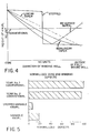
- Figure 4 shows a plot of edge knurls heights as a function of wound roll diameter, indicating qualitatively how the height can be varied in various predetermined manners in accordance with the invention, to produce the desired effective height.
- Figure 5 shows a bar chart indicating reduction in defects due to winding when the apparatus of Figure 1 is controlled by the pneumatic circuit of Figure 2.
- Figures 6 to 9 show schematically patterns of edge knurls having different densities of the knurl features, thereby producing different levels of compressibility.
- Figure 10 shows schematically a fixed density knurl having a tapered width, thereby producing different levels of compressibility.
- FIG. 1 A prior art apparatus for knurling one of the edges of a web is illustrated in Figure 1 in a sectional plan view. If desired, an opposite hand version could be provided to knurl the other edge of the web.
- a fixed base 10 supports an essentially horizontally extending bracket 12 and a knurl housing 14. Within housing 14, a shaft 16 is mounted for rotation within a pair of bearings 18.
- a knurling wheel 20 is fixed to shaft 16 and is provided in the known manner on its cylindrical outer surface with a pattern of peaks and indentations which will produce a knurl on the web.
- bracket 12 supports a cylinder body and knurl housing 22 by means of suitable guides such as ball bushings, not illustrated, which permit housing 22 to move toward and away from the axis of rotation of shaft 16.
- a shaft 24 is fixedly mounted to bracket 12 and centrally supports a pair of bearings 26 on which a knurling wheel 28 is mounted for rotation about shaft 24.
- Knurling wheel 28 typically will include a pattern of peaks and indentations to produce a knurl pattern in cooperation with knurling wheel 20; however, wheel 28 may also have a smooth exterior surface so that knurling will be produced on only one side of the web.
- Cylinder body and knurl housing 22 includes a pneumatic cylinder 30 within which is mounted a piston 32 having a rod 34 which is fixed to bracket 12. Suitable pneumatic connections, not illustrated, are provided to admit air to the head end of piston 32 to actuate the apparatus and to the rod end of piston 32 to release the apparatus.
- an edge 36 of a web product to be knurled is pulled between knurling wheels 20, 28.
- Pressurized air is admitted to the head end of piston 32, thereby causing cylinder body and knurl housing 22 to move toward knurl housing 14 until knurling wheels 20, 28 engage the opposite sides of the web product.
- Sufficient air pressure is applied to emboss edge 36 with the desired knurling height as the web product is pulled between the knurling wheels.
- pressurized air is admitted to the rod end of piston 32 and released from the head end, thereby causing cylinder body and knurl housing 22 to move away from knurl housing 14 until knurling wheels 20, 28 no longer engage edge 36.
- the prior art practice with such an apparatus has been to maintain an essentially constant pressure at the head end of piston 32 during knurling, so that a knurling pattern of substantially constant thickness and properties is produced along the web, leading to the additional quality problems previously discussed when larger rolls are wound.
- the compressibility of the edge knurls is varied from a minimum near the end of the web which is attached to a core during winding to a maximum near the end of the web which is at the outer surface of the completed roll.
- such a change in compressibility is provided by varying the radial thickness of the edge knurl as the diameter of the winding roll increases. The thickness of the edge knurl is reduced slowly or tapered as the roll is wound.
- a web having a nominal thickness of 0.005 inch (0.0127 cm) near the core of the roll might be wound with a knurl thickness of 0.008 inch (0.0203 cm) near the core, which would be reduced linearly or non-linearly to a final knurl thickness of 0.0055 inch (0.0139 cm) at the outside of the completed roll.
- Figure 2 illustrates a pneumatic control circuit for an apparatus of the type shown in Figure 1 which enables the apparatus to operate in accordance with the invention.
- Figure 3 illustrates schematically a web winding apparatus comprising the knurler of Figure 1 and the control circuit of Figure 2.
- a pneumatic pressure controller 38 is provided which produces a baseline pressure that can be used to produce edge knurls of constant compressibility.
- this pressure passes a normally open valve 40 and is introduced to port B of a conventional pneumatic computing relay 42, such as a Model 22 computing relay made by the Fairchild Company located in Winston-Salem, North Carolina.
- an electrical signal proportional to the tension being applied to the web during winding is applied to a conventional current to pneumatic transducer 44, such as a Type 1000 I/P Transducer made by Bellofram Corp. located in Burlington, Massachusetts.
- a conventional current to pneumatic transducer 44 such as a Type 1000 I/P Transducer made by Bellofram Corp. located in Burlington, Massachusetts.
- the pressure from transducer 44 passes to a conventional pneumatic ratio relay 46, such as a Model 29 Ratio Relay also made by the Fairchild Company, which can be used to amplify or reduce the pressure from transducer 44, depending on the operating ranges of transducer 44, computing relay 42 and cylinder 30 necessary to produce the particular knurling height desired.
- the output pressure from relay 46 is introduced to port A of relay 42.
- the pressures from relay 42 and controller 38 are added by relay 42 and the sum pressure may be biassed, in a manner typical for such relays, by changing the position of adjustment screw 48 of relay 42.
- the resultant pressure is then passed through a normally open valve 50 and admitted to the head end of piston 32 to cause the knurling wheels 20, 28 to engage edge 36. Because the signal to transducer 44 decreases as the winding tension drops, the pressure applied to knurling wheels 20, 28 will decrease in proportion, causing the height of the knurls to decrease along the length of the web.
- Valve 52 is closed during operation to produce knurls of varying height; however, it would be opened and valves 40, 50 would be closed to produce knurls of constant height.
- the unknurled web passes over an idler roll 54; and, following knurling, the knurled web passes around an idler roll 56, over a driven roll 58 and beneath a pressure roll 60, around two or more idler rolls 62, 64 and on to the roll 66 being wound.
- roll 66 is rotated by a motor 68 whose drive current is a function of the tension applied to the web during winding, as will be understood by those skilled in the art.
- Figure 4 illustrates how the effective height would decrease almost linearly using the control of Figure 2 in cases where the winding tension decreases linearly.
- a conventional programmable pressure controller such as a Distributed Process Control System, MOD 300 made by Asea- Brown Boveri located in Columbus, Ohio, not illustrated, could be used to vary the pressure acting on piston 32 to vary the effective height of the edge knurls in a wide variety of predetermined manners.
- Such a system could reference the length of web in the wound roll, rather than the winding tension.
- a controller could produce a stepped change in knurl height from an initial relatively high level to a final substantially lower level.
- a programmable controller could be used to vary the pressure on piston 32 to cause a non-linear taper.
- the programmable controller could be used to provide a reverse taper at the end which initially is at the outside of the roll to aid in the rewinding of the web.
- Figure 5 shows the dramatic decrease in normalized defects which has been achieved when webs are knurled in accordance with the invention.
- knurl heights are as measured prior to winding.
- the bars for the two conventional years are based on an 8000 foot (2438 m) web having a width of 50 to 60 inches (127 to 152 cm), a thickness of 0.005 to 0.006 inch (0.010 to 0.015 cm) and a constant height knurling pattern of about 0.0078 inch (0.0198 cm).
- normalized defects is meant that the conventional defect level was highest in year #1; and the defect levels for the other cases were normalized by dividing their defect rate by the rate for year # 1.
- the apparatus of Figures 1 and 2 is effective to change the compressibility of the knurling by changing the height of the knurling pattern above the web along the length of the web.
- compressibility can also be varied by changing the density of the knurling pattern longitudinally or transversely of the web, or both; by changing the transverse width of the knurling pattern; or by a combination of these effects.
- laser knurling techniques of the general type disclosed in U.S. Patent 4,942,000 can be used in accordance with the present invention to change the height and/or density of the knurling pattern either longitudinally or transversely, or both, with corresponding changes in compressibility of the knurling pattern.
- Figures 6 and 8 show plan and edge views of an edge knurl having a regular spiral pattern of knurl features, such as can be readily produced using laser knurling techniques.
- Figures 7 and 9 show plan and edge views of a less dense, or more sparse, pattern of such knurl features. By changing the density of such patterns, the compressibility of the pattern can be changed proportionately.
- Figure 10 illustrates, how the transverse width of a fixed density knurling pattern can be tapered from one end of the web to the other.
Abstract
Description
- The invention concerns apparatus and methods for knurling the edges of a web prior to winding and web products provided with such knurling. More particularly, the invention relates to such apparatus, methods and web products in which the effective height of the knurling varies in a predetermined manner along the length of the web in order to minimize the occurrence of certain irregularities during winding. As used in this specification, "knurling" refers to processes for producing a regular or irregular, constant or varying pattern of protuberances, bumps, raised lines or similar raised features on one or both sides of a web; and "knurl" refers to such patterns. As used in this specification, "compressibility" refers to the ease with which such patterns can be compressed; so that, "high compressibility" knurls are more easily compressed than "low compressibility" knurls. As used in this specification, "effective height" refers to the increased radial spacing of roll convolutions in the knurled areas, as compared to the radial spacing in unknurled areas.
- During the manufacture of various types of web materials such as photographic film base, longitudinally extending knurl patterns frequently are provided along the length of the web at one or both edges. Such knurl patterns are areas of the web near its edges where the web has been functionally thickened by a mechanical embossing process, for example, such as that shown in commonly assigned U.S. Patent 3,502,765. The use of knurl patterns at the edges of the web, hereinafter referred to as "edge knurls", reduces or eliminates several commonly recognized quality problems related to winding of such webs, including hard streaks caused by transverse variations in the thickness of the web which persist over a considerable length; pressure damage to coatings on the web due to contact between convolutions of the wound web; surface skidding of convolutions over one another due to air entrainment into the roll during winding; and core impressions due to the edge of the end of the web and any tape used to attach the web to the winding core.
- The edge knurls provide an increased radial spacing between the convolutions of the roll which helps to reduce the severity of such recognized problems. However, when a web of photographic film base, for example a web having a width in the range of 40 to 60 inches (102 to 152 cm) and a thickness in the range of 0.004 to 0.006 inch (0.010 to 0.015 cm), is wound into a roll of greater than about 18 inches (45.72 cm) diameter, certain additional quality problems may be introduced, including excessive distortion of the web in and near the edge knurls; buckling collapse of the wound roll in the area between the edge knurls; and shifting or telescoping of the wound roll. One of the reasons for these additional quality problems is that the edge knurls on each convolution build up on the edge knurls of the preceding convolutions as winding proceeds. At rather large roll diameters, when many convolutions have been wound, the build up is high and contributes to the additional problems; so that, effectively thinner edge knurls would be desirable. On the other hand, if the thickness of the edge knurls is fixed at a lower value to minimize build up near the outside of larger diameter rolls and thus reduce the additional problems, the recognized quality problems described in the preceding paragraph become worse, particularly near the core of the wound roll. Thus, a need has existed for an improvement in such edge knurls which would help to alleviate both the recognized and the additional quality problems.
- The apparatus and methods of the invention are useful for variably knurling the edges of a web of sheet material such as photographic film base. A web having longitudinal edges is conveyed along a path. Along the longitudinal edges on one or both sides of the web is applied at least one longitudinally extending pattern of edge knurls having a height extended past the surface of the remainder of the web, the height or compressibility of the edge knurls varying along the length of the web in a predetermined manner. Preferably, the height of the edge knurls is greatest at the end of the web near the core of the roll and least near the outside convolution of the roll. Finally, the web is wound into a roll after application of the edge knurls. Variation in effective height is achieved either by varying the as-knurled height of the edge knurls; or by varying the density of the patterns of edge knurls to vary the degree of compression of the edge knurls when the roll is wound, thus varying the effective height. The pattern of edge knurls may be continuous or intermittent and the effective height may vary linearly or non-linearly or may be stepped. The edge knurls may be applied by hot or cold mechanical embossing, by laser knurling, by ultrasonic knurling, by corona discharge knurling and by any other suitable technique which will produce the desired change in effective height in accordance with a predetermined pattern. The effective height of the edge knurls may be proportional to the tension applied to the web during winding, which typically decreases as winding proceeds, or may be varied in a range of patterns as necessary to alleviate the quality problems otherwise introduced during winding. The article of manufacture of the invention comprises a web of material having edge knurls whose effective height varies along the length of the web in the manner just described.
- The apparatus and method of the invention are effective to change the compressibility of edge knurling by changing the height of the knurling pattern longitudinally of the web; or by changing the density of the knurling pattern longitudinally or transversely of the web, or both.
- The foregoing and other objectives, features and advantages of the invention will be apparent from the following more particular description of the preferred embodiments of the invention, as illustrated in the accompanying drawings.
- Figure 1 shows a section view through a prior art knurling apparatus of a type useful in accordance with the invention.
- Figure 2 shows a schematic pneumatic control circuit useful with the apparatus of Figure 1.
- Figure 3 shows schematically a web knurling and winding system embodying the apparatus of Figures 1 and 2.
- Figure 4 shows a plot of edge knurls heights as a function of wound roll diameter, indicating qualitatively how the height can be varied in various predetermined manners in accordance with the invention, to produce the desired effective height.
- Figure 5 shows a bar chart indicating reduction in defects due to winding when the apparatus of Figure 1 is controlled by the pneumatic circuit of Figure 2.
- Figures 6 to 9 show schematically patterns of edge knurls having different densities of the knurl features, thereby producing different levels of compressibility.
- Figure 10 shows schematically a fixed density knurl having a tapered width, thereby producing different levels of compressibility.
- The following is a detailed description of the preferred embodiments of the invention, reference being made to the drawings in which the same reference numerals identify the same elements of structure in each of the several Figures.
- A prior art apparatus for knurling one of the edges of a web is illustrated in Figure 1 in a sectional plan view. If desired, an opposite hand version could be provided to knurl the other edge of the web. A
fixed base 10 supports an essentially horizontally extendingbracket 12 and aknurl housing 14. Withinhousing 14, ashaft 16 is mounted for rotation within a pair ofbearings 18. Aknurling wheel 20 is fixed toshaft 16 and is provided in the known manner on its cylindrical outer surface with a pattern of peaks and indentations which will produce a knurl on the web. - Opposite
knurling wheel 20,bracket 12 supports a cylinder body andknurl housing 22 by means of suitable guides such as ball bushings, not illustrated, which permithousing 22 to move toward and away from the axis of rotation ofshaft 16. Ashaft 24 is fixedly mounted tobracket 12 and centrally supports a pair ofbearings 26 on which aknurling wheel 28 is mounted for rotation aboutshaft 24.Knurling wheel 28 typically will include a pattern of peaks and indentations to produce a knurl pattern in cooperation withknurling wheel 20; however,wheel 28 may also have a smooth exterior surface so that knurling will be produced on only one side of the web. Cylinder body andknurl housing 22 includes apneumatic cylinder 30 within which is mounted apiston 32 having arod 34 which is fixed tobracket 12. Suitable pneumatic connections, not illustrated, are provided to admit air to the head end ofpiston 32 to actuate the apparatus and to the rod end ofpiston 32 to release the apparatus. - In operation of the apparatus of Figure 1, an
edge 36 of a web product to be knurled is pulled betweenknurling wheels piston 32, thereby causing cylinder body andknurl housing 22 to move towardknurl housing 14 until knurlingwheels emboss edge 36 with the desired knurling height as the web product is pulled between the knurling wheels. To stop knurling, pressurized air is admitted to the rod end ofpiston 32 and released from the head end, thereby causing cylinder body andknurl housing 22 to move away fromknurl housing 14 untilknurling wheels edge 36. The prior art practice with such an apparatus has been to maintain an essentially constant pressure at the head end ofpiston 32 during knurling, so that a knurling pattern of substantially constant thickness and properties is produced along the web, leading to the additional quality problems previously discussed when larger rolls are wound. - In accordance with a preferred embodiment of the invention, the compressibility of the edge knurls is varied from a minimum near the end of the web which is attached to a core during winding to a maximum near the end of the web which is at the outer surface of the completed roll. In a specific embodiment, such a change in compressibility is provided by varying the radial thickness of the edge knurl as the diameter of the winding roll increases. The thickness of the edge knurl is reduced slowly or tapered as the roll is wound. For example, in a web of triacetate film base such as used in various photographic products, a web having a nominal thickness of 0.005 inch (0.0127 cm) near the core of the roll might be wound with a knurl thickness of 0.008 inch (0.0203 cm) near the core, which would be reduced linearly or non-linearly to a final knurl thickness of 0.0055 inch (0.0139 cm) at the outside of the completed roll. In such a roll, this would provide a significant enough buildup of the edge knurls near the core to minimize the recognized quality problems, but would also prevent an excessive buildup of the edge knurls near the outside of the winding roll, thus minimizing the additional quality problems, essentially without regard to the width and length of the web or to the tension applied during winding.
- Figure 2 illustrates a pneumatic control circuit for an apparatus of the type shown in Figure 1 which enables the apparatus to operate in accordance with the invention. Figure 3 illustrates schematically a web winding apparatus comprising the knurler of Figure 1 and the control circuit of Figure 2. As in a conventional knurling apparatus, a
pneumatic pressure controller 38 is provided which produces a baseline pressure that can be used to produce edge knurls of constant compressibility. In accordance with the invention, this pressure passes a normallyopen valve 40 and is introduced to port B of a conventionalpneumatic computing relay 42, such as a Model 22 computing relay made by the Fairchild Company located in Winston-Salem, North Carolina. At the same time, an electrical signal proportional to the tension being applied to the web during winding is applied to a conventional current topneumatic transducer 44, such as a Type 1000 I/P Transducer made by Bellofram Corp. located in Burlington, Massachusetts. In this example, the winding tension applied to the web is reduced as the diameter of the wound roll grows, to minimize creation of defects due to the winding process. The pressure fromtransducer 44 passes to a conventionalpneumatic ratio relay 46, such as a Model 29 Ratio Relay also made by the Fairchild Company, which can be used to amplify or reduce the pressure fromtransducer 44, depending on the operating ranges oftransducer 44, computingrelay 42 andcylinder 30 necessary to produce the particular knurling height desired. The output pressure fromrelay 46 is introduced to port A ofrelay 42. The pressures fromrelay 42 andcontroller 38 are added byrelay 42 and the sum pressure may be biassed, in a manner typical for such relays, by changing the position ofadjustment screw 48 ofrelay 42. The resultant pressure is then passed through a normallyopen valve 50 and admitted to the head end ofpiston 32 to cause theknurling wheels edge 36. Because the signal to transducer 44 decreases as the winding tension drops, the pressure applied to knurlingwheels Valve 52 is closed during operation to produce knurls of varying height; however, it would be opened andvalves - As shown in Figure 3, to reach the knurler of Figure 1, the unknurled web passes over an
idler roll 54; and, following knurling, the knurled web passes around anidler roll 56, over a drivenroll 58 and beneath apressure roll 60, around two or more idler rolls 62, 64 and on to theroll 66 being wound. As indicated schematically, roll 66 is rotated by amotor 68 whose drive current is a function of the tension applied to the web during winding, as will be understood by those skilled in the art. - Though the embodiment of the invention shown in Figures 1 and 2 provides for controlling knurling pressure as a function of tension applied during winding, it is also within the scope of the invention to control the knurling pressure without reference to the winding tension, to produce different patterns of compressibility along the roll. For example, Figure 4 illustrates how the effective height would decrease almost linearly using the control of Figure 2 in cases where the winding tension decreases linearly. Alternatively, a conventional programmable pressure controller, such as a Distributed Process Control System, MOD 300 made by Asea- Brown Boveri located in Columbus, Ohio, not illustrated, could be used to vary the pressure acting on
piston 32 to vary the effective height of the edge knurls in a wide variety of predetermined manners. Such a system could reference the length of web in the wound roll, rather than the winding tension. For example, such a controller could produce a stepped change in knurl height from an initial relatively high level to a final substantially lower level. Similarly, such a programmable controller could be used to vary the pressure onpiston 32 to cause a non-linear taper. In situations where a roll is to be unwound for treatment such as application of a coating and then rewound from the other end, the programmable controller could be used to provide a reverse taper at the end which initially is at the outside of the roll to aid in the rewinding of the web. - Figure 5 shows the dramatic decrease in normalized defects which has been achieved when webs are knurled in accordance with the invention. In the following data, knurl heights are as measured prior to winding. The bars for the two conventional years are based on an 8000 foot (2438 m) web having a width of 50 to 60 inches (127 to 152 cm), a thickness of 0.005 to 0.006 inch (0.010 to 0.015 cm) and a constant height knurling pattern of about 0.0078 inch (0.0198 cm). By "normalized defects" is meant that the conventional defect level was highest in year #1; and the defect levels for the other cases were normalized by dividing their defect rate by the rate for year # 1. When several hundred rolls of the same types of webs were provided with a variable knurl which started at height of 0.0085 to 0.0095 inch (0.0215 to 0.0240 cm) and tapered to a height of 0.0068 to 0.0073 inch (0.017 to 0.0185 cm), normalized defects were reduced by a factor of about five. When fifty to sixty rolls of the same types of webs were provided with a stepped variable knurl of the same thickness range, normalized defects were reduced by a factor of about ten.
- Although the knurling produced by the apparatus of Figures 1 and 2 is cold embossed, those skilled in the art will realize that other knurling techniques also could be used in accordance with the invention, such as hot knurling, ultrasonic knurling, laser knurling and the like. For example, ultrasonic knurling apparatus of the type shown in U.S. Patent 4,247,273 can be used in accordance with the invention to change the height of a fixed knurl pattern.
- The apparatus of Figures 1 and 2 is effective to change the compressibility of the knurling by changing the height of the knurling pattern above the web along the length of the web. However, compressibility can also be varied by changing the density of the knurling pattern longitudinally or transversely of the web, or both; by changing the transverse width of the knurling pattern; or by a combination of these effects. For example, laser knurling techniques of the general type disclosed in U.S. Patent 4,942,000 can be used in accordance with the present invention to change the height and/or density of the knurling pattern either longitudinally or transversely, or both, with corresponding changes in compressibility of the knurling pattern. Figures 6 and 8 show plan and edge views of an edge knurl having a regular spiral pattern of knurl features, such as can be readily produced using laser knurling techniques. In contrast, Figures 7 and 9 show plan and edge views of a less dense, or more sparse, pattern of such knurl features. By changing the density of such patterns, the compressibility of the pattern can be changed proportionately. Figure 10 illustrates, how the transverse width of a fixed density knurling pattern can be tapered from one end of the web to the other.
- While our invention has been shown and described with reference to particular embodiments thereof, those skilled in the art will understand that other variations in form and detail may be made without departing from the scope and spirit of our invention.
Claims (11)
- Apparatus for providing an edge knurl on a web of sheet material, comprising:
means (54-60) for conveying a web having longitudinal edges (36) along a path;
means (10-34) for applying to said longitudinal edges on at least one side of said web at least one longitudinally extending pattern of regions having a height extended past the surface of the remainder of said web; and
means (38-52) for controlling said means for applying to vary the compressibility of said regions in a predetermined manner along the length of said web; and
means (62-68) for winding said web into a roll following application of said pattern said web having an inner end and an outer end. - Apparatus according to Claim 1, wherein said means for applying comprises a pair of patterned drums (20,28) at each said longitudinal edge, one drum on each side of said web; and said means for controlling presses said drums into contact with said web with changing force to vary said compressibility.
- Apparatus according to Claim 2, wherein said means for winding comprises means for reducing the tension applied to the web as winding progresses and said means for controlling reduces the pressure on said drums in response to reduction in said tension.
- Apparatus according to Claim 1, wherein said means for applying comprises a laser knurler.
- Apparatus according to Claim 1, wherein said means for applying comprises an ultrasonic knurler.
- An article of manufacture comprising:
a roll (66) of web material having longitudinal edges (36); and
along said longitudinal edges on at least one side, said web material having an inner end and an outer end in said roll of said web, at least one longitudinally extending pattern of regions having a height extended past the surface of the remainder of said web, the compressibility of said regions varying along the length of said web in a predetermined manner. - A method for knurling the edges of a web of sheet material, comprising the steps of:
conveying a web having longitudinal edges (36) along a path;
applying to said longitudinal edges on at least one side of said web at least one longitudinally extending pattern of regions having a height extended past the surface of the remainder of said web, the compressibility of said regions varying along the length of said web in a predetermined manner; and
winding said web into a roll (66), said web having an inner end and an outer end in said roll. - A method according to Claim 7, further comprising the steps of:
providing a pair of patterned drums (20,28) at each said longitudinal edge, one drum on each side of said web; and
pressing said drums into contact with said web with changing force to vary said height. - A method according to Claim 7, further comprising the steps of:
reducing the tension applied to said web as winding progresses; and
reducing the pressure on said drums in response to reduction in said tension. - A method according to Claim 7, wherein said applying step is accomplished using a laser.
- A method according to Claim 7, wherein said applying step is accomplished using ultrasonic energy.
Applications Claiming Priority (2)
| Application Number | Priority Date | Filing Date | Title |
|---|---|---|---|
| US07/904,103 US5393589A (en) | 1992-06-24 | 1992-06-24 | Apparatus and method for variably knurling edges of web and product produced thereby |
| US904103 | 1992-06-24 |
Publications (2)
| Publication Number | Publication Date |
|---|---|
| EP0580523A1 true EP0580523A1 (en) | 1994-01-26 |
| EP0580523B1 EP0580523B1 (en) | 1996-04-17 |
Family
ID=25418560
Family Applications (1)
| Application Number | Title | Priority Date | Filing Date |
|---|---|---|---|
| EP93420252A Expired - Lifetime EP0580523B1 (en) | 1992-06-24 | 1993-06-17 | Apparatus and methods for knurling edges of web and product produced thereby |
Country Status (4)
| Country | Link |
|---|---|
| US (1) | US5393589A (en) |
| EP (1) | EP0580523B1 (en) |
| JP (1) | JPH0691753A (en) |
| DE (1) | DE69302236T2 (en) |
Cited By (4)
| Publication number | Priority date | Publication date | Assignee | Title |
|---|---|---|---|---|
| EP0730949A2 (en) * | 1995-03-09 | 1996-09-11 | Fuji Photo Film Co., Ltd. | Methods of winding, annealing and unwinding a polymer film web, an annealing apparatus and a photographic film support prepared using said method or apparatus |
| EP0718088A3 (en) * | 1994-12-19 | 1996-09-18 | Eastman Kodak Co | Single-sided, cold mechanical knurling |
| EP0796802A2 (en) * | 1996-03-22 | 1997-09-24 | Orihiro Engineering Co., Ltd. | Multiple film for bags |
| CN109230728A (en) * | 2018-09-27 | 2019-01-18 | 明尼苏达矿业制造特殊材料(上海)有限公司 | Anti-deviation device |
Families Citing this family (18)
| Publication number | Priority date | Publication date | Assignee | Title |
|---|---|---|---|---|
| JP3226190B2 (en) * | 1993-10-08 | 2001-11-05 | 富士写真フイルム株式会社 | Plastic sheet having embossed surface, and embossing method and apparatus therefor |
| US5693405A (en) * | 1995-01-13 | 1997-12-02 | Tredegar Industries, Inc. | Masking film having embossed areas and unembossed areas |
| US5885642A (en) * | 1996-03-08 | 1999-03-23 | Land O'lakes, Inc. | Process for improved separation of stacked food slices |
| JP3900250B2 (en) * | 2001-10-02 | 2007-04-04 | 富士フイルム株式会社 | Thickness measuring method for thickness measuring part and web thickness measuring method |
| US7597956B2 (en) * | 2002-03-22 | 2009-10-06 | Eastman Kodak Company | Method of manufacture of a polymeric film with anti-blocking properties |
| US6858293B2 (en) * | 2002-03-22 | 2005-02-22 | Eastman Kodak Company | Cellulose film with anti-blocking properties |
| US20050136220A1 (en) * | 2003-12-19 | 2005-06-23 | Chang Park | Methods of producing recording sheets having reduced curl |
| WO2005106985A2 (en) * | 2004-04-22 | 2005-11-10 | Cree, Inc. | Improved substrate buffer structure for group iii nitride devices |
| JP2005342929A (en) * | 2004-06-01 | 2005-12-15 | Konica Minolta Opto Inc | Resin film manufacturing method, polarizing plate manufactured using resin film and liquid crystal display device manufactured using polarizing plate |
| JP4655663B2 (en) * | 2005-02-21 | 2011-03-23 | コニカミノルタオプト株式会社 | Method for producing roll-shaped film having coating layer, roll-shaped optical film, polarizing plate, liquid crystal display device |
| JP5578759B2 (en) * | 2007-08-10 | 2014-08-27 | 日東電工株式会社 | Film and manufacturing method thereof |
| KR101629980B1 (en) * | 2008-06-30 | 2016-06-13 | 코니카 미놀타 어드밴스드 레이어즈 인코포레이티드 | Resin film and method for manufacturing the same |
| KR101618387B1 (en) * | 2008-06-30 | 2016-05-04 | 코니카 미놀타 어드밴스드 레이어즈 인코포레이티드 | Optical film manufacturing method and optical film |
| JP5672654B2 (en) * | 2009-03-25 | 2015-02-18 | 東レ株式会社 | Thermoplastic resin film roll |
| JP5684545B2 (en) | 2009-12-14 | 2015-03-11 | 富士フイルム株式会社 | Polymer film, film roll and knurling roller |
| JP5751094B2 (en) * | 2011-08-29 | 2015-07-22 | コニカミノルタ株式会社 | Manufacturing method of optical film |
| JP6455198B2 (en) * | 2015-02-09 | 2019-01-23 | 日本ゼオン株式会社 | Method for producing film with concavo-convex structure and measuring method |
| JP6885389B2 (en) * | 2016-02-26 | 2021-06-16 | 日本ゼオン株式会社 | Long film |
Citations (4)
| Publication number | Priority date | Publication date | Assignee | Title |
|---|---|---|---|---|
| GB2040792A (en) * | 1979-01-24 | 1980-09-03 | Du Pont | Thin web with resiliently deformed edges |
| US4247273A (en) * | 1978-07-27 | 1981-01-27 | Agfa-Gevaert, A.G. | Method and an apparatus for cambering the edges of webs of thermoplastic materials on one and both sides using the energy of ultrasonic vibration |
| EP0079263A1 (en) * | 1981-11-05 | 1983-05-18 | Productions Textiles Et Plastiques De La Marne S.A. | Embossing machine with pressure rolls |
| US4942000A (en) * | 1986-07-30 | 1990-07-17 | Penoyer John A | Contactless knurling process for winding of high modulus thermoplastic films |
Family Cites Families (11)
| Publication number | Priority date | Publication date | Assignee | Title |
|---|---|---|---|---|
| US2335746A (en) * | 1939-03-01 | 1943-11-30 | Gen Aniline & Film Corp | Thin sheet, film, and the like |
| US3160687A (en) * | 1962-11-19 | 1964-12-08 | Alvadore M Andrews | Method and apparatus for producing perforated sheeting and tubes |
| US3539344A (en) * | 1967-05-31 | 1970-11-10 | Eastman Kodak Co | Photographic elements having protective bead coatings |
| US3502765A (en) * | 1967-08-24 | 1970-03-24 | Eastman Kodak Co | Method of controlling edge flatness of mechanically embossed oriented polymer sheeting |
| US3635609A (en) * | 1968-07-26 | 1972-01-18 | Cavitron Corp | Apparatus for embossing of materials with high-frequency vibrations |
| US3890892A (en) * | 1970-10-30 | 1975-06-24 | Eastman Kodak Co | Ultrasonic marking |
| US3749006A (en) * | 1972-02-16 | 1973-07-31 | Eastman Kodak Co | Able material method of and apparatus for ultrasonically embossing a sheet of malle |
| US4021179A (en) * | 1973-06-01 | 1977-05-03 | Agfa-Gevaert N.V. | Apparatus for the edges of thermoplastic webs |
| US4185068A (en) * | 1973-09-05 | 1980-01-22 | Hoechst Aktiengesellschaft | Process for preparing a web of film prior to winding it into a wound roll |
| US3955740A (en) * | 1975-06-09 | 1976-05-11 | Branson Ultrasonics Corporation | Vibratory seam welding apparatus |
| JPS5474862A (en) * | 1977-11-28 | 1979-06-15 | Fuji Photo Film Co Ltd | Thickening device |
-
1992
- 1992-06-24 US US07/904,103 patent/US5393589A/en not_active Expired - Lifetime
-
1993
- 1993-06-17 DE DE69302236T patent/DE69302236T2/en not_active Expired - Fee Related
- 1993-06-17 EP EP93420252A patent/EP0580523B1/en not_active Expired - Lifetime
- 1993-06-23 JP JP5152053A patent/JPH0691753A/en active Pending
Patent Citations (4)
| Publication number | Priority date | Publication date | Assignee | Title |
|---|---|---|---|---|
| US4247273A (en) * | 1978-07-27 | 1981-01-27 | Agfa-Gevaert, A.G. | Method and an apparatus for cambering the edges of webs of thermoplastic materials on one and both sides using the energy of ultrasonic vibration |
| GB2040792A (en) * | 1979-01-24 | 1980-09-03 | Du Pont | Thin web with resiliently deformed edges |
| EP0079263A1 (en) * | 1981-11-05 | 1983-05-18 | Productions Textiles Et Plastiques De La Marne S.A. | Embossing machine with pressure rolls |
| US4942000A (en) * | 1986-07-30 | 1990-07-17 | Penoyer John A | Contactless knurling process for winding of high modulus thermoplastic films |
Cited By (9)
| Publication number | Priority date | Publication date | Assignee | Title |
|---|---|---|---|---|
| EP0718088A3 (en) * | 1994-12-19 | 1996-09-18 | Eastman Kodak Co | Single-sided, cold mechanical knurling |
| US5670188A (en) * | 1994-12-19 | 1997-09-23 | Eastman Kodak Company | Apparatus for single-sided, cold mechanical knurling |
| EP0730949A2 (en) * | 1995-03-09 | 1996-09-11 | Fuji Photo Film Co., Ltd. | Methods of winding, annealing and unwinding a polymer film web, an annealing apparatus and a photographic film support prepared using said method or apparatus |
| EP0730949A3 (en) * | 1995-03-09 | 1997-01-08 | Fuji Photo Film Co Ltd | Methods of winding, annealing and unwinding a polymer film web, an annealing apparatus and a photographic film support prepared using said method or apparatus |
| US5895212A (en) * | 1995-03-09 | 1999-04-20 | Fuji Photo Film Co., Ltd. | Methods of winding, annealing and unwinding a polymer film web, an annealing apparatus and a photographic film support prepared using said method or apparatus |
| US6017212A (en) * | 1995-03-09 | 2000-01-25 | Fuji Photo Film Co., Ltd. | Methods of winding, annealing and unwinding a polymer film web, an annealing apparatus and photographic film support prepared using said method or apparatus |
| EP0796802A2 (en) * | 1996-03-22 | 1997-09-24 | Orihiro Engineering Co., Ltd. | Multiple film for bags |
| EP0796802A3 (en) * | 1996-03-22 | 2000-05-31 | Orihiro Engineering Co., Ltd. | Multiple film for bags |
| CN109230728A (en) * | 2018-09-27 | 2019-01-18 | 明尼苏达矿业制造特殊材料(上海)有限公司 | Anti-deviation device |
Also Published As
| Publication number | Publication date |
|---|---|
| DE69302236T2 (en) | 1996-11-21 |
| EP0580523B1 (en) | 1996-04-17 |
| DE69302236D1 (en) | 1996-05-23 |
| US5393589A (en) | 1995-02-28 |
| JPH0691753A (en) | 1994-04-05 |
Similar Documents
| Publication | Publication Date | Title |
|---|---|---|
| EP0580523B1 (en) | Apparatus and methods for knurling edges of web and product produced thereby | |
| US4678133A (en) | Automatic cutting and winding apparatus for a web-like material such as a film | |
| DE69923707T2 (en) | DEVICE AND METHOD FOR WRAPPING PAPER | |
| GB2255552A (en) | Winding webs | |
| DE2935743A1 (en) | ADDITIONAL DEVICE ON ROLLING DEVICES AND METHOD FOR ROLLING UP PRESSURE-SENSITIVE MATERIALS | |
| US5305963A (en) | Method and apparatus for forming rolls from strips of compressible material | |
| WO1992019522A1 (en) | Control of web winding | |
| EP0635445B1 (en) | Apparatus for winding | |
| US5848756A (en) | Method and device for the continuous winding up of a moving web | |
| US7611087B2 (en) | Method and apparatus for winding up coreless and soft-core rolls of film materials | |
| JP3652777B2 (en) | Reel winding control method for belt-shaped tire constituent member | |
| CN101665194A (en) | Winding method for polymer films and apparatus thereof | |
| US6189825B1 (en) | Method for controlling the winding density of film rolls | |
| EP0122134B1 (en) | Film winding apparatus | |
| JPH0647870Y2 (en) | Winder controller | |
| JPH06135611A (en) | Beam winding control method | |
| CN219296777U (en) | Rewinding device for production of foam sheets | |
| DE4123761A1 (en) | DEVICE FOR WINDING A RUNNING MATERIAL | |
| JPH04280755A (en) | Contact roll for sheet-shaped object winder | |
| JPH04286568A (en) | Speed control device for sheet material slitter | |
| EP0341970A2 (en) | Sheet curls reformer | |
| JPH0696420B2 (en) | Winding method | |
| JPH03223056A (en) | Method and device for taking up film or sheet | |
| JPS61273456A (en) | Winder for sheet material | |
| JPH02239065A (en) | Rewinding tension control method and rewinding device |
Legal Events
| Date | Code | Title | Description |
|---|---|---|---|
| PUAI | Public reference made under article 153(3) epc to a published international application that has entered the european phase |
Free format text: ORIGINAL CODE: 0009012 |
|
| AK | Designated contracting states |
Kind code of ref document: A1 Designated state(s): BE DE FR GB NL |
|
| 17P | Request for examination filed |
Effective date: 19940618 |
|
| 17Q | First examination report despatched |
Effective date: 19950621 |
|
| GRAH | Despatch of communication of intention to grant a patent |
Free format text: ORIGINAL CODE: EPIDOS IGRA |
|
| GRAA | (expected) grant |
Free format text: ORIGINAL CODE: 0009210 |
|
| AK | Designated contracting states |
Kind code of ref document: B1 Designated state(s): BE DE FR GB NL |
|
| REF | Corresponds to: |
Ref document number: 69302236 Country of ref document: DE Date of ref document: 19960523 |
|
| ET | Fr: translation filed | ||
| PLBE | No opposition filed within time limit |
Free format text: ORIGINAL CODE: 0009261 |
|
| STAA | Information on the status of an ep patent application or granted ep patent |
Free format text: STATUS: NO OPPOSITION FILED WITHIN TIME LIMIT |
|
| 26N | No opposition filed | ||
| REG | Reference to a national code |
Ref country code: GB Ref legal event code: IF02 |
|
| PGFP | Annual fee paid to national office [announced via postgrant information from national office to epo] |
Ref country code: NL Payment date: 20040510 Year of fee payment: 12 |
|
| PGFP | Annual fee paid to national office [announced via postgrant information from national office to epo] |
Ref country code: BE Payment date: 20040625 Year of fee payment: 12 |
|
| PGFP | Annual fee paid to national office [announced via postgrant information from national office to epo] |
Ref country code: DE Payment date: 20040630 Year of fee payment: 12 |
|
| PGFP | Annual fee paid to national office [announced via postgrant information from national office to epo] |
Ref country code: GB Payment date: 20050506 Year of fee payment: 13 |
|
| PGFP | Annual fee paid to national office [announced via postgrant information from national office to epo] |
Ref country code: FR Payment date: 20050602 Year of fee payment: 13 |
|
| PG25 | Lapsed in a contracting state [announced via postgrant information from national office to epo] |
Ref country code: BE Free format text: LAPSE BECAUSE OF NON-PAYMENT OF DUE FEES Effective date: 20050630 |
|
| PG25 | Lapsed in a contracting state [announced via postgrant information from national office to epo] |
Ref country code: NL Free format text: LAPSE BECAUSE OF NON-PAYMENT OF DUE FEES Effective date: 20060101 |
|
| PG25 | Lapsed in a contracting state [announced via postgrant information from national office to epo] |
Ref country code: DE Free format text: LAPSE BECAUSE OF NON-PAYMENT OF DUE FEES Effective date: 20060103 |
|
| NLV4 | Nl: lapsed or anulled due to non-payment of the annual fee |
Effective date: 20060101 |
|
| PG25 | Lapsed in a contracting state [announced via postgrant information from national office to epo] |
Ref country code: GB Free format text: LAPSE BECAUSE OF NON-PAYMENT OF DUE FEES Effective date: 20060617 |
|
| GBPC | Gb: european patent ceased through non-payment of renewal fee |
Effective date: 20060617 |
|
| REG | Reference to a national code |
Ref country code: FR Ref legal event code: ST Effective date: 20070228 |
|
| BERE | Be: lapsed |
Owner name: *EASTMAN KODAK CY Effective date: 20050630 |
|
| PG25 | Lapsed in a contracting state [announced via postgrant information from national office to epo] |
Ref country code: FR Free format text: LAPSE BECAUSE OF NON-PAYMENT OF DUE FEES Effective date: 20060630 |