EP0584447B1 - Current measuring appliance for a length of cable - Google Patents
Current measuring appliance for a length of cable Download PDFInfo
- Publication number
- EP0584447B1 EP0584447B1 EP93103817A EP93103817A EP0584447B1 EP 0584447 B1 EP0584447 B1 EP 0584447B1 EP 93103817 A EP93103817 A EP 93103817A EP 93103817 A EP93103817 A EP 93103817A EP 0584447 B1 EP0584447 B1 EP 0584447B1
- Authority
- EP
- European Patent Office
- Prior art keywords
- current
- measuring arrangement
- faraday
- cable
- arrangement according
- Prior art date
- Legal status (The legal status is an assumption and is not a legal conclusion. Google has not performed a legal analysis and makes no representation as to the accuracy of the status listed.)
- Expired - Lifetime
Links
Images

Classifications
-
- G—PHYSICS
- G01—MEASURING; TESTING
- G01R—MEASURING ELECTRIC VARIABLES; MEASURING MAGNETIC VARIABLES
- G01R15/00—Details of measuring arrangements of the types provided for in groups G01R17/00 - G01R29/00, G01R33/00 - G01R33/26 or G01R35/00
- G01R15/14—Adaptations providing voltage or current isolation, e.g. for high-voltage or high-current networks
- G01R15/24—Adaptations providing voltage or current isolation, e.g. for high-voltage or high-current networks using light-modulating devices
- G01R15/245—Adaptations providing voltage or current isolation, e.g. for high-voltage or high-current networks using light-modulating devices using magneto-optical modulators, e.g. based on the Faraday or Cotton-Mouton effect
- G01R15/246—Adaptations providing voltage or current isolation, e.g. for high-voltage or high-current networks using light-modulating devices using magneto-optical modulators, e.g. based on the Faraday or Cotton-Mouton effect based on the Faraday, i.e. linear magneto-optic, effect
-
- H—ELECTRICITY
- H02—GENERATION; CONVERSION OR DISTRIBUTION OF ELECTRIC POWER
- H02H—EMERGENCY PROTECTIVE CIRCUIT ARRANGEMENTS
- H02H1/00—Details of emergency protective circuit arrangements
- H02H1/0007—Details of emergency protective circuit arrangements concerning the detecting means
-
- H—ELECTRICITY
- H02—GENERATION; CONVERSION OR DISTRIBUTION OF ELECTRIC POWER
- H02H—EMERGENCY PROTECTIVE CIRCUIT ARRANGEMENTS
- H02H7/00—Emergency protective circuit arrangements specially adapted for specific types of electric machines or apparatus or for sectionalised protection of cable or line systems, and effecting automatic switching in the event of an undesired change from normal working conditions
- H02H7/26—Sectionalised protection of cable or line systems, e.g. for disconnecting a section on which a short-circuit, earth fault, or arc discharge has occured
Definitions
- the invention relates to a current measuring arrangement for a one-sided feed section of an energy core of an energy cable with at least two polarization-maintaining optical fibers, which are designed as Faraday coils and with devices at one end of the section for coupling and decoupling light and with a device for evaluating optical Signals.
- the invention is based on the object of specifying a current measuring arrangement of the type mentioned at the outset which makes it possible to ascertain more precise data about the fault current and in particular also about the fault current location of an energy path fed on one side.
- the invention realizes a combination of a concentrated and a distributed optical fiber coil in an energy line, both of which are individually controlled from the outside, where their measured values are evaluated.
- a concentrated current sensor is understood to be a tightly wound optical fiber coil and a distributed current sensor is an optical fiber coil with a long stroke, with each of which the current intensity in an electrical Conductor is measurable due to the Faraday effect.
- the optical fiber coils described in this way are referred to below as Faraday coils. Due to the Faraday effect, the magnetic field of the energy wires (or the cable shield) produces a rotation of the plane of polarization of the light radiated into the optical waveguide (generally in the infrared wavelength range).
- the optical fibers of the current sensors are led out of the power line (for example cables) receiving the conductor and provided with devices to couple the optical signals in and out.
- the decoupled signals are fed to an evaluation device (e.g. in a control room). It is known to integrate optical fibers not only in cables but also in sleeves or terminations, so that already in the Manufacture of the cables, sleeves and terminations the prerequisite for an integrated current measuring arrangement can be created.
- optical fibers are used in which the polarization state of the guided light wave is not influenced by interference.
- optical fibers are special optical fibers ("spun high birefringence" in the article by R.I. Laming and D.N. Payne in IEEC J Lightwave Techn 7: 1989: 2084) or optical fibers prepared by twisting ordinary monomode fibers (DE 2835794).
- optical waveguides that do not influence the polarization state of the optical wave will be referred to as polarization-maintaining optical waveguides.
- At least one optical waveguide is designed as a mechanically twisted single-mode optical waveguide (DE 28 35 794).
- the optical waveguides are integrated over a longer distance, preferably in the area of the cable shield, in order to implement the distributed current sensor in the cable.
- optical waveguide in the form of a helical spring around a supporting fiber and to fix it against turning back. Details of the winding of the optical waveguide are described in the dissertation by Holger Hirsch, University of Dortmund 1991. This type of optical waveguide is simple to manufacture and therefore less expensive than optical waveguides, to which the property of maintaining polarization in the drawing process must be impressed.
- the support fiber can itself be an optical waveguide, so that it can be used as an information-carrying optical waveguide in the current measuring arrangement. This has another advantage because the support fiber can be used functionally in the measuring system. During the wind around each other, both optical fibers twist around each other with the same blow (double screw).
- the information-carrying optical waveguide used as a supporting fiber can also be used as a sensor optical waveguide, for example for the purpose of transmitting operating states of the cable (temperatures or pressures) or as a return line for the signals of the current measuring arrangement. In this respect, a symmetrical design of both double-wound optical fibers is created, each with interchangeable stress on one or the other.
- the second optical fiber of the double screw can also be left in reserve and only activated if necessary. Regardless of its mode of operation (sensor for operating states or current sensor), each optical fiber of the distributed current sensor can be used as a communication optical fiber.
- the current measuring arrangement consists of 2 current sensors, one of which is a narrow and one of a wide-wound optical fiber coil.
- the concentrated Faraday coil is located on the feed side of the cable route.
- the current measuring arrangement is assigned to at least one energy wire in the energy cable.
- Each Faraday coil is an operating current sensor in its own right. If both sensor signals are compared, the measured variable is zero if there are no errors in the cable section.
- the distributed current sensor measures the fault current weighted with the distance of the fault location, based on the length of the cable route, from the beginning (infeed side) of the cable route.
- Both current sensors are installed in a cable section defining a measuring section.
- the ratio of the measurement signals thus provides the fault location z, or the relative distance z / L of the fault location from the beginning of the cable route, the relationship being simplified even if the same number of turns N1, N2 are provided in both Faraday coils.
- shield power lines There are 2 types of shield power lines.
- One form is that of the tubular form, which is characterized by a linear spread of the shield current.
- special attention must be paid to the installation of the distributed current sensor if the shield current line is screwed in the cable.
- the arrangement of the distributed sensor for this case must take into account that the magnetic field of the screen current acts in the longitudinal direction of the optical waveguide and thus the screen current can falsify the measurement.
- the distributed Faraday coil is made up of two coils with a shield current lead screwed around the energy core axis.
- An optical fiber coil is placed under the shield and counter to the shield power cable.
- a second fiber optic coil is added, which lies in the shield parallel to the shield current line and runs back to the beginning of the cable section.
- the end of this coil is provided with a mirror.
- the sum of the windings of both optical fiber coils corresponds to the number of turns N2.
- the embodiment described is independent of the order of the arrangement of the partial coils, so that the arrangement of the two partial coils can also be such that the light path first passes through an optical fiber coil in the screen and then an optical fiber coil under the screen.
- Temperature effects in mechanically twisted optical fibers create interference on the position of the polarization plane in optical fibers, which can overlay the useful effects. It is therefore provided that a mirror for reflecting the signals at the beginning of the sensor is provided at the end of each current sensor.
- This measure creates reciprocal effects in the optical fiber compensated. In particular, this measure simplifies the current measuring arrangement because the return of the optical signals to the coupling point makes a further decoupling point superfluous.
- the current measuring arrangement can be operated on one side.
- the choice of the access point to the current measuring arrangement depends on the technical circumstances. It is suggested to choose this location on the infeed side of the cable route. Regardless of the choice of the access point - a consumer (e.g. transformer) connected to the end of the cable route can be monitored together with the cable route if it is equipped with optical fibers and the optical fiber sensors of the consumer are connected to the optical fibers of the current measuring arrangement.
- a consumer e.g. transformer
- the invention can be used not only in single-core cables but also in multi-phase cables or cables with multi-core, the current measuring arrangement being integrated in the cable for each phase or energy core during the manufacturing process.
- Concentrated Faraday coils are short. For economic reasons, they are not integrated in the cable, although this is technically feasible. Concentrated Faraday coils are advantageously produced as a slide-on coil and pushed and fixed over the measuring points.
- the mirror is accommodated by means of sleeves or end closures, the design of which is familiar to the person skilled in the art.
- a cable is used in the cable section in which the distributed Faraday coil is fully integrated.
- transition elements sleeves, end closures, insulators, sets
- the transition elements By integrating the optical fibers in sleeves or end closures, or integrating one or both ends of the concentrated Faraday coil in a sleeve or an end closure, the transition from the cable route to a consumer or to another cable route can be realized very shortly. This is a particular advantage of the current measuring arrangement, namely the ability to connect the operational monitoring of further network components to the monitoring of the cable route without any space and time.
- the optical waveguide of the distributed current sensor can be designed as a sensor for operating states or as a communication optical waveguide on the cable route. Temperature sensors for energy paths are important as typical sensors.
- the optical fiber introduced as a supporting fiber can be used as a sensor for operating states. It is of particular interest for the operator of an energy route to be able to detect hot spots. The monitoring of the temperature can take place intermittently or simultaneously with the current measuring process, regardless of the operation of the current measuring arrangement. Time and / or wavelength division multiplexing methods are suitable as methods.
- temperature measurement methods based on optical backscatter effects for example Raman scattering
- a sensor system that can be operated on one side and is adapted to the current measurement results.
- the current measuring arrangement has the particular advantage that it can be used in distance or comparison protection devices.
- the measuring arrangement is used as a component within a line protection and / or monitoring system.
- Such a configuration is superior to conventional distance or comparison protection devices.
- an evaluation station which can be a component of a network control room, for example
- operating variable measurements are proposed in an energy path with the current measuring arrangement, in that signals from the current measuring sensors are also routed to an evaluation station and evaluated.
- communication data can be sent via the optical fibers. In this case, everyone must The end of the current measuring arrangement of the communication optical waveguide is led out of the cable section and connected to end-of-the-line message stations.
- the cable route is only accessed from one side.
- the entire spectrum of measurement and evaluation signals is available at this one end for further processing of an evaluation device in a control room.
- Known differential protection arrangements have the disadvantage that there must be connections to the cable at both ends of the cable route.
- the current measuring arrangement eliminates the need for external measurement signal and trigger signal transmission between both ends of the cable route.
- the protection area is 100% of the cable route. This is not achieved with conventional distance protection.
- absolute selectivity can be achieved (ie the faulty route can be specifically switched off).
- This property is particularly advantageous when existing power supply networks are expanded to include additional, single-sided cable routes (branch line).
- the possibility of fault location allows a clear assignment of the fault to the existing network or to the cable in the branch line, so that the protective devices that are already in operation are not impaired in their function.
- the current measuring arrangement is shown schematically. It consists of a concentrated Faraday current sensor and a Faraday current sensor distributed over the cable route KS , each consisting of an optical waveguide coil 42, 44 for a cable 10 .
- the first optical fiber coil 42 consists of the optical fiber 46 and is wound on the feed side 8 of the cable section KS as a concentrated coil.
- the optical waveguide coil 42 is implemented in a simple embodiment as a coil pushed onto the cable 10 .
- the second optical fiber coil 44 with the optical fiber 48 is distributed with a long stroke s over the cable route KS .
- the length of the cable route KS is L
- the location coordinate of the fault location on the cable route KS is designated z .
- the operating current flowing in the energy core 12 ( FIG. 3) of the cable is designated I.
- a fault current (earth fault) is called I F.
- the current-measuring arrangement is driven 42,44 via the light waveguide 40,48 of the control or evaluation stations 60,62 which are listed in a control room 65 are.
- the control room 65 the measured values and physical data on the operating states of the cable route are determined and evaluated and / or communication tasks are carried out.
- the current measuring arrangement has a very simple topological structure because of the access to the cable route that is only available at one point.
- Both fiber optic coils 42,44 have at the end of a mirror 43.45 for reflecting the light to the start of the optical fiber coil 42,44.
- the transition between the cable 10 and the cable in the cable section KS is made with a cable sleeve 70 .
- the optical waveguide 48 is guided through the cable sleeve 70 (reference symbol 84 ).
- a second sleeve 72 connects the cable from the cable route KS at point 90 to a further cable or to an end user.
- the end of the optical waveguide coil 44 and the mirror 45 can be integrated in the sleeve 72 .
- the installation sleeve 170 is a complete structural unit, in which the parts of the current measuring arrangement mentioned are integrated.
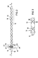
- the Fig . 2 schematically shows the representation for the arrangement of the distributed Faraday coil 44 , the shield wire line 80 of which is screwed.
- the Fig . 3 shows this in detail. As already shown in Fig . 1, there is a mirror 45 at the end of the distributed Faraday coil 44 .
- the Faraday coil 44 lying in the cable section with a long lay is formed from two optical waveguide lines 50, 52 .
- An optical fiber 52 is laid as a coil under the cable shield 80 in counter-strike to it.
- the other optical waveguide 50 runs back as a second coil to the beginning of the cable section in the cable shield 80 parallel to the shield wires 82 (shown in broken lines).
- the sum of the turns of both optical waveguide coils 50 , 52 form the relevant number of turns N2 of the concentrated current sensor 44 .
- the magnetic field of the energy core 12 and the magnetic field of the screen current act on the optical waveguide 52 located under the screen 80 .
- the effect of the magnetic field of the shield current line 80 is compensated for by this arrangement.
- the order of the arrangement of both optical fibers 50, 52 is arbitrary. For the compensation effect, it is irrelevant whether the light is first in the optical fiber 52 runs under the screen to the end of the cable route KS and then in the optical fiber 50 in the screen position to the mirror 45 or whether it first runs in the optical fiber 50 in the screen position to the end of the cable route KS and then under the screen to the mirror 45 .
- An installation sleeve 170 can be provided on the feed side 8 of the cable route.
- the concentrated Faraday coil 42 it includes the feedthroughs of the optical waveguides to the outside and also the mirrors 43, 45 .
Abstract
Description
Die Erfindung betrifft eine Strommeßanordnung für eine einseitig gespeiste Strecke einer Energieader eines Energiekabels mit mindestens zwei polarisationserhaltenden Lichtwellenleitern, die als Faraday-Spulen ausgebildet sind und mit an einem Ende der Strecke vorhandenen Einrichtungen zum Ein- und Auskoppeln von Licht und mit einer Einrichtung zur Auswertung optischer Signale.The invention relates to a current measuring arrangement for a one-sided feed section of an energy core of an energy cable with at least two polarization-maintaining optical fibers, which are designed as Faraday coils and with devices at one end of the section for coupling and decoupling light and with a device for evaluating optical Signals.
Es wurde schon vorgeschlagen, zwei in gleich langen Kabelstrecken integrierte Lichtwellenleiter jeweils mit unterschiedlichem Schlag in Reihe hintereinander zu schalten und diese Anordnung als Einrichtung zur Detektion eines Fehlerstroms über die Änderung des Drehwinkels der Polarisationsebene (Faraday-Effekt) zu verwenden (EP 0 108 012). In einer Strommeßanordnung der eingangs genannten Art wurde vorgeschlagen, in derselben Kabelstrecke zwei langgestreckte Lichtwellenleiterspulen entgegengesetzer Schlagrichtung hintereinander zu schalten (DE 36 15 557). Mit solchen Anordnungen ist es jedoch nicht möglich, die Fehlerstromstärke oder sogar die örtliche Lage des Fehlers in einer einseitig gespeisten Kabelstrecke festzustellen. Solche Anordnungen haben nur die Eigenschaft eines Fehlermelders, solange der Fehler nicht am Anfang oder am Ende der Strecke auftritt.It has already been proposed to connect two optical waveguides integrated in the same length of cable in series, each with a different stroke, and to use this arrangement as a device for detecting a fault current by changing the angle of rotation of the polarization plane (Faraday effect) (EP 0 108 012) . In a current measuring arrangement of the type mentioned at the beginning, it was proposed to connect two elongated optical waveguide coils in the opposite direction of lay in the same cable section (DE 36 15 557). With such arrangements, however, it is not possible to unilaterally locate the fault current or even the location of the fault determined fed cable route. Such arrangements only have the property of an error detector, as long as the error does not occur at the beginning or at the end of the route.
Der Erfindung liegt die Aufgabe zugrunde, eine Strommeßanordnung der eingangs genannten Art anzugeben, welche es gestattet, genauere Daten über den Fehlerstrom und insbesondere auch über den Fehlerstromort einer einseitig gespeisten Energiestrecke zu ermitteln.The invention is based on the object of specifying a current measuring arrangement of the type mentioned at the outset which makes it possible to ascertain more precise data about the fault current and in particular also about the fault current location of an energy path fed on one side.
Die Aufgabe wird erfindungsgemäß mit den Merkmalen des Hauptanspruchs gelöst. Vorteilhafte Weiterbildungen finden sich in den Unteransprüchen.The object is achieved with the features of the main claim. Advantageous further developments can be found in the subclaims.
Technische Vorteile der Strommeßanordnung: Sie ist ein Dreifachsystem. Mit ihr ist die Messung (und Überwachung) des Betriebsstroms möglich und sie ist sowohl als Differential-, als auch als Distanzschutz einsetzbar.Technical advantages of the current measuring arrangement: It is a triple system. With it, the measurement (and monitoring) of the operating current is possible and it can be used both as differential and distance protection.
Mit der Erfindung wird eine Kombination einer konzentrierten und einer verteilten Lichtwellenleiterspule in einer Energieleitung realisiert, die beide einzeln von außen angesteuert werden, wo ihre Meßwerte ausgewertet werden. Als konzentrierter Stromsensor wird eine enggewickelte Lichtwellenleiter-Spule und als verteilter Stromsensor eine Lichtwellenleiter-Spule mit langem Schlag verstanden, mit denen jeweils die Stromstärke in einem elektrischen Leiter aufgrund des Faraday-Effekts meßbar ist. Die so beschriebenen Lichtwellenleiterspulen werden im folgenden als Faraday-Spulen bezeichnet. Das Magnetfeld der Energieader (oder des Kabelschirms) erzeugt aufgrund des Faraday-Effekts eine Drehung der Polarisationsebene des in den Lichtwellenleiter eingestrahlten Lichts (in der Regel im infraroten Wellenlängenbereich). In konzentrierten Stromsensoren wird die Messung des Faraday-Effekts auf eine im Vergleich zur Länge der Energieleitung (km) vernachlässigbar kurzen Strecke (cm) begrenzt. Verteilte Stromsensoren erfassen die Faraday- Drehung demgegenüber auf einer ausgedehnten Strecke, bis hin zur gesamten Leitungslänge.The invention realizes a combination of a concentrated and a distributed optical fiber coil in an energy line, both of which are individually controlled from the outside, where their measured values are evaluated. A concentrated current sensor is understood to be a tightly wound optical fiber coil and a distributed current sensor is an optical fiber coil with a long stroke, with each of which the current intensity in an electrical Conductor is measurable due to the Faraday effect. The optical fiber coils described in this way are referred to below as Faraday coils. Due to the Faraday effect, the magnetic field of the energy wires (or the cable shield) produces a rotation of the plane of polarization of the light radiated into the optical waveguide (generally in the infrared wavelength range). In concentrated current sensors, the measurement of the Faraday effect is limited to a short distance (cm) that is negligible compared to the length of the power line (km). In contrast, distributed current sensors record the Faraday rotation over an extended distance, up to the entire cable length.
Es ist bekannt, daß sich torsionsbedingte reziproke Störeffekte, z.B. der Temperatureinfluß, bei der Umkehrung des optischen Weges auslöschen, während der nichtreziproke Faraday-Effekt in seiner Wirkung verdoppelt wird. Die Verdopplung des Lichtweges wird erreicht, indem das Licht am Ende der Faraday-Spule mit einem Spiegel reflektiert wird (DE 2924804).It is known that torsional reciprocal interference effects, e.g. the temperature influence, when reversing the optical path cancel, while the non-reciprocal Faraday effect is doubled in its effect. The doubling of the light path is achieved by reflecting the light at the end of the Faraday coil with a mirror (DE 2924804).
Die Lichtwellenleiter der Stromsensoren werden an einem Ende aus der den Leiter aufnehmenden Energieleitung (z.B. Kabel) herausgeführt und mit Einrichtungen versehen, um die optischen Signale ein- und auszukoppeln. Die ausgekoppelten Signale werden einer Auswerteeinrichtung (z. B. in einer Leitwarte) zugeführt. Es ist bekannt, Lichtwellenleiter nicht nur in Kabeln sondern auch in Muffen oder Endverschlüssen zu integrieren, so daß schon bei der Herstellung der Kabel, Muffen und Endverschlüsse die Voraussetzung für eine integrierte Strommeßanordnung geschaffen werden kann.At one end, the optical fibers of the current sensors are led out of the power line (for example cables) receiving the conductor and provided with devices to couple the optical signals in and out. The decoupled signals are fed to an evaluation device (e.g. in a control room). It is known to integrate optical fibers not only in cables but also in sleeves or terminations, so that already in the Manufacture of the cables, sleeves and terminations the prerequisite for an integrated current measuring arrangement can be created.
Störeinflüsse können in Lichtwellenleitern lineare Doppelbrechung erzeugen, die eine Fortleitung des Faraday-Signals unmöglich macht. Es werden daher für die Ausbildung des faseroptischen Stromsensors solche Lichtwellenleiter eingesetzt, bei denen der Polarisationszustand der geführten Lichtwelle nicht durch Störungen beeinflußt ist. Beispiele solcher Lichtwellenleiter sind Speziallichtwellenleiter ("spun high birefringence" im Aufsatz von R.I. Laming und D.N.Payne in IEEC J Lightwave Techn 7:1989: 2084) oder durch Torsion gewöhnlicher Monomode-Fasern präparierte Lichtwellenleiter (DE 2835794).Interferences can produce linear birefringence in optical fibers, which makes it impossible to transmit the Faraday signal. For the formation of the fiber optic current sensor, optical fibers are used in which the polarization state of the guided light wave is not influenced by interference. Examples of such optical fibers are special optical fibers ("spun high birefringence" in the article by R.I. Laming and D.N. Payne in IEEC J Lightwave Techn 7: 1989: 2084) or optical fibers prepared by twisting ordinary monomode fibers (DE 2835794).
Im folgenden sollen die Lichtwellenleiter, die den Polarisationszustand der optischen Welle nicht beeinflussen, als polarisationserhaltende Lichtwellenleiter bezeichnet werden.In the following, the optical waveguides that do not influence the polarization state of the optical wave will be referred to as polarization-maintaining optical waveguides.
In einer Ausführungsform der Strommeßanordnung wird vorgesehen, daß mindestens ein Lichtwellenleiter als mechanisch verdrillter Monomode-Lichtwellenleiter ausgebildet ist (DE 28 35 794). Die Lichtwellenleiter werden für die Realisierung des verteilten Stromsensors im Kabel auf einer längeren Strecke, vorzugsweise im Kabelschirmbereich, integriert.In one embodiment of the current measuring arrangement it is provided that at least one optical waveguide is designed as a mechanically twisted single-mode optical waveguide (DE 28 35 794). The optical waveguides are integrated over a longer distance, preferably in the area of the cable shield, in order to implement the distributed current sensor in the cable.
In einer besonderen Ausgestaltung wird vorgeschlagen, den Lichtwellenleiter in Form einer Schraubenfeder um eine Stützfaser zu winden und gegen Zurückdrehen zu fixieren. Einzelheiten des Winden des Lichtwellenleiters sind in der Dissertation von Holger Hirsch, Universität Dortmund 1991, beschrieben. Dieser Typ Lichtwellenleiter ist einfach herstellbar und daher kostengünstiger als Lichtwellenleiter, denen die Eigenschaft der Polarisationserhaltung im Ziehprozeß aufgeprägt werden muß.In a special embodiment it is proposed to wind the optical waveguide in the form of a helical spring around a supporting fiber and to fix it against turning back. Details of the winding of the optical waveguide are described in the dissertation by Holger Hirsch, University of Dortmund 1991. This type of optical waveguide is simple to manufacture and therefore less expensive than optical waveguides, to which the property of maintaining polarization in the drawing process must be impressed.
Die Stützfaser kann selbst ein Lichtwellenleiter sein, so daß sie als informationsführender Lichtwellenleiter der Strommeßanordnung einsetzbar ist. Dies bringt einen weiteren Vorteil mit sich, weil die Stützfaser funktional im Meßsystem nutzbar ist. Während des Umeinanderwindes verdrillen sich beide Lichtwellenleiter mit dem gleichen Schlag umeinander (Doppelschraube). Der als Stützfaser eingesetzte informationsführende Lichtwellenleiter kann auch als Sensorlichtwellenleiter, z.B. für Zwecke der Übermittlung von Betriebszuständen des Kabels (Temperaturen oder Drücke) oder als Rückführleitung der Signale der Strommeßanordnung eingesetzt werden. Insofern entsteht eine symmetrische Ausgestaltung beider doppelt-gewundenen Lichtwellenleiter mit jeweils austauschbarer Beanspruchung des einen oder des anderen. Der zweite Lichtwellenleiter bleiben der Doppelschraube kann aber auch in Reserve liegen und nur bei Bedarf aktiviert werden. Unabhängig von seiner Betriebsweise (Sensor für Betriebzustände oder Stromsensor) kann jeder Lichtwellenleiter des verteilten Stromsensors als Kommunikationslichtwellenleiter verwendet werden.The support fiber can itself be an optical waveguide, so that it can be used as an information-carrying optical waveguide in the current measuring arrangement. This has another advantage because the support fiber can be used functionally in the measuring system. During the wind around each other, both optical fibers twist around each other with the same blow (double screw). The information-carrying optical waveguide used as a supporting fiber can also be used as a sensor optical waveguide, for example for the purpose of transmitting operating states of the cable (temperatures or pressures) or as a return line for the signals of the current measuring arrangement. In this respect, a symmetrical design of both double-wound optical fibers is created, each with interchangeable stress on one or the other. The second optical fiber of the double screw can also be left in reserve and only activated if necessary. Regardless of its mode of operation (sensor for operating states or current sensor), each optical fiber of the distributed current sensor can be used as a communication optical fiber.
Die Strommeßanordnung besteht aus 2 Stromsensoren, von denen einer eine eng und einer eine weit gewickelte Lichtwellenleiterspule ist. Die konzentrierte Faraday-Spule ist befindet sich auf der Einspeiseseite der Kabelstrecke. Die Strommeßanordnung ist mindestens einer Energieader im Energiekabel zugeordnet.The current measuring arrangement consists of 2 current sensors, one of which is a narrow and one of a wide-wound optical fiber coil. The concentrated Faraday coil is located on the feed side of the cable route. The current measuring arrangement is assigned to at least one energy wire in the energy cable.
Jede Faraday-Spule ist für sich ein Betriebsstromsensor. Werden beide Sensorsignale verglichen, ist bei Fehlerfreiheit in der Kabelstrecke die Meßgröße Null.Each Faraday coil is an operating current sensor in its own right. If both sensor signals are compared, the measured variable is zero if there are no errors in the cable section.
Liegt ein Fehler an beliebiger Stelle der Kabelstrecke vor (Erdschluß, Phasenschluß) fließt der Betriebsstrom an der Fehlerstelle ab. Damit mißt der verteilte Stromsensor den Fehlerstrom gewichtet mit der auf die Länge der Kabelstrecke bezogenen Distanz des Fehlerorts vom Anfang (Einspeiseseite) der Kabelstrecke.If there is a fault at any point in the cable route (earth fault, phase fault), the operating current flows out at the fault point. The distributed current sensor thus measures the fault current weighted with the distance of the fault location, based on the length of the cable route, from the beginning (infeed side) of the cable route.
Beide Stromsensoren werden in einem eine Meßstrecke bestimmenden Kabelabschnitt installiert.Both current sensors are installed in a cable section defining a measuring section.
Wegen des Spiegels am Ende der Sensorandordnung gilt für die Faraday-Drehung φ der konzentrierten Faraday-Spule:![]()
![]()
Die Faraday-Drehung ist in der verteilten Faraday-Spule bei einem Fehler an der Stelle z (Koordinate des Fehlerstromorts) bei einer Streckenlänge L:![]()
![]()
Die Meßsignale der Faraday-Spulen werden einem elektronischen System zugeführt und dort ausgewertet. Beide Faraday-Meßwerte φ1 und φ2 werden ins Verhältnis gesetzt, wobei die Genauigkeit unabhängig ist von der Lage des Fehlerorts z, solange auswertbare Signale vorliegen. Also im Ergebnis:![]()
![]()
Das Verhältnis der Meßsignale liefert also den Fehlerort z, bzw. die relative Entfernung z/L des Fehlerorts von Beginn der Kabelstrecke, wobei sich die Beziehung noch vereinfachen würde, wenn in beiden Faraday-Spulen gleiche Windungszahlen N1,N2 vorgesehen werden.The ratio of the measurement signals thus provides the fault location z, or the relative distance z / L of the fault location from the beginning of the cable route, the relationship being simplified even if the same number of turns N1, N2 are provided in both Faraday coils.
Es gibt 2 Typen von Schirmstromleitungen. Die eine Form ist die der Rohrform, die durch geradlinige Ausbreitung des Schirmstroms gekennzeichnet ist. Besondere Aufmerksamkeit allerdings verlangt die Installation des verteilten Stromsensors, wenn die Schirmstromleitung als geschraubte Leitung im Kabel liegt. Die Anordnung des verteilten Sensors für diesen Fall muß berücksichtigen, daß das Magnetfeld des Schirmstroms in Längsrichtung des Lichtwellenleiters wirkt und damit der Schirmstrom die Messung verfälschen kann.There are 2 types of shield power lines. One form is that of the tubular form, which is characterized by a linear spread of the shield current. However, special attention must be paid to the installation of the distributed current sensor if the shield current line is screwed in the cable. The arrangement of the distributed sensor for this case must take into account that the magnetic field of the screen current acts in the longitudinal direction of the optical waveguide and thus the screen current can falsify the measurement.
Die verteilte Faraday-Spule wird bei einer um die Energieaderachse geschraubt geführten Schirmstromleitung aus zwei Spulen aufgebaut. Es wird eine Lichtwellenleiterspule unter den Schirm und im Gegenschlag zur Schirmstromleitung gelegt. An das Ende dieser Spule (also am Ende der Kabelstrecke) wird eine zweite Lichtwellenleiterspule angefügt, die im Schirm parallel zur Schirmstromleitung liegt und bis zum Anfang der Kabelstrecke zurückläuft. Das Ende dieser Spule wird mit einem Spiegel versehen. Die Summe der Wicklungen beider Lichtwellenleiterspulen entspricht der Windungszahl N2.The distributed Faraday coil is made up of two coils with a shield current lead screwed around the energy core axis. An optical fiber coil is placed under the shield and counter to the shield power cable. At the end of this coil (i.e. at the end of the cable section), a second fiber optic coil is added, which lies in the shield parallel to the shield current line and runs back to the beginning of the cable section. The end of this coil is provided with a mirror. The sum of the windings of both optical fiber coils corresponds to the number of turns N2.
Die beschriebene Ausführung ist unabhängig von der Reihenfolge der Anordnung der Teilspulen, so daß die Anordnung beider Teilspulen auch so sein kann, daß der Lichtweg zuerst eine Lichtwellenleiterspule im Schirm und dann eine Lichtwellenleiterspule unter dem Schirm durchläuft.The embodiment described is independent of the order of the arrangement of the partial coils, so that the arrangement of the two partial coils can also be such that the light path first passes through an optical fiber coil in the screen and then an optical fiber coil under the screen.
Temperatureffekte in mechanisch tordierten Lichtwellenleitern erzeugen Störeinflüsse auf die Lage der Polarisationsebene in Lichtwellenleitern, die die Nutzeffekte überlagern können. Es wird daher vorgesehen, daß am Ende jeden Stromsensors ein Spiegel zur Reflexion der Signale zum Anfang des Sensors vorhanden ist. Mit dieser Maßnahme werden reziproke Effekte im Lichtwellenleiter kompensiert. Insbesondere tritt mit dieser Maßnahme eine Vereinfachung der Strommeßanordnung ein, weil durch die Rückführung der optischen Signale an die Einkoppelstelle eine weitere Auskoppelstelle überflüssig wird. Die Strommeßanordnung wird einseitig betreibbar.Temperature effects in mechanically twisted optical fibers create interference on the position of the polarization plane in optical fibers, which can overlay the useful effects. It is therefore provided that a mirror for reflecting the signals at the beginning of the sensor is provided at the end of each current sensor. This measure creates reciprocal effects in the optical fiber compensated. In particular, this measure simplifies the current measuring arrangement because the return of the optical signals to the coupling point makes a further decoupling point superfluous. The current measuring arrangement can be operated on one side.
Die Wahl der Zugriffsstelle auf die Strommeßanordnung richtet sich nach den technischen Gegebenheiten. Es wird vorgeschlagen, diese Stelle auf der Einspeiseseite der Kabelstrecke zu wählen. Unabhängig von der Wahl der Zugrifsstelle - wird ein am Ende der Kabelstrecke angeschlossener Verbraucher (z.B. Transformator) zusammen mit der Kabelstrecke überwachbar, wenn dieser mit Lichtwellenleitern ausgestattet ist und die Lichtwellenleitersensoren des Verbrauchers mit den Lichtwellenleitern der Strommeßanordnung durchverbunden werden.The choice of the access point to the current measuring arrangement depends on the technical circumstances. It is suggested to choose this location on the infeed side of the cable route. Regardless of the choice of the access point - a consumer (e.g. transformer) connected to the end of the cable route can be monitored together with the cable route if it is equipped with optical fibers and the optical fiber sensors of the consumer are connected to the optical fibers of the current measuring arrangement.
Die Erfindung ist nicht nur in Einleiterkabeln sondern auch in Mehrphasenleitungen oder Kabeln mit Mehrfachadern einsetzbar, wobei für jede Phase oder jede Energieader die Strommeßanordnung im Kabel schon beim Herstellungsvorgang integriert wird.The invention can be used not only in single-core cables but also in multi-phase cables or cables with multi-core, the current measuring arrangement being integrated in the cable for each phase or energy core during the manufacturing process.
Konzentrierte Faraday-Spulen sind kurz. Aus wirtschaftlichen Gründen werden sie nicht im Kabel integriert, obwohl dies technisch machbar ist. Konzentrierte Faraday-Spulen werden vorteilhafterweise als aufschiebbare Spule hergestellt und über die Meßstellen geschoben und fixiert.Concentrated Faraday coils are short. For economic reasons, they are not integrated in the cable, although this is technically feasible. Concentrated Faraday coils are advantageously produced as a slide-on coil and pushed and fixed over the measuring points.
Die Unterbringung des Spiegels wird mittels Muffen oder Endverschlüssen bewerkstelligt, deren Ausgestaltung dem Fachmann geläufig ist. Im einfachsten Fall wird in der Kabelstrecke ein Kabel eingesetzt, in dem die verteilte Faraday-Spule vollständig integriert ist.The mirror is accommodated by means of sleeves or end closures, the design of which is familiar to the person skilled in the art. In the simplest case, a cable is used in the cable section in which the distributed Faraday coil is fully integrated.
Anstelle von besonders ausgestaltenen Garnituren bietet es sich an, Übergangsorgane (Muffen, Endverschlüsse, Isolatoren, Garnituren) von Energiestrecken so auszugestalten, daß sie die einspeiseseitige konzentrierte Spule und Einrichtungen der Sensoren, wie Spiegel, Ein- und Auskoppeleinrichtungen für Licht mit aufnehmen. Durch die Integration der Lichtwellenleiter in Muffen oder Endverschlüssen, oder die Integration eines oder beider Enden der konzentrierten Faraday-Spule in einer Muffe oder einem Endverschluß, kann der Übergang von der Kabelstrecke zu einem Verbraucher oder zu einer weiteren Kabelstrecke sehr kurz realisiert werden. Darin liegt ein besonderer Vorteil der Strommeßanordnung, nämlich räumlich und zeitlich lückenlos an die Überwachung der Kabelstrecke die Betriebsüberwachung weiterer Netzkomponenten anschließen zu können.Instead of specially designed sets, it is advisable to design transition elements (sleeves, end closures, insulators, sets) of energy paths in such a way that they also accommodate the concentrated coil and devices of the sensors, such as mirrors, coupling and decoupling devices for light. By integrating the optical fibers in sleeves or end closures, or integrating one or both ends of the concentrated Faraday coil in a sleeve or an end closure, the transition from the cable route to a consumer or to another cable route can be realized very shortly. This is a particular advantage of the current measuring arrangement, namely the ability to connect the operational monitoring of further network components to the monitoring of the cable route without any space and time.
Wie schon erwähnt, kann der Lichtwellenleiter des verteilten Stromsensors als Sensor für Betriebzustände oder als Kommunikationslichtwellenleiter auf der Kabelstrecke ausgebildet sein. Als typische Sensoren sind Temperatursensoren für Energiestrecken von Bedeutung. Als Sensor für Betriebszustände ist insbesondere der als Stützfaser eingebrachte Lichtwellenleiter einsetzbar. Es ist für den Betreiber einer Energiestrecke von besonderem Interesse, Heißstellen (hot spots) aufspüren zu können. Die Überwachung der Temperatur kann unabhängig vom Betrieb der Strommeßanordnung zeitlich intermittierend oder gleichzeitig mit dem Strommeßvorgang stattfinden. Als Verfahren bieten sich Zeit- und/oder Wellenlängenmultiplexverfahren an. Insbesondere ergibt sich bei auf optischen Rückstreueffekten (z.B. Raman-Streuung) beruhenden Temperaturmeßverfahren ein der Strommessung angepaßtes, einseitig betreibbares Sensorsystem.As already mentioned, the optical waveguide of the distributed current sensor can be designed as a sensor for operating states or as a communication optical waveguide on the cable route. Temperature sensors for energy paths are important as typical sensors. In particular, the optical fiber introduced as a supporting fiber can be used as a sensor for operating states. It is of particular interest for the operator of an energy route to be able to detect hot spots. The monitoring of the temperature can take place intermittently or simultaneously with the current measuring process, regardless of the operation of the current measuring arrangement. Time and / or wavelength division multiplexing methods are suitable as methods. In particular, in the case of temperature measurement methods based on optical backscatter effects (for example Raman scattering), a sensor system that can be operated on one side and is adapted to the current measurement results.
Die Strommeßanordnung hat den besonderen Vorteil, daß sie in Distanz- oder Vergleichsschutzeinrichtungen eingesetzt werden kann. Hierbei wird die Meßanordnung innerhalb eines Leitungsschutz- und/oder Überwachungssystem als Komponente verwendet. Eine solche Konfiguration ist herkömmlichen Einrichtungen zum Distanz- oder Vergleichsschutz überlegen. In einer verfahrensmäßigen Anwendung wird vorgeschlagen, die Meßwerte beider Stromsensoren in eine Auswertestation (die z. B. Komponente einer Netzleitwarte sein kann) zu führen und dort Fehlerstromstärke und relativen Fehlerstromort ermitteln zu lassen.The current measuring arrangement has the particular advantage that it can be used in distance or comparison protection devices. Here, the measuring arrangement is used as a component within a line protection and / or monitoring system. Such a configuration is superior to conventional distance or comparison protection devices. In a procedural application, it is proposed that the measured values of both current sensors be led to an evaluation station (which can be a component of a network control room, for example) and have the fault current strength and relative fault current location determined there.
In einer anderen Verfahrensweise werden Betriebsgrößenmessungen in einer Energiestrecke mit der Strommeßanordnung vorgeschlagen, indem Signale der Strommeßsensoren ebenfalls zu einer Auswertestation geführt und ausgewertet werden. Zusätzlich oder anstelle von Betriebsgrößenmessungen können Kommunikationsdaten über die Lichtwellenleiter geschickt werden. In diesem Fall muß an jedem Ende der Strommeßanordnung der Kommunikationslichtwellenleiter aus der Kabelstrecke herausgeführt und mit endseitigen Nachrichtenstationen verbunden werden.In another procedure, operating variable measurements are proposed in an energy path with the current measuring arrangement, in that signals from the current measuring sensors are also routed to an evaluation station and evaluated. In addition to or instead of operating size measurements, communication data can be sent via the optical fibers. In this case, everyone must The end of the current measuring arrangement of the communication optical waveguide is led out of the cable section and connected to end-of-the-line message stations.
Unabhängig von der Betriebsweise (entweder als Stromsensor oder als Betriebsgrößensensor) wird auf die Kabelstrecke nur von einer Seite aus zugegriffen. Das gesamte Spektrum der Meß- und Auswertesignale stehen an diesem einen Ende zur Weiterverarbeitung einer Auswerteeinrichtung in einer Leitwarte zur Verfügung. Bekannte Differentialschutzanordnungen haben den Nachteil, daß bei ihnen an beiden Enden der Kabelstrecke Verbindungen zum Kabel vorhanden sein müssen. Bei der Strommeßanordnung entfällt die Notwendigkeit externer Meßsignal- und Auslösesignalübertragung zwischen beiden Enden der Kabelstrecke.Regardless of the mode of operation (either as a current sensor or as an operating size sensor), the cable route is only accessed from one side. The entire spectrum of measurement and evaluation signals is available at this one end for further processing of an evaluation device in a control room. Known differential protection arrangements have the disadvantage that there must be connections to the cable at both ends of the cable route. The current measuring arrangement eliminates the need for external measurement signal and trigger signal transmission between both ends of the cable route.
Der Schutzbereich beträgt 100 % der Kabelstrecke. Dies wird durch herkömmlichen Distanzschutz nicht erreicht. Bei der Verwendung der Strommeßanordnung (zum Beispiel als Komponente in einem Leitungsschutz- und/oder Überwachungssystem) kann absolute Selektivität erzielt werden (d.h. die fehlerhafte Strecke kann gezielt abgeschaltet werden). Diese Eigenschaft ist insbesondere von Vorteil, wenn bestehende Energieversorgungsnetze um zusätzliche, einseitig gespeiste Kabelstrecken erweitert werden (Stichstrecke). Die Möglichkeit der Fehlerortung erlaubt eine eindeutige Zuordnung des Fehlers zum bestehenden Netz oder zum Kabel in der Stichstrecke, so daß bereits im Betrieb befindliche Schutzeinrichtungen in ihrer Funktion nicht beeinträchtigt werden.The protection area is 100% of the cable route. This is not achieved with conventional distance protection. When using the current measuring arrangement (for example as a component in a line protection and / or monitoring system), absolute selectivity can be achieved (ie the faulty route can be specifically switched off). This property is particularly advantageous when existing power supply networks are expanded to include additional, single-sided cable routes (branch line). The possibility of fault location allows a clear assignment of the fault to the existing network or to the cable in the branch line, so that the protective devices that are already in operation are not impaired in their function.
Ausführungsbeispiele der Erfindung werden in den Figuren näher beschrieben. Sie zeigen im Einzelnen:
- Fig. 1 und Fig. 2 schematisch die Strommeßanordnung und
- Fig. 3 eine Ausführungsform des verteilten Stromsensors.
- Fig. 1 and Fig. 2 schematically the current measuring arrangement and
- Fig. 3 shows an embodiment of the distributed current sensor.
In Fig. 1 ist schematisch die Strommeßanordnung dargestellt. Sie besteht aus einem konzentrierten und einem über die Kabelstrecke KS verteilten Faraday-Stromsensor aus jeweils einer Lichtwellenleiterspule 42,44 bei einem Kabel 10.In Fig. 1, the current measuring arrangement is shown schematically. It consists of a concentrated Faraday current sensor and a Faraday current sensor distributed over the cable route KS , each consisting of an
Die erste Lichtwellenleiterspule 42 besteht aus dem Lichtwellenleiter 46 und ist auf der Einspeiseseite 8 der Kabelstrecke KS als konzentrierte Spule gewickelt. Die Lichtwellenleiterspule 42 wird in einer einfachen Ausführung als auf das Kabel 10 aufgeschobene Spule realisiert. Die zweite Lichtwellenleiterspule 44 mit dem Lichtwellenleiter 48 ist mit langem Schlag s über der Kabelstrecke KS verteilt.The first
Die Länge der Kabelstrecke KS ist mit L, die Ortskoordinate der Fehlerstelle auf der Kabelstrecke KS wird mit z bezeichnet. Der in der Energieader 12 (Fig. 3) des Kabels fließende Betriebsstrom wird mit I bezeichnet. Ein Fehlerstrom (Erdschluß) trägt die Bezeichnung I F .The length of the cable route KS is L , the location coordinate of the fault location on the cable route KS is designated z . The operating current flowing in the energy core 12 ( FIG. 3) of the cable is designated I. A fault current (earth fault) is called I F.
Von außerhalb des Kabels wird die Strommeßanordnung 42,44 über die Lichtwellenleiter 40,48 von den Steuer- oder Auswertestationen 60,62 angesteuert, die in einer Leitwarte 65 zusammengefaßt sind. In der Leitwarte 65 werden die Meßwerte und physikalische Daten über Betriebszustände der Kabelstrecke ermittelt und ausgewertet und/oder Kommunikationsaufgaben abgewickelt. Die Strommeßanordnung hat wegen des nur an einer Stelle vorhandenen Zugangs auf die Kabelstrecke eine sehr einfache topologische Struktur.From the outside of the cable, the current-measuring arrangement is driven 42,44 via the
Beide Lichtwellenleiterspulen 42,44 haben am Ende einen Spiegel 43,45 zur Reflexion des Lichts zum Anfang der Lichtwellenleiterspulen 42,44.Both fiber optic coils 42,44 have at the end of a mirror 43.45 for reflecting the light to the start of the
Der Übergang zwischen dem Kabel 10 und dem Kabel in der Kabelstrecke KS wird mit einer Kabelmuffe 70 hergestellt. Durch die Kabelmuffe 70 ist der Lichtwellenleiter 48 hindurchgeführt (Bezugszeichen 84). Mit einer zweiten Muffe 72 wird das Kabel aus der Kabelstrecke KS an der Stelle 90 an ein weiterführendes Kabel oder an einen Endverbraucher verbunden. Es kann in der Muffe 72 das Ende der Lichtwellenleiterspule 44 und der Spiegel 45 integriert sein.The transition between the
Gestrichelt ist in der Fig. 1 eine Installationsmuffe 170 dargestellt, die anstelle der Muffe 70 vorgesehen werden kann. Die Installationsmuffe 170 umfaßt neben der Durchführung der Energieader 12 des Kabels 10 und der Schirmleitung 80 (Fig. 3) auch die konzentrierte Faraday-Spule 42, einschließlich Spiegel 43, und die Lichtwellenleiterverbindungen zur Leitwarte 65. Die Installationsmuffe 170 ist eine komplette Baueinheit, in die die erwähnten Teile der Strommeßanordnung integriert sind.Dashed is in the Fig . 1 shows an
Die Fig. 2 zeigt schematisch die Darstellung für die Anordnung der verteilten Faraday-Spule 44, deren Schirmdrahtleitung 80 geschraubt geführt ist. Die Fig. 3 zeigt dies im Detail. Wie schon in Fig. 1 dargestellt, befindet sich am Ende der verteilten Faraday- Spule 44 ein Spiegel 45.The Fig . 2 schematically shows the representation for the arrangement of the distributed
Wegen des Magnetfeldes des geschraubt geführten Schirmstroms wird eine darauf abgestimmte Anordnung der verteilten Faraday-Spule 44 gewählt. Die in der Kabelstrecke mit langem Schlag liegende Faraday-Spule 44 wird aus zwei Lichtwellenleiter-Leitungen 50,52 gebildet. Ein Lichtwellenleiter 52 wird als Spule unter den Kabelschirm 80 im Gegenschlag zu ihm gelegt. Der andere Lichtwellenleiter 50 läuft als zweite Spule zum Anfang der Kabelstrecke im Kabelschirm 80 parallel zu den (strichpunktiert gezeichneten) Schirmdrähten 82 zurück. Die Summe der Windungen beider Lichtwellenleiterspulen 50,52 bilden die maßgebliche Windungszahl N2 des konzentrierten Stromsensors 44. Auf den unter dem Schirm 80 liegenden Lichtwellenleiter 52 wirkt das Magnetfeld der Energieader 12 und das Magnetfeld des Schirmstroms. Die Wirkung des Magnetfeldes der Schirmstromleitung 80 wird durch diese Anordnung kompensiert. Die Reihenfolge der Anordnung beider Lichtwellenleiter 50,52 ist beliebig. D.h. für die Kompensationswirkung ist es unerheblich, ob das Licht zuerst im Lichtwellenleiter 52 unter dem Schirm zum Ende der Kabelstrecke KS und anschließend im Lichtwellenleiter 50 in der Schirmlage bis zum Spiegel 45 läuft oder ob es zuerst im Lichtwellenleiter 50 in der Schirmlage zum Ende der Kabelstrecke KS und dann unter dem Schirm zum Spiegel 45 läuft. Eine Installationsmuffe 170 kann an der Einspeiseseite 8 der Kabelstrecke vorgesehen sein. Sie umfaßt neben der konzentrierten Faraday-Spule 42, die Durchführungen der Lichtwellenleiter nach außen und auch die Spiegel 43,45.Because of the magnetic field of the screwed shielding current, a coordinated arrangement of the distributed
Claims (16)
- A current-measuring arrangement for a section (KS), fed from one end, of a power core (12) of a power cable (10), having at least two polarisation-maintaining optical waveguides (46,48) which are designed as Faraday coils (42,44), and having devices which are present at one end of the section (KS) and are intended for injecting and extracting light into and from the optical waveguides (46,48), and having a facility (65) for the evaluation of extracted optical signals, characterised in that, assigned to at least one power core (12) in the power cable (10),- the current-measuring arrangement is formed from a concentrated Faraday coil (42) lying on the infeed side (8) of the section (KS) and from a Faraday coil (44) distributed over the section (KS) as Faraday current sensors and- in that a mirror (43,45) for reflecting the signals is present at the end of each current sensor (42,44).
- A current-measuring arrangement according to Claim 1, characterised in that, in the case of a shielding line (80) run helically around the axis of the power core, the distributed current sensor (44), irrespective of the order of the arrangement, is formed from an optical-waveguide coil (52) lying under the shield (80) and with a cross lay relative to the shielding line and, from the end (90) of the section (KS), with another optical-waveguide coil (50) which lies in the shield (80) parallel to the shielding line, is led back to the infeed side (8) of the section (KS) and is fitted there with a mirror (45).
- A current-measuring arrangement according to one of the preceding claims, characterised in that the devices for injecting and extracting light of the control and evaluating stations (60,62) lie on the infeed side (8) of the section (KS).
- A current-measuring arrangement according to one of the preceding claims, characterised in that a mechanically twisted optical waveguide is employed as the optical waveguides (46,48) in at least one Faraday current sensor (42,44).
- A current-measuring arrangement according to Claim 4, characterised in that at least one optical waveguide (46,48) is wound helically around a supporting fibre.
- A current-measuring arrangement according to Claim 5, characterised in that the supporting fibre is designed as a polarisation-maintaining optical waveguide.
- A current-measuring arrangement according to one of Claims 1 to 3, characterised in that fibres of the spun high birefringence type are employed as the optical waveguides (46,48).
- A current-measuring arrangement according to one of Claims 5 or 6, characterised in that the supporting fibre and/or the optical waveguide (46,48) of at least one Faraday current sensor (42,44) is designed as a sensor for operating quantities and/or as a communication optical waveguide.
- A current-measuring arrangement according to one of the preceding claims, characterised in that at least one Faraday current sensor (42,44) for each phase or each power core (12) is integrated in the power cable (10).
- A current-measuring arrangement according to one of the preceding claims, characterised in that leadthroughs (84) of the optical waveguides (46,48) from the Faraday current sensors (42,44) to the control and evaluating station (60,62) are integrated in coupling boxes (70).
- A current-measuring arrangement according to Claim 10, characterised in that the beginning and/or the end of the distributed Faraday current sensor (44) and the associated leadthroughs (84,86) of the optical waveguide (48) are integrated in a coupling box (70,72).
- A current-measuring arrangement according to one of the preceding claims, characterised in that the concentrated Faraday current sensor (42) is integrated in an installation coupling box (170).
- A current-measuring arrangement according to one of the preceding claims, characterised in that the Faraday measured values of the Faraday current-measuring arrangement (42,44) are passed to a control centre (65) for the determination of the intensity (I F ) of the current or fault current and of the relative location (z/L) of the fault current.
- A current-measuring arrangement according to one of Claims 1 to 13, characterised in that monitoring of the operating quantities and/or data transmission is also carried out via the Faraday current-measuring arrangement (42,44) with the aid of communication stations connected between [sic] to each of the ends (8,90) of the cable section (KS).
- A current-measuring arrangement according to Claim 14, characterised in that the current measurement and the monitoring of the operating quantities and/or the data transmission is carried out in multiplex operation.
- A current-measuring arrangement according to one of the preceding claims, characterised in that the Faraday current-measuring arrangement (42,44) is used as a component in a line-protection and/or monitoring system.
Applications Claiming Priority (2)
| Application Number | Priority Date | Filing Date | Title |
|---|---|---|---|
| DE4227904A DE4227904C1 (en) | 1992-08-22 | 1992-08-22 | |
| DE4227904 | 1992-08-22 |
Publications (2)
| Publication Number | Publication Date |
|---|---|
| EP0584447A1 EP0584447A1 (en) | 1994-03-02 |
| EP0584447B1 true EP0584447B1 (en) | 1997-06-11 |
Family
ID=6466182
Family Applications (1)
| Application Number | Title | Priority Date | Filing Date |
|---|---|---|---|
| EP93103817A Expired - Lifetime EP0584447B1 (en) | 1992-08-22 | 1993-03-10 | Current measuring appliance for a length of cable |
Country Status (3)
| Country | Link |
|---|---|
| EP (1) | EP0584447B1 (en) |
| AT (1) | ATE154442T1 (en) |
| DE (1) | DE4227904C1 (en) |
Cited By (1)
| Publication number | Priority date | Publication date | Assignee | Title |
|---|---|---|---|---|
| US8155012B2 (en) | 1998-04-10 | 2012-04-10 | Chrimar Systems, Inc. | System and method for adapting a piece of terminal equipment |
Families Citing this family (3)
| Publication number | Priority date | Publication date | Assignee | Title |
|---|---|---|---|---|
| DE4433691A1 (en) * | 1994-09-21 | 1996-03-28 | Siemens Ag | Transmission path replacement in optical communications network |
| EP2784893B1 (en) * | 2013-03-29 | 2015-12-09 | Alstom Technology Ltd | Busbar protection against faults between circuit breaker and current transformer |
| EP3123138A1 (en) | 2014-03-24 | 2017-02-01 | Prysmian S.p.A. | Method of measuring current distribution in high and medium voltage cables |
Family Cites Families (7)
| Publication number | Priority date | Publication date | Assignee | Title |
|---|---|---|---|---|
| DE2835794B2 (en) * | 1978-08-16 | 1980-06-26 | Max-Planck-Gesellschaft Zur Foerderung Der Wissenschaften E.V., 3400 Goettingen | Fiber optic arrangement for measuring the strength of an electrical current |
| DE2924804A1 (en) * | 1979-06-20 | 1981-01-15 | Licentia Gmbh | Prevention of temperature effects on fibre optic polarisation - has detector sensing changes in light polarisation caused by variation in tensional stress due to temperature |
| DE3115433A1 (en) * | 1981-04-16 | 1982-11-11 | Philips Kommunikations Industrie AG, 8500 Nürnberg | Measuring device for magneto-optical current measurement |
| DE3116149A1 (en) * | 1981-04-23 | 1982-11-11 | Max-Planck-Gesellschaft zur Förderung der Wissenschaften e.V., 3400 Göttingen | FIBER OPTICAL ARRANGEMENT FOR MEASURING THE STRENGTH OF AN ELECTRICAL CURRENT I USING THE FARADAY EFFECT |
| EP0108012A1 (en) * | 1982-10-28 | 1984-05-09 | Commissariat à l'Energie Atomique | Apparatus for measuring electric intensity using the Faraday effect |
| DE3615557A1 (en) * | 1986-05-09 | 1987-11-12 | Felten & Guilleaume Energie | Device for measuring current in a power cable, with the use of optical transmission lines (LWL) |
| JPH03295478A (en) * | 1990-04-13 | 1991-12-26 | Mitsubishi Electric Corp | Fault point detector for electric power system |
-
1992
- 1992-08-22 DE DE4227904A patent/DE4227904C1/de not_active Expired - Fee Related
-
1993
- 1993-03-10 EP EP93103817A patent/EP0584447B1/en not_active Expired - Lifetime
- 1993-03-10 AT AT93103817T patent/ATE154442T1/en not_active IP Right Cessation
Cited By (6)
| Publication number | Priority date | Publication date | Assignee | Title |
|---|---|---|---|---|
| US8155012B2 (en) | 1998-04-10 | 2012-04-10 | Chrimar Systems, Inc. | System and method for adapting a piece of terminal equipment |
| US8902760B2 (en) | 1998-04-10 | 2014-12-02 | Chrimar Systems, Inc. | Network system and optional tethers |
| US8942107B2 (en) | 1998-04-10 | 2015-01-27 | Chrimar Systems, Inc. | Piece of ethernet terminal equipment |
| US9019838B2 (en) | 1998-04-10 | 2015-04-28 | Chrimar Systems, Inc. | Central piece of network equipment |
| US9049019B2 (en) | 1998-04-10 | 2015-06-02 | Chrimar Systems, Inc. | Network equipment and optional tether |
| US9812825B2 (en) | 1998-04-10 | 2017-11-07 | Chrimar Systems, Inc. | Ethernet device |
Also Published As
| Publication number | Publication date |
|---|---|
| ATE154442T1 (en) | 1997-06-15 |
| DE4227904C1 (en) | 1993-07-22 |
| EP0584447A1 (en) | 1994-03-02 |
Similar Documents
| Publication | Publication Date | Title |
|---|---|---|
| EP0430060B1 (en) | Fibre-optic current transducer | |
| DE2533217C3 (en) | Method and device for locating a crack on at least one fiber of an optical cable | |
| EP1154278B1 (en) | Fibre-optic current sensor | |
| EP0706661B1 (en) | Optical method of measuring an alternating electrical current, including temperature compensation, and a device for carrying out the method | |
| EP0799426B1 (en) | Process and arrangement for measuring a magnetic field using the faraday effect with compensation of variations in intensity and temperature effects | |
| DE3638583A1 (en) | METHOD AND DEVICE FOR DETERMINING THE DISPERSION OF OPTICAL FIBERS | |
| DE2835794A1 (en) | FIBER OPTICAL ARRANGEMENT FOR MEASURING THE STRENGTH OF AN ELECTRIC CURRENT | |
| DE4312183A1 (en) | Optical measuring method for measuring an electrical alternating current with temperature compensation and device for carrying out the method | |
| DE2130046B2 (en) | Device for measuring voltages on high-voltage conductors | |
| EP0776477B1 (en) | Method and device for the measurement of electric currents in at least two measurement ranges | |
| DE2906870C2 (en) | ||
| EP0584447B1 (en) | Current measuring appliance for a length of cable | |
| EP0584448B1 (en) | Current measuring appliance for a length of cable | |
| EP1421393B1 (en) | Optical current sensors | |
| EP0274791B1 (en) | Method for measuring the curvature dependent specific attenuation height of a light waveguide | |
| DE3926312C2 (en) | ||
| EP0904550B1 (en) | Temperature calibration process for an optical magnetic field measurement device and measurement device calibrated by this process | |
| DE2333242C2 (en) | Digital magneto-optical transducer for high voltage | |
| CH686744A5 (en) | Fiberoptic current sensor. | |
| EP0981756B1 (en) | Generator for and method of measuring a voltage of the generator | |
| EP0412311A1 (en) | Fiber optic gyroscope of the Sagnac-type | |
| EP1145019A2 (en) | Device and method for optically detecting an electric current and a component of an electric field | |
| DE60002436T2 (en) | POLARIZATION TRANSFORMER AND CURRENT SENSOR USING THE SAME | |
| DE3810830C2 (en) | ||
| WO1994023306A1 (en) | Optical measuring arrangement for measuring an electric current with twisted transmission lines |
Legal Events
| Date | Code | Title | Description |
|---|---|---|---|
| PUAI | Public reference made under article 153(3) epc to a published international application that has entered the european phase |
Free format text: ORIGINAL CODE: 0009012 |
|
| AK | Designated contracting states |
Kind code of ref document: A1 Designated state(s): AT BE FR GB IT NL |
|
| 17P | Request for examination filed |
Effective date: 19940107 |
|
| GRAG | Despatch of communication of intention to grant |
Free format text: ORIGINAL CODE: EPIDOS AGRA |
|
| 17Q | First examination report despatched |
Effective date: 19961025 |
|
| GRAH | Despatch of communication of intention to grant a patent |
Free format text: ORIGINAL CODE: EPIDOS IGRA |
|
| GRAH | Despatch of communication of intention to grant a patent |
Free format text: ORIGINAL CODE: EPIDOS IGRA |
|
| GRAA | (expected) grant |
Free format text: ORIGINAL CODE: 0009210 |
|
| AK | Designated contracting states |
Kind code of ref document: B1 Designated state(s): AT BE FR GB IT NL |
|
| REF | Corresponds to: |
Ref document number: 154442 Country of ref document: AT Date of ref document: 19970615 Kind code of ref document: T |
|
| GBT | Gb: translation of ep patent filed (gb section 77(6)(a)/1977) |
Effective date: 19970703 |
|
| ET | Fr: translation filed | ||
| PLBE | No opposition filed within time limit |
Free format text: ORIGINAL CODE: 0009261 |
|
| STAA | Information on the status of an ep patent application or granted ep patent |
Free format text: STATUS: NO OPPOSITION FILED WITHIN TIME LIMIT |
|
| 26N | No opposition filed | ||
| REG | Reference to a national code |
Ref country code: GB Ref legal event code: IF02 |
|
| PGFP | Annual fee paid to national office [announced via postgrant information from national office to epo] |
Ref country code: IT Payment date: 20060331 Year of fee payment: 14 |
|
| PGFP | Annual fee paid to national office [announced via postgrant information from national office to epo] |
Ref country code: GB Payment date: 20060829 Year of fee payment: 14 |
|
| PGFP | Annual fee paid to national office [announced via postgrant information from national office to epo] |
Ref country code: FR Payment date: 20060908 Year of fee payment: 14 |
|
| PGFP | Annual fee paid to national office [announced via postgrant information from national office to epo] |
Ref country code: NL Payment date: 20060911 Year of fee payment: 14 |
|
| PGFP | Annual fee paid to national office [announced via postgrant information from national office to epo] |
Ref country code: AT Payment date: 20060914 Year of fee payment: 14 |
|
| PGFP | Annual fee paid to national office [announced via postgrant information from national office to epo] |
Ref country code: BE Payment date: 20061012 Year of fee payment: 14 |
|
| PG25 | Lapsed in a contracting state [announced via postgrant information from national office to epo] |
Ref country code: AT Free format text: LAPSE BECAUSE OF NON-PAYMENT OF DUE FEES Effective date: 20070310 |
|
| GBPC | Gb: european patent ceased through non-payment of renewal fee |
Effective date: 20070310 |
|
| NLV4 | Nl: lapsed or anulled due to non-payment of the annual fee |
Effective date: 20071001 |
|
| BERE | Be: lapsed |
Owner name: *FELTEN & GUILLEAUME A.G. Effective date: 20070331 |
|
| PG25 | Lapsed in a contracting state [announced via postgrant information from national office to epo] |
Ref country code: BE Free format text: LAPSE BECAUSE OF NON-PAYMENT OF DUE FEES Effective date: 20070331 |
|
| REG | Reference to a national code |
Ref country code: FR Ref legal event code: ST Effective date: 20071130 |
|
| PG25 | Lapsed in a contracting state [announced via postgrant information from national office to epo] |
Ref country code: NL Free format text: LAPSE BECAUSE OF NON-PAYMENT OF DUE FEES Effective date: 20071001 |
|
| PG25 | Lapsed in a contracting state [announced via postgrant information from national office to epo] |
Ref country code: GB Free format text: LAPSE BECAUSE OF NON-PAYMENT OF DUE FEES Effective date: 20070310 |
|
| PG25 | Lapsed in a contracting state [announced via postgrant information from national office to epo] |
Ref country code: FR Free format text: LAPSE BECAUSE OF NON-PAYMENT OF DUE FEES Effective date: 20070402 |
|
| PG25 | Lapsed in a contracting state [announced via postgrant information from national office to epo] |
Ref country code: IT Free format text: LAPSE BECAUSE OF NON-PAYMENT OF DUE FEES Effective date: 20070310 |